Article

A Development of Meso-Scale Vortex Combustion for a Micro Power Generator Based on a Thermoelectric Generator

1
Department of Mechanical Engineering Education, Universitas Sebelas Maret, Surakarta 57162, Indonesia
2
Department of Mathematic Education, Universitas Sebelas Maret, Surakarta 57162, Indonesia
3
Department of Aeronautics and Astronautics, National Cheng Kung University, Tainan City 701, Taiwan
4
Faculty of Mechanical Engineering, Universiti Teknikal Malaysia Melaka, Malacca 76100, Malaysia
*
Author to whom correspondence should be addressed.
Fluids 2022, 7(12), 386; https://doi.org/10.3390/fluids7120386
Submission received: 9 November 2022 / Revised: 27 November 2022 / Accepted: 9 December 2022 / Published: 14 December 2022

Abstract

:
The development of portable electronic devices has increased; this development needs to be accompanied by the development of reliable power sources. In this study, two different vortex combustor sets were used in conjunction with a thermoelectric generator to determine their energy output. This study focuses on the development of a meso-scale vortex combustor to obtain the electric energy for a micro power generator; different materials and different vortex designs are analyzed. Numerical and experimental methods have been used to analyze the development of the vortex combustor. A horizontal vortex combustor made from stainless steel had higher wall temperature and voltage output measurements. To analyze the energy output for the micro power generator, a single TEG and double TEG are analyzed; according to the results, a double TEG with a water-cooled system has the highest electric power compared with the other results.

1. Introduction

Recently, the development of portable electronic devices has increased, and this development of portable devices needs to be accompanied by the development of reliable power sources (batteries). The power source must have high energy, be lightweight, and have a long duration [1]. Therefore, developing portable devices leads to innovation and research on micro power generation [2,3,4]. The development of micro power generation has attracted much attention because a micro power generator has a higher energy density than lithium-ion batteries [5]. Some researchers have shown that hydrocarbon fuel has many advantages over lithium-ion batteries, as the energy density of lithium-ion batteries is only 0.468 Kj/g. In contrast, the density of hydrocarbons is almost 100 times greater. This can reduce the cost of developing lithium-ion batteries and save resources.
Since the 1990s, the development of micro power generation has been carried out by researchers from many universities [6]. Depending on the method of energy conversion, micro power generators can be categorized into micro thermophotovoltaics (TPVs) [7,8] and micro thermoelectric generators (TEGs) [9]. However, the development of micro power generation using hydrocarbon fuel faces some challenges in the difficulty of stabilizing the flame during the combustion process. The stability of the flame in a micro-combustor is difficult to maintain due to the influence of the narrow space as the flame was easy to blow out; the mixture at the inlet can be preheated by the heat recycling, and thus the stability of the flame can be effectively enhanced [10,11]. In addition to preheating, thermal recirculation can also effectively increase the flame temperature, enhancing the heat transfer of the fluid, increasing the wall temperature, and making the wall temperature distribution more uniform.
Under the same physical and chemical conditions, a micro-combustor with a backward step has higher efficiency. The influence of the backward step was mainly demonstrated in three aspects: firstly, in terms of flow and heat transfer, the heat transfer intensity between the heat flux and the wall was enhanced by the backward step; at the same time, the fresh gas that had just entered was fully preheated by the existence of transverse heat transfer. Secondly, in terms of chemical reaction, the reflux zone was formed at the back of the step to circulate the mixture, resulting in the accumulation of a large number of free radicals near the vertical wall of the step; a free radical pool was then provided for the combustion chemical reaction and sustainable combustion. Thirdly, the flame root was moved to the upstream of the combustor by the backward step, the flammability limit of the flame was expanded, and burning was stabilized at high velocity. Khandelwal et al. [12] conducted research using a triple cylindrical backwards-facing step as a flame holder in micro combustion.
Another idea proposed by Mikami et al. [13] was to install wire mesh based on quartz glass as a flame holder in micro combustion. Another method was proposed by Khandelwal et al. [12], who conducted research using a triple cylindrical backward-facing step as a flame holder in micro combustion. Saputro et al. [14,15,16] used wire mesh and a backward-facing step as a flame holder to enhance flame stability. Munir et al. [17,18] used CFD in their work to determine the effect of the wall thickness on the flame stabilization limit of the micro-combustor; in another work, Munir et al. [19] used a DBD (dielectric barrier discharge) to apply the plasma in micro combustion.
Another method to stabilize flame is micro-vortex combustion. Meso-scale vortex combustion is one type of combustion model that modifies the dimensions of the combustion chamber and fuel inlet in such a way that the fuel and air flow form a vortex in the combustion chamber so that the fuel and air can be mixed properly. The vortex type micro-/meso-scale combustor is built with the aim of extending the fluid flow distance from the fuel and air inlet to the outlet in a limited space. With the use of vortex flow, the length of the fuel and air fluid flow is automatically longer than the distance between the inlet and the outlet, so it is expected that fuel and air have a longer time to burn before the fluid exits the combustion chamber [20,21,22]. Micro-vortex combustion has some advantages: the vortex has a wide range of equivalent ratios [23], micro-vortex combustors are able to burn various types of fuel, they are possible to operate at high air pressure, and they have very low pollutant emissions after combustion. Aravind et al. [24] succeeded in building a micro-scale energy generator by integrating a planar stepped tube micro-combustor fueled with LPG and oxygen with a TEG that is capable of producing a total power of 3.89 W, and Shimokuri et al. [21] integrated micro-vortex combustion with two thermoelectric devices; this device can generate maximum energy of 8.1 W (9.8 V × 0.83 A). This research indicated that the vortex combustor generates high energy from the heat transfer from the flame to the wall.
In our previous research [25], a CFD study was used as a numerical result to obtain the flame stabilization limit in meso-scale vortex combustion. In this study, two different vortex combustors were combined with a thermoelectric generator to find the energy output. To determine the energy output, stainless steel and aluminum were used as the materials for the vortex combustor, and in this experiment, we also used a different coolant in the cooling system for the TEG to find the maximum energy from the TEG. A thermoelectric generator can work if there is a difference in high and low temperatures. Efficiency will increase if the temperature difference is also higher [26]. The advantages of using a TEG compared to other power plants are that it has a longer lifespan than others, has no moving parts, no pollutant emissions, no maintenance costs, no chemical reactions with the environment (environmentally friendly), and the use of heat energy is relatively low.

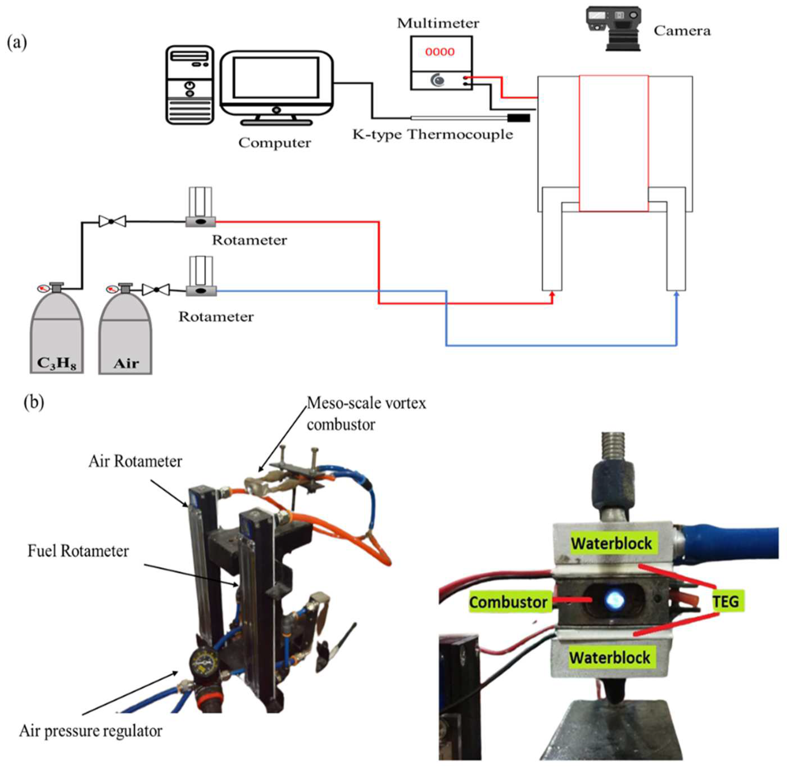
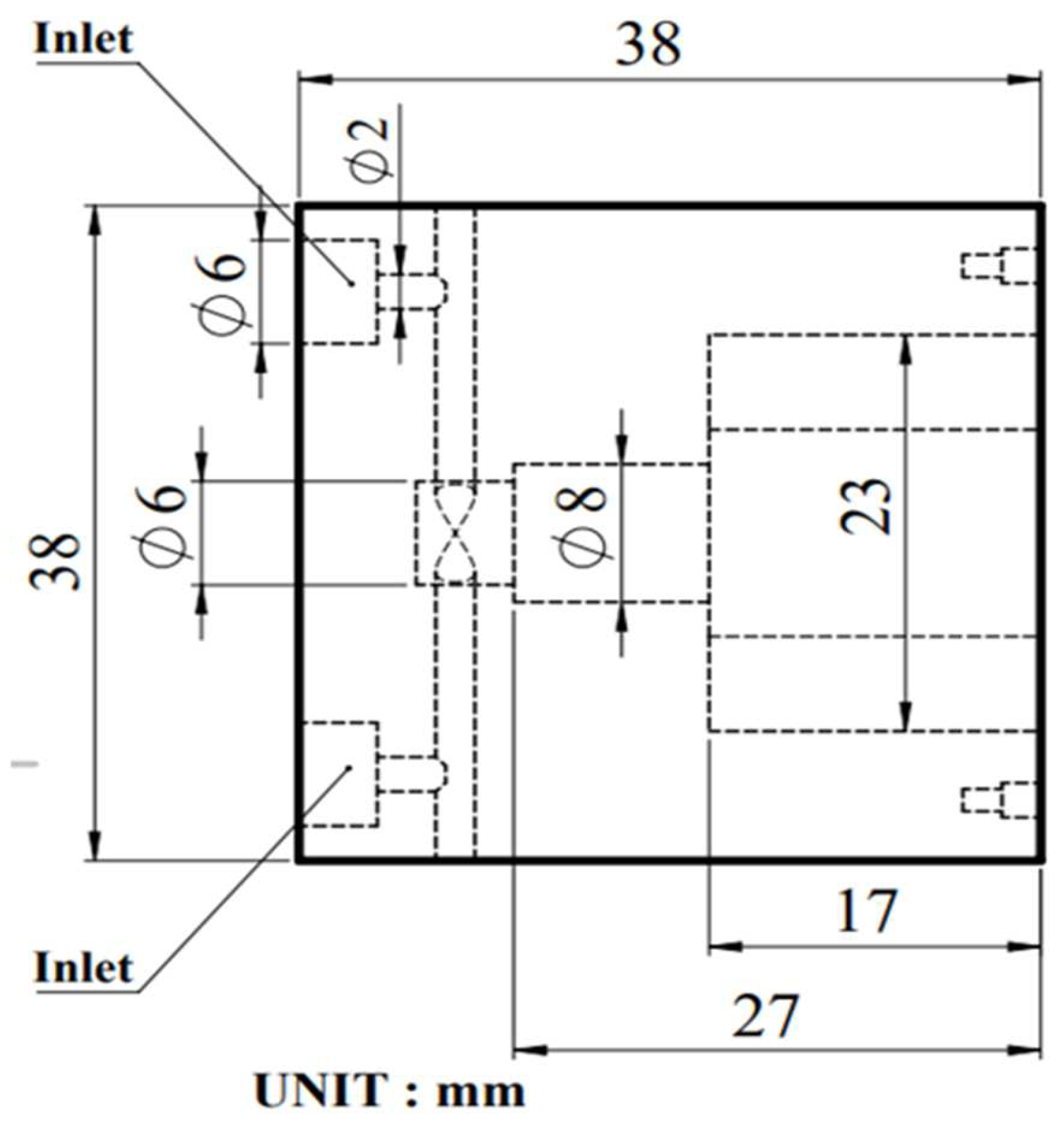
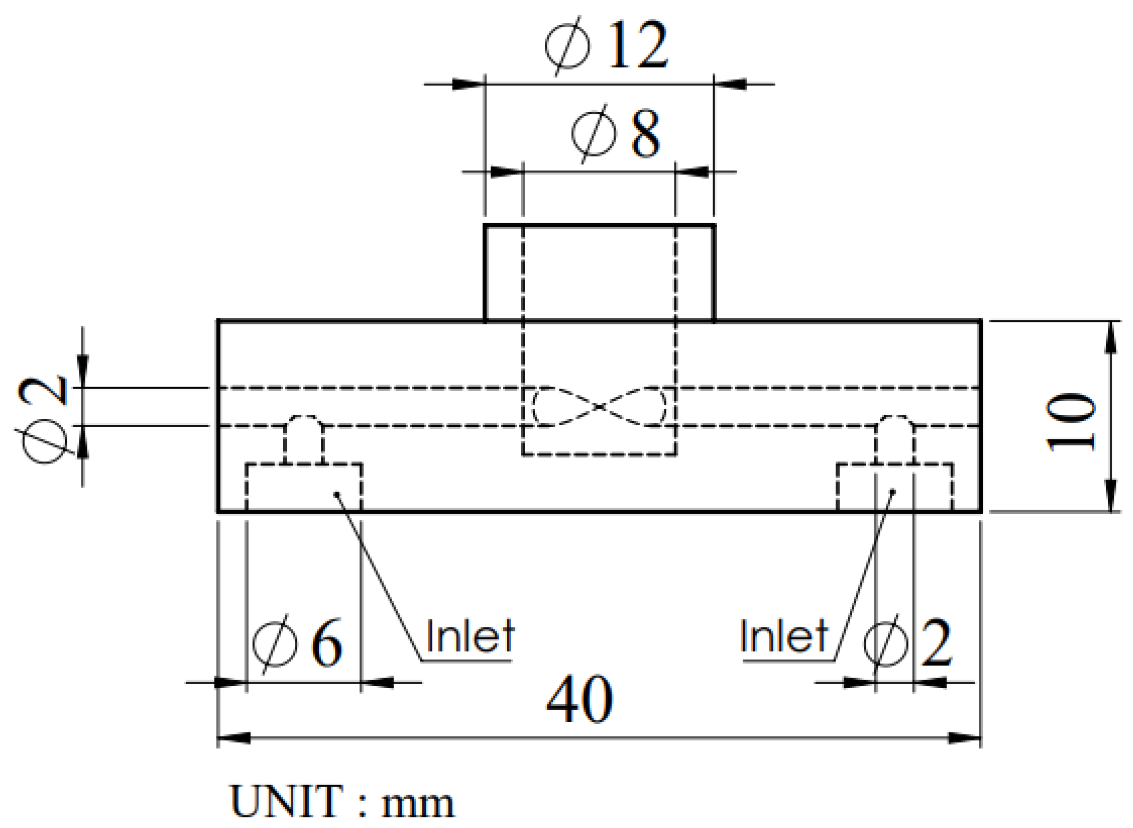
2. Experimental Setup
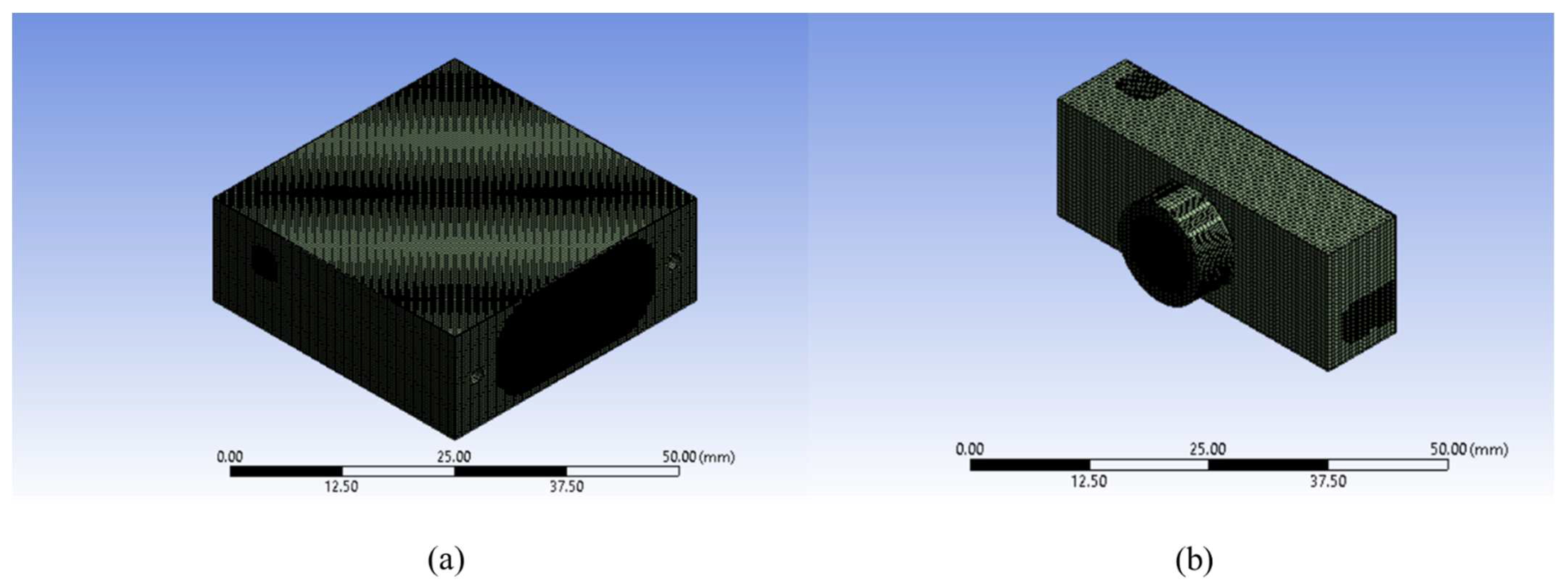
The experimental setup of this study is depicted in Figure 1. Propane gas with a purity of 99% was used as fuel in this experiment, and pressurized air was used as an oxidizer. Fuel and air were separated and mixed inside the vortex chamber. The mass flow rate was controlled using a Rotameter (AALBORG Type PMRI-019406, AALBORG Instrument, New York, NY, USA). The mass flow rate had an interval for propane (20–423 mL/min) and air (24.7–339.6 mL/min). The wall temperature was measured using a K-type thermocouple controlled by an Arduino Mega 2560 (Arduino, Turin, Italy) microcontroller, and a MAX 6675 (Arduino, Italy) sensor was used as the temperature sensor. Flame images were taken using an EOS 70 D (Canon, Tokyo, Japan) to observe flame stability inside the vortex combustion chamber. The electric energy output was monitored using a Tekiro MS-DM1907 digital multimeter (Tekiro Corporation, Tokyo Japan). The fuel inlet velocity used in this experiment was fixed at 0.2 m/s and the air inlet velocity was fixed at 0.6 m/s. In this experiment, a TEG1-12610-4.3 (TECTEG MFR, Aurora, ON, Canada) was used as the thermoelectric generator.
In this study, two different vortex combustors were used. The horizontal vortex combustor is shown in Figure 2. The combustor has dimensions of 38 × 38 × 14 mm, with a 6 mm inlet diameter to stabilize the flame; a backward-facing step was used in the combustion chamber. The vertical vortex combustor is shown in Figure 3. This combustor has dimensions of 40 × 10 × 15 mm, with a 6 mm inlet diameter. In this experiment, stainless steel and aluminum were used as the combustor materials. Electric energy can be obtained using a TEG placed on the surface of the vortex combustor; in this study a water cooling system was used to maximize energy output from the TEG, and the voltage was measured from the TEG. To obtain the electric power, 0.6 ampere power was connected to the TEG voltage power.

Numerical Model

A three-dimensional (3D) numerical simulation was conducted to investigate the development of vertical and horizontal vortex combustion. The numerical simulation was performed using a three-dimensional (3D) steady state by applying computational fluid dynamics (CFD) software, ANSYS release 15. This simulation was running on a computer with an Intel core i5 with 20 GB RAM. The simulation was considered at convergence when the residuals were smaller than 10−5. The COUPLED algorithm was employed to obtain the mass conservation between the velocity and pressure. A volumetric and eddy-dissipation (ED) algorithm was employed as a chemical reaction for turbulence chemistry interaction. The ED reaction model ignores kinetics and uses only reaction flow [27]. With all of these assumptions, the governing equations (mass, momentum, energy, and species transports) were as seen below:
Mass conservation equation:
ρ t + · ρ v = 0
where ρ is the gas density and v is the velocity vector.
Momentum conservation equation:
t ρ v + · ρ v v = p + · τ ¯
where p is the gas static pressure and τ ¯ is the stress tensor.
Energy conservation equation:
t ρ E + · v ρ E + p = · k e f f T i h i J i + τ ¯ · v + S h
where E is the total energy, keff is the effective conductivity, T is the temperature, hi is the enthalpy of species i, J i is the diffusion flux of species i, and Sh is the fluid enthalpy source.
Species transport equation:
t ρ Y i + · ρ v Y i = · J i + R i
where Yi is the mass fraction of species i and Ri is the net rate of production of species i by chemical reaction.
q = h T w , o T + ε σ T w , o 4 T 4
where h0 is the natural convective heat transfer coefficient, which is set as 5 W/(m2·K) as weak natural convection [28]; A is the surface area, Tw is the outer wall temperature, T0 is the ambient temperature, which is set as 300 K, ε is the wall emissivity, and σ is the Stefan–Boltzmann constant, which has a value of 5.67 × 10⁻⁸ W/(m2·K4).
According to Westbrook and Dryer [29], a single one-step propane–air combustion with five species is employed as the combustion chemistry:
C 3 H 8 + 5   O 2   3   CO 2 + 4   H 2 O
The species are C3H8, O2, CO2, N2, and H2O. It should be noted that a detailed kinetic mechanism such as GRI 3.0 must be used if the simulation is used to evaluate the flame or the emission-like (soot formation or NOx) characteristics. The standard K-ε turbulence model was used for the viscous model during the simulation process in this study.
The mesh used in this experiment is shown in Figure 4. In this simulation, the combustor dimension used was the actual size of the experimental combustor (1:1), the cut cell and body sizing were used for the meshing method in this simulation. The vortex combustor simulation consists of two bodies, a solid body and a fluid body; before the simulation was begun, volume extraction was performed to obtain the fluid body. After extracting the volume, the meshing stage was then entered. The meshing stage began with identifying the combustor parts, namely: inlet 1, inlet 2, outlet, wall body, fluid, and ignition fluid. Inlet 1 and inlet 2 were used as fuel and air inlets and outlets as exhaust combustion outlets; the body wall was the combustor wall, and fluid was the fluid that fills the combustor cavity. Figure 5. shows the computational domain of this simulation; purple indicates the solid body and blue indicates the fluid body. The detail of the boundary condition is shown in Table 1.
For simulation accuracy, the grid independence test was performed before the simulation. In the vertical vortex combustor, meshes with a different size were tested: 0.15 mm, 0.20 mm, and 0.25 mm. The grid independence result showed that 0.15 mm had a smooth graph, but this mesh required the longest time to obtain a converged result. Therefore, we chose 0.20 mm as the mesh size for the simulation. Figure 6. shows the grid independence test result for flame temperature for radial direction.

3. Results and Discussion

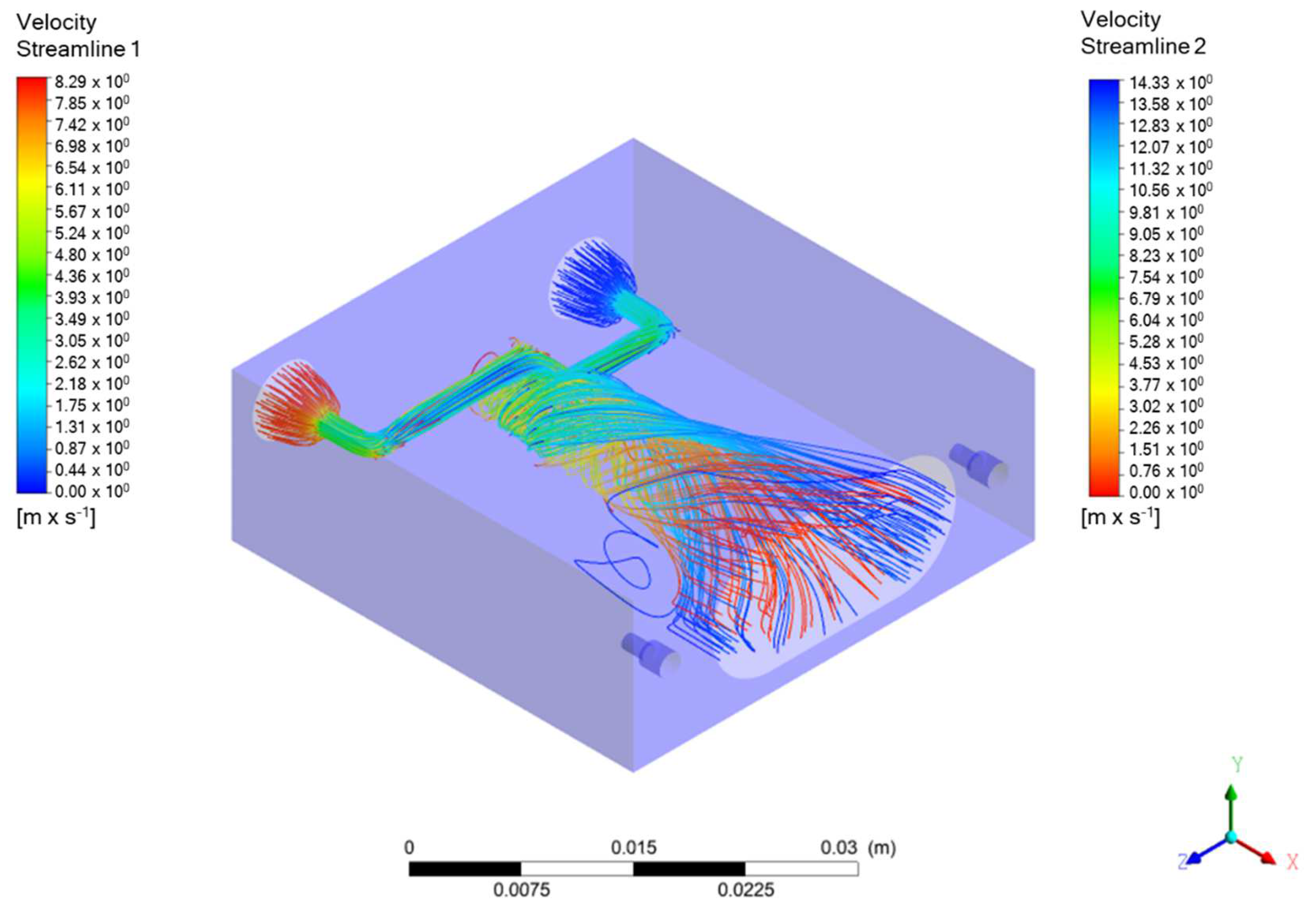
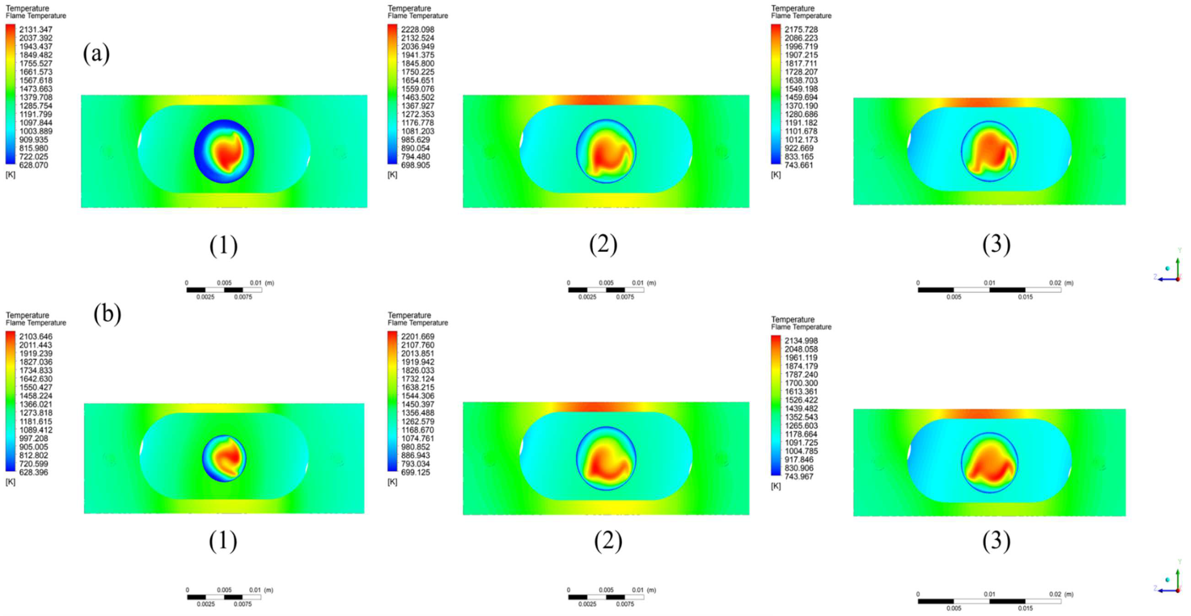
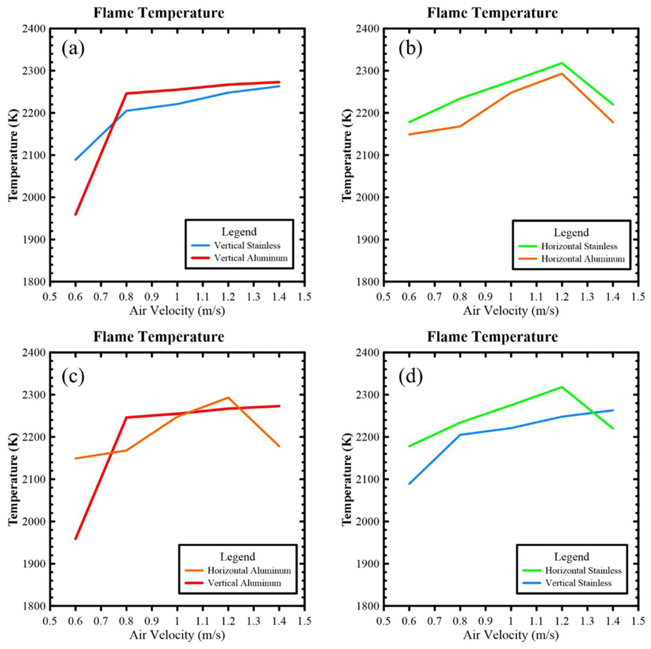
3.1. Numerical Simulation Results

The velocity streamline is shown in Figure 7. On the velocity streamline, the velocity at the back of the combustor is faster than the velocity when entering the combustor; this is due to the tangential velocity effect, which makes the velocity higher. This also allows the flame to be stabilized in the vortex area because the velocity of the fuel and air mixture is faster than the velocity of the flame. Velocity streamline 1 shows the velocity streamline of the fuel, and velocity streamline 2 shows the air. Figure 8. shows the cross-sectional temperature profile along the Z-axis; according to this cross-sectional profile the flame temperature can be found at 14. The detailed temperature results are shown in Figure 9.
The velocity streamline of the horizontal vortex combustor is shown in Figure 10. On the velocity streamline, the velocity at the back of the combustor is faster than the velocity when entering the combustor; this is due to the tangential velocity effect, which makes the velocity higher. This is also allowing the flame to be stabilized in the vortex area because the velocity of the fuel and air mixture is faster than the velocity of the flame. Streamline 1 shows the velocity of fuel and streamline 2 shows the velocity of the air. Figure 11. shows the cross-sectional temperature profile along the X-axis, according to this cross-sectional profile the flame temperature can be found at 14. Detailed temperature results are shown in Figure 12.
According to the numerical simulation results, the flame temperature for the stainless horizontal vortex combustor had the highest temperature. Figure 13. shows the flame temperature results for the vertical and horizontal vortexes and aluminum and stainless-steel materials. Figure 14. shows the wall temperature for vertical and horizontal vortex combustors. According to the simulation results, the aluminum and stainless-steel combustors had similar wall temperatures.

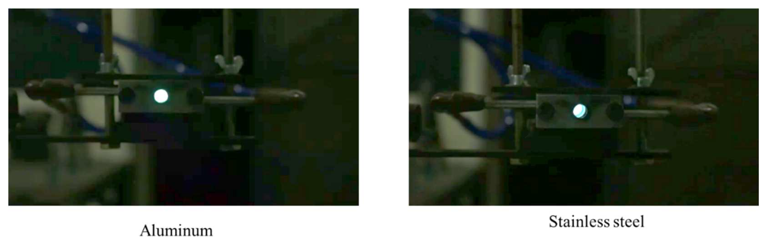
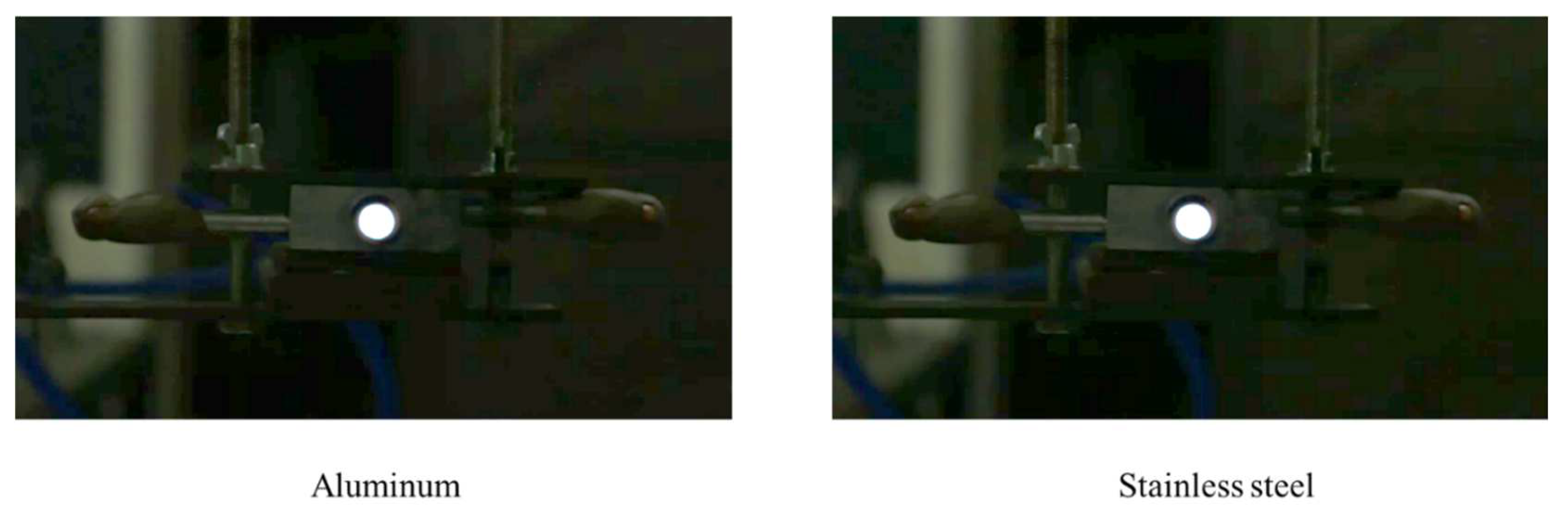
3.2. Flame Appearance

In this study, several velocities were tested to obtain a stable flame; in the end, velocities of 0.2 and 0.6 m/s showed the most stable flame. Due to the greater length dimension of the horizontal combustor, it is possible that the velocity can be increased to be faster than with the vertical combustor. the flame image of the horizontal combustor was shown in Figure 15.
The photograph in Figure 16. shows a stable flame condition on the vertical vortex combustor. To facilitate shooting, the combustor was rotated 90 degrees, so that the flame could be observed and compared with the horizontal combustor. The fuel inlet velocity was fixed at 0.2 m/s, and the air inlet velocity was fixed at 0.6 m/s. A blue flame front was observed in both the aluminum and stainless-steel horizontal vortex combustors.

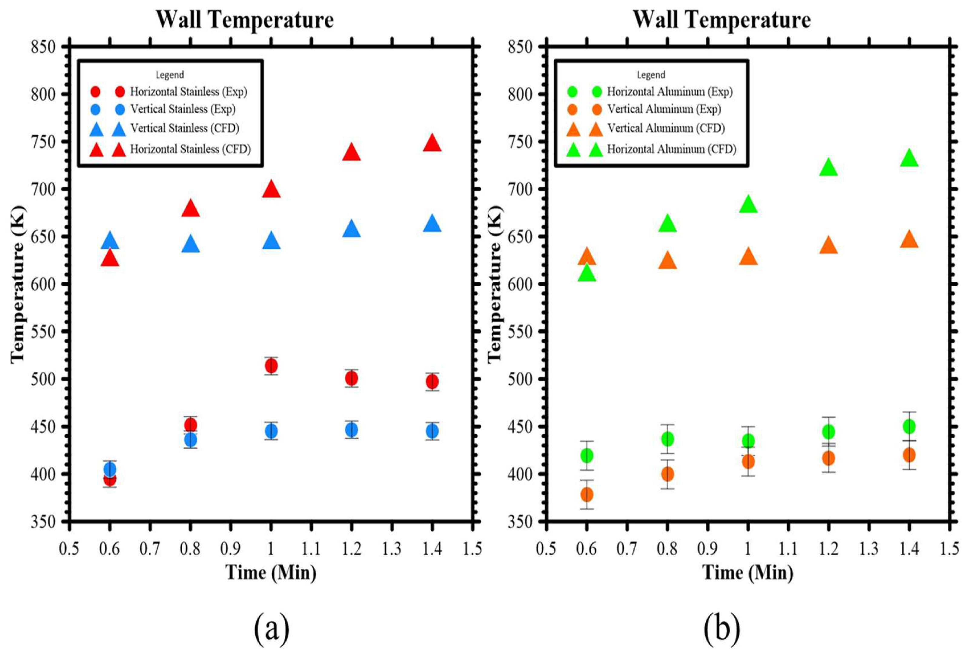
3.3. Temperature Measurement

Similar to stainless steel wire mesh, a vortex combustor has the function of stabilizing the flame; the backward-facing step design in the vortex combustor is to hold the position of the flame and prevent flashback. Due to the high temperatures generated by the meso-scale combustor, heat energy from the wall temperature can be transferred into electric energy using a thermoelectric generator (TEG) [20]. In this experiment, the wall temperature was measured, while at the same time the voltage output from the TEG was also measured. Figure 17. shows the comparation of wall temperatures for the vortex combustors in the experimental and computational studies. The wall temperature measurement indicated that the stainless steel horizontal combustor had a higher temperature than the aluminum combustor. Nevertheless, in terms of material variation the stainless steel combustor had a higher temperature than the aluminum combustor.
Figure 18 shows the voltage measurement for the vortex combustor. The voltage measurement indicated that the horizontal combustor has higher energy output than the aluminum combustor. Nevertheless, for the material variation stainless steel combustor has a higher energy output than an aluminum combustor. this experiment showed that the heat transfer from the burning gas towards the burner wall was significantly increased by the vortex flow, which contributed to the conversion of the combustion chamber. The voltage generated from each combustor will follow the temperature that occurs in the combustor, the seebeck effect on the TEG is used to measure the voltage on the combustor where the electrical energy produced will be proportional to the temperature gradient. The temperature difference in the hot and cold parts of TEG increases, the electricity output will also increase too.
According to temperature and voltage measurements, the stainless steel horizontal vortex combustor had the highest measurement point, which would maximize the energy output of the stainless-steel horizontal vortex combustor. To maximize the electric energy output from the meso-scale vortex combustor, we also used two TEGs to measure the voltage energy output of the stainless-steel horizontal combustor. Figure 19. shows the voltage output measurement for two TEGs with series and parallel circuits. According to the results, the double TEGs with a water-cooled system had the highest voltage output.

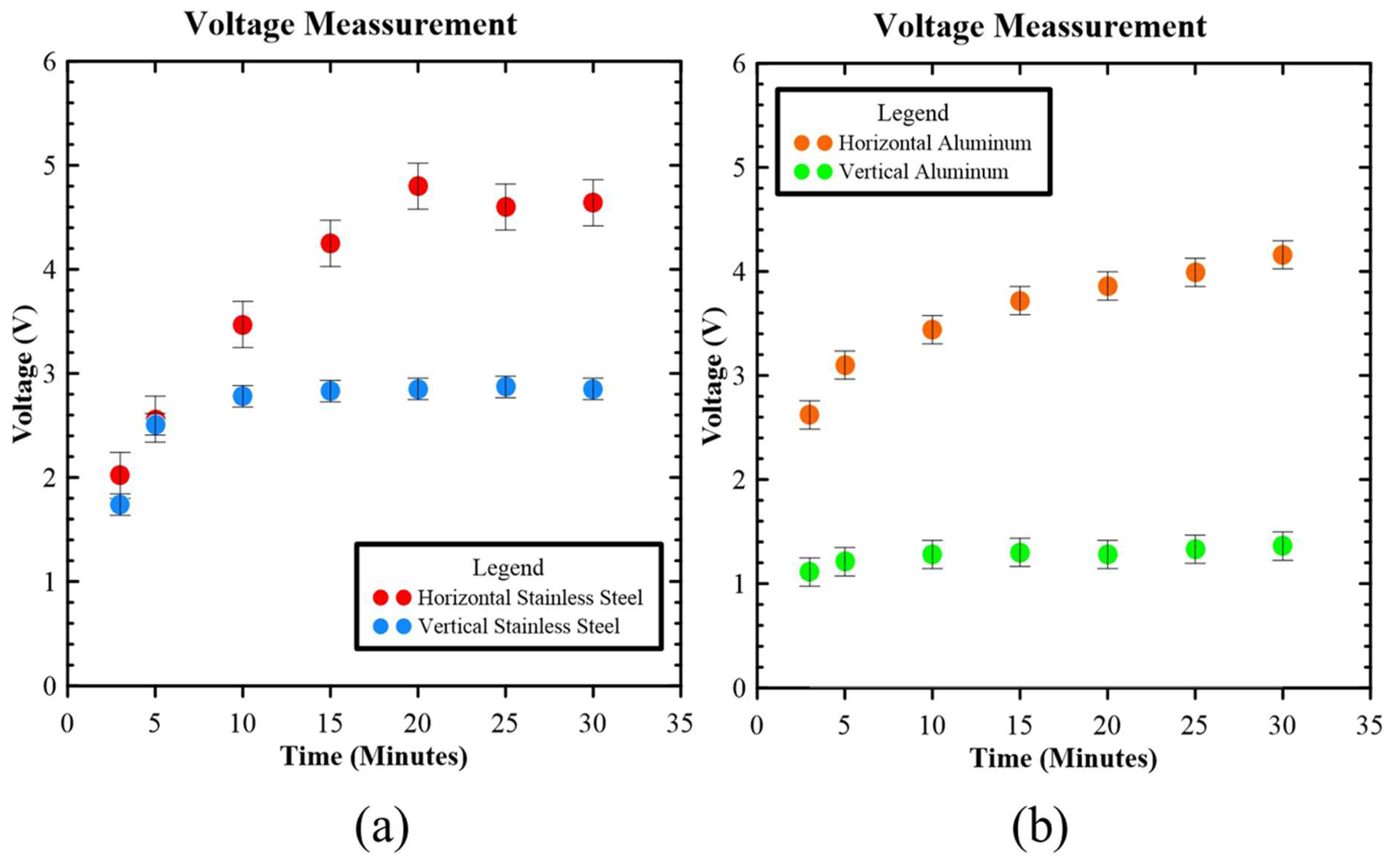
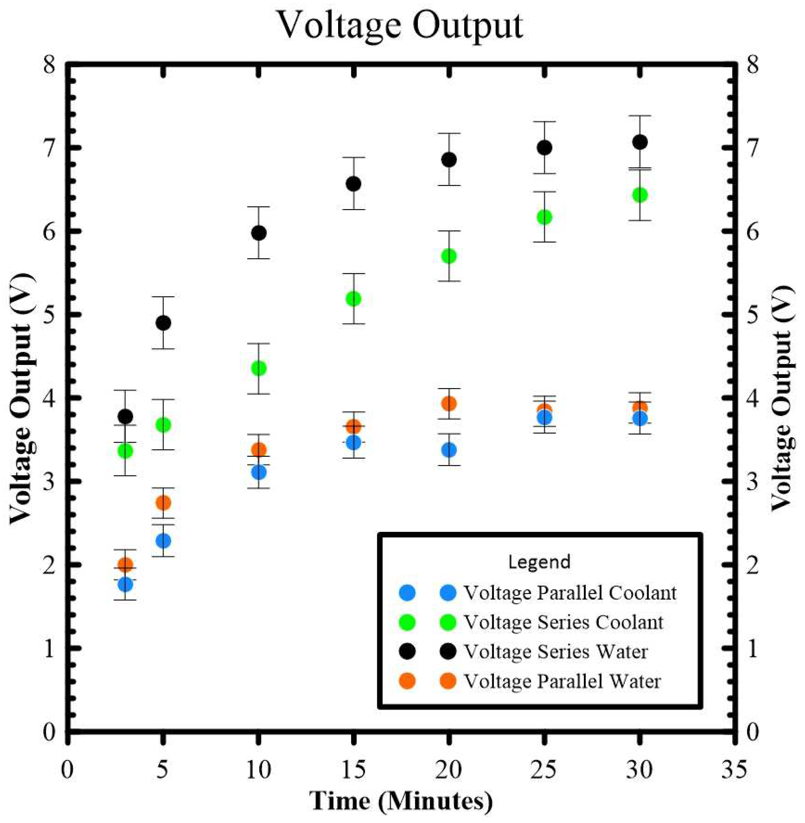
3.4. Power Output Measurement

The purpose of developing a micro power generator based on a thermoelectric generator (TEG) was to obtain power output that can be used as a portable electric generator. In our study, to analyze the power output we used 0.6 A as a current. Table 2. shows the power output calculation for each case.
P = V × I
where:
P: Power (Watt)
V: Voltage (V)
I: Electric Current (A)

4. Conclusions

This study focused on the development of a meso-scale vortex combustor to obtain the electric energy for a micro power generator. In this study, different materials and different vortex designs were analyzed. A numerical and experimental method was used to analyze the development of the vortex combustor. According to the numerical simulation and experimental study, the main conclusions of this study are:
  • Based on the simulation results for the vertical and horizontal vortex combustors, the flame temperature of the horizontal combustor made from stainless steel had the highest flame temperature.
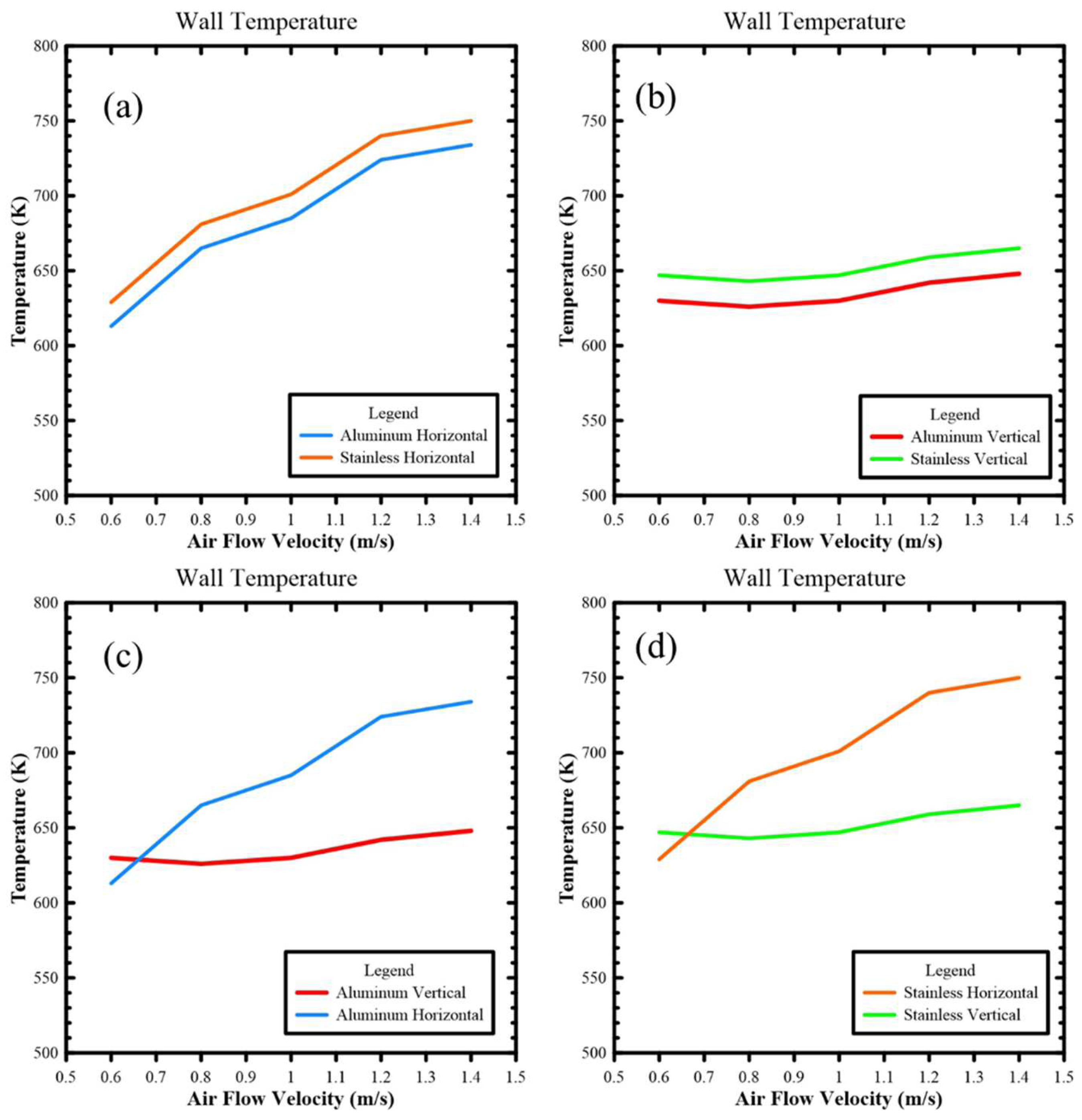
  • Based on the simulation results for the vertical and horizontal vortex combustors, the wall temperature of the horizontal combustor made from stainless material had the highest wall temperature; the thermal conductivity of aluminum was better than stainless steel.
  • Based on the experimental results for the vertical and horizontal vortex combustors, the horizontal vortex combustor had a higher temperature than the vertical vortex combustor. In regard to the material, the horizontal combustor made with stainless steel had a higher wall temperature.
  • To analyze the electric energy generated from the meso-scale vortex combustor, the stainless material horizontal combustor was selected. According to the results, two TEGs with a series circuit using a water-cooled system had higher energy output than the other options; this combustor can generate at least 3.6 watts.

Author Contributions

H.S., conceptualization, funding acquisition, supervision, project administration, writing—review and editing; L.F., funding acquisition, supervision; A.P., data curation, formal analysis, methodology, writing—original draft; F.A.M., numerical analysis, supervision, writing—review and editing; W.-C.W., supervision, writing—review and editing. All authors have read and agreed to the published version of the manuscript.

Funding

This research was funded by the LPPM Universitas Sebelas Maret through the International Collaboration Grant 2021, Grant Number 260/UN27.22/HK.07.00/2021.

Data Availability Statement

Not applicable.

Conflicts of Interest

The authors declare no conflict of interest.

References

  1. Walther, D.C.; Ahn, J. Advances and challenges in the development of power-generation systems at small scales. Prog. Energy Combust. Sci. 2011, 37, 583–610. [Google Scholar] [CrossRef]
  2. Ju, Y.; Maruta, K. Microscale combustion: Technology development and fundamental research. Prog. Energy Combust. Sci. 2011, 37, 669–715. [Google Scholar] [CrossRef]
  3. Chou, S.; Yang, W.; Li, J.; Li, Z. Porous media combustion for micro thermophotovoltaic system applications. Appl. Energy 2010, 87, 2862–2867. [Google Scholar] [CrossRef]
  4. Yang, W.M.; Chou, S.K.; Shu, C.; Li, Z.W.; Xue, H. Development of microthermophotovoltaic system. Appl. Phys. Lett. 2002, 81, 5255–5257. [Google Scholar] [CrossRef]
  5. Fernandez-Pello, A.C. Micropower generation using combustion: Issues and approaches. Proc. Combust. Inst. 2002, 29, 883–899. [Google Scholar] [CrossRef] [Green Version]
  6. Jiaqiang, E.; Luo, B.; Han, D.; Chen, J.; Liao, G.; Zhang, F.; Ding, J. A comprehensive review on performance improvement of micro energy mechanical system: Heat transfer, micro combustion and energy conversion. Energy 2022, 239, 122509. [Google Scholar] [CrossRef]
  7. Lee, S.; Um, D.; Kwon, O. Performance of a micro-thermophotovoltaic power system using an ammonia-hydrogen blend-fueled micro-emitter. Int. J. Hydrogen Energy 2013, 38, 9330–9342. [Google Scholar] [CrossRef]
  8. Li, Y.-H.; Hong, J.R. Power generation performance of hydrogen-fueled micro thermophotovoltaic reactor. Int. J. Hydrogen Energy 2018, 43, 1459–1469. [Google Scholar] [CrossRef]
  9. Wang, W.; Zhao, Z.; Kuang, N.; Chen, H.; Liu, J.; Zuo, Z. Experimental study and optimization of a combustion-based micro thermoelectric generator. Appl. Therm. Eng. 2020, 181, 115431. [Google Scholar] [CrossRef]
  10. Kuo, C.; Ronney, P. Numerical modeling of non-adiabatic heat-recirculating combustors. Proc. Combust. Inst. 2007, 31, 3277–3284. [Google Scholar] [CrossRef]
  11. Tang, A.; Cai, T.; Huang, Q.; Deng, J.; Pan, J. Numerical study on energy conversion performance of micro-thermophotovoltaic system adopting a heat recirculation micro-combustor. Fuel Process. Technol. 2018, 180, 23–31. [Google Scholar] [CrossRef]
  12. Khandelwal, B.; Deshpande, A.A.; Kumar, S. Experimental studies on flame stabilization in a three step rearward facing configuration based micro channel combustor. Appl. Therm. Eng. 2013, 58, 363–368. [Google Scholar] [CrossRef]
  13. Mikami, M.; Maeda, Y.; Matsui, K.; Seo, T.; Yuliati, L. Combustion of gaseous and liquid fuels in meso-scale tubes with wire mesh. Proc. Combust. Inst. 2013, 34, 3387–3394. [Google Scholar] [CrossRef]
  14. Saputro, H.; Ariyanto, E.D.; Wijayanto, D.S.; Muslim, R.; Fitriana, L.; A Munir, F. An experimental study into the effect of fuel on step micro-combustor to the flame stability characterization. J. Phys. Conf. Ser. 2021, 1808, 012020. [Google Scholar] [CrossRef]
  15. Saputro, H.; Purwanto, A.; Fitriana, L.; Wijayanto, D.S.; Sutrisno, V.L.P.; Ariyanto, E.D.; Bima, M.; Pratama, Y.; Juwantono, H.; Firdani, T.; et al. Analysis of flame stabilization limit in a cylindrical of step micro-combustor with different material through the numerical simulation. MATEC Web Conf. 2018, 197, 08003. [Google Scholar] [CrossRef]
  16. Saputro, H.; Bima, M.; Fitriana, L.; Wijayanto, D.S.; Bugis, H.; Munir, F.A. Optimization of thermal energy of cylindrical micro-combustor by using the different materials. In Proceedings of the 7th Mechanical Engineering Research Day (MERD'20)—Kampus Teknologi UTeM, Virtual, 16 December 2020. [Google Scholar]
  17. Abdul Munir, F.; Muazzam, M.I.; Gader, A.; Mikami, M.; Saputro, H.; Fitriana, L. Effects of Wall Thickness on Flame Stabilization Limits for Combustors with Wire Mesh. J. Adv. Res. Fluid Mech. Therm. Sci. 2020, 49, 11–17. [Google Scholar]
  18. Munir, F.A.; Mikami, M. A numerical study of propane-air combustion in meso-scale tube combustors with concentric rings. J. Therm. Sci. Technol. 2015, 10, JTST0008. [Google Scholar] [CrossRef] [Green Version]
  19. Tan, N.D.M.R.; Munir, F.A.; Tahir, M.M.; Saputro, H.; Mikami, M. Preliminary Investigation of Using DBD Plasma for Application in Micro Combustors. J. Adv. Res. Fluid Mech. Therm. Sci. 2021, 82, 105–112. [Google Scholar] [CrossRef]
  20. Shimokuri, D. Autonomous Power System Using Small Scale Vortex Combustor. J. Phys. Conf. Ser. 2018, 1052, 012003. [Google Scholar] [CrossRef]
  21. Shimokuri, D.; Hara, T.; Ishizuka, S. Development of a portable power system with meso-scale vortex combustor and thermo-electric device. J. Phys. Conf. Ser. 2014, 557, 012117. [Google Scholar] [CrossRef]
  22. Shimokuri, D.; Taomoto, Y.; Matsumoto, R. Development of a powerful miniature power system with a meso-scale vortex combustor. Proc. Combust. Inst. 2017, 36, 4253–4260. [Google Scholar] [CrossRef]
  23. Wu, M.-H.; Wang, Y.; Yang, V.; Yetter, R.A. Combustion in meso-scale vortex chambers. Proc. Combust. Inst. 2007, 31, 3235–3242. [Google Scholar] [CrossRef]
  24. Aravind, B.; Raghuram, G.K.; Kishore, V.R.; Kumar, S. Compact design of planar stepped micro combustor for portable thermoelectric power generation. Energy Convers. Manag. 2018, 156, 224–234. [Google Scholar] [CrossRef]
  25. Saputro, H.; Juwantono, H.; Bugis, H.; Wijayanto, D.S.; Fitriana, L.; Perdana, V.L.; Purwanto, A.; Arianto, E.D.; Bima, M.; Pratama, Y.; et al. Numerical simulation of flame stabilization in meso-scale vortex combustion. MATEC Web Conf. 2018, 197, 08005. [Google Scholar] [CrossRef]
  26. Ben Khedher, N.; Selimefendigil, F.; Kolsi, L.; Aich, W.; Ben Said, L.; Boukholda, I. Performance Optimization of a Thermoelectric Device by Using a Shear Thinning Nanofluid and Rotating Cylinder in a Cavity with Ventilation Ports. Mathematics 2022, 10, 1075. [Google Scholar] [CrossRef]
  27. ANSYS Inc. ANSYS Fluent Theory Guide Release 15; ANSYS Inc.: Canonsburg, PA, USA, 2013. [Google Scholar]
  28. Li, J.; Chou, S.; Yang, W.; Li, Z. A numerical study on premixed micro-combustion of CH4–air mixture: Effects of combustor size, geometry and boundary conditions on flame temperature. Chem. Eng. J. 2009, 150, 213–222. [Google Scholar] [CrossRef]
  29. Westbrook, C.K.; Dryer, F.L. Simplified Reaction Mechanisms for the Oxidation of Hydrocarbon Fuels in Flames. Combust. Sci. Technol. 1981, 27, 31–43. [Google Scholar] [CrossRef]
Figure 1. (a) Experimental apparatus (b) actual photograph of experimental setup and combustor layout.
Fluids 07 00386 g001
Figure 2. Horizontal vortex combustor dimensions.
Fluids 07 00386 g002
Figure 3. Vertical vortex combustor dimensions.
Fluids 07 00386 g003
Figure 4. The numerical simulation mesh (a) horizontal vortex combustor and (b) vertical vortex combustor.
Fluids 07 00386 g004
Figure 5. Computational domain and boundary condition of the simulation (a) horizontal vortex combustor and (b) vertical vortex combustor.
Fluids 07 00386 g005
Figure 6. Grid independence test.
Fluids 07 00386 g006
Figure 7. Vertical vortex combustor velocity streamline.
Fluids 07 00386 g007
Figure 8. Temperature profile on the cross-section of z = 5, 8, 11, 14, and 17 in the vertical vortex combustor.
Fluids 07 00386 g008
Figure 9. The vertical vortex combustor flame temperatures for (a) aluminum and (b) stainless steel material with fuel velocity 0.2; (1) air velocity 0.6, (2) air velocity 1.0, and (3) air velocity 1.4 m/s.
Fluids 07 00386 g009
Figure 10. Horizontal vortex combustor velocity streamline.
Fluids 07 00386 g010
Figure 11. Temperature profile on cross section of x = 2, 8, 14, 20, and 26 in the vertical vortex combustor.
Fluids 07 00386 g011
Figure 12. The vertical horizontal combustor flame temperatures for (a) aluminum and (b) stainless steel material with fuel velocity 0.2; (1) air velocity 0.6, (2) air velocity 1.0, and (3) air velocity 1.4 m/s.
Fluids 07 00386 g012
Figure 13. Flame temperatures from numerical simulations for (a) vertical vortex combustor, (b) horizontal vortex combustor, (c) vortex combustor with aluminum material, and (d) vortex combustor with stainless material.
Fluids 07 00386 g013
Figure 14. Wall temperatures from numerical simulation for (a) horizontal combustor, (b) vertical combustor, (c) aluminum material, and (d) stainless material.
Fluids 07 00386 g014
Figure 15. Stable flame appearance in horizontal vortex combustors.
Fluids 07 00386 g015
Figure 16. Stable flame appearance in vertical vortex combustors.
Fluids 07 00386 g016
Figure 17. Wall temperature measurements for (a) stainless steel and (b) aluminum combustors.
Fluids 07 00386 g017
Figure 18. Voltage measurement for (a) stainless steel and (b) aluminum combustors.
Fluids 07 00386 g018
Figure 19. Voltage measurement for a two-TEG system.
Fluids 07 00386 g019
Table 1. Boundary Condition Details.
BoundaryVariableValue
InletOxidizer Velocity (m/s)0.6–1.4
Fuel Velocity (m/s)0.2
Temperature (K)300
Species Mole Fraction1 for C3H8
0.21 for O2
Gauge Pressure (Pa)0
Hydraulic Diameter (mm)6
OutletSpecies Mole Fraction0.21 for O2
Temperature (K)300
Gauge Pressure (Pa)0
Hydraulic Diameter (mm)8
Outer WallThermal ConditionMixed
Heat Transfer Coefficient (W/(m2·K))5
MaterialStainless Steel
Aluminum
Table 2. Electric power calculation for each case.
NameVoltage (V)Ampere (A)Power (Watt)
Single Water3.7910.62.275
Single Coolant3.5800.62.148
Parallel Water3.3460.62.007
Parallel Coolant3.0790.61.847
Series Water6.0230.63.614
Series Coolant4.9840.62.991
Publisher’s Note: MDPI stays neutral with regard to jurisdictional claims in published maps and institutional affiliations.

