Article

A Molecular Dynamics Study on the Tribological Performance of Imidazolium−Based Ionic Liquids Mixed with Oil in Comparison to Pure Liquids

1
School of Polymer Science and Polymer Engineering, The University of Akron, Akron, OH 44325, USA
2
Department of Chemical, Biomolecular, and Corrosion Engineering, The University of Akron, Akron, OH 44325, USA
*
Author to whom correspondence should be addressed.
Fluids 2022, 7(12), 384; https://doi.org/10.3390/fluids7120384
Submission received: 1 November 2022 / Revised: 6 December 2022 / Accepted: 8 December 2022 / Published: 14 December 2022

Abstract

:
The purpose of this work is to propose an advanced lubricant model of ILs used as additives to conventional oil. All-atoms molecular dynamics simulations are used to investigate the structure and tribology of oxidatively stable pure imidazolium-based ionic liquids (ILs), branched alkane low friction oil, and a mixture of ILs and oil confined between iron surfaces. Equilibrium and shear simulations are performed at a temperature of 450 K and undergo different applied loads and shear velocities to mimic engine operations. Density profiles reveal the formation of layered structures at the interface. The intensity and number of the density peaks vary according to the composition of the system and the applied pressure. Velocity profiles reveal the presence of no-slip conditions in the pure ILs system and very high slip for the oil. The presence of a stable IL layer at the surface of the mixed lubricant fully reduces the slip of oil. Overall, the mixture displays lower friction in comparison to pure ILs. The formed corrosion protective anion layer on the metal surface makes the mixture a potential candidate for a new generation of high-performance lubricants.

1. Introduction

Lubricants are materials that extend the service life of machinery by reducing the friction of rolling and sliding parts [1]. The ultimate objective of the science of tribology is to design high-performance, multi-functional, environmentally friendly, low-cost, and easy-to-process lubricants [2]. Conventional lubricants such as natural oils already possess such features as low friction coefficients (<0.15) and non-toxicity that is typically not accessible by other one-component lubricating fluids [3,4]. On the contrary, they lack thermal and oxidation stability in addition to solidification and loss of oil under high pressures [5]. It is a significant disadvantage as the oils are subject to extreme normal and shear loads in industrial settings (i.e., metal forming and ball-bearing) [6,7,8,9,10]. Hydrocarbons or n-alkanes under confined conditions experience an interfacial phenomenon where a solid-like behavior of the confined liquid takes place [11,12]. The consequences of this behavior are the ordering of molecules at the solid surface, density oscillations within the oil film, the increase in shear viscosity, and velocity slip [13]. It is especially critical when the gap between the confining slabs approaches nanometer thickness under high pressures and shear rates [14,15,16,17,18]. The surface roughness [12,13] and the interfacial layer adsorption [19,20] are shown to affect the properties of the lubricant as well.
Ionic liquids (ILs) are molten salts known for their low vapor pressure and promising thermo-rheological behavior. The useful properties of ILs have attracted a substantial amount of attention to be used in various applications. Specifically, ILs have been proposed to become potential candidates for energy conservation solutions, designer solvents, and a new generation of lubricants [21]. The latter is of interest for this study of enhancing the tribological performance of conventional oils. The tribological research on ILs often emphasizes the replacement of conventional lubricants. For example, ILs improved friction reduction and antiwear capabilities in comparison to frequently used polyalphaolefins, phosphazene, polyol esters, and perfluoropolyether lubricants [22]. Moreover, ILs outperformed many gears, engines, and commercial hydraulic oils [22]. ILs demonstrate no significant difference in performance under no pressure and high pressure conditions in steel-steel contacts, showing the ability to withstand extreme loads [23]. It is found that the superior tribological performance lies in the deposition of ions on the solid sliding parts. This interfacial confined film does not allow direct contact with metal surfaces and lowers their friction.
The performance of ILs as lubricants relies on the stable film formation mechanism between the interacting surfaces. It has been observed that cations and anions under confinement orient in particular patterns [24,25]. Similar to ordered layers in graphite, ILs nanostructures are characterized by a low interlayer strength, making them ideal lubricant candidates [26]. In addition, Xiao et al. [27] carried out experiments at very high pressures (up to 3 GPa), comparing the film-forming ability of imidazolium-based ILs against that of conventional silicon oil. It was shown that when the viscosity was equivalent in both systems, ILs formed a thicker film than oil and performed better overall under high loads. Recent molecular dynamics simulations studies showed that ILs tend to bind strongly on the iron surface and can be used as corrosion inhibitors or metal decontamination substrates [28]. The intensity of these effects can be tuned by controlling the length of the cation alkyl chain [28]. Likewise, ILs films on diamond-like carbon surfaces can reduce friction through the restriction of C–C bond formation between the sliding interfaces [29].
Conventional oils are limited in high-temperature environments due to their tendency to decompose. The thermal stability of ILs thus offers another advantage to available lubricants as they can withstand temperatures up to 670 K without undergoing degradation [30]. In fact, some imidazolium ILs display heat resistance to temperatures up to 750 K while maintaining their characteristic of low-temperature fluidity (glass transition temperature, of ILs can vary from 157 K to 433 K) [31,32]. This allows ILs to operate in a wide range of temperatures.
Properties such as low volatility and non-flammability are crucial for the design of lubricants, as they can minimize evaporation and fire hazards while transporting and handling the material. In addition, the thermo-oxidative and chemical stability of ILs prevents corrosive processes from taking place, thus protecting and extending the lifetime of machinery [33,34]. The low toxicity and high biodegradability of many ILs are also advantageous from an industrial perspective, as they prevent hazardous risks for both workers and the environment [35]. Finally, as ILs are composed of at least two ions, a vast database of ILs (>106) can be explored to design lubricants that can be tuned and adapted according to different sliding contacts or specific requirements of the machinery [36,37]. In many research papers, neat ILs are explored to become a new generation of lubricants [26,36,38,39,40,41]. Such studies allow applying all the exceptional physicochemical properties of ionic liquids to lubrication. However, IL chemistry tends to be complex and expensive, leading to financial challenges in industrial settings. Therefore, there are studies done to discover the possibility of using ILs as additives to conventional lubricants [26,36,38,39,40,42,43,44,45,46,47,48,49].
For example, 1% of [N12,H,H,H][Cl] was added to oil to lubricate steel-aluminum contact surfaces. [P6,6,6,14][DEHP] ILs additives achieved steady lubrication and reduction of friction at a high temperature of 373 K. At the same time, a common antiwear agent zinc dialkyl dithiophosphate (ZDDP) only showed good performance under ambient conditions [50]. In a steel–steel contact experiment, a substantial wear decrease was seen after adding 1–5 wt% of bisimidazolium IL to poly(ethylene glycol) (PEG) [51]. Overall, it was proved that a small amount of IL in a base oil can greatly enhance the tribological performance of the mixture in comparison to neat oil [43,52]. Moreover, experimental results concluded that in many cases such mixed lubricants can outperform standalone ILs in wear reduction.
In this work, we use atomistically detailed molecular dynamics simulations to predict the structural and tribological properties of imidazolium-based ILs with the linear and branched alkyl chain of cation (1-heptyl-3-methylimidazolium and 1-(5-methylhexyl)-3-methylimidazolium) and bis[(trifluoroethane)sulfonyl]imide anion, oil (9-octylheptadecane), and IL-based lubricants under metal confinement. The bis[(trifluoroethane)sulfonyl]imide anion displays superior oxidative stability to other anions [53]. Thus, it was selected for our study. Two types of cations with long alkyl chains (branched and linear) are chosen for this study because the length of the alkyl chains of cations is a controlling factor for tribological performance. It has been found that long side chains show improved friction and wear performance [54,55,56,57]. The n-alkanes with long molecular chain lengths demonstrate the same advances [16]. In addition, the branched n-alkanes yield an increase in shear stresses and stay in the liquid phase under higher applied pressures than linear molecules in confinement [19]. That is why 9-octylheptadecane is given a preference to represent a low friction model oil in this research. Lastly, the most common rolling and sliding materials in industry are steel and iron, so we chose iron to confine the liquids [58,59].
Our previous study showed that ions create layered structures near the solid-liquid interface, and these layers are strongly adsorbed to the iron surface [60]. Here, we characterize the structure from density profile data after equilibrium simulations to get an insight into molecular ordering under extreme confinement. We then analyze the flow behavior and the stress response of the liquids after shear flow simulations with various flow strengths. To understand the efficiency of the designed lubricant, we calculate and compare the friction coefficient for all the studied systems. Our goal is to keep the low friction coefficient that hydrocarbon lubricants offer while maintaining the stability of the liquid layer on the surface to prevent the metal surface from degradation. Thus, ILs will have enhanced tribological properties for lubrication when used as additives to conventional oils.
This paper is constructed as follows: Section 2 is dedicated to the discussion of detailed simulation methodology. Section 3 uncovers the interfacial and tribological phenomena of the resulting lubricant compared to other studied liquids under different confinement and shear conditions. In Section 4, concluding remarks on the subject and future efforts are presented.

2. Computational Details

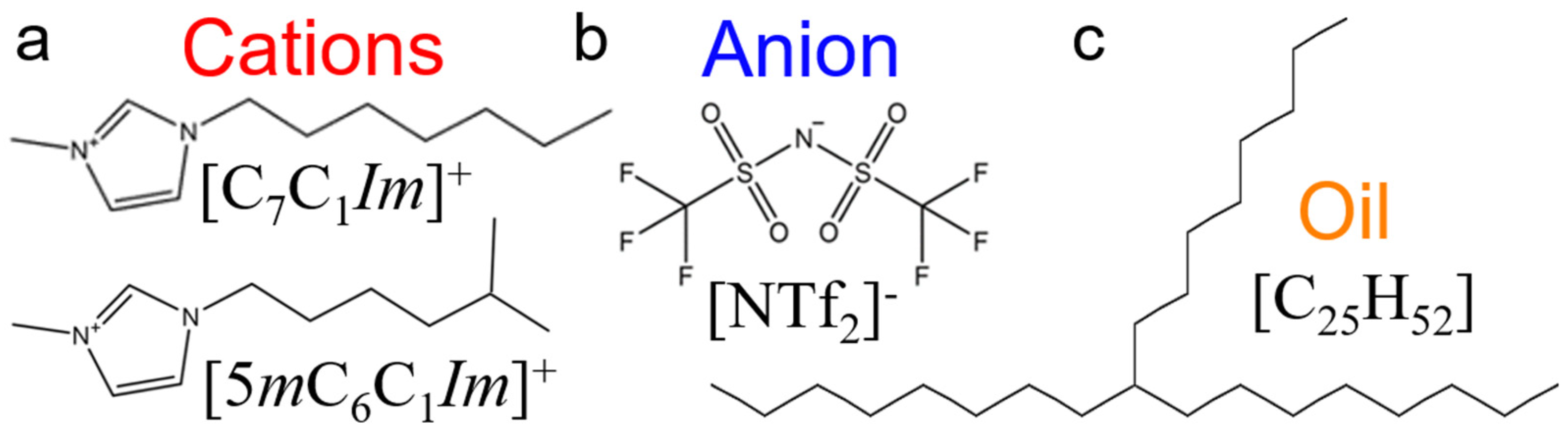
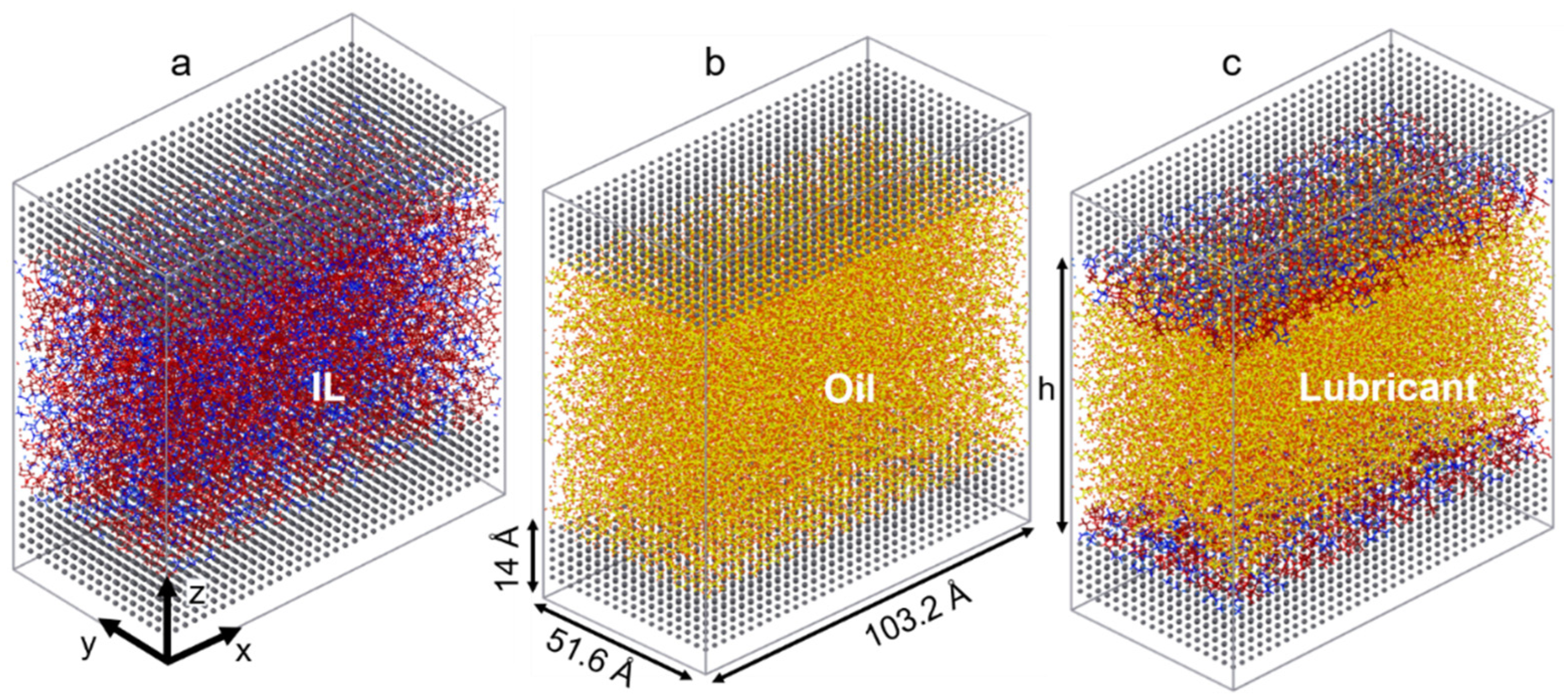
2.1. Simulations Preparation and Force Field

The ILs chosen for this study consist of two imidazolium-based cations with long linear and branched alkyl chains (1-heptyl-3-methylimidazolium [C7C1Im]+ and 1-(5-methylhexyl)-3-methylimidazolium [5mC6C1Im]+), each coupled with an oxidatively stable anion (bis[(trifluoroethane)sulfonyl]imide [NTf2]). As a model oil with a low friction coefficient, a branched alkane (9-octylheptadecane [C25H52]) is used to simulate pure conventional fuel behavior. The chemical structures of the molecules studied are shown in Figure 1. The liquids are confined between two identical surfaces, each made of 6480 α-iron (Fe) atoms [61]. The area of the solid-liquid interface is 5325 Å, and the height of the metal slab is 14 Å (roughly the thickness of 10 atomic layers). Four different confined systems are studied: IL with linear alkyl chain cation (linear IL), IL with branched alkyl cation (branched IL), 9-octylheptadecane, and a mixture of linear IL and oil (i.e., lubricant). Both the linear and branched ILs-Fe systems size is 51,180 atoms while the oil-Fe is 63,472 atoms. The target fraction of ILs in oil is calculated based on the number of ion pairs required to fully cover the metal surfaces. The mixed system is created by placing the IL with linear cation directly on the upper and lower interfaces and filling up the bulk with oil molecules (see Figure 2c). Here, the system size is 65,376 atoms, out of which 11,760 are IL atoms.
The general AMBER force field is used as a model for the inter- and intramolecular interactions present in the liquids [62,63,64]. Optimization of isolated ion structures of ILs is performed using the B3LYP/6-311++g(d,p) level through Gaussian 09 software [65]. The RESP method is used to assign partial charges with a rescaling factor of 0.8 to account for the polarizability and charge transfer presence in ions [66]. Such rescaling has been shown to predict ILs bulk properties that agree with experimental observations [67,68]. Additionally, the bulk properties of these ionic liquids were explored in previous research [69]. For the 9-octylheptadecane, the atom charges were assigned using the AM1-BCC method [70,71]. Intermolecular potentials for ILs and 9-octylheptadecane interfacial systems are calculated using the 12–6 Lennard-Jones (LJ) potential. The Fe-Fe interactions are simulated using the embedded atom method (EAM) [72,73], while cross interactions between atoms of liquids and iron are represented by LJ. The remaining interactions are computed by mixing rules [74,75]. The exact LJ cross parameters used in this study are listed in our previous work [60,61,76,77]. Both Coulombic and LJ interactions are computed up to a cutoff distance of 12 Å. Long-range interactions are approximated using the particle-particle particle-mesh (PPPM) algorithm and tail correction [78]. Periodic boundary conditions are applied in the x and y directions, while the boundary condition is fixed in the direction of confinement (z-axis). However, to properly account for electrostatic interactions in the z-direction, a volume equivalent to three empty simulation boxes is introduced between the metal slabs, thus eliminating potential slab-slab interactions (e.g., slab correction implementation). All of the simulations are run in LAMMPS using a time step of 1 fs [79].
To confine the liquids between the iron slabs and introduce various degrees of confinement, constant velocities are symmetrically applied towards the center of the simulation boxes to both upper and lower surfaces. In this way, the systems are uniformly compressed. It is important to note that the velocity for the compression has to be relatively slow to allow the molecules to have enough time to evolve and orient accordingly under the applied pressure.
To study the equilibrium dynamics of the systems, microcanonical ensemble (NVE) simulations are performed at a temperature of 450 K using a Langevin thermostat with a damping factor of 100 [80,81]. At this stage of system preparation, the iron atoms do not undergo any dynamics. The degree of confinement is controlled by the final gap size between the metal slabs, which can be varied with simulation run time: the longer the simulation run, the more confinement (smaller gap size) is introduced. Once the compression is complete, the systems are equilibrated in the same Langevin thermostat (T = 450 K) and NVE conditions. The normal force exerted by the liquids on both top and bottom solid surfaces is computed and recorded every 50 ps averaged over each time step. The simulation runtime was in the range of 3–10 ns. The end time was chosen as the time at which the recorded force reaches a steady state and equal values at both slabs, plus an additional 1 ns to ensure equilibration. Typically, the more pressure that was applied, the longer it took for the system to relax. The values of the pressure for all four systems were around 0.2 GPa, 0.5 GPa, and 1 GPa. All the experimental conditions are listed in Table 1.
Density profiles along the z-direction are computed by averaging density data over the last 1 ns of the equilibrium simulation. The final relaxed structures are presented in Figure 2.

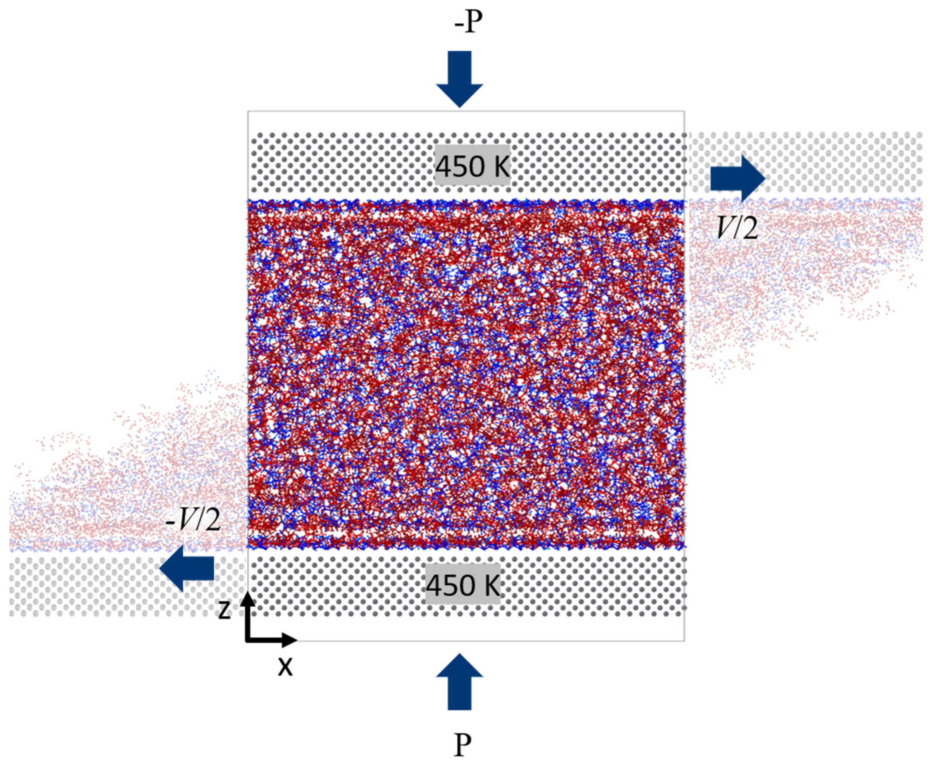
2.2. Shear Simulations Details

After the systems were relaxed, shear simulations were performed by sliding the explicit walls. The walls are set to move in opposite directions along the x-axis with the constant velocity V/2 (refer to Figure 3). The shear velocities chosen are V1 = 10 m/s, V2 = 20 m/s, V3 = 50 m/s, and V4 = 100 m/s. The various degrees of confinement are maintained throughout the simulation in the systems by applying normal force (or pressure P) on the metal slabs. This is accomplished by dividing the force (calculated from the equilibrium simulations) by the number of atoms (Fatom) in the slab and adding the resulting value uniformly on each Fe atom of the bottom slab. Similarly, -Fatom is the applied force at the top slab. For these simulations, only the metal slabs are kept at a constant temperature of 450 K using a Langevin thermostat. Non-equilibrium molecular dynamics are performed by solving Newton’s equations of motion in NVE ensemble to shear the fluids: r ˙ i = p i / m i and p ˙ i = U / r i , where r i is the position of particle i , p i is thermal momentum, m i is mass of the particle, and U is system potential. The periodic boundary conditions are applied in x and y directions, and z is the direction of confinement. The liquids dynamics are computed using an NVE ensemble allowing the temperature of the liquid to evolve freely. In these simulations, the momentum is transferred from the walls into the fluid phase according to the established force field to determine the boundary behavior of the velocity of fluids, and there is no artificial coupling between the velocity of the walls and the confined fluid. The simulation run time is set to 5 ns for all of the systems. Velocity profiles and density profiles are also recorded during the simulations. Data are collected at analyzed after the system reaches a steady state (typically the last 4 ns of the run). Lastly, the time averages of shear force (Fx in the x-direction) and normal force (Fy in the y-direction) of the molecules exerting on the surface are computed and recorded every 100 ps. The schematic of the shear simulation is shown in Figure 3.
All simulations are run under an elevated temperature of 450 K, at a range of external pressures applied to the confined liquids, and at various shear rates to simulate realistic and extreme operational conditions [82,83,84].

3. Results and Discussion

In this section, we report the results and carry on discussions about the effect of various degrees of confinement on the molecular structuring, behavior of liquids under shear flow of different strengths, and tribological properties of two types of imidazolium-based ionic liquid [C7C1Im]+[NTf2] (linear IL) and [5mC6C1Im]+[NTf2] (branched IL) as well as branched alkane oil [C25H52] and a mixture of linear IL and oil. The preformed equilibrium simulations reveal complex restructuring of the IL molecules at the metal surface that was previously identified as the main contributor to the stability of the interfacial layer [60]. The shear simulations provide insights into tribological capabilities of the proposed IL-based lubricant to enable the inverse design of such lubricating materials.

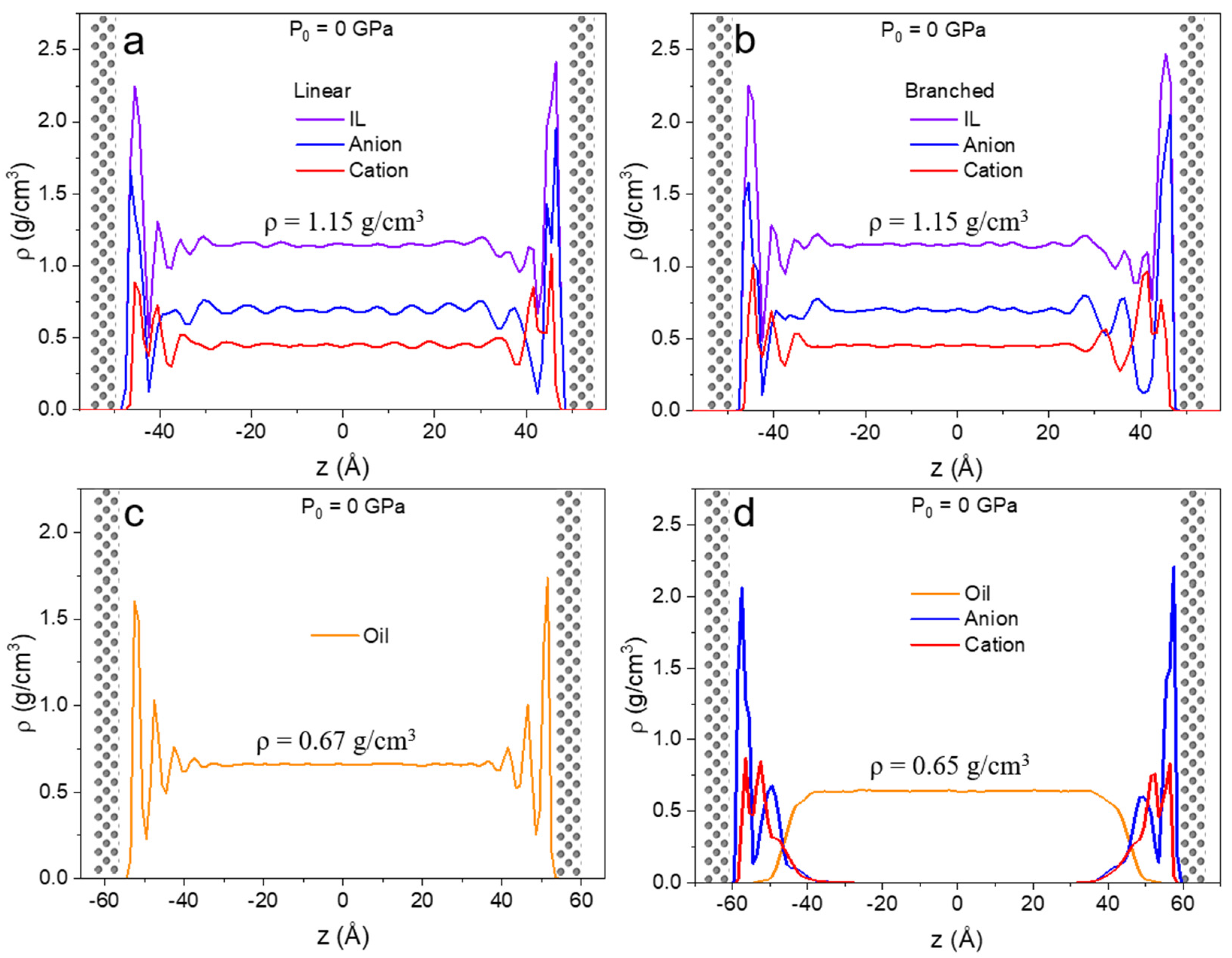
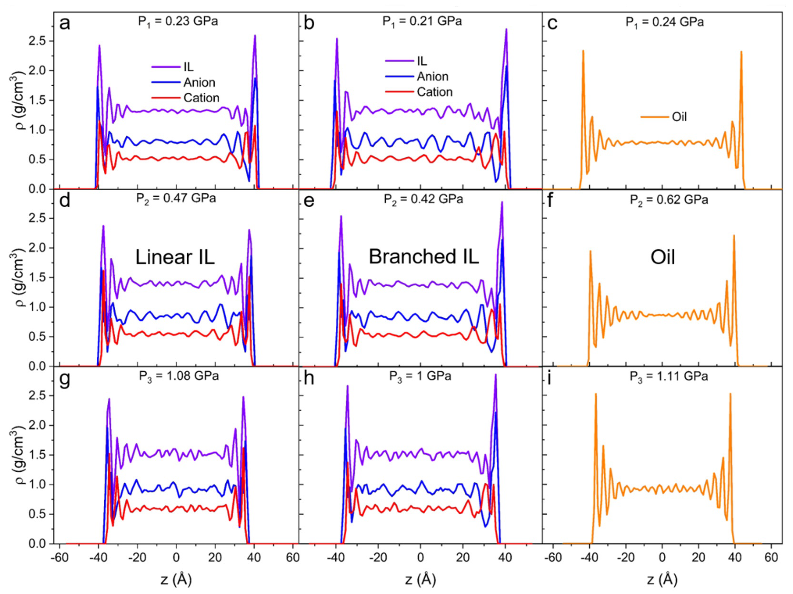
3.1. Density Profiles

In Figure 4, the density profiles along confinement direction z for the unpressurized case are shown for all four liquids. The introduction of the metal surfaces with no external forces acting on the system gives rise to multilayer formation at both lower and upper walls. This is in agreement with IL behavior reported in previous studies [60]. This type of restructuring is due to the interaction between the liquid and solid atoms of the surface [11]. In the case of linear and branched ILs (Figure 4a,b), the first interfacial layer is mainly populated by anions, but some cations are present at the surface as well. The second layer mainly consists of cations. Due to the symmetric nature of the [NTf2] anion, it arranges tightly on the surface.
The density profile of the oil show at least three distinguishable layers at the iron surface after which no additional fluctuations are observed. The density profile of the mixture of linear IL and oil (Figure 4d) displays two high intensity peaks for anion and cation and no vivid peaks at the IL-oil interface. Moreover, the anion’s first density peak has a higher intensity than in the pure IL system. Here, higher ordering is anticipated because ions experience confinement not only from the metal slab but also from the liquid-liquid interface formed with oil. There is a small overlap between liquid-liquid phases, but no significant penetration of ions into the oil phase is observed. The phase separation of imidazolium-based ILs and model oil have been previously reported [85]. Lastly, due to their distance from the surface, no interfacial phenomena are detected in the oil molecules.
Interestingly, oil densities in the bulk region in pure (ρ = 0.670 ± 0.003 g/cm3) and lubricant (ρ = 0.648 ± 0.007 g/cm3) cases differ by 3%. This can be due to the discrepancy in the load distribution of the more densely packed ions on the surface than 9-octylheptadecane molecules; hence the oil experiences less pressure. All the densities in bulk at zero pressure and at high pressures are relative to what can be found in literature after extrapolation to the elevated temperature of 450 K (see Table 2 for bulk density values under high degrees of confinement) [69,86,87].
At higher pressures, the intensity of density and its behavior change. Both linear (Figure 5a,d,g) and branched (Figure 5b,e,h) ILs show a closely packed first interfacial layer. The density values in all the additional layers grow with increasing degrees of confinement. Generally, in comparison to linear IL, branched IL systems exhibit higher values of density in the initial peak and lower values for any subsequent peak. Most importantly, with the increase of external load on the IL systems, the first density peak of the cation shifts outside of the first anion peak. It means that the layer at the solid interface becomes mostly populated by anions and the next layer becomes mostly populated by cations. This anion-cation structure is called a double layer (or electrical double layer) and it usually occurs at charged surfaces [88,89,90]. In our case, the asymmetrical bulky cations get “squeezed out” due to the entropic effect. The anion of choice for this study ([NTf2]) is known to show low corrosiveness and great thermo-oxidative stability on metal surfaces [34]. Additionally, these anions form a stable layer on the iron surface, hence the anticorrosive protective layer is formed on the surface. The bulk density increases with the load for all systems as can be seen in Table 2 and Figure 5. It also reveals higher amplitude density oscillations than in unpressurized systems.
In the case of the highest applied pressure on the oil system (Figure 5i), the amplitude of density oscillations in the bulk region is four times higher than for the system with no external pressure on the metal slabs. This suggests that under high normal load, oil clusters are present not only at the interface but also in bulk, indicating that the oil starts to solidify. This phenomenon is frequently reported in experiments and modeling studies of the tribology of hydrocarbons [91,92]. Subjecting such highly confined liquid to shear can lead to dry friction due to separation and transverse flow, which can become a significant drawback of oil lubricants [5].
The density fluctuations of the oil bulk in the unpressurized system (Figure 4c) can be attributed to the thermal fluctuations, which are within the statistical error (~1%). In the equilibrium simulations, the temperature of the liquid is controlled. As pressure increases, the oil system starts to experience an interesting density behavior. When no load is applied, the first density peak is observed at ρ = 1.7 g/cm3 and at least three additional layers are seen (Figure 4c). At P1 = 0.24 GPa (Figure 5c), the first peak is recorded at ρ = 2.4 g/cm3 and an additional three or four layers are observed. At P2 = 0.62, the first peak is recorded at ρ = 2.2 g/cm3 and six additional layers are present. Finally, at P3 = 1.11 GPa (Figure 5i), the density at the surface reaches 2.5 g/cm3, and the layers propagate throughout the whole system. This behavior implies that the liquid prefers to rearrange into more ordered clusters over increasing the packing density at the interface.
Figure 6 shows the density profile of the lubricant system (IL linear and oil). Two prominent anion peaks as well as two peaks and a shoulder peak are present for the cation case. In comparison with the unpressurized case, the system with the highest degree of confinement has a more pronounced structuring between cation and oil molecules. The oil also experiences an increase in density at the liquid-liquid interface with the applied load. The number of IL layers does not change with the applied pressure. Like the pure system, the bulk density of oil at high pressure shows the propagation of layering throughout the bulk (Figure 6d).

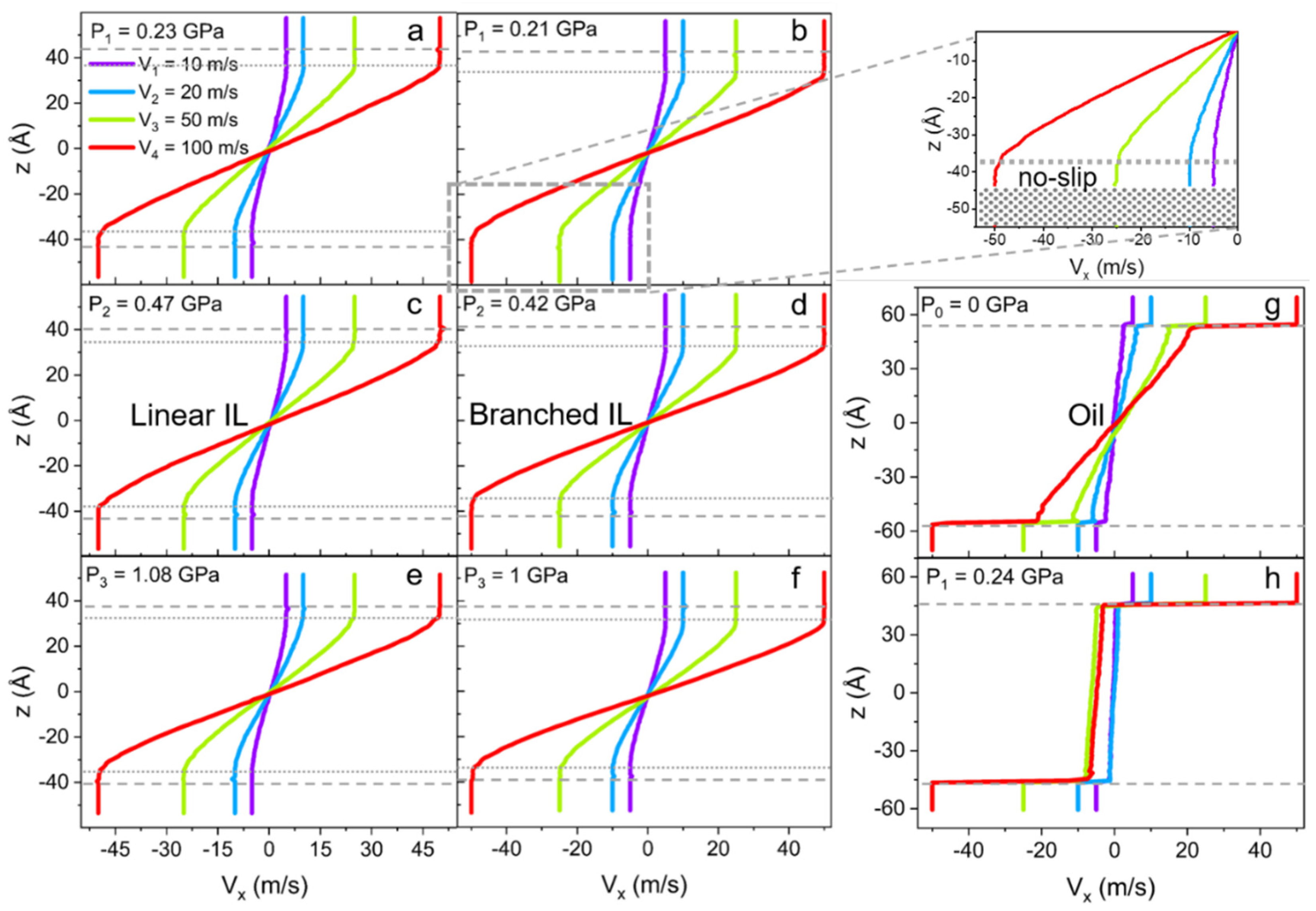
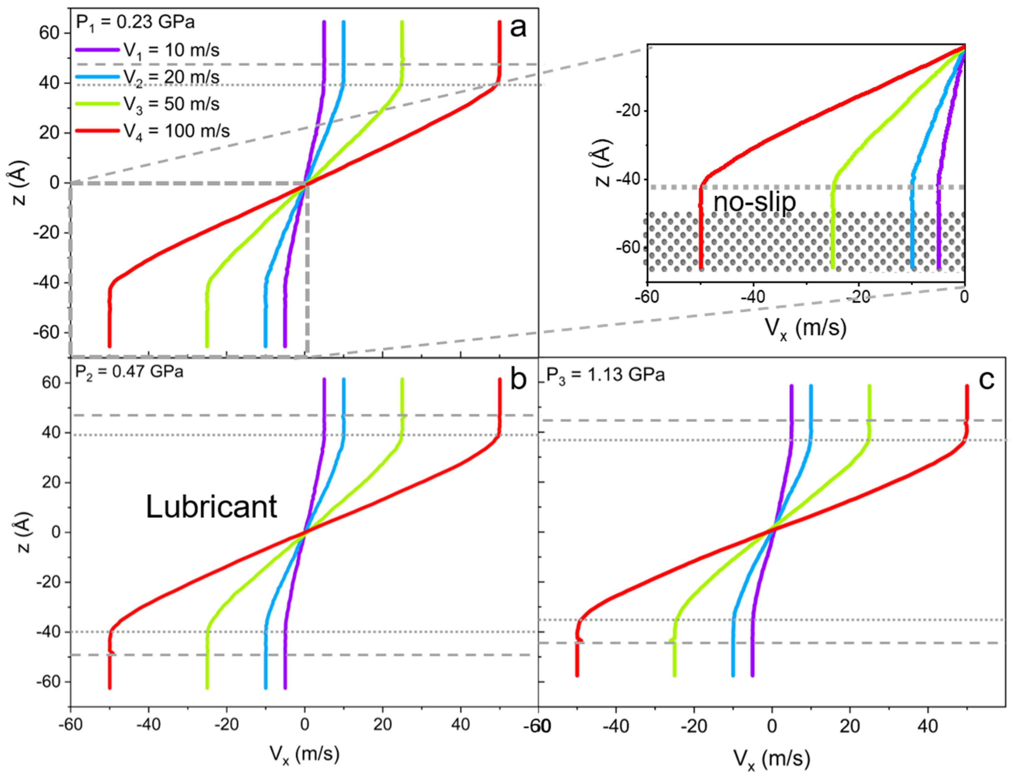
3.2. Velocity Profiles

Velocity profiles (Vx), as a function of the z-coordinate of linear and branched ILs, are plotted in Figure 7a–f. Four different velocities are applied to the metal walls to access the liquid response over a range of shear rates. The data reveal no-slip boundary conditions at the solid-liquid interface for ILs. However, even though the velocity profiles seem to follow linear Couette flow behavior, this is only true for the bulk of the liquids. The phenomenon is called central localization (a specific case of shear banding) when interfacial layers of liquid move with the solid walls as if these layers are a continuation of it [93,94,95,96]. Hence, the no-slip condition is extended to the ordered ion structures present on the surface. This phenomenon of central localization is observed due to the high stability of the IL layer on the surface, even under nano-confinement and high share rate conditions [97,98,99,100].
It is also found that the branching of the cation alkyl chain affects the “no-slip” or “frozen” layer thickness. In fact, for linear IL the interfacial layer is 5–6 Å thick, compared to the 8 Å layer in the branched IL at P1. However, at the highest pressure P3, the layering thickness of the branched IL is reduced to 6 Å. This difference can be due to the packing size of the branched molecules being slightly larger than the packing size of linear ones. In other words, the radius of gyration of branched cations is bigger than the radius of gyration of linear cations until the pressure is high enough to compress both types of molecules and reduce the difference in size. Furthermore, these size scales are relative to the thickness of ionic liquids’ double layers and consistent with other reported data [95]. The oil system (Figure 7g,h) shows a large slip, as expected [101]. Other observations from these shear simulations propose that the bulk density fluctuations smoothen out at high shear rates due to the active rearrangement of molecules by the induced flow. These dynamics contribute to the reduction of crystallization of the liquids in bulk under confinement. The density and the number of layers at the surface stay the same as in equilibrium simulations.
For the lubricant system, due to the high free energy of adsorption of ILs on the iron surface, the slip of liquid is reduced regardless of the applied load (see Figure 8). This phenomenon has relevant industrial applications as it allows for the decreasing of wear in the machinery by preventing dry lubrication and the splitting of the oil, and slows down the oxidation of the metal surfaces. It was also observed that single cations split from the IL cluster into the oil phase when the highest degrees of confinement and largest wall velocities were applied. Yet, the first interfacial layer always remains intact.

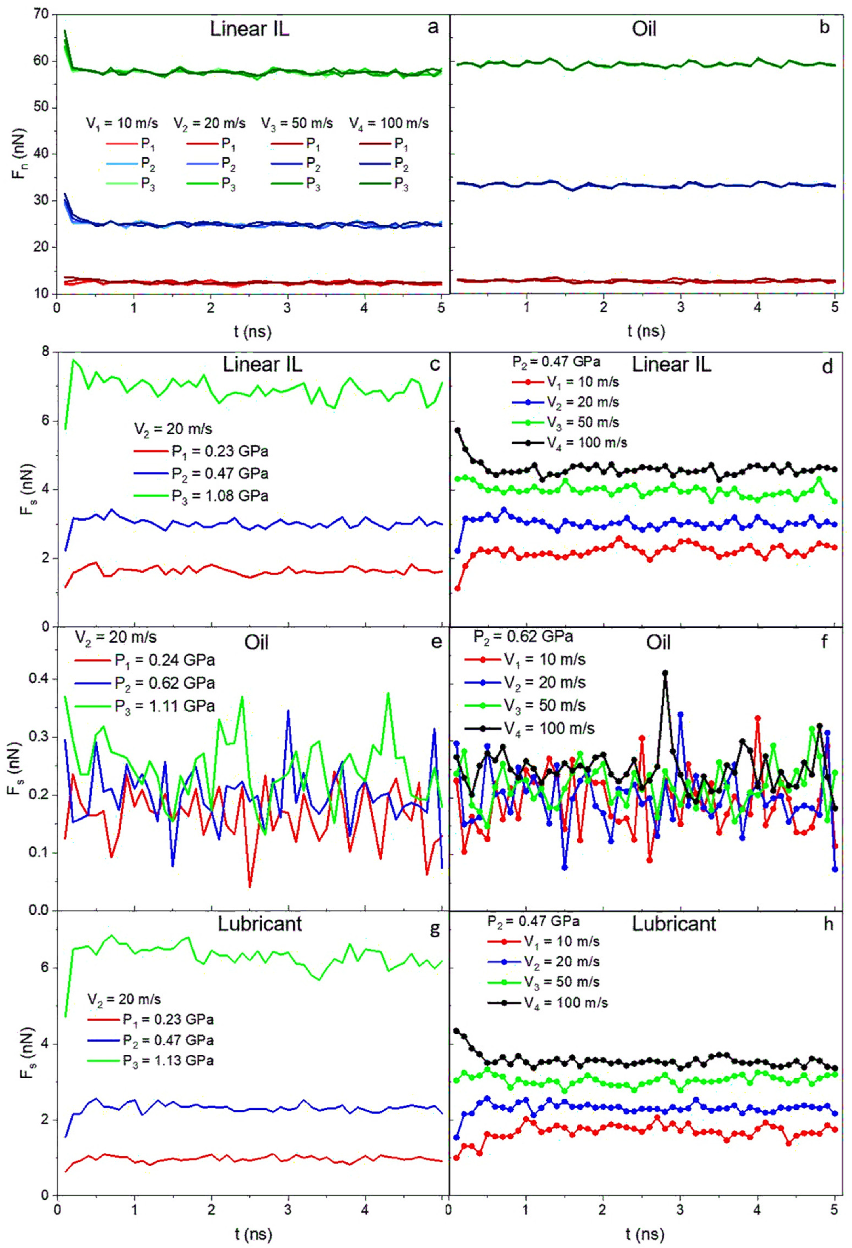
3.3. Tribological Properties

The next step is to verify whether using ILs additives to conventional lubricants can lead to a friction reduction in the system. In Figure 9a,b, as anticipated, the normal forces (Fn) exerted by the walls on the liquid depend on the pressure applied and are independent of the velocity. On the other hand, the shear forces (Fs) for ILs and lubricant systems (Figure 9c,d,g,h) show dependency on both velocity and pressure. The data for oil are highly noisy, and after averaging it over time, a weak velocity dependence but strong pressure dependence is detected. Both normal and shear forces for all systems reach constant values over the simulation run time.
Friction coefficients are calculated using μ = F s F n and plotted in Figure 10, where they are presented as a function of pressure (Figure 10a–d) and shear velocity (Figure 10e–h). At low values of pressure, the difference between friction coefficients in the range of shear velocities is more prominent. At higher pressures, almost no variance is observed due to the structuring of the molecules in the liquids. This is consistent with the density and velocity profile data. An increase in the friction coefficient with increasing pressure in a low velocity regime is identified for pure ILs and mixture systems. The opposite happens for a high sliding velocity regime (20–50 m/s), where the friction coefficient decreases with applied load. A general trend of friction coefficient increase with high shearing rates is seen for all the systems. The 9-octylheptadecane as low friction model oil shows the lowest friction coefficients at P1 = 0.24 GPa and P2 = 0.62 GPa. A jump in friction coefficient values occurs at the highest loads and velocity due to the oil solidification.
The mixed IL and oil system shows lower friction coefficient values at all applied loads than that of pure ILs (~0.12 and below for lower shear rates—see Table 3). To the best of our knowledge, this low friction coefficient value has yet to be achieved by pure ILs lubricants in contact with neutral metals at such high pressures and temperatures. The rest of the velocities show similar behavior that proves that imidazolium-based ILs can function as an efficient additive that can reduce wear by excluding dry lubrication and surface oxidation while maintaining the low friction that is introduced by model oils.

4. Conclusions

To better elucidate the lubrication properties of ILs and their mixture with conventional oil under metal confinement, all-atomistic molecular dynamics simulations are performed in this study. A series of microstructural and tribological predictions on pure ILs (1-heptyl-3-methylimidazolium and 1-(5-methylhexyl)3-ethylimidazolium cations, and bis[(trifluoroethane)sulfonyl]imide anion), pure oil (9-octylheptade-cane), and IL-oil mixture are presented. Both equilibrium and shear studies under different applied loads are performed. For all of the systems, the density profiles under equilibrium conditions and no external load reveal the formation of a layered structure at the solid-liquid interface. When external loads are applied to the system, the formation of a double layer of ILs is observed. In addition, the density values of all the layers increase with the degrees of confinement. At high applied pressures, the oil solidified. The mixture of IL and oil shows two layers of anion and cation and a low intensity additional density peak indicated a weak interface between the cations and oil molecules. For all IL-containing systems under high applied pressure, the interfacial layer primarily consists of anions. The formed anion layer protects the iron surface from corrosion due to the oxidatively stable nature of the chosen anion.
Velocity profiles reveal the presence of no-slip boundary conditions at the solid-liquid interface of ILs and through the first double layer of ions. The linear velocity profile in the bulk of the liquids indicates central localization of shear in the ILs systems. As expected, oil exhibited a large slip. When IL is added to the oil, the high free energy of adsorption of ILs on the iron surface helps to reduce the slip in the system. Normal and shear forces are also calculated and used to obtain the friction coefficient of the various configurations studied. Pure ILs systems displayed the highest friction coefficient, making them unideal lubrication candidates. However, when used as additives to conventional oil, a decrease in the friction coefficient is observed in comparison to pure ILs. In addition to the anion protective layer on the metal surface, these findings suggest that ILs as additives to conventional oils are better candidates for the next generation of high-performance and noncorrosive lubricants than pure ionic liquids.
In this work, we explored ILs and IL-based lubricants at elevated temperature conditions. Meanwhile, low-temperature lubrication is just as important in machinery [102]. ILs are expected to perform well due to their excellent thermal stability in both high and low-temperature regimes. Nevertheless, investigating the behavior of ILs at low temperatures is still crucial for understanding the full capability of the proposed lubricant. Moreover, surface irregularity results in a reduction of the ordering of the lubricant at the surface and might increase the overall friction and wear in lubricating systems [12,103,104]. The Gibbs free energy of the adsorption of molecules varies with the surface selection [77]. Henceforth, surface altercations such as chemical composition and nano roughness can influence the properties of a lubricant and should be studied to give a complete picture of IL tribological performance.

Author Contributions

Conceptualization, D.L. and F.K.; methodology, D.L. and F.K.; writing—original draft preparation, D.L.; writing—review and editing, D.L. and F.K.; visualization, D.L.; supervision, F.K. All authors have read and agreed to the published version of the manuscript.

Funding

This research received no external funding.

Institutional Review Board Statement

Not applicable.

Informed Consent Statement

Not applicable.

Data Availability Statement

The data that support the findings of this study are available from the corresponding author upon reasonable request.

Conflicts of Interest

The authors declare that they have no conflict of interest.

References

  1. Cai, M.; Guo, R.; Zhou, F.; Liu, W. Lubricating a bright future: Lubrication contribution to energy saving and low carbon emission. Sci. China Technol. Sci. 2013, 56, 2888–2913. [Google Scholar] [CrossRef]
  2. Sasaki, S. Environmentally friendly tribology (Eco-tribology). J. Mech. Sci. Technol. 2010, 24, 67–71. [Google Scholar] [CrossRef]
  3. Baumann, A.; Bertsche, B. Coefficient of friction behavior of gear oils and significance for the meshing process of spur gears. Forsch. Ing. 2022, 86, 795–805. [Google Scholar] [CrossRef]
  4. Wang, W.; Li, P.; Sheng, S.; Tian, H.; Zhang, H.; Zhang, X. Influence of Hydrocarbon Base Oil Molecular Structure on Lubricating Properties in Nano-scale Thin Film. Tribol. Lett. 2019, 67, 111. [Google Scholar] [CrossRef]
  5. Lugt, P.M. Grease Lubrication in Rolling Bearings; John Wiley & Sons: Hoboken, NJ, USA, 2012. [Google Scholar]
  6. Askwith, T.C.; Cameron, A.; Crouch, R.F.; Saunders, O.A. Chain length of additives in relation to lubricants in thin film and boundary lubrication. Proc. R. Soc. Lond. Ser. A Math. Phys. Sci. 1966, 291, 500–519. [Google Scholar] [CrossRef]
  7. Kajdas, C.; Makowska, M.; Gradkowski, M. Tribochemistry of n-hexadecane in different material systems. Lubr. Sci. 2006, 18, 255–263. [Google Scholar] [CrossRef]
  8. Kajdas, C.; Makowska, M.; Gradkowski, M. Influence of temperature on the tribochemical reactions of hexadecane. Lubr. Sci. 2003, 15, 329–340. [Google Scholar] [CrossRef]
  9. Makowska, M.; Kajdas, C.; Gradkowski, M. Mechanism of boundary film formation from n-hexadecane. Lubr. Sci. 2004, 16, 101–110. [Google Scholar] [CrossRef]
  10. Montmitonnet, P.; Delamare, F.; Rizoulieres, B. Transfer layer and friction in cold metal strip rolling processes. Wear 2000, 245, 125–135. [Google Scholar] [CrossRef]
  11. Gao, J.; Luedtke, W.; Landman, U. Structure and solvation forces in confined films: Linear and branched alkanes. J. Chem. Phys. 1997, 106, 4309–4318. [Google Scholar] [CrossRef]
  12. Gao, J.; Luedtke, W.; Landman, U. Structures, solvation forces and shear of molecular films in a rough nano-confinement. Tribol. Lett. 2000, 9, 3–13. [Google Scholar] [CrossRef]
  13. Jabbarzadeh, A.; Harrowell, P.; Tanner, R. Low friction lubrication between amorphous walls: Unraveling the contributions of surface roughness and in-plane disorder. J. Chem. Phys. 2006, 125, 034703. [Google Scholar] [CrossRef] [PubMed]
  14. Tamura, H.; Yoshida, M.; Kusakabe, K.; Young-Mo, C.; Miura, R.; Kubo, M.; Teraishi, K.; Chatterjee, A.; Miyamoto, A. Molecular dynamics simulation of friction of hydrocarbon thin films. Langmuir 1999, 15, 7816–7821. [Google Scholar] [CrossRef]
  15. Cui, S.; Cummings, P.; Cochran, H. Molecular simulation of the transition from liquidlike to solidlike behavior in complex fluids confined to nanoscale gaps. J. Chem. Phys. 2001, 114, 7189–7195. [Google Scholar] [CrossRef]
  16. Zheng, X.; Zhu, H.; Kosasih, B.; Tieu, A.K. A molecular dynamics simulation of boundary lubrication: The effect of n-alkanes chain length and normal load. Wear 2013, 301, 62–69. [Google Scholar] [CrossRef]
  17. Jabbarzadeh, A.; Harrowell, P.; Tanner, R. Very low friction state of a dodecane film confined between mica surfaces. Phys. Rev. Lett. 2005, 94, 126103. [Google Scholar] [CrossRef]
  18. Jabbarzadeh, A.; Harrowell, P.; Tanner, R. Crystal Bridges, Tetratic Order, and Elusive Equilibria: The Role of Structure in Lubrication Films; ACS Publications: Washington, DC, USA, 2007; Volume 111, pp. 11354–11365. [Google Scholar]
  19. Jabbarzadeh, A.; Atkinson, J.D.; Tanner, R.I. The effect of branching on slip and rheological properties of lubricants in molecular dynamics simulation of Couette shear flow. Tribol. Int. 2002, 35, 35–46. [Google Scholar] [CrossRef]
  20. Berro, H.; Fillot, N.; Vergne, P. Molecular dynamics simulation of surface energy and ZDDP effects on friction in nano-scale lubricated contacts. Tribol. Int. 2010, 43, 1811–1822. [Google Scholar] [CrossRef]
  21. Kaur, G.; Kumar, H.; Singla, M. Diverse applications of ionic liquids: A comprehensive review. J. Mol. Liq. 2022, 351, 118556. [Google Scholar] [CrossRef]
  22. Song, J. Research Progress of Ionic Liquids as Lubricants. ACS Omega 2021, 6, 29345–29349. [Google Scholar] [CrossRef] [PubMed]
  23. Wu, J.; Zhu, J.; Mu, L.; Shi, Y.; Dong, Y.; Feng, X.; Lu, X. High load capacity with ionic liquid-lubricated tribological system. Tribol. Int. 2016, 94, 315–322. [Google Scholar] [CrossRef]
  24. Liu, X.; Zhou, F.; Liang, Y.; Liu, W. Tribological performance of phosphonium based ionic liquids for an aluminum-on-steel system and opinions on lubrication mechanism. Wear 2006, 261, 1174–1179. [Google Scholar] [CrossRef]
  25. Ueno, K.; Kasuya, M.; Watanabe, M.; Mizukami, M.; Kurihara, K. Resonance shear measurement of nanoconfined ionic liquids. Phys. Chem. Chem. Phys. 2010, 12, 4066–4071. [Google Scholar] [CrossRef] [PubMed]
  26. Zhou, F.; Liang, Y.; Liu, W. Ionic liquid lubricants: Designed chemistry for engineering applications. Chem. Soc. Rev. 2009, 38, 2590–2599. [Google Scholar] [CrossRef] [PubMed]
  27. Xiao, H.; Guo, D.; Liu, S.; Pan, G.; Lu, X. Film thickness of ionic liquids under high contact pressures as a function of alkyl chain length. Tribol. Lett. 2011, 41, 471–477. [Google Scholar] [CrossRef]
  28. Verma, C.; Quraishi, M.A. Ionic liquids-metal surface interactions: Effect of alkyl chain length on coordination capabilities and orientations. E-Prime—Adv. Electr. Eng. Electron. Energy 2022, 2, 100070. [Google Scholar] [CrossRef]
  29. Jiang, H.; Yu, Y.; Tang, W.; Zhou, R.; Shi, W.; Bai, L. A molecular dynamics study on the lubrication performance of ionic liquids. J. Mater. Sci. 2022, 57, 18874–18888. [Google Scholar] [CrossRef]
  30. Jin, C.-M.; Ye, C.; Phillips, B.S.; Zabinski, J.S.; Liu, X.; Liu, W.; Jean’ne, M.S. Polyethylene glycol functionalized dicationic ionic liquids with alkyl or polyfluoroalkyl substituents as high temperature lubricants. J. Mater. Chem. 2006, 16, 1529–1535. [Google Scholar] [CrossRef]
  31. Mirkhani, S.A.; Gharagheizi, F.; Ilani-Kashkouli, P.; Farahani, N. Determination of the glass transition temperature of ionic liquids: A molecular approach. Thermochim. Acta 2012, 543, 88–95. [Google Scholar] [CrossRef]
  32. Liu, J.; Wang, F.; Zhang, L.; Fang, X.; Zhang, Z. Thermodynamic properties and thermal stability of ionic liquid-based nanofluids containing graphene as advanced heat transfer fluids for medium-to-high-temperature applications. Renew. Energy 2014, 63, 519–523. [Google Scholar] [CrossRef]
  33. Minami, I.; Kamimura, H.; Mori, S. Thermo-oxidative stability of ionic liquids as lubricating fluids. J. Synth. Lubr. 2007, 24, 135–147. [Google Scholar] [CrossRef]
  34. Pisarova, L.; Gabler, C.; Dörr, N.; Pittenauer, E.; Allmaier, G. Thermo-oxidative stability and corrosion properties of ammonium based ionic liquids. Tribol. Int. 2012, 46, 73–83. [Google Scholar] [CrossRef]
  35. Amiril, S.A.S.; Rahim, E.A.; Syahrullail, S. A review on ionic liquids as sustainable lubricants in manufacturing and engineering: Recent research, performance, and applications. J. Clean. Prod. 2017, 168, 1571–1589. [Google Scholar] [CrossRef] [Green Version]
  36. Somers, A.E.; Howlett, P.C.; MacFarlane, D.R.; Forsyth, M. A review of ionic liquid lubricants. Lubricants 2013, 1, 3–21. [Google Scholar] [CrossRef] [Green Version]
  37. Cai, M.; Yu, Q.; Liu, W.; Zhou, F. Ionic liquid lubricants: When chemistry meets tribology. Chem. Soc. Rev. 2020, 49, 7753–7818. [Google Scholar] [CrossRef]
  38. Minami, I. Ionic liquids in tribology. Molecules 2009, 14, 2286–2305. [Google Scholar] [CrossRef] [Green Version]
  39. Palacio, M.; Bhushan, B. A review of ionic liquids for green molecular lubrication in nanotechnology. Tribol. Lett. 2010, 40, 247–268. [Google Scholar] [CrossRef]
  40. Perkin, S. Ionic liquids in confined geometries. Phys. Chem. Chem. Phys. 2012, 14, 5052–5062. [Google Scholar] [CrossRef]
  41. Arias-Pardilla, J.; Espinosa, T.; Bermudez, M. Electrochemistry in Ionic Liquids; Springer: Berlin/Heidelberg, Germany, 2015. [Google Scholar]
  42. Qu, J.; Truhan, J.; Dai, S.; Luo, H.; Blau, P. Ionic liquids with ammonium cations as lubricants or additives. Tribol. Lett. 2006, 22, 207–214. [Google Scholar] [CrossRef]
  43. Jiménez, A.; Bermúdez, M.; Carrion, F.; Martinez-Nicolas, G. Room temperature ionic liquids as lubricant additives in steel–aluminium contacts: Influence of sliding velocity, normal load and temperature. Wear 2006, 261, 347–359. [Google Scholar] [CrossRef]
  44. Jiménez, A.-E.; Bermúdez, M.-D. Imidazolium ionic liquids as additives of the synthetic ester propylene glycol dioleate in aluminium–steel lubrication. Wear 2008, 265, 787–798. [Google Scholar] [CrossRef]
  45. Mistry, K.; Fox, M.; Priest, M. Lubrication of an electroplated nickel matrix silicon carbide coated eutectic aluminium—Silicon alloy automotive cylinder bore with an ionic liquid as a lubricant additive. Proc. Inst. Mech. Eng. Part J J. Eng. Tribol. 2009, 223, 563–569. [Google Scholar] [CrossRef]
  46. Schneider, A.; Brenner, J.; Tomastik, C.; Franek, F. Capacity of selected ionic liquids as alternative EP/AW additive. Lubr. Sci. 2010, 22, 215–223. [Google Scholar] [CrossRef]
  47. Lu, R.; Nanao, H.; Kobayashi, K.; Kubo, T.; Mori, S. Effect of lubricant additives on tribochemical decomposition of hydrocarbon oil on nascent steel surfaces. J. Jpn. Pet. Inst. 2010, 53, 55–60. [Google Scholar] [CrossRef] [Green Version]
  48. Yao, M.; Liang, Y.; Xia, Y.; Zhou, F. Bisimidazolium Ionic Liquids as the High-performance antiwear additives in poly (ethylene glycol) for steel−steel contacts. ACS Appl. Mater. Interfaces 2009, 1, 467–471. [Google Scholar] [CrossRef] [PubMed]
  49. Cai, M.; Liang, Y.; Yao, M.; Xia, Y.; Zhou, F.; Liu, W. Imidazolium ionic liquids as antiwear and antioxidant additive in poly (ethylene glycol) for steel/steel contacts. ACS Appl. Mater. Interfaces 2010, 2, 870–876. [Google Scholar] [CrossRef]
  50. Qu, J.; Luo, H.; Chi, M.; Ma, C.; Blau, P.J.; Dai, S.; Viola, M.B. Comparison of an oil-miscible ionic liquid and ZDDP as a lubricant anti-wear additive. Tribol. Int. 2014, 71, 88–97. [Google Scholar] [CrossRef]
  51. Iglesias, P.; Bermúdez, M.; Carrión, F.; Martınez-Nicolás, G. Friction and wear of aluminium–steel contacts lubricated with ordered fluids-neutral and ionic liquid crystals as oil additives. Wear 2004, 256, 386–392. [Google Scholar] [CrossRef]
  52. Jiménez, A.; Bermúdez, M. Ionic liquids as lubricants of titanium–steel contact. Part 3. Ti6Al4V lubricated with imidazolium ionic liquids with different alkyl chain lengths. Tribol. Lett. 2010, 40, 237–246. [Google Scholar] [CrossRef]
  53. Itoh, T.; Watanabe, N.; Inada, K.; Ishioka, A.; Hayase, S.; Kawatsura, M.; Minami, I.; Mori, S. Design of alkyl sulfate ionic liquids for lubricants. Chem. Lett. 2009, 38, 64–65. [Google Scholar] [CrossRef]
  54. Minami, I.; Kita, M.; Kubo, T.; Nanao, H.; Mori, S. The tribological properties of ionic liquids composed of trifluorotris (pentafluoroethyl) phosphate as a hydrophobic anion. Tribol. Lett. 2008, 30, 215–223. [Google Scholar] [CrossRef]
  55. Wang, H.; Lu, Q.; Ye, C.; Liu, W.; Cui, Z. Friction and wear behaviors of ionic liquid of alkylimidazolium hexafluorophosphates as lubricants for steel/steel contact. Wear 2004, 256, 44–48. [Google Scholar] [CrossRef]
  56. Jiménez, A.; Bermúdez, M.; Iglesias, P.; Carrión, F.; Martínez-Nicolás, G. 1-N-alkyl-3-methylimidazolium ionic liquids as neat lubricants and lubricant additives in steel–aluminium contacts. Wear 2006, 260, 766–782. [Google Scholar] [CrossRef]
  57. Xie, G.; Luo, J.; Guo, D.; Liu, S. Nanoconfined ionic liquids under electric fields. Appl. Phys. Lett. 2010, 96, 043112. [Google Scholar] [CrossRef]
  58. Lopez Sanchez, F.; Otero, I.; Lopez, E.R.; Fernandez, J. Tribological properties of two bis (trifluoromethylsulfonyl) imide–based ionic liquids on steel–steel contact. Tribol. Trans. 2014, 57, 637–646. [Google Scholar] [CrossRef]
  59. Xia, Y.; Wang, S.; Zhou, F.; Wang, H.; Lin, Y.; Xu, T. Tribological properties of plasma nitrided stainless steel against SAE52100 steel under ionic liquid lubrication condition. Tribol. Int. 2006, 39, 635–640. [Google Scholar] [CrossRef]
  60. Lazarenko, D.; Khabaz, F. Interfacial dynamics and thermodynamics of imidazolium-based ionic liquids near iron surface. Langmuir 2022. submitted. [Google Scholar]
  61. Eder, S.J.; Vernes, A.S.; Betz, G. On the Derjaguin offset in boundary-lubricated nanotribological systems. Langmuir 2013, 29, 13760–13772. [Google Scholar] [CrossRef]
  62. Cornell, W.D.; Cieplak, P.; Bayly, C.I.; Gould, I.R.; Merz, K.M.; Ferguson, D.M.; Spellmeyer, D.C.; Fox, T.; Caldwell, J.W.; Kollman, P.A. A second generation force field for the simulation of proteins, nucleic acids, and organic molecules. J. Am. Chem. Soc. 1995, 117, 5179–5197. [Google Scholar] [CrossRef] [Green Version]
  63. Cheatham, T.E.; Cieplak, P.; Kollman, P.A. A Modified Version of the Cornell et al. Force Field with Improved Sugar Pucker Phases and Helical Repeat. J. Biomol. Struct. Dyn. 1999, 16, 845–862. [Google Scholar] [CrossRef] [PubMed]
  64. Wang, J.; Wolf, R.M.; Caldwell, J.W.; Kollman, P.A.; Case, D.A. Development and testing of a general amber force field. J. Comput. Chem. 2004, 25, 1157–1174. [Google Scholar] [CrossRef] [PubMed]
  65. Frisch, M.; Trucks, G.; Schlegel, H.B.; Scuseria, G.E.; Robb, M.A.; Cheeseman, J.R.; Scalmani, G.; Barone, V.; Mennucci, B.; Petersson, G. Gaussian 09; Revision D 01; Gaussian, Inc.: Wallingford, CT, USA, 2009. [Google Scholar]
  66. Bayly, C.I.; Cieplak, P.; Cornell, W.; Kollman, P.A. A well-behaved electrostatic potential based method using charge restraints for deriving atomic charges: The RESP model. J. Phys. Chem. 1993, 97, 10269–10280. [Google Scholar] [CrossRef]
  67. Zhang, Y.; Maginn, E.J. A Simple AIMD Approach to Derive Atomic Charges for Condensed Phase Simulation of Ionic Liquids. J. Phys. Chem. B 2012, 116, 10036–10048. [Google Scholar] [CrossRef] [PubMed]
  68. Maginn, E.J. Molecular simulation of ionic liquids: Current status and future opportunities. J. Phys. Condens. Matter 2009, 21, 373101. [Google Scholar] [CrossRef]
  69. Khabaz, F.; Zhang, Y.; Xue, L.; Quitevis, E.L.; Maginn, E.J.; Khare, R. Temperature Dependence of Volumetric and Dynamic Properties of Imidazolium-Based Ionic Liquids. J. Phys. Chem. B 2018, 122, 2414–2424. [Google Scholar] [CrossRef]
  70. Jakalian, A.; Bush, B.L.; Jack, D.B.; Bayly, C.I. Fast, efficient generation of high-quality atomic charges. AM1-BCC model: I. Method. J. Comput. Chem. 2000, 21, 132–146. [Google Scholar] [CrossRef]
  71. Jakalian, A.; Jack, D.B.; Bayly, C.I. Fast, efficient generation of high-quality atomic charges. AM1-BCC model: II. Parameterization and validation. J. Comput. Chem. 2002, 23, 1623–1641. [Google Scholar] [CrossRef]
  72. Daw, M.S.; Baskes, M.I. Semiempirical, quantum mechanical calculation of hydrogen embrittlement in metals. Phys. Rev. Lett. 1983, 50, 1285. [Google Scholar] [CrossRef]
  73. Daw, M.S.; Baskes, M.I. Embedded-atom method: Derivation and application to impurities, surfaces, and other defects in metals. Phys. Rev. B 1984, 29, 6443. [Google Scholar] [CrossRef] [Green Version]
  74. Lorentz, H.A. Ueber die Anwendung des Satzes vom Virial in der kinetischen Theorie der Gase. Ann. Phys. 1881, 248, 127–136. [Google Scholar] [CrossRef] [Green Version]
  75. Berthelot, D. Sur le mélange des gaz. Compt. Rendus 1898, 126, 1703–1706. [Google Scholar]
  76. Filippova, V.P.; Kunavin, S.A.; Pugachev, M.S. Calculation of the parameters of the Lennard-Jones potential for pairs of identical atoms based on the properties of solid substances. Inorg. Mater. Appl. Res. 2015, 6, 1–4. [Google Scholar] [CrossRef]
  77. Ta, T.D.; Tieu, A.K.; Zhu, H.; Kosasih, B. Adsorption of Normal-Alkanes on Fe(110), FeO(110), and Fe2O3(0001): Influence of Iron Oxide Surfaces. J. Phys. Chem. C 2015, 119, 12999–13010. [Google Scholar] [CrossRef]
  78. Hockney, R.W.; Eastwood, J.W. Computer Simulation Using Particles; CRC Press: Boca Raton, FL, USA, 1988. [Google Scholar]
  79. Plimpton, S. Fast parallel algorithms for short-range molecular dynamics. J. Comput. Phys. 1995, 117, 1–19. [Google Scholar] [CrossRef] [Green Version]
  80. Schneider, T.; Stoll, E. Molecular-dynamics study of a three-dimensional one-component model for distortive phase transitions. Phys. Rev. B 1978, 17, 1302–1322. [Google Scholar] [CrossRef]
  81. DÜNweg, B.; Paul, W. Brownian dynamics simulations without gaussian random numbers. Int. J. Mod. Phys. C 1991, 2, 817–827. [Google Scholar] [CrossRef]
  82. Morris, N.; Rahmani, R.; Rahnejat, H.; King, P.D.; Fitzsimons, B. Tribology of piston compression ring conjunction under transient thermal mixed regime of lubrication. Tribol. Int. 2013, 59, 248–258. [Google Scholar] [CrossRef] [Green Version]
  83. Taylor, R.I.; de Kraker, B.R. Shear rates in engines and implications for lubricant design. Proc. Inst. Mech. Eng. Part J J. Eng. Tribol. 2017, 231, 1106–1116. [Google Scholar] [CrossRef]
  84. Sorab, J. The Effect of Temperature, Pressure and Shear Rate on the Viscosity of Engine Oils; University of Houston: Houston, TX, USA, 1991. [Google Scholar]
  85. Lazarenko, D.; Khabaz, F. Thermodynamics and Rheology of Imidazolium-Based Ionic Liquid–Oil Mixtures: A Molecular Simulation Study. J. Phys. Chem. B 2021, 125, 5897–5908. [Google Scholar] [CrossRef]
  86. McCabe, C.; Cui, S.; Cummings, P.T.; Gordon, P.A.; Saeger, R.B. Examining the rheology of 9-octylheptadecane to giga-pascal pressures. J. Chem. Phys. 2001, 114, 1887–1891. [Google Scholar] [CrossRef]
  87. Kioupis, L.I.; Maginn, E.J. Impact of Molecular Architecture on the High-Pressure Rheology of Hydrocarbon Fluids. J. Phys. Chem. B 2000, 104, 7774–7783. [Google Scholar] [CrossRef]
  88. Fedorov, M.V.; Kornyshev, A.A. Towards understanding the structure and capacitance of electrical double layer in ionic liquids. Electrochim. Acta 2008, 53, 6835–6840. [Google Scholar] [CrossRef]
  89. Jurado, L.A.; Espinosa-Marzal, R.M. Insight into the Electrical Double Layer of an Ionic Liquid on Graphene. Sci. Rep. 2017, 7, 4225. [Google Scholar] [CrossRef] [PubMed]
  90. Perkin, S.; Crowhurst, L.; Niedermeyer, H.; Welton, T.; Smith, A.M.; Gosvami, N.N. Self-assembly in the electrical double layer of ionic liquids. Chem. Commun. 2011, 47, 6572–6574. [Google Scholar] [CrossRef]
  91. Prentice, I.J.; Liu, X.; Nerushev, O.A.; Balakrishnan, S.; Pulham, C.R.; Camp, P.J. Experimental and simulation study of the high-pressure behavior of squalane and poly-α-olefins. J. Chem. Phys. 2020, 152, 074504. [Google Scholar] [CrossRef]
  92. Bair, S.; Winer, W.O. Discussion: “Experimental Investigation of the Shear Strength of Lubricants Subjected to High Pressure and Temperature”. J. Tribol. 1990, 112, 744–746. [Google Scholar] [CrossRef]
  93. Israelachvili, J.N. Measurement of the viscosity of liquids in very thin films. J. Colloid Interface Sci. 1986, 110, 263–271. [Google Scholar] [CrossRef]
  94. Thompson, P.A.; Robbins, M.O. Shear flow near solids: Epitaxial order and flow boundary conditions. Phys. Rev. A 1990, 41, 6830–6837. [Google Scholar] [CrossRef]
  95. Ntim, S.; Sulpizi, M. Effects of shear flow on the structure and dynamics of ionic liquids in a metallic nanoconfinement. Phys. Chem. Chem. Phys. 2021, 23, 24357–24364. [Google Scholar] [CrossRef]
  96. Martinie, L.; Vergne, P. Lubrication at Extreme Conditions: A Discussion about the Limiting Shear Stress Concept. Tribol. Lett. 2016, 63, 21. [Google Scholar] [CrossRef]
  97. Amorim, P.M.; Ferraria, A.M.; Colaço, R.; Branco, L.C.; Saramago, B. Imidazolium-based ionic liquids used as additives in the nanolubrication of silicon surfaces. Beilstein J. Nanotechnol. 2017, 8, 1961–1971. [Google Scholar] [CrossRef] [Green Version]
  98. He, Y.; Li, H.; Qu, C.; Cao, W.; Ma, M. Recent understanding of solid-liquid friction in ionic liquids. Green Chem. Eng. 2021, 2, 145–157. [Google Scholar] [CrossRef]
  99. Li, H.; Ma, L.; Wen, P.; Han, Y.; Dong, R.; Fan, M. Molecular structure insight into the tribological behavior of sulfonate ionic liquids as lubricants for titanium alloys. J. Mol. Liq. 2022, 357, 119082. [Google Scholar] [CrossRef]
  100. Fan, M.; Jin, Y.; Han, Y.; Ma, L.; Li, W.; Lu, Y.; Zhou, F.; Liu, W. The effect of chemical structure on the tribological performance of perfluorosulfonate ILs as lubricants for Ti-6Al-4V tribopairs. J. Mol. Liq. 2021, 321, 114286. [Google Scholar] [CrossRef]
  101. Mehrnia, S.; Pelz, P.F. Slip length of branched hydrocarbon oils confined between iron surfaces. J. Mol. Liq. 2021, 336, 116589. [Google Scholar] [CrossRef]
  102. Webber, R.M. Low temperature rheology of lubricating mineral oils: Effects of cooling rate and wax crystallization on flow properties of base oils. J. Rheol. 1999, 43, 911–931. [Google Scholar] [CrossRef]
  103. Jabbarzadeh, A.; Atkinson, J.; Tanner, R. Effect of the wall roughness on slip and rheological properties of hexadecane in molecular dynamics simulation of Couette shear flow between two sinusoidal walls. Phys. Rev. E 2000, 61, 690. [Google Scholar] [CrossRef]
  104. Zheng, X.; Zhu, H.; Tieu, A.K.; Kosasih, B. Roughness and lubricant effect on 3D atomic asperity contact. Tribol. Lett. 2014, 53, 215–223. [Google Scholar] [CrossRef]
Figure 1. Chemical structures of (a) linear 1-heptyl-3-methylimidazolium and branched 1-(5-methylhexyl)-3-methylimidazolium cations (red), (b) bis[(trifluoroethane)sulfonyl]imide anion (blue), and (c) 9-octylheptadecane oil (orange) molecules. The assigned colors to the molecules remain the same throughout this study.
Fluids 07 00384 g001
Figure 2. Simulation snapshots of (a) IL with linear alkyl chain cation, (b) 9-octylheptadecane, and (c) mixed linear IL and oil systems after relaxation of the liquids under confinement (P1 ≈ 0.2 GPa). The linear IL and branched IL simulation boxes look identical.
Fluids 07 00384 g002
Figure 3. Schematic of shear simulation for linear IL system.
Fluids 07 00384 g003
Figure 4. Density profiles along confinement direction (z) for (a) linear IL, (b) branched IL, (c) 9-octylheptadecane, and (d) lubricant with no external pressure applied (P0 = 0 GPa) to the walls. Density profiles showed a layered structure for all systems.
Fluids 07 00384 g004
Figure 5. Density profiles along confinement direction (z) for (a,d,g) linear IL, (b,e,h) branched IL, and (c,f,i) 9-octylheptadecane with external pressure of (ac) P1 ≈ 0.2 GPa, (df) P2 ≈ 0.5 GPa, and (gi) P3 ≈ 1 GPa applied to the walls. The number of layers increases as more pressure is applied to the systems.
Fluids 07 00384 g005
Figure 6. (a) Simulation snapshot of the lubricant. Density profiles along confinement direction (z) for the lubricant system with applied pressure of (b) P1 = 0.23 GPa, (c) P2 = 0.47 GPa, and (d) P3 = 1.13 GPa to the walls. At high loads, the interfacial layer is mostly populated by anions.
Fluids 07 00384 g006
Figure 7. Velocity profiles (Vx) along confinement direction (z) for (a,c,e) linear IL, (b,d,f) and branched IL with applied external pressure of (a,b) P1 ≈ 0.2 GPa, (c,d) P2 ≈ 0.5 GPa, and (e,f) P3 ≈ 1 GPa to the walls. The inset of the (b) branched IL velocity profile at pressure P1 is a magnification of the ionic layer with the no-slip boundary condition. The gray dashed line shows the solid-liquid interface, and the dotted line indicates the no-slip boundary within the ionic layer. For the 9-octylheptadecane system, only (g) unpressurized and (h) under the pressure of P1 cases are presented as an example of slipping oil at the metal wall. Velocity profiles for ILs systems show no slip and central localization of shear, while oil possesses a large slip even under no external load.
Fluids 07 00384 g007
Figure 8. Velocity profiles along confinement direction (z) for the lubricant (mixture of linear IL and 9-octylheptadecane oil) with the applied external pressure of (a) P1 = 0.23 GPa, (b) P2 = 0.47 GPa, and (c) P3 = 1.13 GPa. The inset of the (a) at pressure P1 is a magnification of the ionic layer with the no-slip boundary condition. The gray dashed line shows the solid-liquid interface, and the dotted line indicates the no-slip boundary within the ionic layer. The addition of IL fully reduces the slip of oil.
Fluids 07 00384 g008
Figure 9. Normal force as a function of time for (a) linear IL and (b) 9-octylheptadecane systems. Shear forces as a function of time for the case of (c,e,g) V = 20 m/s for all pressures and the case of (d,f,h) P = 0.47 GPa for all velocities. The data are presented for (c,d) linear IL, (e,f) 9-octylheptadecane, and (g,h) lubricant systems. Normal forces only depend on applied load and shear forces depend both on the external pressure and the sliding velocity of the system.
Fluids 07 00384 g009
Figure 10. Friction coefficient as a function of (ad) pressure and (eh) velocity for (a,e) linear IL, (b,f) branched IL, (c,g) 9-octylheptadecane, and (d,h) lubricant systems. The friction coefficients of IL-containing systems decrease with applied pressure at high shear rates.
Fluids 07 00384 g010
Table 1. Applied pressure (P) and gap size between two metal slabs (h) for linear IL-Fe (IL1-Fe), branched IL-Fe (IL2-Fe), oil-Fe, and Lubricant-Fe (Mix-Fe) systems.
SystemP0 (GPa)h0 (Å)P1 (GPa)h1 (Å)P2 (GPa)h2 (Å)P3 (GPa)h3 (Å)
IL1-Fe0.00960.23870.47831.0877
IL2-Fe0.00960.21870.42831.0077
Oil-Fe0.001080.24950.62871.1182
Mix-Fe0.001190.231030.47971.1389
Table 2. Bulk density (ρ) for linear IL-Fe (IL1-Fe), branched IL-Fe (IL2-Fe), oil-Fe, and Lubricant-Fe (Mix-Fe) systems under an applied pressure of P1 ≈ 0.2 GPa, P2 ≈ 0.5 GPa, and P3 ≈ 1 GPa. The increase in density is observed with applied loads.
Systemρ (g/cm3) at P1ρ (g/cm3) at P2ρ (g/cm3) at P3
IL1-Fe1.321.401.52
IL2-Fe1.321.391.50
Oil-Fe0.790.870.92
Mix-Fe (oil in bulk)0.780.840.92
Table 3. Friction coefficients for all the systems. The friction coefficient of the mixed system is consistently lower than that of pure ionic liquids.
Velocity (m/s)Pressure (GPa)Linear ILBranched ILOilLubricant
10≈0.20.08510.09870.00830.0484
≈0.50.09150.10150.00590.0703
≈1.00.10330.11460.00420.0940
20≈0.20.12940.14770.01290.0804
≈0.50.12080.13500.00590.0932
≈1.00.11910.12740.00400.1048
50≈0.20.19490.22000.01510.1291
≈0.50.15780.17490.00660.1210
≈1.00.13490.14580.00440.1179
100≈0.20.24270.26760.01810.1621
≈0.50.18360.20310.007460.1407
≈1.00.14590.15700.004790.1251
Publisher’s Note: MDPI stays neutral with regard to jurisdictional claims in published maps and institutional affiliations.

