Abstract
Fluidic actuators are designed to control the oscillatory helical mode, called a precessing vortex core (PVC), which is often observed in gas turbine combustors. The PVC induces large-scale hydrodynamic coherent structures, which can considerably affect flow and flame dynamics. Therefore, appropriate control of this structure can lead to a more stable and efficient combustion process. Currently available flow control systems are designed to control the PVC in laboratory-scale setups. To further develop these systems and find an approach applicable to the industrial scale, a new actuator design based on fluidic oscillators is presented and studied in this paper. This actuator allows for independently adjusting forcing frequency and amplitude, which is necessary to effectively target the dynamics of the PVC. The functionality and flow control of this actuator design are studied based on numerical simulations and experimental measurements. To verify the flow control authority, the actuator is built into a prototype combustor test rig, which allows for investigating the impact of the actuator’s forcing on the PVC at isothermal conditions. The studies conducted in this work prove the desired functionality and flow control authority of the 3D-printed actuator. Accordingly, a two-part stainless steel design is derived for future test conditions with flame.
1. Introduction
Turbulent flows can be found in many technical applications. For example, the operation of turbomachines relies primarily on the working fluid, which flows through the machine in a turbulent manner. The inherent dynamics and instabilities of these flows can severely impact the machine’s operation. These instabilities can lead to the formation of large-scale coherent flow structures that produce oscillatory dynamics with high amplitude. These oscillations compromise the overall flow field and, therefore, the operation of the machine. To minimize this impact and to guarantee the safe and reliable operation of the machine, efficient flow control methods are required.
In modern gas turbines, a turbulent swirling flow is generated inside the combustor to allow for aerodynamic stabilization of the flame [1,2]. This is achieved by exploiting a phenomenon known as vortex breakdown, which results in a central recirculation zone in the vicinity of the nozzle outlet [3,4,5]. The swirling jet emanating from the burner nozzle into the combustion chamber generates shear layers between the central recirculation zone and the jet (inner shear layer) and between the jet and the surrounding fluid (outer shear layer). These shear layers provide a gradient of flow velocities, which allows matching with the flame’s burning velocity, leading to aerodynamic stabilization. However, these shear layers are prone to hydrodynamic instabilities, leading to large-scale coherent flow oscillations. Due to the vortex breakdown phenomenon, the flow inside the gas turbine combustor is globally unstable and produces a helical-shaped large-scale coherent flow structure, known as the precessing vortex core (PVC). The PVC generates alternating vortices meandering along the inner shear layer in the downstream direction that are characterized by a certain oscillation frequency [6,7]. Under reacting conditions involving a swirl-stabilized flame, a PVC arises depending on the flame shape and the associated density field in the region of the upstream end of the central recirculation zone. Whereas flames that are attached to the nozzle outlet typically suppress the PVC, detached flames that are stabilized further downstream let a PVC arise in the shear layers around the burner outlet [8,9]. If a PVC is present in the reacting flow configuration, the flame dynamics, mixing of fuel and air, and flame stability can be considerably influenced by the PVC-induced vortices [10,11,12,13,14,15,16]. These vortices can affect the generation of pollutant emissions and the flame response to (thermo-)acoustic perturbations [16,17,18,19]. Therefore, the control of the PVC allows for controlling thermoacoustic oscillations and pollutant emissions, which are both key design parameters of premixed combustion systems.
To control the PVC in combustion systems, Lückoff et al. developed an active flow control system [20,21,22,23]. that relies on a loudspeaker-based actuator, which works according to the zero-net-mass-flux principle [24]. It combines the advantages of actuator designs that were successfully developed for isothermal flows [7,25]. This active flow control system may not only be used to suppress the instabilities driving the PVC, but also to excite it. This allows the investigation of its exclusive impact on other flow and flame quantities, as illustrated by an example in Figure 1.
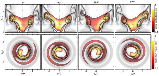
Figure 1.
Precessing vortex core (PVC) mode and flame dynamics reconstructed from time-resolved particle image velocimetry (PIV) and OH*-chemiluminescence snapshots revealing PVC-induced vortices (gray-scale) overlaid with heat release rate indicating the corresponding variation in the flame. Top row: phase-averaged heat release rate fluctuations in longitudinal section; bottom row: PVC-induced heat release rate fluctuations in cross-sectional view (x/D = 0.75). Heat release rate is normalized to maximal values.
The shown phase-averaged flow and flame dynamics were measured in a gas turbine combustor with active PVC flow control. They reveal the alternating (helical-shaped) vortices induced by the excited PVC as they propagate along the inner shear layer before they collide with the combustion chamber wall. In the cross-sectional view (bottom row in Figure 1), the helical movement in the clockwise direction induced by the PVC is depicted. The flame surface dynamics, indicated by the phase-averaged OH*-chemiluminescence fluctuations, are clearly driven by the vortex dynamics, as they entrain a very inflammable composition of fuel–air mixture and high-temperature burnt gas from the central recirculation zone. The acquisition and post-processing of the required data needed to derive this illustration are documented in some of our previous publications [26,27]. Applying different actuation amplitudes generates PVCs of different strengths which allows for investigating the impact of the PVC on important design parameters of the premixed combustion system such as thermoacoustic instabilities and pollutant emissions. Lückoff et al. [23,28] showed that an excited PVC can damp the growth rate and amplitude of thermoacoustic modes, which lead to a more stable combustion process. The loudspeaker-based flow control system was applied to show that an excited PVC slightly increases the emission level in partially and perfectly premixed flames due to increased vorticity [27].
The loudspeaker-based flow control design by Lückoff et al. is well-suited to academic purposes on a laboratory scale to study PVCs. However, robustness and applicability are lacking to implement this design as used in an industrial-scale machine. Therefore, an alternative actuator concept needs to be derived that is more robust and preferably maintenance-free. The obvious choice is fluidic oscillators, which are capable of generating an oscillating synthetic jet without moving parts [26,29].
Fluidic devices were first developed in the early 1960s at Harry Diamond Laboratories as logic elements for missile control systems [30]. These elements included oscillators [31,32], amplifiers [33], and classic logic gates [34]. With the increase in the use of electronic control systems and their increased reliability, fluidic control systems were quickly replaced. In recent years, fluidic oscillators have seen a rise in interest for addressing modern engineering problems. They are used in active flow control [35,36,37], windshield wipers [38], future combustion processes [39,40], and the generation of microbubbles in bioreactors [41,42]. However, fluidic bistable amplifiers, sometimes called fluidic switches, have not been used as much as oscillators. Bobusch and Tesař [43,44] demonstrated their use as high-speed gas valves in harsh environments. They can also be used to create high-frequency fluidic oscillators [45]. In comparison with traditional actuators, fluidic devices are virtually maintenance-free because they contain no moving parts. Additionally, they are not affected by radiation, shock, or temperature changes, and can be run from a pressure reservoir without any electronic parts. Further information on the functioning and application of fluidic oscillators may be found in the works of Gregory [46], Tesař [47,48], Foster [49], Raghu [35], and Bobusch [43].
Common feedback-type fluidic oscillators have a linear relationship between mass flow and frequency [40]. In this case, the mass flow governs the actuator’s forcing amplitude. Therefore, the independent control of actuation frequency and amplitude is impossible, but is necessary for successful control of the PVC dynamics, as achieved with the loudspeaker-based actuator [20]. Tesař [50] offered a possibility, of replacing the loudspeaker-based actuator with a more robust actuation system to facilitate the control of the PVC in industrial-scale gas turbine combustors. Following the approach of Tesař [50], the combination of a fluidic oscillator and a fluidic amplifier, which allows for the decoupling of the actuation amplitude (proportional to the mass flow) and frequency, was investigated in this study.
In the following section, the design of the newly developed fluidic actuator is described and its functionality is illustrated using numerical simulations. Subsequently, a short description of the flow control approach is provided, which includes an introduction to the concept of lock-in serving as a proof-of-concept of the actuation principle. The fourth section deals with the experimental validation and proof-of-concept of the new fluidic actuator in two different experimental setups. Finally, conclusions are drawn and an outlook for future studies are provided. This involves the presentation of a two-part stainless steel design of the successfully tested actuator for experiments under reacting flow conditions with flame.
2. Design and Functionality of the OsciAmp Fluidic Oscillator
The new actuator, named OsciAmp, was designed based on the master–slave concept. It is a two-stage layout that generates a desirable frequency in an oscillator stage, whose output switches a large mass flow downstream of an amplifier stage. In this context, the oscillator acts as a master providing frequency commands and the amplifier, as the slave, obeys and switches accordingly. Although the working principle seems simple, the practical implementation of this concept is demanding; hence, its industrial implementation has not yet been achieved, most probably because the matching of the properties between the oscillator and amplifier is a tedious task. This difficulty arises basically from the large number of inlets and outlets consisting of different conditions, i.e., pressure and flow rate, which have to be matched simultaneously [50].
Figure 2 shows the implementation of the master–slave concept used in this work. The oscillator (illustrated in red) acts as a master and the amplifier (illustrated in blue) obeys as a slave, which results in well-defined alternating synthetic jets at the two output ports. The oscillator contains an inlet and two outlets. The outlets of the oscillator are the (frequency) control ports in the amplifier. The amplifier has its own inlet and two outlets. The amplifier inlet flow is subjected to the control flows of the oscillator, which switches between the two actuator outlet ports. In this configuration, the magnitude of the mass flow through the actuator, and with the forcing amplitude, is mainly governed by the amplifier inlet flow. The forcing frequency is determined by the oscillator inlet flow. Accordingly, independent control of forcing amplitude and frequency can be achieved. The OsciAmp is a combination of the fluidic oscillator investigated in a previous study [51] with the fluidic amplifier described above. Instead of using an amplifier with a Spyropoulos-type feedback as the master (used by Tesař [50]), a sweeping-jet-type oscillator with an attached splitter geometry is used. This allows the master stage to be entirely two-dimensional and simplifies manufacturing down the line. The same sweeping oscillator was used in the aforementioned study [51], allowing the master to operate in the same frequency band without requiring several tuning iterations to match the two systems.
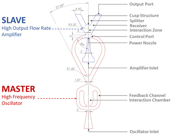
Figure 2.
Design of the actuator based on the master–slave concept. The high-frequency oscillator, as the master, provides frequency information to the high-flow output of the amplifier, which acts as a slave.
To test the functionality of the design and visualize the flow field inside the actuator, 2D-incompressible unsteady Reynolds-averaged Navier–Stokes (URANS) simulations were performed. The inlet flow rate for the oscillator and amplifier were set to 0.25 g/s and a k--SST model was selected for turbulence modeling. Figure 3 shows different phase angles of the combined system and the oscillator shows full control over the switching action of the amplifier.
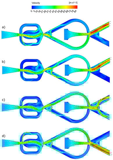
Figure 3.
Numerical results for a 2D unsteady Reynolds-averaged Navier–Stokes (URANS) simulation of the actuator’s internal flow field (a–d) from top to bottom: (a) stable condition top output; (b) the oscillator output is switching to the upper control channel, the amplifier flow is beginning to detach from the top attachment wall; (c) the oscillator flow is fully switched to the upper control channel and the amplifier flow is in the process of switching; (d) stable condition bottom output.
3. Flow Control Approach and Lock-In Investigation
In the present experimental setup, the developed fluidic oscillator was applied in an open-loop control approach. Accordingly, no feedback-signal from some sort of sensor was used to control the performance of the actuator. The amplifier and oscillator mass flows were chosen based on hot-wire measurements, which were performed to characterize the amplitude and frequency range of the actuator (Section 4.1). Under reacting conditions, the open-loop control approach was applied to excite the PVC in flow configurations where the flame dampened the PVC.
In previous publications [20,23], a lock-in study was shown to serve as a proof-of-concept for a newly developed actuator design targeting an oscillator such as the PVC. If lock-in can be achieved by the actuator system, it can be concluded that the actuator is capable of controlling the oscillator. The same strategy was followed in this study by applying open-loop control to study the lock-in behavior of the isothermal combustor flow. Terhaar et al. [52] showed that the PVC can be modeled well by a parametric nonlinear Van der Pol oscillator. The synchronization behavior of such a model oscillator with a periodic forcing is shown in the lock-in diagram in Figure 4 [53].
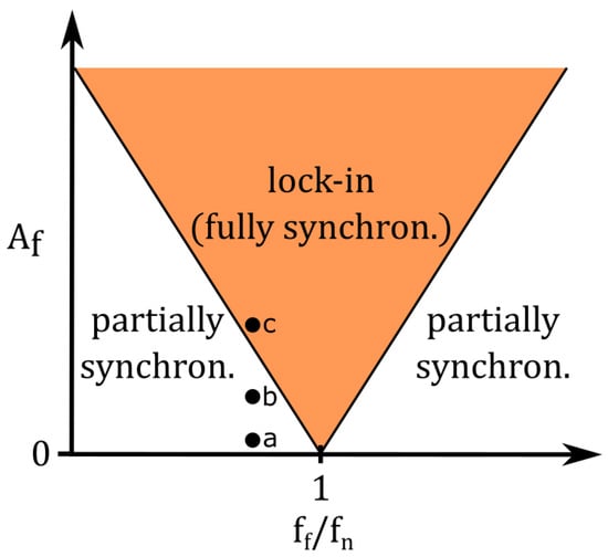
Figure 4.
Sketch of a simplified lock-in diagram describing a periodically forced model oscillator. The actuation amplitude is presented as a function of the normalized actuation frequency . Orange area: lock-in (phase and frequency fully synchronized).
This lock-in diagram typically relates the forcing amplitude to the ratio of forcing frequency and natural frequency . In the present study, the natural frequency is equal to the PVC frequency which naturally occurs in the swirling jet. The lock-in diagram describes the state of synchronization of the naturally occurring oscillator (PVC) and the forcing signal induced by the actuator. For a small value of and sufficiently far away from (point a in Figure 4), the dynamic of the (forced) oscillator will not be considerably compromised and the phases of oscillator and forcing are drifting (phase drifting). Keeping constant and increasing to moderate values leads to an effect called frequency pulling (point b in Figure 4). This effect can be observed in the power spectral density, showing that is pulled toward with increasing (compare Figure 9) [53,54]. Increasing even further and over a critical value (lock-in amplitude) causes a full synchronization of frequency () and the phases of the forcing and oscillator (point c in Figure 4). In this state, which is called lock-in, the dynamics of the oscillator are following the forcing induced by the actuator. If lock-in reaches for far from , a higher value of is required, meaning that the lock-in amplitude increases. More details on lock-in and synchronization of forced hydrodynamically self-excited jets and flames are provided in [53,54,55].
4. Experimental Validation
Firstly, this section describes the experimental validation of the functionality of the OsciAmp, which allows for independent control of frequency and amplitude. Subsequently, the flow control authority of the OsciAmp on the PVC is demonstrated inside a prototype combustor test rig.
4.1. Validation of Functionality
The functionality of the actuator was verified based on hot-wire measurements at the outlet ports of the actuator. The corresponding experimental setup for these measurements is shown in Figure 5. A single-wire probe was used, which was connected to a constant temperature anemometer to measure the velocity of the synthetic jets emanating from the actuator outlets. An oscilloscope was used to observe the instantaneous effective value of the measurement signal. The signal of the hot-wire probe was filtered and amplified with a signal conditioner and digitally processed in an A/D converter (16 bit). The digital signals were recorded and processed by a measurement computer (PC). The probe was directly aligned at the actuator outlet at a distance of approximately 15 mm. A linear translation stage was used to locate the probe at the position where the maximal magnitude of the effective velocity could be measured. This position was estimated empirically by traversing the probe around the actuator outlets. The air mass flows through the oscillator and the amplifier of the actuator were controlled by a flow controller and a rotameter, respectively. A measurement time of 30 s was taken with a sampling frequency of Hz to obtain a quasi-stationary statistical moment of the fluctuating velocities.
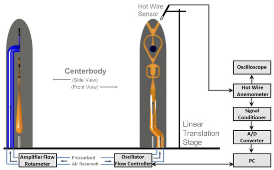
Figure 5.
Hot-wire measurement setup for the measurement of the velocity of the flow at the outlet of the actuator.
In the first experiment, the operational range of the actuator was estimated by varying the amplifier and oscillator mass flows. Based on the measured velocity signals, the power spectral density (PSD) spectra were generated, which served to characterize the oscillation characteristics of the actuator for different combinations of amplifier and oscillator mass flows. An amplifier mass flow range between approximately 0.775 and 2.327 kg/h, an oscillator mass flow range between approximately 0.4 and 0.8 kg/h, and a frequency range between approximately 100 and 190 Hz were determined based on this preliminary evaluation.
In a subsequent experiment, the total mass flow (sum of oscillator and actuator mass flows) through the actuator was kept constant to generate a constant actuation amplitude with varying frequency. Starting at a total mass flow of kg/h, the following steps were carried out:
- The total mass flow was kept constant at kg/h. The oscillator flow was set to the minimum and the amplifier flow was adjusted accordingly to maintain constant total mass flow.
- For the same total mass flow, the oscillator flow was gradually increased in equivalent to 10 Hz steps and the amplifier flow was adjusted accordingly to maintain a constant total mass flow.Goal: Demonstrate the possibility of changing frequency without changing the actuation amplitude.
- The total mass flow was increased by kg/h and step 2 was repeated.Goal: Demonstrate the possibility of changing frequency for a higher (constant) actuation amplitude.
- Step 3 was repeated until maximum total mass flow in the estimated range was achieved.Goal: Demonstrate applicability of the actuation concept over the entire operational range of the actuator.
Figure 6 summarizes the results of this experiment following the four steps described above. The root mean square (RMS) velocity as a measure of the amplitude of the actuator is plotted against the frequency of the oscillation. The figure demonstrates the possibility of changing the frequency for the same constant amplitude within the operational range of the actuator. The figure shows the actuation amplitude can be varied for a constant frequency. These variations only require a change in the mass flow through the oscillator to adjust the frequency or a change in the amplifier mass flow to vary the actuation amplitude. Additionally, the figure depicts the operational range of the fluidic actuator developed in this study. Finally, Figure 7 shows that the measured RMS velocities are linearly related to the supplied total mass flow. This linear relation holds for the whole actuation frequency range, which underlines OsciAmp’s versatility and applicability as an actuator for targeted control of the PVC’s dynamics.
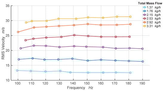
Figure 6.
Independent control of frequency and amplitude. The diagram shows the root mean square (RMS) values of the velocity signals at the outlet ports for different actuation frequencies. It demarcates the operational range of the fluidic actuator.
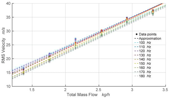
Figure 7.
Linear fit between RMS velocity and total mass flow. The approximation was achieved by fitting the linear function to the measured data points.
4.2. Validation of Flow Control Authority
After the validation of OsciAmp’s functionality, this actuator was built into a prototype combustion chamber test rig where a PVC was generated in an isothermal swirling flow without flame. In this setup, the flow control authority of OsciAmp was studied based on a lock-in study. This section starts with a description of the experimental setup, the post-processing of the recorded pressure signals, and the measurement procedure. In the following results section, the capability of the actuator to achieve lock-in is discussed.
4.2.1. Experimental Setup
The experimental setup for the validation of the flow control authority is sketched in Figure 8. A section through the generic swirl-stabilized combustor test rig is presented on the left side. The main air flow enters the test rig at the bottom and propagates through a swirler (shown in green), which transforms the non-swirling turbulent flow into swirling flow. The swirl generator consists of movable blocks, with which swirl numbers between 0 and 1.5 can be set. In this work, a constant swirl number of was used. The swirling flow propagates through the mixing tube and around a centerbody before it enters the quartz glass combustion chamber. The fluidic actuator is integrated in this centerbody. The mixing tube and front plate are composed of plastic and contain various pressure measurement ports. Further details about this test rig and the pressure measurement system are provided in [20]. The present prototype test rig only allows for isothermal experiments without flame.
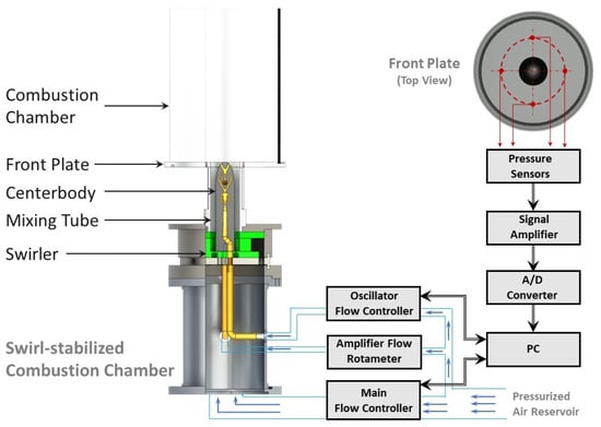
Figure 8.
Measurement setup for validation of the flow control authority: prototype combustor test rig on the left and pressure measurement chain on the right.
The actuator inside the centerbody is supplied with air via a separate pressurized air line. The incoming air is divided into two lines and connected to a rotameter and a flow controller, which in turn are connected to the amplifier and oscillator, respectively. The amplifier and oscillator are supplied with air flows at 2.5 and 3.5 bar of air, respectively. The pressure is measured far upstream of the actuator, which explains the relatively high pressure values required to compensate for the pressure loss in the flow controller, rotameter, and the connecting channels. Accordingly, the pressures inside oscillator and amplifier are considerably lower, allowing for stable and sub-critical flow conditions inside the actuator.
The experimental setup allows for measuring the differential pressure at the front plate and inside the mixing tube. For that, differential pressure sensors can be integrated at the front plate and the walls of the mixing tube. The red points on the top right view of the front plate, as shown in Figure 8, represent the locations at which the pressure is measured. The four pressure sensors are arranged circumferentially around the burner outlet. The sensors have a measuring range of 1000 Pa and allow for measuring pressure fluctuations up to 0.1 Pa. The analog signals of the sensors are amplified and digitally converted with a sample frequency of 8192 Hz.
4.2.2. Post-Processing of the Pressure Signals
The pressure signals measured from four circumferentially arranged sensors were decomposed into Fourier modes. The spatial Fourier mode decomposition in azimuthal direction for the mth azimuthal mode is defined as
where represents the pressure signal of the kth sensor and m represents the azimuthal wavenumber. With the four equidistantly placed and circumferentially arranged sensors, azimuthal modes of can be determined. The estimated Fourier coefficient is a function of time and complex. For an azimuthal number of unity , the Fourier mode represents the PVC in its instantaneous amplitude and phase. These coefficients were used to calculate the power spectral density, which is visualized in the frequency spectra shown in Figure 9.
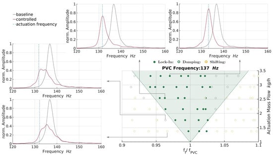
Figure 9.
Validation of flow control authority. Lock-in diagram (bottom right) and surrounding example of spectra show lock-in, damping, and shifting response of the PVC to the actuation.
4.2.3. Measurement Procedure
For the case presented in this study, the PVC was actuated with different frequencies ranging around the natural PVC frequency Hz. The differential pressure signal was measured for 40 s with a sampling rate of 8192 samples/s. The aim of the pressure measurements was to determine the dynamic behavior of the PVC for different forcing frequencies () and amplitudes.
At first, the dynamic pressure was measured in the natural flow where no external forcing was applied by the actuator. The corresponding natural PVC dynamics were characterized by the frequency peak at , as shown in the spectra in Figure 9 (grey solid line). Before the natural flow was forced by the actuator, the adjusted actuation (amplifier and oscillator flow) was characterized by an individual pressure measurement without main flow. The resulting forcing frequency was derived from the peak frequency in the PSD spectrum of the corresponding pressure signal (blue dotted line in Figure 9). Finally, the impact of the forcing, applied by the actuator, on the natural PVC was estimated based on pressure measurements where main flow and forcing were active. The resulting spectra are illustrated by the red solid lines in Figure 9.
4.2.4. Results
The impact of the forcing, induced by the fluidic actuator, on the natural PVC can be differentiated into three categories, which are related to those explained in connection with the simplified lock-in diagram shown in Figure 4. Category one involves all the combinations of forcing amplitudes and frequencies where lock-in occurs, which means that the PVC is fully synchronized with the forcing. In a PSD spectrum, the lock-in state is characterized by a single distinct peak at the forcing frequency (compare the spectra in the top row of Figure 9). Another category, which is referred to as damping, includes all cases without a distinct frequency peak in the corresponding spectrum. In these cases, the forcing is not strong enough to generate lock-in, such that the PVC is not oscillating at a distinct frequency, but temporarily escapes from the induced forcing. As a result, a very broad peak evolves in the PSD spectrum, covering primarily frequencies between forcing and natural frequency (compare the top spectrum on the left of Figure 9). At even smaller forcing amplitudes, the forcing shifts the frequency peak slightly toward the forcing frequency due to the frequency-pulling effect described above. In the present study, this shifting was accompanied by a reduction in the PVC amplitude and a broadening in the frequency peak.
To classify the individual measurements into the three categories described above, certain threshold values and criteria need to be defined, which was achieved in this study as follows:

- Lock-In: &

- Damping: &

- Shifting:.
In these criteria, the variables f and A represent the frequency and the amplitude, respectively; the subscripts , f and represent the natural PVC signal (main flow without forcing), the forcing signal (forcing without main flow), and the interaction of forcing and natural PVC (main flow with forcing), respectively. The mentioned margins are reasonable considering the associated systematic and averaging errors.
With these criteria, the impact of the forcing on the natural PVC was characterized for different combinations of forcing frequency and amplitude, as presented in the lock-in diagram in Figure 9. The ordinate shows the total actuation mass flow, representing the amplitude of the forcing, and the abscissa shows the normalized forcing frequency relative to the natural PVC frequency. The green full circles in the diagram represent cases where lock-in occurred and the hollow green circles represent the damping cases. A V-form distribution containing the lock-in and damping cases is demarcated in light green (Figure 9) and agrees very well with the orange region in the lock-in diagram shown in Figure 4. The hollow yellow circles represent the shifting cases of the natural PVC frequency toward the forcing frequency.
The exemplary spectra arranged around the lock-in diagram illustrate the changes in the PVC dynamics due to forcing with constant frequency and increasing amplitude, which was induced by the newly designed fluidic oscillator, named OsciAmp. The impact of this forcing on the PVC is similar to the effect of the actuation induced by the loudspeaker-based actuator used in [20]. A small forcing amplitude broadens the characteristic spectral peak, which decreases the amplitude in connection with a small shift toward the forcing frequency (compare the bottom plot in the left column in Figure 9). By increasing the amplitude slightly, the peak is pulled closer toward the forcing frequency, whereas the amplitude remains low (compare the top plot in the left column in Figure 9). In this state, the PVC frequency considerably alternates between the forced and the natural PVC frequency. This dynamic changes distinctly when the actuation increases into the light green lock-in area. For those combinations of forcing frequency and amplitude situated inside this area, the corresponding spectra (see the top row in Figure 9) show a very distinct peak at the forcing frequency. Increasing the actuation amplitude further increases the amplitude of the forced PVC. The V-form of the lock-in diagram is in line with that in other studies [20,55].
In summary, the lock-in diagram in connection with the spectra shown in Figure 9 demonstrates that the newly designed fluidic actuator is capable of controlling the PVC in an open-loop control approach. The spectra show that the amplitude of the PVC can be damped considerably for low forcing amplitudes. For high amplitudes, the PVC synchronizes with the forcing, which confirms the full control authority of the actuator.
5. Conclusions and Outlook
In this work, a new fluidic actuator design, named OsciAmp, for active flow control of the PVC in a swirl-stabilized combustor was presented and analyzed regarding its functionality and control authority. We showed that the combination of oscillator and amplifier allows for independently adjusting the forcing amplitude and frequency. This feature tremendously extends the range of application for active flow control purposes compared with an actuator consisting of only a single fluidic oscillator. Therefore, the OsciAmp actuator was predestined to control a large-scale coherent flow structure as the PVC frequency grows linearly with the main flow rate. Based on a lock-in study, we found that the OsciAmp is capable of synchronizing the natural PVC with the induced forcing. The findings prove the flow control authority of the actuator and serve as a general proof of concept. In the state of lock-in, distinct PVC dynamics are achieved, which allows for detuning resonating technical systems, such as hydro turbines or gas turbine combustors. These damping and detuning capabilities are valuable control properties that can help to stabilize turbomachines affected by hydrodynamic instabilities such as the PVC.
As shown in previous studies, the PVC has the potential to considerably damp thermoacoustic instabilities in premixed swirl-stabilized combustion systems. Open-loop flow control, as conducted in this work, can lead to a damping of thermoacoustic instabilities, which increases the stability and efficiency of the combustion system. In addition to swirl-stabilized combustion chambers, other turbomachines such as hydro turbines have to deal with helical flow instabilities similar to the PVC described in this study. Accordingly, the fluidic actuator developed in this work may serve to improve the performance of different types of turbomachines.
To include the new fluidic actuator design into a combustion chamber where a swirl-stabilized flame is present, the manufacturing method and material properties need to be modified to withstand high temperatures. Therefore, stainless steel was chosen as the material, which is processed applying computerized numerical control (CNC) milling technologies. The modified two-part design, containing the same oscillator and amplifier geometries of the design discussed above, is shown in Figure 10. Both halves are aligned with two center pins and assembled with four screws. The centerbody is finally sealed with a circumferential weld seam. This stainless steel centerbody can replace the one used in the loudspeaker-based actuator, which was applied in previous studies examining the active flow control of the PVC [20,21,22,23]. This robust and versatile design of a maintenance-free actuator appears to be much more applicable to industrial-scale applications and may pave the way to active PVC control in turbomachinery.
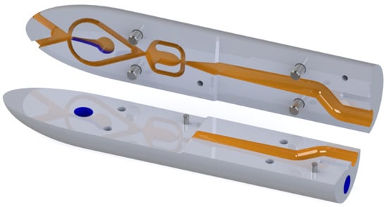
Figure 10.
Two-part design stainless steel actuator for application in a combustion chamber.
Author Contributions
Conceptualization, K.O. and F.L.; software, T.S. and A.A.; validation, A.A., F.L., and T.S.; investigation, A.A. and F.L.; data curation, A.A. and F.L.; writing—original draft preparation, A.A., F.L., and T.S.; writing—review and editing, K.O., F.L., A.A., and T.S.; visualization, A.A., T.S. and F.L.; supervision, K.O.; project administration, F.L.; funding acquisition, K.O. All authors have read and agreed to the published version of the manuscript.
Funding
German Reserach Foundation (DFG), grant number 247226395.
Data Availability Statement
The data presented in this study are available on request from the corresponding author.
Acknowledgments
We would like to thank the German Research Foundation (DFG) for funding this work within the project 247226395. Special thanks go out to Andy Göhrs for his technical support as well as Sara Schulz and Daniel Barkowski, who dedicated their Bachelor and Master thesis to the development of the actuator studied in this paper.
Conflicts of Interest
The authors declare no conflict of interest.
Abbreviations
The following abbreviations are used in this manuscript:
| CNC | Computerized Numerical Control |
| PSD | Power Spectral Density |
| PVC | Precessing Vortex Core |
| RMS | Root mean square |
| URANS | Unsteady Reynolds-averaged Navier–Stokes |
References
- Syred, N.; Beer, J.M. Combustion in Swirling Flows: A Review. Combust. Flame 1974, 23, 143–201. [Google Scholar] [CrossRef]
- Beér, J.; Chigier, N. Combustion Aerodynamics; Fuel and Energy Science Series; Applied Science Publishers Limited: Barking, UK, 1972. [Google Scholar]
- Liang, H.; Maxworthy, T. An experimental investigation of swirling jets. J. Fluid Mech. 2005, 525, 115–159. [Google Scholar] [CrossRef]
- Oberleithner, K.; Paschereit, C.O.; Seele, R.; Wygnanski, I. Formation of Turbulent Vortex Breakdown: Intermittency, Criticality, and Global Instability. AIAA J. 2012, 50, 1437–1452. [Google Scholar] [CrossRef]
- Terhaar, S.; Reichel, T.G.; Schrödinger, C.; Rukes, L.; Paschereit, C.O.; Oberleithner, K. Vortex Breakdown Types and Global Modes in Swirling Combustor Flows with Axial Injection. J. Propuls. Power 2015, 31, 219–229. [Google Scholar] [CrossRef]
- Petz, C.; Hege, H.C.; Oberleithner, K.; Sieber, M.; Nayeri, C.N.; Paschereit, C.O.; Wygnanski, I.; Noack, B.R. Global modes in a swirling jet undergoing vortex breakdown. Phys. Fluids 2011, 23, 091102. [Google Scholar] [CrossRef]
- Oberleithner, K.; Sieber, M.; Nayeri, C.N.; Paschereit, C.O.; Petz, C.; Hege, H.C.; Noack, B.R.; Wygnanski, I. Three-dimensional coherent structures in a swirling jet undergoing vortex breakdown: Stability analysis and empirical mode construction. J. Fluid Mech. 2011, 679, 383–414. [Google Scholar] [CrossRef]
- Oberleithner, K.; Terhaar, S.; Rukes, L.; Paschereit, C.O. Why Nonuniform Density Suppresses the Precessing Vortex Core. J. Eng. Gas Turb. Power 2013, 135, 121506. [Google Scholar] [CrossRef]
- Terhaar, S.; Oberleithner, K.; Paschereit, C. Key parameters governing the precessing vortex core in reacting flows: An experimental and analytical study. Proc. Combust. Inst. 2015, 35, 3347–3354. [Google Scholar] [CrossRef]
- Syred, N. A review of oscillation mechanisms and the role of the precessing vortex core (PVC) in swirl combustion systems. Prog. Energy Combust. Sci. 2006, 32, 93–161. [Google Scholar] [CrossRef]
- Stöhr, M.; Sadanandan, R.; Meier, W. Experimental study of unsteady flame structures of an oscillating swirl flame in a gas turbine model combustor. Proc. Combust. Inst. 2009, 32, 2925–2932. [Google Scholar] [CrossRef]
- Galley, D.; Ducruix, S.; Lacas, F.; Veynante, D. Mixing and stabilization study of a partially premixed swirling flame using laser induced fluorescence. Combust. Flame 2011, 158, 155–171. [Google Scholar] [CrossRef]
- Stöhr, M.; Boxx, I.; Carter, C.D.; Meier, W. Experimental study of vortex flame interaction in a gas turbine model combustor. Combust. Flame 2012, 159, 2636–2649. [Google Scholar] [CrossRef]
- Candel, S.; Durox, D.; Schuller, T.; Bourgouin, J.F.; Moeck, J.P. Dynamics of Swirling Flames. Annu. Rev. Fluid Mech. 2014, 46, 147–173. [Google Scholar] [CrossRef]
- Stöhr, M.; Arndt, C.; Meier, W. Transient effects of fuel-air mixing in a partially-premixed turbulent swirl flame. Proc. Combust. Inst. 2015, 35, 3327–3335. [Google Scholar] [CrossRef]
- Stöhr, M.; Oberleithner, K.; Sieber, M.; Yin, Z.; Meier, W. Experimental Study of Transient Mechanisms of Bi-Stable Flame Shape Transitions in a Swirl Combustor. In Proceedings of the Turbo Expo 2017: Turbomachinery Technical Conference and Exposition, Charlotte, NC, USA, 26–30 June 2017. [Google Scholar]
- Mathews, B.; Hansford, S.; O’Connor, J. Impact of Swirling Flow Structure on Shear Layer Vorticity Fluctuation Mechanisms. In Proceedings of the ASME Turbo Expo 2016: Turbomachinery Technical Conference and Exposition, Seoul, Korea, 13–17 June 2016. [Google Scholar]
- Frederick, M.; Manoharan, K.; Dudash, J.; Brubaker, B.; Hemchandra, S.; O’Connor, J. Impact of Precessing Vortex Core Dynamics on Shear Layer Response in a Swirling Jet. J. Eng. Gas Turbines Power 2018, 140, 061503. [Google Scholar] [CrossRef]
- Paschereit, C.O.; Gutmark, E.J. Combustion instability and emission control by pulsating fuel injection. J. Turbomach. 2008, 130, 011012. [Google Scholar] [CrossRef]
- Lückoff, F.; Sieber, M.; Paschereit, C.O.; Oberleithner, K. Characterization of Different Actuator Designs for the Control of the Precessing Vortex Core in a Swirl-Stabilized Combustor. J. Eng. Gas Turbines Power 2017, 140, 041503. [Google Scholar] [CrossRef]
- Lückoff, F.; Sieber, M.; Oberleithner, K. Open-Loop Control of the Precessing Vortex Core in a Swirl-stabilized Combustor: Impact on Flame Shape and Flame Stability. In Proceedings of the ASME Turbo Expo 2018: Turbomachinery Technical Conference and Exposition, Oslo, Norway, 11–15 June 2018. [Google Scholar]
- Lückoff, F.; Sieber, M.; Paschereit, C.O.; Oberleithner, K. Phase-Opposition Control of the Precessing Vortex Core in Turbulent Swirl Flames for Investigation of Mixing and Flame Stability. J. Eng. Gas Turbines Power 2019, 141, 111008. [Google Scholar] [CrossRef]
- Lückoff, F.; Oberleithner, K. Excitation of the precessing vortex core by active flow control to suppress thermoacoustic instabilities in swirl flames. Int. J. Spray Combust. Dyn. 2019, 11, 1756827719856237. [Google Scholar] [CrossRef]
- Cattafesta, L.N., III; Sheplak, M. Actuators for Active Flow Control. Annu. Rev. Fluid Mech. 2011, 43, 247–272. [Google Scholar] [CrossRef]
- Kuhn, P.; Moeck, J.P.; Paschereit, C.O.; Oberleithner, K. Control of the Precessing Vortex Core by Open and Closed-Loop Forcing in the Jet Core. In Proceedings of the ASME Turbo Expo 2016: Turbomachinery Technical Conference ans Exposition, Seoul, Korea, 13–17 June 2016. [Google Scholar]
- Sieber, M.; Ostermann, F.; Woszidlo, R.; Oberleithner, K.; Paschereit, C. Oliver. Lagrangian coherent structures in the flow field of a fluidic oscillator. Phys. Rev. Fluids 2016, 1, 050509. [Google Scholar] [CrossRef]
- Lückoff, F.; Sieber, M.; Paschereit, C.O.; Oberleithner, K. Impact of the Precessing Vortex Core on NOx Emissions in Premixed Swirl-Stabilized Flames–An Experimental Study. J. Eng. Gas Turbines Power 2020, 142, 111010. [Google Scholar] [CrossRef]
- Lückoff, F.; Kaiser, T.L.; Paschereit, C.O.; Oberleithner, K. Mean field coupling mechanisms explaining the impact of the precessing vortex core on the flame transfer function. Combust. Flame 2021, 223, 254–266. [Google Scholar] [CrossRef]
- Woszidlo, R.; Ostermann, F.; Nayeri, C.N.; Paschereit, C.O. The time-resolved natural flow field of a fluidic oscillator. Exp. Fluids 2015, 56. [Google Scholar] [CrossRef]
- Campagnuolo, C.J.; Lee, H.C. Review of Some Fluid Oscillators; Section: Technical Reports; Harry Diamond Labs: Adelphi, MD, USA, 1969. [Google Scholar]
- Spyropoulos, C.E. A sonic oscillator(Operational principles and characteristics of sonic oscillator- pneumatic clock pulse generator). In Proceedings of the Fluid Amplification Symposium, Washington, DC, USA, 26–28 May 1964; Volume 3, pp. 27–52. [Google Scholar]
- Warren, R.W. Fluid Oscillator. U.S. Patent US3016066A, 9 January 1962. [Google Scholar]
- Warren, R. Some parameters affecting the design of bistable fluid amplifiers. In ASME Symposium of Fluid Jet Control Devices; ASME: New York, NY, USA, 1962; pp. 75–82. [Google Scholar]
- O’keefe, R.F. Fluidic Elements and Devices Thereof. U.S. Patent US3495608A, 17 February 1970. [Google Scholar]
- Raghu, S. Fluidic oscillators for flow control. Exp. Fluids 2013, 54, 1455. [Google Scholar] [CrossRef]
- Woszidlo, R.; Wygnanski, I. Parameters governing separation control with sweeping jet actuators. In Proceedings of the 29th AIAA Applied Aerodynamics Conference, Honolulu, HI, USA, 27–30 June 2011; p. 3172. [Google Scholar]
- Cerretelli, C.; Gharaibah, E. An Experimental and Numerical Investigation on Fluidic Oscillators for Flow Control. In Proceedings of the 37th AIAA Fluid Dynamics Conference and Exhibit, Miami, FL, USA, 25–28 June 2007. [Google Scholar]
- Stouffer, R.D. Fluidic Washer Systems for Vehicles. U.S. Patent US5749525A, 12 May 1998. [Google Scholar]
- Guyot, D.; Bobusch, B.; Paschereit, C.O.; Raghu, S. Active Combustion Control Using a Fluidic Oscillator for Asymmetric Fuel Flow Modulation. In Proceedings of the 44th AIAA/ASME/SAE/ASEE Joint Propulsion Conference & Exhibit, Hartford, CT, USA, 21–28 July 2008. [Google Scholar]
- Bobusch, B.C.; Woszidlo, R.; Bergada, J.; Nayeri, C.N.; Paschereit, C.O. Experimental study of the internal flow structures inside a fluidic oscillator. Exp. Fluids 2013, 54, 1559. [Google Scholar] [CrossRef]
- Tesař, V. Microbubble generation by fluidics. Part I: Development of the oscillator. In Proceedings of the Colloquium Fluid Dynamics, Rome, Italy, 9–13 September 2012. [Google Scholar]
- Gilmour, D.; Zimmerman, W. Microbubble intensification of bioprocessing. Adv. Microb. Physiol. Vol. 2020, 77, 1. [Google Scholar]
- Bobusch, B.C. Fluidic Devices for Realizing the Shockless Explosion Combustion Process. Ph.D. Thesis, Technische Universität Berlin, Fakultät V- Verkehrs- und Maschinensysteme, Berlin, Germany, 2015. [Google Scholar]
- Tesař, V. Fluidic Valves for Variable-Configuration Gas Treatment. Chem. Eng. Res. Des. 2005, 83, 1111–1121. [Google Scholar] [CrossRef][Green Version]
- Tesař, V.; Zhong, S.; Rasheed, F. New Fluidic-Oscillator Concept for Flow-Separation Control. AIAA J. 2013, 51, 397–405. [Google Scholar] [CrossRef]
- Gregory, J.; Tomac, M.N. A Review of Fluidic Oscillator Development and Application for Flow Control. In Proceedings of the 43rd AIAA Fluid Dynamics Conference, San Diego, CA, USA, 24–27 June 2013. [Google Scholar]
- Tesař, V. Pressure-Driven Microfluidics; Artech House Publishers: Norwood, UK, 2007. [Google Scholar]
- Tesař, V. Taxonomic trees of fluidic oscillators. In EPJ Web of Conferences; EDP Sciences: Paris, France, 2017; Volume 143, p. 02128. [Google Scholar]
- Foster, K.; Parker, G.A. Fluidics: Components and Circuits; John Wiley & Sons: New York, NY, USA, 1970. [Google Scholar]
- Tesař, V. “Master and Slave” fluidic amplifier cascade. In EPJ Web of Conferences; EDP Sciences: Paris, France, 2015; Volume 25, p. 01093. [Google Scholar]
- Barkowski, D. Open-Loop Kontrolle des präzidierenden Wirbelkerns (PVC) einer isothermen Drallströmung in Einer Modellbrennkammer mit Einem Fluidischen Oszillator. Master’s Thesis, TU Berlin, Berlin, Germany, 2019. [Google Scholar]
- Terhaar, S.; Ćosić, B.; Paschereit, C.; Oberleithner, K. Suppression and excitation of the precessing vortex core by acoustic velocity fluctuations: An experimental and analytical study. Combust. Flame 2016, 172, 234–251. [Google Scholar] [CrossRef]
- Li, K.B.; Juniper, M.P. Phase trapping and slipping in a forced hydrodynamically self-excited jet. J. Fluid Mech. 2013, 735. [Google Scholar] [CrossRef]
- Li, K.B.; Juniper, M.P. Lock-in and quasiperiodicity in hydrodynamically self-excited flames: Experiments and modelling. Proc. Combust. Inst. 2013, 34, 947–954. [Google Scholar] [CrossRef]
- Li, K.B.; Juniper, M.P. Lock-in and quasiperiodicity in a forced hydrodynamically self-excited jet. J. Fluid Mech. 2013, 726, 624–655. [Google Scholar] [CrossRef]


Publisher’s Note: MDPI stays neutral with regard to jurisdictional claims in published maps and institutional affiliations. |
© 2021 by the authors. Licensee MDPI, Basel, Switzerland. This article is an open access article distributed under the terms and conditions of the Creative Commons Attribution (CC BY) license (http://creativecommons.org/licenses/by/4.0/).