Article

Free Flow and Discharge Characteristics of Trapezoidal-Shaped Weirs

by
Yebegaeshet T. Zerihun
David & James—Engineering and Environmental Consultancy, 204 Albion Road, Victoria 3350, Australia
Fluids 2020, 5(4), 238; https://doi.org/10.3390/fluids5040238
Submission received: 1 November 2020 / Revised: 29 November 2020 / Accepted: 30 November 2020 / Published: 10 December 2020
(This article belongs to the Special Issue Modelling the Behaviour of Water Systems to Increase Sustainability)

Abstract

:
A number of studies have considered the effects of weir design variations on the free- and submerged-flow characteristics of trapezoidal broad-crested weirs. It appears that the hydraulics of short-crested weir flows have received little attention; thus, the current knowledge is incomplete. By systematically analyzing a large set of experimental data, the present study aims to fill in this knowledge gap and to provide a complete description of the discharge characteristics of trapezoidal-shaped weirs, including the salient features of two-dimensional weir flows. The analysis of the axial free-surface profiles for short-crested weir flows attested that the location of the nearest station for the correct measurement of the overflow depth under free-flow conditions is at η 0 from the heel of the weir, where η 0 is the upstream free-surface elevation. Additionally, an empirical equation for the free-flow discharge coefficient is proposed as being valid for a trapezoidal-shaped weir with varying upstream- and downstream-face slopes. The results of this investigation reveal that the streamline curvature and the slopes of the upstream and downstream weir faces significantly affect the streamwise flow patterns and, hence, the free-flow discharge.

1. Introduction

Theoretical and experimental investigations of free-surface flows over trapezoidal-shaped weirs have numerous applications, especially in the analyses of flood flows over common types of civil infrastructures such as highway embankments and coastal levees. The outcomes of these analyses may be utilized to develop a design guideline and a reliable flood risk management strategy. Nowadays, work is ongoing to study the hydraulic characteristics of flows over these weirs under free- and submerged-flow conditions, aiming to accurately determine their discharge capacity by considering the variations of the weir design. Trapezoidal-shaped weirs are generally classified into two groups, namely broad-crested and short-crested weirs, depending on the ratio of the upstream crest-referenced energy head, H 0 , to the crest length in a streamwise direction, L . For a broad-crested weir ( 0.07 ζ = H 0 / L 0.50 , ζ is the relative overflow head), the flow over the weir crest is nearly uniform with a hydrostatic pressure distribution [1]. In contrast, the curvilinear transcritical flow over a short-crested weir is characterized by substantial streamline curvatures, as depicted in Figure 1. For accurate description of its discharge characteristics, the equation of the free-flow discharge coefficient must include terms that account for the effects of non-hydrostatic pressure distribution (see, e.g., [1,2]). As pointed out by Zerihun and Fenton [3], only a curved transcritical flow over a weir can be considered essentially as a fully non-hydrostatic free-surface flow. The hydraulics of such a flow will be the primary issue of this experimental-based investigation.
Flows over trapezoidal-shaped weirs have been extensively studied experimentally. A pioneering experimental study on their hydraulic characteristics was carried out by Bazin [4]. He performed the tests in a smooth concrete canal 215 m long and 2 m wide. Some of the tests encompassed weirs 500 and 750 mm high, with vertical or sloping upstream and downstream faces. The results clearly reveal the effects of nappe shapes on the head-discharge characteristics. Sigurdsson [5] conducted an experimental study on the flow over a broad-crested type of an embankment-shaped weir. The study was mainly concerned with the assessment of the influence of the boundary layer on the free-flow discharge characteristics. Using compiled experimental data, Kindsvater [6] further investigated the flow characteristics of embankment-shaped weirs under free- and submerged-flow conditions. For analyzing the discharge of submerged weirs, Skogerboe et al. [7] presented a simple method based on the momentum principle. Compared to other methods (e.g., [6,8,9,10]), their method directly yields the submerged-flow discharge of a broad-crested weir. Pinto and Ota [11] studied the pressure distribution on the downstream face of a submerged dike. They investigated the effects of the variation of the tailwater depth on the bed-pressure distribution; however, the results were not generalized. Fritz and Hager [12] conducted a detailed experimental investigation to examine the characteristics of the flow downstream of submerged trapezoidal-shaped weirs. They considered weirs with upstream- and downstream-face slopes of 26.57° and crest lengths varying from 0 to 300 mm. For this particular weir geometry, an empirical equation for the free-flow discharge coefficient was developed. However, the effect of the variation of the upstream- and downstream-face slopes on weir flow has not been considered. Zerihun [2] also carried out experiments on flows over trapezoidal-shaped weirs with upstream and downstream faces sloped at 26.57°. Weirs of different crest lengths but constant height ( w = 150 mm) were used for the tests. Measurements of free-surface and bed-pressure profiles and velocity distributions were taken to examine the features of the short-crested weir flows under free- and submerged-flow conditions. Sargison and Percy [13] studied transcritical flows over broad-crested weirs with varying upstream- and downstream-face slopes. For such flows, they considered the effect of the upstream-face slope to extend the discharge coefficient equation of Fritz and Hager [12]. Following a similar approach, Salmasi and Abraham [14] recently investigated the effects of the upstream-face slope on the hydraulic performance of ogee weirs. Azimi et al. [15] also conducted a systematic investigation on the discharge characteristics of trapezoidal-shaped weirs. For a broad-crested type of these weirs, the effect of surface roughness on the discharge characteristics was examined by Felder and Islam [16] and Pařílková et al. [17]. Using dimensional analysis and incomplete self-similarity theory, Di Stefano et al. [18] generalized the stage–discharge relationship for broad-crested weirs with various geometric shapes.
Additionally, several numerical investigations were carried out to assess the hydraulic characteristics of weir flows under free-flow conditions. Hargreaves et al. [19] studied the two-dimensional (2D) structure of free flow over a rectangular broad-crested weir using the Fluent software package. Soydan-Oksal et al. [20] performed a similar study to examine the salient features of the flow over a trapezoidal broad-crested weir. They employed computational models based on the Reynolds-averaged Navier–Stokes equations in two- and three-dimensional settings. The numerical results of both studies were verified with the experimental data. Using a Boussinesq-type model, Zerihun and Fenton [3] analyzed the mean flow characteristics of free-surface flows over trapezoidal-shaped weirs and obtained results that are compatible with the experimental data. The characteristics of broad-crested weir flow, including the effects of the upstream weir face slope, were investigated by Xu and Jin [21]. Fathi-Moghaddam et al. [22] numerically studied transcritical flow over a broad-crested type of trapezoidal gabion weirs. They considered weirs with various upstream- and downstream-face slopes and examined the hydraulic efficiency of these weirs.
Most of the abovementioned studies accounted for the effects of weir design variations on the free- and submerged-flow characteristics of trapezoidal broad-crested weirs. It appears that the hydraulics of free-surface flows over a short-crested type of these weirs have not received sufficient attention; thus, the current knowledge is incomplete. The present study aims at filling this knowledge gap and providing a complete description of the discharge characteristics of trapezoidal-shaped weirs, including the salient features of the 2D weir flows. The results of previous investigations on flow over various weir shapes show that the weir geometry, especially the upstream and downstream weir face slopes, significantly affects the free-flow discharge coefficient (see, e.g., [23,24,25,26,27]). As is generally known, a variation in the downstream-face slope leads to a change in the degree of the streamline curvature over the weir crest and hence, a modification of the discharge coefficient. Similarly, the upstream-face slope affects the free-flow discharge coefficient, influencing the streamline pattern of the approach flow and the development of the flow separation zone. Thus, the equation for the free-flow discharge coefficient will be developed by accounting for the effects of the streamline curvature and slopes of the upstream and downstream weir faces. Such a general-purpose equation can provide a practical solution to the problem of the discharge capacity of a broad-crested or a short-crested type of trapezoidal-shaped weir.
The remaining sections of the paper are organized as follows: firstly, a brief discussion on the nature of the free-surface profile of a short-crested weir flow is presented. Then, the non-hydrostatic pressure distribution is examined, and the results are briefly described. In Section 4, the proposed equation for the free-flow discharge coefficient is calibrated and validated using available experimental data. Finally, the paper ends with conclusions.

2. Method

A large set of experimental data [2,4,12,13] for the local flow characteristics and free-flow discharge of a trapezoidal-shaped weir was systematically synthesized; the results are presented in the following section. In order to provide detailed insight into the 2D characteristics of the short-crested weir flow, the analysis of free-surface and bed-pressure profiles is first presented. Table 1 summarizes the experimental studies with the ranges of the various parameters. The approach Froude number, F 0 , is based on the flow parameters at the upstream end section and is relatively low. The presence of size-scale effects can affect the physical processes of the flow, thus making the prediction of the behavior of a prototype flow using laboratory data more difficult. In this study, the effects of viscosity and surface tension on the experimental data were examined based on the general criteria recommended by Curtis [28] and Hager [24]. Accordingly, measurements with overflow depths less than 50 mm were excluded from the analysis. In addition, the flow data of weirs with a minimum structural height of 150 mm were considered, thereby reducing high measurement uncertainties.

3. Data Analysis and Results

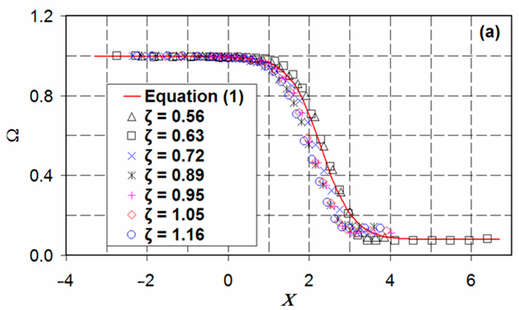
3.1. Free-Surface Profiles

The normalized free-surface profile for short-crested weir flows with different values of relative overflow head ( 0.50 < ζ < 1.20 ) is shown in Figure 2a. In this figure, the normalized free-surface elevation Ω ( = η / η 0 ) is plotted versus the non-dimensional horizontal distance Χ ( = x / η 0 ) , where η is the free-surface elevation above the x -axis datum (see Figure 1a), and η 0 is the elevation of the free surface at the gaging station. The test data were taken from the experiments conducted by Zerihun [2]. The variation of the normalized free-surface elevation can be described by a smooth average curve which starts at Ω ( Χ ) = 1 and approaches asymptotically a value of Ω ( Χ ) 0.08 for Χ + . The curve is almost symmetric about an average value of Ω ( Χ ) 0.54 at location Χ 2.30 . For free-flow conditions, this curve is defined as follows:
Ω ( Χ ) = 0.54 0.46 tanh ( Χ 2.30 0.78 ) .
By differentiating Equation (1) twice with respect to Χ and performing some algebraic manipulations, the following expressions for computing the slope and curvature of the free surface are obtained:
η x = 23 39 ( 1 tanh 2 ( Χ 2.30 0.78 ) ) ,
κ = 1.51 η 0 ω 3 / 2 ( tanh ( Χ 2.30 0.78 ) ) ( tanh 2 ( Χ 2.30 0.78 ) 1 ) ,
where η x is the free-surface slope; κ is the free-surface curvature; and ω = 1 + η x 2 . Equation (1) thus represents a free-surface profile for short-crested weir flows with relative overheads ranging from 0.50 to 1.20. Its application is limited to such flows over a symmetrical weir with θ = φ = 26.57°. For weirs with different design geometries, the above method can be applied to develop structurally similar equations.
Figure 2b shows the variation of the relative curvature of the free surface, λ ( = κ η 0 ) , in the streamwise x -direction. Note that the approximate limit where the curvature of the upstream free-surface profile becomes insignificant is at Χ = 1 or η 0 ( = h + w ) from the upstream edge of the trapezoidal-shaped weir. Upstream of this station, the effect of non-hydrostatic pressure distribution on the flow characteristics is insignificant ( λ 0 ), implying that this location is the nearest station for the correct measurement of the overflow depth under free-flow conditions. The result obtained is in agreement with the general rule recommended by Clemmens et al. [29] for the position of the gaging station. In the flow region downstream of this station, the convex ( λ < 0 ) and concave features of the free-surface profile are clearly seen from Figure 2b. For the range of relative overflow head considered, all the experimental free-surface profile data collapse close to the average curve (see Figure 2a). In comparison, the free-surface profiles of a trapezoidal broad-crested weir are only similar in the flow region upstream of the downstream edge of the weir crest (see, e.g., [13,30]). Over the downstream face, the profiles do not exhibit self-similarity. Similar results were also reported for the free-surface profile of a rectangular broad-crested weir [8,9].

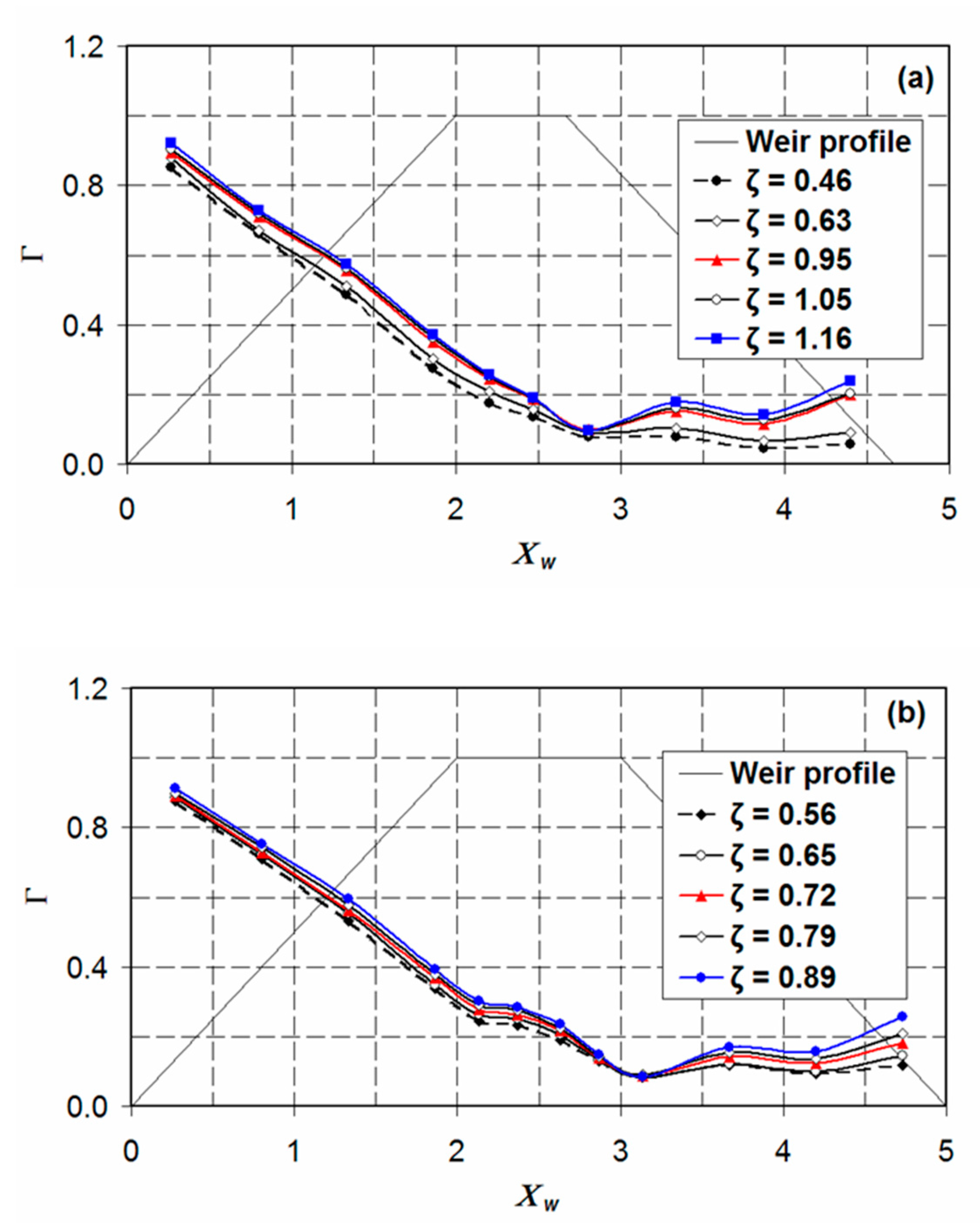
3.2. Variation of Bed Pressure

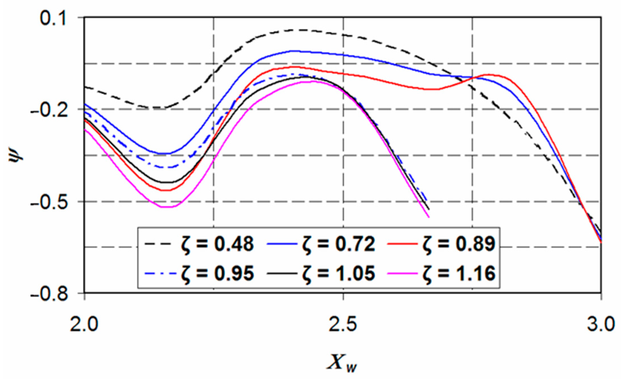
3.2.1. Minimum Bed Pressure

The experimental data of Zerihun [2] were employed to examine the effect of the vertical acceleration on the streamwise variation of bed pressure. Figure 3 shows the variation of the normalized bed-pressure profiles, Γ = p b / γ η 0 ( p b is the bed pressure, γ is the unit weight of the fluid), with the normalized horizontal distance Χ w ( = x / w ) . For the flow situation considered, the variation of the bed pressure in the transverse direction was insignificant. Consequently, all bed-pressure measurements were taken along the centerline of the trapezoidal-shaped weir. Owing to its inverse relation to the brink depth, h b , the slope of the downstream weir face affects the magnitude and location of the minimum bed pressure. As described by Bos [1], providing a slope steeper than 26.57° for the upstream and downstream faces of the trapezoidal-shaped weir triggers flow separation from the weir bottom. Due to flow separation, the minimum bed pressure occurs in the flow separation zone on the downstream weir face, as noted from the experimental results of Madadi et al. [31], Rouse [32] and Sargison and Percy [13] for broad-crested weir flow. For flows over a trapezoidal short-crested weir with a downstream-face slope less than 27°, only one absolute minimum bed pressure occurs at a tapping point near the downstream edge of the weir crest (see Figure 3). This is because of the curvilinear supercritical flow, which possesses a higher vertical acceleration due to the effect of the sharp streamline curvature in the vicinity of the downstream edge of the weir crest. As can be seen, the bed-pressure profiles are not self-similar.
The non-dimensional minimum bed pressure, Y = p m / p 0 ( p m is the minimum bed pressure, p 0 is the hydrostatic bed pressure), versus the relative overflow head, ζ , is shown in Figure 4. This figure also compares the minimum bed pressures for weirs having different crest lengths. For the cases considered here, the variation of the minimum bed pressure is approximated by a linear relation with a coefficient of determination R 2 > 0.85 , as shown in Figure 4. In the case of a long broad-crested weir, L and therefore, ζ 0 . The extrapolated minimum bed-pressure ratio approaches an average value of 0.40 for this weir with a downstream-face slope of less than 27°. Additionally, the result demonstrates the influence of the relative overflow head on the magnitude of the minimum bed pressure. All the minimum bed-pressure values are above the atmospheric pressure, as shown in Figure 3; Figure 4.

3.2.2. Dynamic Bed Pressure

The experimental data of Zerihun [2] were further analyzed to examine the variation of the normalized dynamic bed pressure, ψ = p D / p 0 ( p D is the dynamic bed pressure due to the vertical acceleration of the flow), over the crest of the weir. The results are shown in Figure 5. For ζ > 0.75 , the values of the dynamic bed pressure are negative along the crest due to the effect of the pronounced curvature of the convex-shaped free-surface profile. As expected, the magnitude of the dynamic pressure at a section increases with increasing the relative overflow head. Near the downstream crest edge, the dynamic pressure curve falls sharply due to the high vertical velocity of the supercritical flow caused by the strong streamline curvature. Consequently, the resulting maximum dynamic bed pressure in the convex flow region significantly reduces the magnitude of the total bed pressure, as depicted in Figure 3.

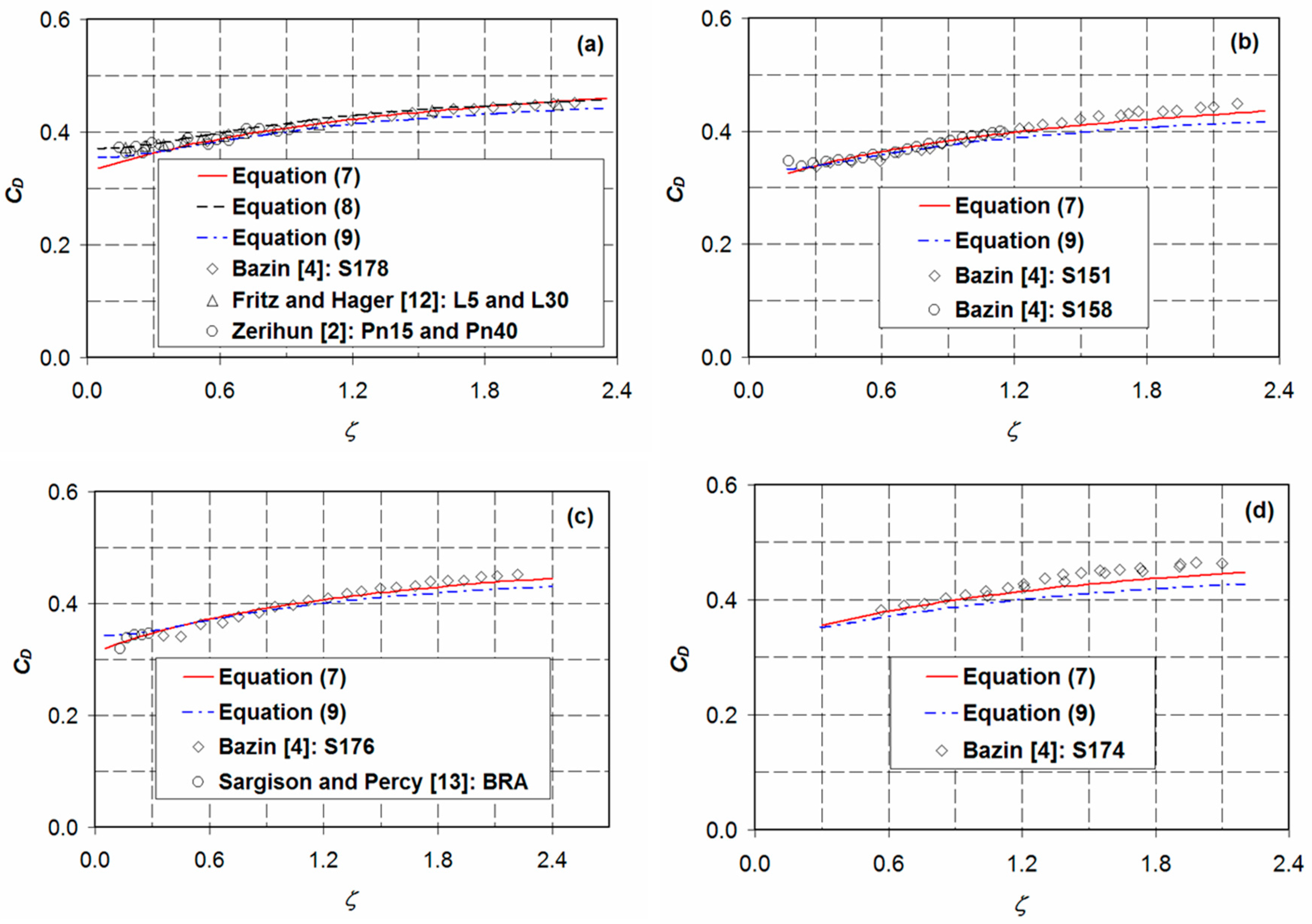
4. Free-Flow Coefficient of Discharge

For a weir with a rectangular control section, the relationship between head and discharge can be expressed as (see, e.g., [33]):
Q = C D 2 g B H 0 3 / 2 ,
where Q is the discharge; C D is the free-flow discharge coefficient which is commonly evaluated using the shallow-flow approach; and B is the width of the flow control section. Note that the free-flow discharge is related to the crest-referenced energy head, H 0 ( = h + h v , h v is the approach velocity head). Thus, its effect is implicitly incorporated in the above equation (see, e.g., [1,27,33,34]). Compared to a broad-crested weir, an accurate prediction of the discharge characteristics of a short-crested weir entails a discharge coefficient equation that accounts for the effects of the dynamic pressure of the flow.
Dimensional analysis demonstrates that the following variables are sufficient to describe the discharge characteristics of an hydraulically smooth trapezoidal-shaped weir provided that the effects of surface tension and viscosity are ignored. In functional notation,
C D = f n ( ζ ,   θ ,   φ ) ,
where θ and φ are the upstream- and downstream-face slopes, respectively, and f n ( ) is a functional relation. It is also assumed that the channel section is not very narrow ( B 300 mm), so that the effect of h / B is insignificant. After analyzing the dependency of C D on each of the above variables, the following free-flow discharge coefficient equation is proposed:
C D = k 1 + k 2 ( sin θ ) k 3 + k 4 ( sin φ ) k 5 + k 6 ζ 1 + k 7 ζ ,
where k 1 ,   k 2 , ,   k 7 are unknown constants. It is evident from the structure of Equation (6) that the last three terms account for the effects of the slopes of the upstream and downstream weir faces and the influence of the streamline curvature. For a broad-crested weir flow ( ζ < < 0.3 ), the contribution of the last term is insignificant. The proposed equation will be calibrated for the range of broad- and short-crested weirs ( 0.07 ζ 1.50 to 1.80, the upper limit depends on h / w ), so that it can be applied to determine the free-flow coefficients of discharge for both types of trapezoidal-shaped weirs (see, e.g., [1]).
The above constants are determined from the experimental data of Bazin [4] and Sargison and Percy [13] using a non-linear optimization technique which utilizes the generalized reduced gradient method [35]. Using Equation (4), the discharge coefficients for all the runs (for details, see Table 1) were computed with the experimental data of the weir discharge and the corresponding overflow heads at the upstream gaging station. These values were used to evaluate the errors associated with the assigned initial values of the constants. Using an optimization procedure, the sum of the square of the errors was minimized to give the following equation:
C D = 0.40 0.215   ( sin θ ) 22 / 125 + 0.13   ( sin φ ) 3 / 20 + 0.134 ζ 1 + 0.596 ζ .
The coefficient of determination and the root mean square error leading to the above equation are 0.91 and 1.11%, respectively. The result of the calibration is shown Figure 6, which compares the numerically computed discharge coefficient, C D n , with the experimental value, C D e . Note that all computed points fell in the error bandwidth of ±10%. It is pertinent to note that Equation (7) is limited to the ranges of the flow parameters indicated in Table 1. Additionally, it is restricted to free flow over a horizontal crest weir with h 50 mm.
The discharge coefficients computed from Equation (7) were validated using the experimental data of Bazin [4], Fritz and Hager [12], Sargison and Percy [13], and Zerihun [2] and also compared with the results of the earlier empirical equations introduced by Fritz and Hager [12] and Sargison and Percy [13]. The equation of Fritz and Hager [12] for free flow over a trapezoidal-shaped weir with both the upstream and downstream faces sloped at 26.57° is
C D = 0.43 + 0.06   [ sin π ( ε 0.55 ) ] ,
where ε = H 0 / ( L + H 0 ) . For free flow over a broad-crested weir, the above equation was extended by Sargison and Percy [13] to account for the effect of the upstream-face slope as
C D = 0.43 + 0.06   [ sin π ( ε 0.55 ) ] 0.0396 θ + 0.0029 ,
where θ is in radian. As shown in Figure 7, the agreement between the results of Equation (7) and the experimental data is relatively close, with maximum and mean relative errors of 6.53% and 1.70%, respectively. For the higher discharges ( ζ > 1.0 ) , the results of Equation (9) start to deviate from the measurements due to streamline curvilinearity, which is augmented by the effect of the downstream-face slope (see Figure 7b–d). This evidently demonstrates the influence of the dynamic effects of the flow on the discharge characteristics of a trapezoidal-shaped weir, as noted by Zerihun and Fenton [36]. Overall, the results of Equation (7) show a significant improvement over the predictions of Equation (9), especially for short-crested weir flows.

Effect of Weir Face Slopes

Figure 8 shows the discharge coefficient for trapezoidal-shaped weirs with varying upstream- or downstream-face slope. Note from Figure 8a that the analysis results clearly show the influence of the upstream-face slope on the discharge characteristics of short-crested weirs. For weirs with a vertical upstream face, the free-flow discharge coefficient attains a minimum value due to the effect of the energy dissipating turbulent eddies in the upstream flow separation zone. In contrast, increasing the downstream-face slope increases the free-flow discharge coefficient notably due to the predominant effect of the ever-increasing vertical acceleration of the flow over the crest of the weir (see Figure 8b). Such a dynamic pressure effect is a consequence of the high dependence of the brink depth on the slope of the downstream weir face. As demonstrated in Section 3.1, the free-surface profiles of a trapezoidal short-crested weir show self-similarity throughout the sub- and super-critical flow regimes. Consequently, the ratio of brink depth to critical flow depth is nearly constant, independent of the weir discharge. However, varying the weir geometry results in different values of this ratio (see, e.g., [37]) and the free-flow discharge coefficient. For flows in a channel transition from mild to steep slopes, Weyermuller and Mostafa [38] presented similar investigation results for the effects of the downstream slope on the brink depth.

5. Conclusions

By considering the advantage of its higher hydraulic efficiency compared to a broad-crested weir with vertical faces, the salient features of a curvilinear transcritical flow over a trapezoidal-shaped weir with sharp-crested edges have been systematically investigated. A large set of experimental data from the literature were synthesized, and a practical solution to the problem of the free-flow discharge characteristics of this type of weir was obtained. As a part of data synthesis, size-scale effects on the experimental data were examined based on the criteria recommended by Curtis [28] and Hager [24]. Accordingly, the uncertainties of the flow variable measurement due to smaller model sizes are eliminated.
An attempt to generalize the equation of the axial free-surface profiles for flows over a short-crested weir with sloping upstream and downstream faces has been made. For flows with relative overflow heads ranging from 0.50 to 1.20, the variation of the normalized free-surface elevation is approximately described by a hyperbolic tangent equation. The application of this equation is limited to flows over a symmetrical weir with θ = φ = 26.57°. The result suggests that the nearest gaging station for the correct measurement of the overflow depth under free-flow conditions is at η 0 ( = h + w ) from the upstream edge of the weir. Upstream of this station, a hydrostatic flow situation prevails. Furthermore, the analysis of the pressure data reveals that for a trapezoidal short-crested weir with a downstream-face slope less than 27°, only one absolute minimum bed pressure occurs near the downstream edge of the weir crest. This is due to the effect of the curvilinear supercritical flow which possesses a higher vertical acceleration as a result of the strong streamline curvature.
For the free-flow discharge coefficient, an empirical equation accounting for the effects of the weir geometry and the streamline curvature was proposed. The results of the validation confirm that the proposed equation is capable of predicting the discharge coefficient of a horizontal crest weir under free-flow conditions with an accuracy of approximately ±6.5%. This equation is valid for hydraulically smooth flows with the ranges of parameters listed in Table 1. Additionally, the results reveal that both the upstream- and downstream-face slopes significantly affect the discharge coefficient of a short-crested weir. The overall results of the study suggest that the empirical equation can be applied to determine the free-flow coefficients of discharge for broad- and short-crested types of trapezoidal-shaped weirs. Such an equation is generally recommended for high-head prototype applications where size-scale effects are likely insignificant.

Funding

This research received no external funding.

Conflicts of Interest

The author declares no conflict of interest.

Nomenclature

B width of the flow control section [L]
C D discharge coefficient [-]
C D e observed discharge coefficient [-]
C D n computed discharge coefficient [-]
F 0 approach Froude number [-]
g gravitational acceleration [LT−2]
h approach overflow depth [L]
h b brink depth [L]
h v approach velocity head [L]
H flow depth [L]
H 0 upstream crest-referenced energy head [L]
L weir crest length [L]
p b bed pressure [ML−1T−2]
p D dynamic bed pressure [ML−1T−2]
p 0 hydrostatic bed pressure [ML−1T−2]
p m minimum bed pressure [ML−1T−2]
Q discharge [L3T−1]
R 2 coefficient of determination [-]
w height of the weir crest [L]
x horizontal coordinate [L]
y transverse coordinate [L]
z vertical coordinate [L]
Γ normalized bed pressure [-]
γ unit weight of the fluid [ML−2T−2]
ε = H 0 / ( H 0 + L ) [-]
ζ relative overflow head [-]
η free-surface elevation [L]
η 0 free-surface elevation at the gaging station [L]
η x slope of the free surface [-]
θ slope of the upstream weir face [deg]
κ curvature of the free surface [L−1]
λ relative free-surface curvature [-]
φ slope of the downstream weir face [deg]
Χ or Χ w non-dimensional horizontal distance [-]
ψ normalized dynamic bed pressure [-]
Ω normalized free-surface elevation [-]
ω = 1 + η x 2 [-]

References

  1. Bos, M.G. Discharge Measurement Structures, 3rd ed.; International Institute for Land Reclamation and Improvement: Wageningen, The Netherlands, 1989; pp. 28–121. [Google Scholar]
  2. Zerihun, Y.T. A One-Dimensional Boussinesq-Type Momentum Model for Steady Rapidly-Varied Open-Channel Flows. Ph.D. Thesis, The University of Melbourne, Melbourne, Australia, 2004. [Google Scholar]
  3. Zerihun, Y.T.; Fenton, J.D. A Boussinesq-type model for flow over trapezoidal profile weirs. J. Hydr. Res. 2007, 45, 519–528. [Google Scholar] [CrossRef]
  4. Bazin, H. Expériences Nouvelles sur L’écoulement en Déversoir (Recent Experiments on the Flow of Water over Weirs); Dunod: Paris, France, 1898. (In French) [Google Scholar]
  5. Sigurdsson, G. Discharge Characteristics of an Embankment-Shaped Weir. Master’s Thesis, Georgia Institute of Technology, Atlanta, GA, USA, 1955. [Google Scholar]
  6. Kindsvater, C.E. Discharge Characteristics of Embankment-Shaped Weirs; Geological Survey Water-Supply Paper 1617-A; U.S. Government Printing Office: Washington, DC, USA, 1964.
  7. Skogerboe, G.V.; Hyatt, M.L.; Austin, H.L. Stage-Fall-Discharge Relations for Flood Flows over Highway Embankments; Report PR-WR6-7; Utah Water Research Laboratory, College of Engineering, Utah State University: Logan, UT, USA, 1966. [Google Scholar]
  8. Hager, W.H. Breitkroniger überfall (Broad-crested weir). Wasser-Energie-Luft. 1994, 86, 363–369. (In German) [Google Scholar]
  9. Hager, W.H.; Schwalt, M. Broad-crested weir. J. Irrig. Drain. Eng. 1994, 120, 13–26. [Google Scholar] [CrossRef]
  10. Hakim, S.S.; Azimi, A.H. Hydraulics of submerged triangular weirs and weirs of finite-crest length with upstream and downstream ramps. J. Irrig. Drain. Eng. 2017, 143. [Google Scholar] [CrossRef]
  11. Pinto, N.-L.de S.; Ota, J.J. Distribuição das pressões na face de jusante das barragens de enrocamento submersas—Investigação experimental (Pressure distribution on the downstream face of submerged rockfill dams—Experimental investigation). Em Procedimentos do dia IX Congresso Latinoamericano Hidráulica, Mérida, Venezuela, 30 Junho–4 Julho 1980; pp. 529–540. (In Portuguese). [Google Scholar]
  12. Fritz, H.M.; Hager, H.W. Hydraulics of embankment weirs. J. Hydr. Eng. 1998, 124, 963–971. [Google Scholar] [CrossRef]
  13. Sargison, J.E.; Percy, A. Hydraulics of broad-crested weirs with varying side slopes. J. Irrig. Drain. Eng. 2009, 135, 115–118. [Google Scholar] [CrossRef]
  14. Salmasi, F.; Abraham, J. Discharge coefficients for ogee weirs including the effects of a sloping upstream face. Water Supply 2020, 20, 1493–1508. [Google Scholar] [CrossRef]
  15. Azimi, A.H.; Rajaratnam, N.; Zhu, D.Z. Discharge characteristics of weirs of finite-crest length with upstream and downstream ramps. J. Irrig. Drain. Eng. 2013, 139, 75–83. [Google Scholar] [CrossRef]
  16. Felder, S.; Islam, N. Hydraulic performance of an embankment weir with rough crest. J. Hydr. Eng. 2016, 142, 04016086. [Google Scholar] [CrossRef]
  17. Pařílková, J.; Říha, J.; Zachoval, Z. The influence of roughness on the discharge coefficient of a broad-crested weir. J. Hydrol. Hydromech. 2012, 60, 101–114. [Google Scholar] [CrossRef] [Green Version]
  18. Di Stefano, C.; Ferro, V.; Bijankhan, M. New theoretical solution of the outflow process for a weir with complex shape. J. Irrig. Drain. Eng. 2016, 142. [Google Scholar] [CrossRef]
  19. Hargreaves, D.M.; Morvan, H.P.; Wrigth, N.G. Validation of the volume of fluid method for free-surface calculation: The broad-crested weir. Eng. Appl. Comput. Fluid Mech. 2007, 1, 136–147. [Google Scholar] [CrossRef] [Green Version]
  20. Soydan-Oksal, N.G.; Akoz, M.S.; Simsek, O. Numerical modeling of trapezoidal weir flow with RANS, LES and DES models. Sādhanā 2020, 45. [Google Scholar] [CrossRef]
  21. Xu, T.; Jin, Y.-C. Numerical study of the flow over broad-crested weirs by a mesh-free method. J. Irrig. Drain. Eng. 2017, 143. [Google Scholar] [CrossRef]
  22. Fathi-Moghaddam, M.; Tavakol-Sadrabadi, M.; Rahmanshahi, M. Numerical simulation of the hydraulic performance of triangular and trapezoidal gabion weirs in free-flow condition. Flow Meas. Instrum. 2018, 62, 93–104. [Google Scholar] [CrossRef]
  23. Hager, W.H. Experiments on standard spillway flow. Proc. Instn. Civ. Eng. 1991, 91, 399–416. [Google Scholar]
  24. Hager, W.H. Dammüberfälle (Dam overflows). Wasser und Boden. 1994, 45, 33–36. (In German) [Google Scholar]
  25. Lakshmana Rao, N.S. Theory of Weirs. In Advances in Hydroscience; Chow, V.T., Ed.; Academic Press: New York, NY, USA, 1975; Volume 10, pp. 310–406. [Google Scholar]
  26. Schmocker, L.; Halldórsdóttir, B.R.; Hager, W.H. Effect of weir face angles on circular-crested weir flow. J. Hydr. Eng. 2011, 137, 637–643. [Google Scholar] [CrossRef]
  27. Tracy, H.J. Discharge Characteristics of Broad-Crested Weirs; U.S. Department of the Interior, Geological Survey Circular 397: Washington, DC, USA, 1957.
  28. Curtis, K.W. Size-Scale Effect on Linear Weir Hydraulics. Master’s Thesis, Utah State University, Logan, UT, USA, 2016. [Google Scholar]
  29. Clemmens, A.J.; Wahl, T.L.; Bos, M.G.; Replogle, J.A. Water Measurement with Flumes and Weirs; International Institute for Land Reclamation and Improvement: Wageningen, The Netherlands, 2001; pp. 131–132. [Google Scholar]
  30. Goodarzi, E.; Farhoudi, J.; Shokri, N. Flow characteristics of rectangular broad-crested weirs with sloped upstream face. J. Hydrol. Hydromech. 2012, 60, 87–100. [Google Scholar] [CrossRef] [Green Version]
  31. Madadi, M.R.; Dalir, A.H.; Farsadizadeh, D. Investigation of flow characteristics above trapezoidal broad-crested weirs. Flow Meas. Instrum. 2014, 38, 139–148. [Google Scholar] [CrossRef]
  32. Rouse, H. The Distribution of Hydraulic Energy in Weir Flow in Relation to Spillway Design. Master’s Thesis, Massachusetts Institute of Technology, Boston, MA, USA, 1932. [Google Scholar]
  33. Horton, R.E. Weir Experiments, Coefficients, and Formulas; Water-Supply and Irrigation Paper No. 200; U.S. Geological Survey, Government Printing Office: Washington, DC, USA, 1907.
  34. Hager, W.H. Wastewater Hydraulics–Theory and Practice, 2nd ed.; Springer: Berlin/Heidelberg, Germany, 2010; pp. 298–300. [Google Scholar]
  35. Lasdon, L.S.; Fox, R.L.; Ratner, M.W. Non-linear optimization using the generalized reduced gradient method. Revue Fr. d’Automatique Inform. Rech. Opér. 1974, 3, 73–103. [Google Scholar]
  36. Zerihun, Y.T.; Fenton, J.D. Application of a Boussinesq-type equation to flow over trapezoidal profile weirs. In Proceedings of the International Conference on Hydraulics of Dams and River Structures, Tehran, Iran, 26–28 April 2004; Yazdandoost, F., Attari, J., Eds.; Taylor and Francis Group: London, UK; pp. 369–376. [Google Scholar]
  37. Neogy, B.N. Brink depth for trapezoidal broad-crested weir. J. Hydr. Div. 1972, 98, 2171–2189. [Google Scholar]
  38. Weyermuller, R.G.; Mostafa, M.G. Flow at grade-break from mild to steep slopes. J. Hydr. Div. 1976, 102, 1439–1448. [Google Scholar]
Figure 1. (a) Definition sketch for weir flow; and (b) transcritical flow over a trapezoidal short-crested weir, after Zerihun [2]. The overflow depth, brink depth and height of the weir crest are denoted by h , h b and w , respectively, and EGL stands for the energy grade line. The Cartesian coordinates ( x , z ) are also shown.
Fluids 05 00238 g001
Figure 2. (a) Normalized free-surface profiles Ω ( Χ ) for various values of relative overflow head ζ (experimental data of test series Pn10 and Pn15 from Zerihun’s [2] experiments); and (b) streamwise variation of the relative curvature of the free surface λ ( Χ ) .
Fluids 05 00238 g002aFluids 05 00238 g002b
Figure 3. Variation of the normalized bed pressure Γ with the normalized horizontal distance Χ w for various values of relative overflow head ζ . The experimental data are from the test series (a) Pn10 and (b) Pn15.
Fluids 05 00238 g003
Figure 4. Normalized minimum bed pressure Y as a function of ζ for transcritical flows over trapezoidal-shaped weirs. The data of test series Pn10, Pn15, and Pn40 are indicated by black, blue, and red symbol colors, respectively.
Fluids 05 00238 g004
Figure 5. Streamwise variation of the normalized dynamic bed pressure ψ ( Χ w ) for various values of relative overflow head ζ . The computed profiles are based on the experimental data of series Pn10 and Pn15.
Fluids 05 00238 g005
Figure 6. Comparison of predicted and measured discharge coefficients for flows over hydraulically smooth trapezoidal-shaped weirs under free-flow conditions. The downstream-face slope varies from 9.46° to 90°.
Fluids 05 00238 g006
Figure 7. Discharge coefficients for hydraulically smooth trapezoidal-shaped weirs with various combinations of upstream- and downstream-face slopes [ θ , φ ]: (a) [26.57°, 26.57°]; (b) [63.43°, 26.57°]; (c) [45°, 26.57°]; and (d) [45°, 45°].
Fluids 05 00238 g007
Figure 8. Typical variation of free-flow discharge coefficient with the (a) upstream- and (b) downstream-face slopes for various values of relative overflow head ζ . φ and θ in (a) and (b), respectively, kept at 26.57°.
Fluids 05 00238 g008
Table 1. Summary of scope of experimental studies.
Experiments θ φ ζ h / ( h + w ) F 0
1. Bazin [4]
Series (S) [147, 149, 150, 151, 153, 154, 156, 158–160, 171, 174, 176, 178]
26.57°–90°9.46°–45°0.13–2.260.08–0.370.01–0.21
2. Fritz and Hager [12]
Series [L5 (L = 50 mm), L30 (L = 300 mm)]
26.57°26.57°0.17–2.130.15–0.260.03–0.15
3. Sargison and Percy [13]
Series [ARB, BRA, BRV]
26.57°–45°26.57°–90°0.13–0.300.21–0.370.04–0.12
4. Zerihun [2]
Series [Pn10, Pn15, Pn40]
26.57°26.57°0.14–0.920.23–0.410.06–0.19
Publisher’s Note: MDPI stays neutral with regard to jurisdictional claims in published maps and institutional affiliations.

