Article

Effect of Functional Surfaces with Gradient Mixed Wettability on Flow Boiling in a High Aspect Ratio Microchannel

by
Vahid Ebrahimpour Ahmadi
1,2,
Akam Aboubakri
1,2,
Abdolali Khalili Sadaghiani
1,2,
Khellil Sefiane
3 and
Ali Koşar
1,2,4,*
1
Faculty of Engineering and Natural Science, Sabanci University, 34956 Istanbul, Turkey
2
Sabanci University Nanotechnology and Applications Center (SUNUM), Sabanci University, 34956 Istanbul, Turkey
3
School of Engineering, University of Edinburgh, Edinburgh EH8 9YL, UK
4
Center of Excellence for Functional Surfaces and Interfaces for Nano-Diagnostics (EFSUN), Sabanci University, 34956 Istanbul, Turkey
*
Author to whom correspondence should be addressed.
Fluids 2020, 5(4), 239; https://doi.org/10.3390/fluids5040239
Submission received: 1 November 2020 / Revised: 2 December 2020 / Accepted: 7 December 2020 / Published: 10 December 2020
(This article belongs to the Special Issue Recent Advances in Single and Multiphase Flows in Microchannels)

Abstract

:
Flow boiling is one of the most effective phase-change heat transfer mechanisms and is strongly dependent on surface properties. The surface wettability is a crucial parameter, which has a considerable effect on the heat transfer performance, particularly in flow boiling. The contact angle determines the number of nucleation sites as well as bubble dynamics and flow patterns. This study introduces three new generation mixed wettability surfaces and compares them with a wholly hydrophobic surface reference sample, in flow boiling in a high aspect ratio microchannel. The mixed wettability substrates have five regions as fully Al2O3, (hydrophobic zone) region, three different patterned configurations with various A* values, and fully SiO2 (hydrophilic zone) region, where A* is defined as A Al2O3/A total (hydrophobicity ratio). Boiling heat transfer results were obtained for each surface at various wall heat fluxes and three different mass fluxes. According to the obtained results, significant enhancements in heat transfer (by up to 56.7%) could be obtained with biphilic surfaces compared to the reference sample (hydrophobic surface). Performed flow visualization proves that the tested biphilic surfaces enhance heat transfer by reducing the bubbly flow regime and extending the slug regime.

1. Introduction

Along with rapid developments in emerging technologies, such as high-power electronic devices and power generation systems, the increasing trend in generated heat has become a noticeable issue in such systems. An efficient heat dissipation system can enhance the safety, performance and reliability of miniature systems involving high power density [1]. Major cooling techniques in thermal management are natural convection [2], forced convection utilizing mechanical air-handling equipment [3,4], or convection with phase change phenomena [1,5,6,7,8,9]. Boiling heat transfer is an effective cooling mechanism, where a considerable amount of heat can be dissipated through heating and vaporization (phase change process) of the coolant. Boiling heat transfer including both pool and flow boiling offers high heat transfer coefficients (HTC), which are caused by sensible and latent heating of the coolant [6].
Flow boiling is one of the most effective phase-change heat transfer phenomena [10] providing high energy efficiency [11]. In flow boiling, surface properties influence bubble nucleation, growth and departure processes. In small domains, the surface forces become predominant [5]. Thanks a to the advances in micro-electromechanical systems (MEMS) fabrication techniques, the effect of enhanced surfaces with different geometrical parameters on heat transfer, bubble dynamics, pressure drop and flow patterns could be investigated [12].
In a small channel filled with flowing fluid, the bubble formation on the heated internal surface determines flow patterns [1]. The generated bubbles and their distribution in flow boiling could be altered by several parameters including subcooling temperature [13], surface properties [14], and channel dimensions [15]. In one of the related studies, Harirchian et al. [16] conducted flow boiling experiments on a microchannel and observed five different flow patterns (i.e., bubbly, slug, churn, wispy-annular, and annular) at different heat and mass fluxes. According to the study of Tibirica et al. [17], bubble departure diameter and quality decreased with mass flux. At high mass fluxes, the transition from slug to annular flow pattern was not visible. Wang and Cheng [18] reported that different flow patterns formed at different local wall temperatures. Through simultaneous temperature data acquisition and flow visualization, they demonstrated that the average wall temperatures for bubbly flow were lower than annular flow. The study of Lin and Jia [19], which included flow boiling experiments in a rectangular channel, illustrated that vapor quality affected heat transfer rate. Due to the generation of an insulating layer, the HTC value decreased in the high-vapor quality region. Alam et al. [20] compared the magnitude of different forces acting near the triple contact line of a nucleated bubble and reported that inertial and surface tension forces are the dominating forces. Frost and Kippenhan [21] initially demonstrated the impact of surface tension on boiling heat transfer and then enhanced heat transfer by adding surface active agents to the bulk fluid, which reduced the surface tension.
Some studies investigated the surface wettability as a critical parameter [5,22] in small domains. Kandlikar [23] investigated the influence of surface wettability and working fluid in a vertical pool boiling experiment. Based on this study, critical heat flux (CHF) values decreased to zero by increasing the contact angle (CA) to 180°. A similar result was obtained with a horizontal pool boiling experiment, where nano-silica coating was introduced on a copper surface [24]. Accordingly, pool boiling curve shifted to larger wall superheats, which suggested decreased CHF. These findings also proved that the results drastically changed with surface wettability. Li et al. [25] theoretically and experimentally examined the effect of wettability on hydrophilic surfaces. They suggested a semi-analytical model for pool boiling, which could fairly estimate heat flux. This model utilized correlations involving surface wettability for departure frequency, diameter, and site density. Zhou et al. [26] conducted flow boiling experiments and evaluated the impact of CA for two surfaces involving bare hydrophobic silicon (CA = 65°) and treated superhydrophilic surface with a contact angle of less than 5°. The flow visualization study proved that local dry-out happened on the untreated hydrophilic surface at high heat fluxes for low mass fluxes. However, this phenomenon did not occur on the super-hydrophilic surface under the same condition. Searle et al. [27] examined the influence of the microstructure geometry for superhydrophobic substrates on pool boiling. Betz et al. [28] examined superhydrophobic, superhydrophilic, biphilic, and superbiphilic surfaces in pool boing tests. They demonstrated the nucleation site density increased with CA (reducing wettability), which increased HTC for hydrophobic and superhydrophobic surfaces.
The mixed wettability or biphilic surfaces have become a promising topic in boiling heat transfer because of their potential for achieving high heat flux cooling. In one of the studies, Motazakker et al. [29] defined A* as the ratio of hydrophobic area to the total area for biphilic surfaces and found that there existed an optimum ratio (38.46% in their study on pool boiling), which could provide the best heat transfer performance. Yamada et al. [30] studied pool boiling on biphilic surfaces under sub-atmospheric conditions. Zupancic et al. [31] investigated pool boiling on laser-made hydrophobic/superhydrophilic polydimethylsiloxane-silica surfaces. Aboubakri et al. [32] investigated the impact of mixed wettability surfaces on the heat transfer performance for evaporative droplets. Betz et al. [28] reported that the biphilic surfaces exhibited the largest HTC. They also developed an analytical model for explaining how these surfaces could delay CHF and raise HTC at the same time by regulating the vapor and liquid transportation. Gong and Cheng [33] conducted a numerical study using the Lattice Boltzmann method to analyze mixed wettability in pool boiling. They demonstrated that hydrophobic spots on hydrophilic surfaces enhanced bubble nucleation, which could improve boiling heat transfer and decrease the nucleation time. Similar to previous studies, they also reported that surfaces with mixed wettability could better manage the vapor distribution over the heater wall and consequently delay CHF.
While many studies evaluated the effect of surface wettability in pool boiling experiments, studies on flow boiling are rather scarce. In particular, the number of research efforts on surfaces with mixed wettability is noticeably insufficient, and further investigation on this topic is needed. In this regard, this study includes flow boiling experiments on surfaces with different wettability gradients along a small channel. Since vapor distribution in two-phase flows plays a critical role in heat transfer, flow regime transitions, bubble coalescence and bubble breakup along the microchannel were assessed using a high-speed camera system. The tested samples were designed to reveal the effect of surface biphilicity variation along the channel on bubble dynamics and flow boiling pattern change. Experiments were performed at different heat and mass fluxes to explore the effect of mixed wettability on boiling heat transfer performance and compared with the obtained results on a wholly hydrophobic surface, which constitutes the base for comparison.

2. Experimental Setup, Procedure, and Data Reduction

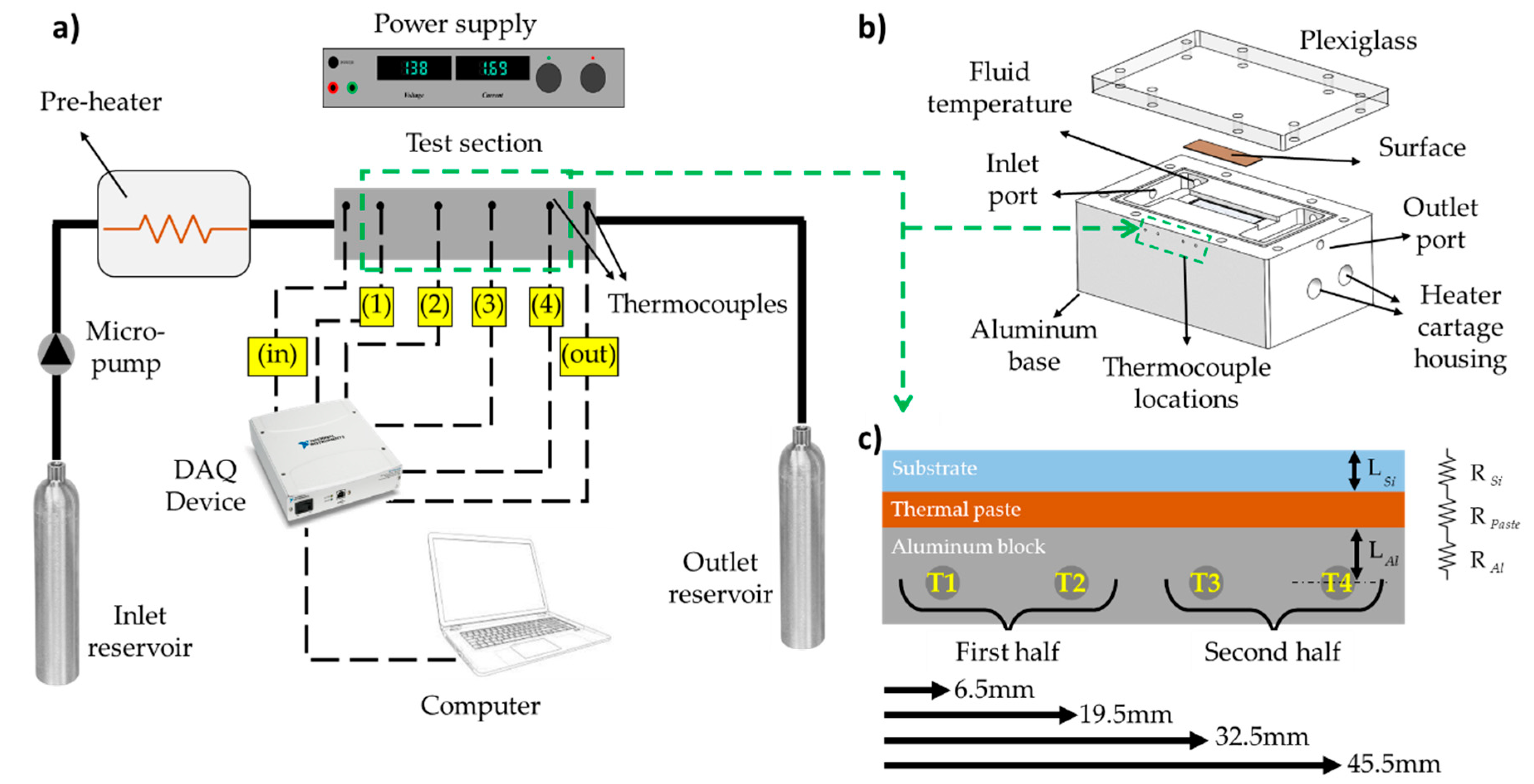
2.1. Experimental Setup and Test Section

The open loop experimental setup is shown in Figure 1a. It consists of a precise micropump, a reservoir, regulating valves, temperature and pressure sensors, a preheater, and the test section is shown in Figure 1b. The test section houses an aluminum block for conduction heating, a Teflon block for insulation, test specimens/samples, and a transparent cover for visualization. The Aluminum block was used for conduction heating, mainly due to its high machinability and thermal conductivity. In the Aluminum base, two cartridge heaters were placed, each of length 31.25 mm and of diameter 6.25 mm. The heater and the surfaces were treated with thermal paste to reduce the thermal resistance. The test specimens were placed in the designated area (i.e., 51.8 mm × 15.3 mm) top of the aluminum block. Moreover, the depth of the channel is 500 μm. At the top, a transparent cover (plexiglass) was used to seal the test section and to perform visualization studies. Sealings were used at different locations to ensure sealing in the system. A sandwich mechanism was used to hold the parts together. Surface temperatures of the tested samples were obtained along the channel at four different locations. Experimental data points were gathered under steady state conditions, and heat flux and surface temperatures were acquired through the data acquisition system. Figure 1c shows the thermal resistance network for surface temperature determination. Also, as shown in Figure 1c T1 and T2, and T3 and T4 thermocouples were used for calculating the boiling heat transfer coefficient in the first and second half the channel, respectively.

2.2. Experimental Procedure

De-ionized water was used as the working fluid in flow boiling experiments. During the experiments, the flow rate was set to the desired value using the pump and checked at two different locations of the setup. Before entering to the test section, the water passed through a pre-heater to increase the inlet temperature for different subcooling values. The inlet temperature of the test section was carefully measured to make sure that the system was under the steady state condition before conducting the experiments. The temperature of inlet subcooled water for mass fluxes of 40 kg.m−2.s−1, 80 kg.m−2.s−1, and 120 kg.m−2.s−1 were 68.3 °C, 70.1 °C, and 72.2 °C, respectively. The applied power was increased gradually. The temperatures were acquired under steady state conditions. The average value measured from the first and the second thermocouple locations in the experimental setup was considered as the average temperature of the first half of the channel. Similarly, the temperatures obtained from the third and fourth thermocouple locations were used to obtain the average temperature of the second half. This process was repeated for each flow rate. Each test was repeated three times to ensure the repeatability of the experiments. The average of the obtained data from the experiments was used in data reduction. To estimate heat losses, electrical power was applied to the test section, while the working fluid was evacuated. Once the temperature of the test section became steady, the temperature differences between the test section and the ambient were recorded. These data were used to obtain a calibration curve for a heat loss. Accordingly, heat losses were utilized to find the net applied power for each data point. According to the obtained results from this section, the average heat loss during the experiments is 14% of the applied power.

2.3. Data Reduction

The local and average heat transfer coefficients of the experiments are deduced from voltage, current, flow rate, and temperature data acquired during the experiments.
Mass flux G is calculated as:
G = m ˙ A c
where m ˙   is the mass flow rate (kg.s−1), and A c   is the cross sectional area of the microchannel (m2). Using the applied voltage and current values, the electrical power imposed to the system is calculated as:
P = V . I
where P is the applied power (W), and V and I are the measured voltage (V) and current (A), respectively. Considering some percentage of heat loss, the applied heat flux to the working fluid can be expressed as:
q = ( P Q ˙ l o s s ) A s
where Q ˙ l o s s is the heat loss, and A s is the area of the heated surface.
The heat transfer coefficient can be expressed as:
h = q ( T w T f )
where T W is the temperature of the heated surface (K), and T f is the temperature of the working fluid (K). With the known applied heat flux and thermal resistances (Figure 1c), the temperatures of the surface are found as:
T w , j = T j q ( L A l K A l + R P + L S i K S i )
where T w , j is the temperature of the substrate at the jth location (j = 1 to 4), T j is the temperature read from the jth thermocouple location. Moreover, L A l and L S i are the thickness of aluminum and silicon samples, respectively, while K A l and K S i are the thermal conductivity of the aluminum block and silicon wafer, respectively, and R P is the thermal resistance of the thermal paste.
For subcooled boiling experiments, the fluid temperature is calculated via energy equation (Equation (5)) and for saturated boiling experiments fluid temperature is set to saturation temperature. Considering the constant heat flux applied to the system, the temperature of the fluid can be obtained as:
T f , x = T i + q . A x m ˙ c p
where T i is the inlet temperature (K), and c p is specific heat capacity of the fluid (J.kg−1K−1). Moreover, A x is the heat area starting from inlet, to the point of interest. Using the uncertainty analysis proposed by Coleman and Steel [34], the uncertainties in the experimental parameters could be obtained and are summarized in Table 1.

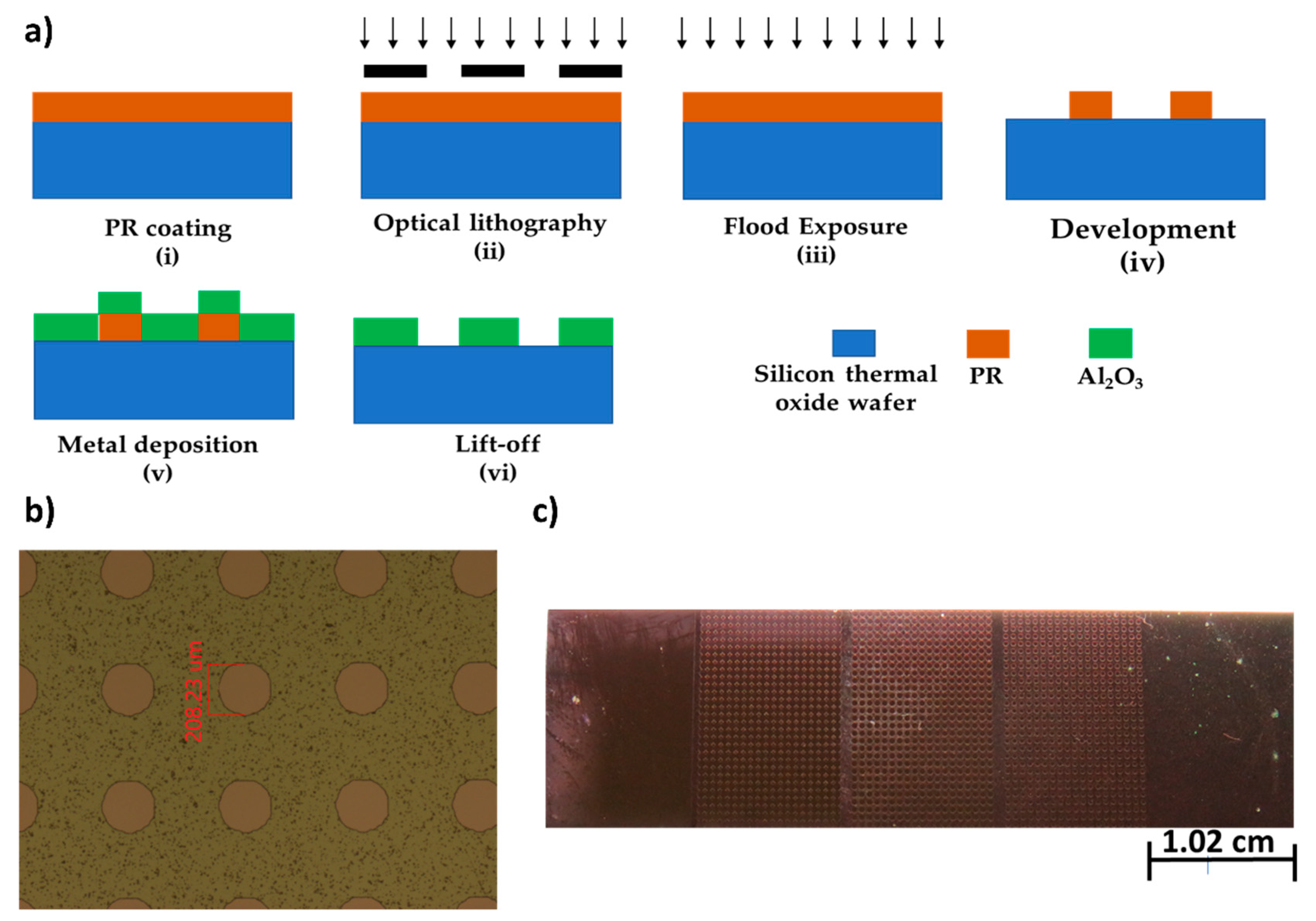
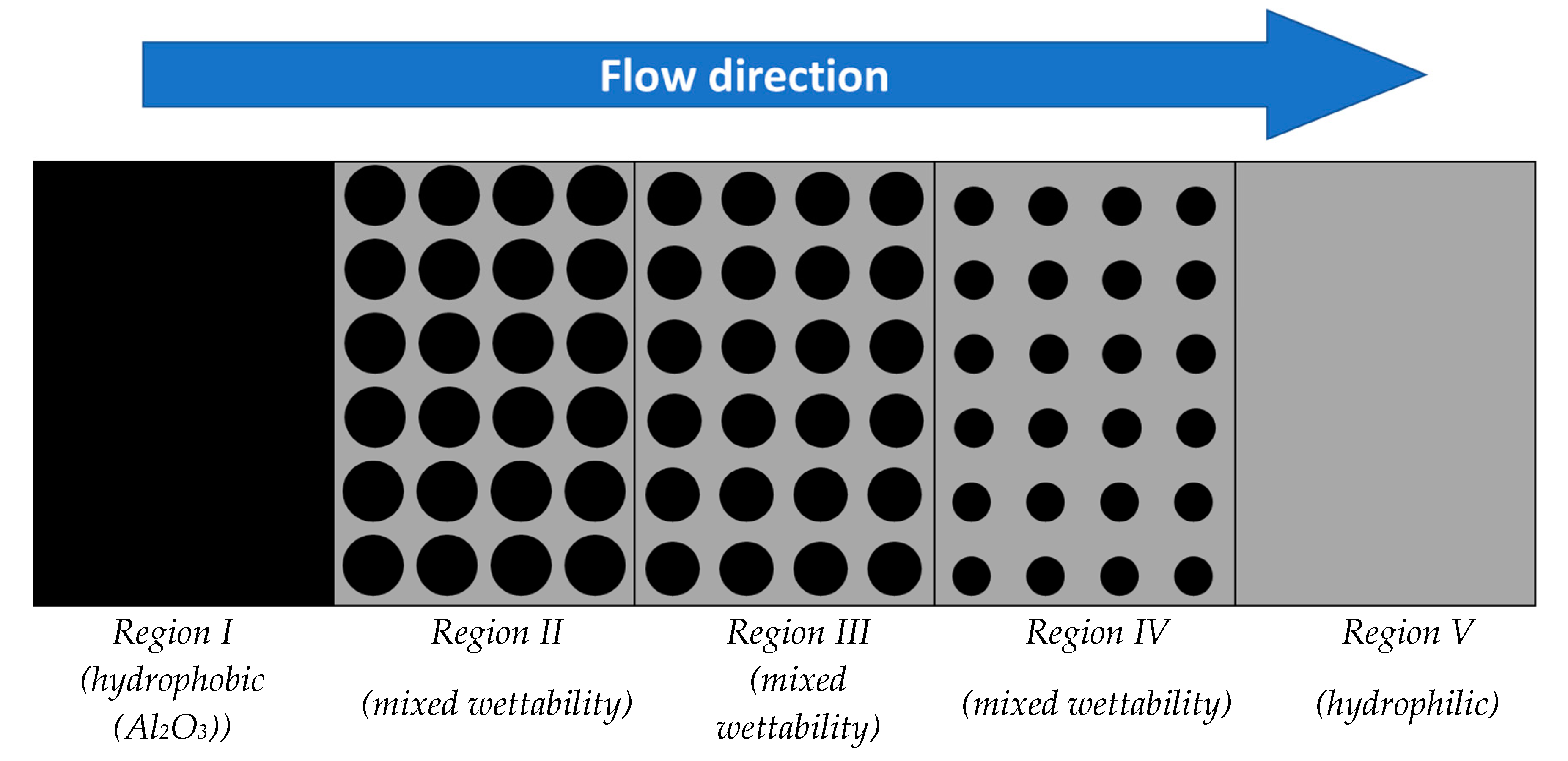
3. Sample Preparation and Characterization
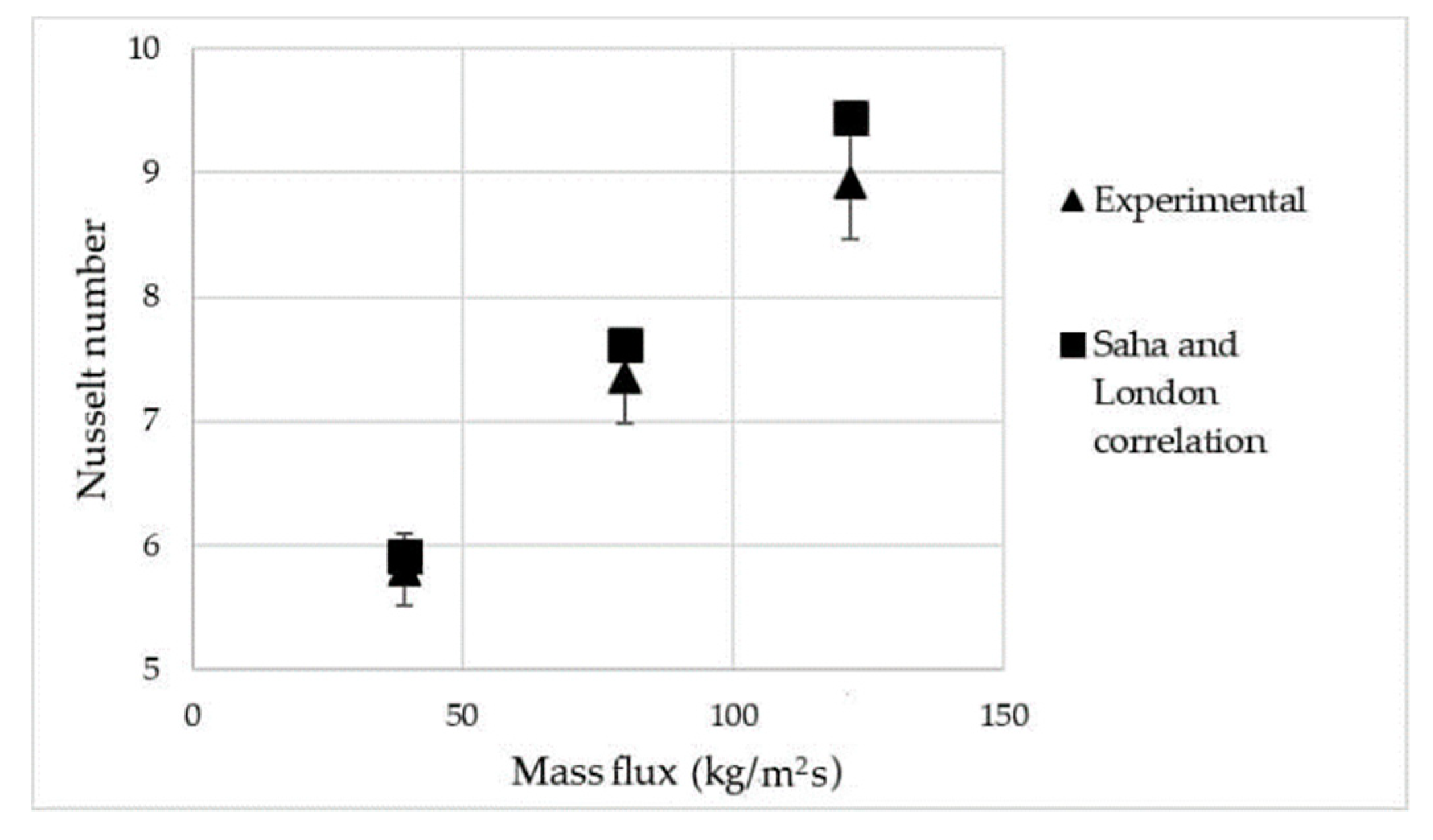
The silicon thermal oxide wafers, where silicon dioxide layer was formed on a bare silicon surface at increased temperature, were used in this study. In order to make sure that the wafers were without any contaminations, they were cleaned with acetone, isopropanol and DI water, and then blown with N2 gas. The wafers were completely dried out by putting on the hot plate for a few minutes. The lift-off process was applied for the fabrication of the surfaces. Figure 2a shows the fabrication process flow. Firstly, the AZ 4562 photoresist (PR), which possesses the image reversal feature, was coated on the silicon thermal oxide wafer at 4000 rpm for 30 s with an angular acceleration of 200 rpm/s (i). In the subsequent soft bake process, after waiting for a few minutes at the room temperature, the wafer was put on the hot plate for 50 s at 110 °C, which enhanced the bonding of sample and photoresist. The next step was the UV light exposure (350 mJ/cm2) using a mask aligner UV-Lithography device through the image reversal photomasks printed on acetate (ii). Then, the wafer was baked at for 120 s at 110 °C. In order to utilize the image reversal feature of AZ 5214, the UV light was applied for 15 s on to the wafer without any acetate mask (iii). The AZ 726 MIF developer was used to develop the sample (iv). The last step was the post bake process of wafer for 50 s at 110 °C and cooling down at room temperature.
Next, Al2O3 layer was deposited on the samples through the e-beam evaporation. The thickness of the deposited layer is 200 nm (v). Afterwards, the wafer was immersed in the acetone and water for a few minutes (vi). After the lift-off process, the substrate was washed and dried with N2 gas. Figure 2b,c show one of the fabricated surfaces and the microscopic view of designed patterns, respectively. In Figure 3, the black islands represent the aluminum oxide spots, and the gray parts correspond to silicon oxide. Moreover, as shown, the samples are divided into five regions: the fully Al2O3, three patterned configurations, and fully SiO2, respectively, from left to right. The measured contact angles for the SiO2 and Al2O3 parts are 57° and 87°, respectively. It is worth mentioning that, since the second one is considerably close to the contact angle corresponding to the hydrophobic threshold, we called it the hydrophobic part.
Overall, in addition to the wholly hydrophobic surface (Al2O3), which is the base of comparison in this study, three different samples were designed and fabricated according to the mentioned process. Table 2 summarizes the features of these substrates (i.e., Sample #1, #2, #3), where A* and D stand for A hydrophob/A total and circle diameters in the designed patterns, respectively.

4. Validation

Prior to boiling heat transfer experiments, to make sure that the experimental set-up works without any flaw and the obtained results are reliable, single-phase heat transfer tests were performed.
For this, the heat flux applied to the fluid and the temperature of the working fluid was measured at the inlet and outlet. Knowing the inlet and out temperatures, the transferred heat to the fluid was calculated as Q ˙ = m c p ˙ ( T o u t T i n ) . Later on, the average heat transfer coefficient was obtained as:
h = Q ˙ ( T w a l l T f )
where T f and T w a l l are the average temperatures of the fluid and the surface, respectively. Nusselt number was calculated as N u = h D H k . Here, D H and k are the hydraulic diameter of the channel and heat conductivity of the fluid, respectively. The Nusselt numbers were compared with the Shah and London correlation [35], expressed as:
N u = 1.953 ( R e . P r . D H L ) 1 3
where, ( R e . P r . D H L ) 33.3 ,
N u = 4.364 + 0.0722 ( R e . P r . D H L )
where, ( R e . P r . D H L ) < 33.3 .
In the tested cases, the R e . P r . D H L is smaller than 33.3. The results are presented in Figure 4. As seen, there is a close agreement between the experimental results and predictions of the correlation (The maximum error is 6%).

5. Results and Discussion

This section presents flow visualization and heat transfer results on flow boiling on mixed wettability surfaces with gradient biphilicity in a high aspect ratio microchannel at different mass and heat fluxes. The experiments were performed at three mass fluxes of 40, 80, and 120 kg.m−2.s−1and applied heat fluxes were in the range of 5–40 W.cm−2.
The obtained heat transfer coefficients at different wall heat fluxes are shown in Figure 5, Figure 6 and Figure 7 for mass fluxes of 40 kg.m−2.s−1, 80 kg.m−2.s−1, and 120 kg.m−2.s−1, respectively. The subfigures at the left and right sides correspond to the first half and second half of the channel, respectively.
The obtained results indicate that the tested samples have similar performances at low heat fluxes (q” < 10 W.cm−2). Boiling on biphilic surfaces incepts from the areas with lower surface energies (hydrophobic spots). The bubble nucleation starts at the hydrophilic/hydrophobic contact line due to the change in surface energy. Since the surface energy of hydrophobic spots is lower than hydrophilic area, the bubbles continue growing on hydrophobic spots. As a result, biphilic surfaces demonstrate analogous performance near the heat fluxes close to boiling inception. At higher heat fluxes, sample #1 shows the best performance among the tested samples. While the wholly hydrophobic substrate has the maximum heat transfer coefficient of 9.0 kWm−2.K−1, sample #1 has a heat transfer coefficient of 12.0 kWm−2.K−1at heat flux of 30 W/cm2 (32.2% enhancement). Furthermore, sample #2 and sample #3 provide enhancements of 11.7% and 4.0% in HTC compared to the wholly hydrophobic surface, at heat fluxes of 20 and 30 W/cm2, respectively, which agrees with the obtained visualization results. At low heat fluxes, all the samples have similar numbers of nucleated bubbles in the channel. As the wall heat flux increases, the generated bubbles start to grow. At this stage, the interaction between hydrophobic islands affects the boiling regime. While bubbly flow and elongated bubbles exist at the middle of the channel on hydrophobic surfaces, the biphilic surfaces split the large vapor blanket into several smaller bubbles (majorly towards the channel walls) and enhance surface rewetting (shown in Figure 9).
Figure 6 shows the obtained heat transfer coefficients for the mass flux of 80 kg.m−2.s−1. As seen, at the first half the channel, the performance of the samples does not deviate much from each other over a wide range of heat fluxes, whereas sample #1 outperforms the other samples in terms of heat transfer coefficient at the second part of the channel with increasing heat flux. Sample #1 offers 34% enhancement at the wall heat flux of 35 W/cm2. Furthermore, sample #2 and sample #3 have a lower heat transfer coefficient compared to the wholly hydrophobic surface. However, they outperform the hydrophobic sample at higher heat fluxes.
One of the main reasons for heat transfer deterioration in boiling experiments is flow restriction in the microchannel (particularly at low mass fluxes). Under these conditions, vapor bubbles restrict the flow path for surface rewetting and results in a decrease in heat transfer coefficient. Biphilic surfaces experience an earlier transition from bubbly to slug flow. The deterioration of heat transfer coefficient is evident at wall heat fluxes corresponding to this transition, where the flow shear force is not strong enough to wash away these large bubbles, which is shown schematically in Figure 7. As the wall heat flux and mass flux increase, bubble coalescence and flow shear force contribute to the elimination of this condition, and biphilic surfaces start to offer heat transfer enhancement relative to the hydrophobic sample.
Figure 8 demonstrates the heat transfer coefficient values with respect to the applied wall heat fluxes for the mass flux of 120 kg m−2 s−1. It is evident that boiling heat transfer coefficient increases with mass flux (Figure 5, Figure 6 and Figure 8). Similar trends for first and second halves of the microchannel can be seen at low heat fluxes. At this mass flux, sample #1 has the maximum heat transfer coefficient of 16.2 kWm−2.K−1, which implies 56.7% enhancement in HTC relative to 10.3 kWm−2.K−1 of the reference sample at heat flux of 37 W/cm2. Unlike the previous mass fluxes, sample #2 and sample #3 lead to heat transfer enhancements at almost all of the wall heat flux values. Relative to the wholly hydrophobic surface, average enhancements of 21% and 25% in heat transfer coefficients are achieved on sample#2 and sample #3, respectively.
Visualization studies were performed to reveal the effect of gradient mixed wettability on flow patterns in a high aspect ratio microchannel. Flow patterns change depending on the applied mass and heat fluxes. As mentioned before, the flow patterns can be categorized into three major flow regimes depending on the applied heat flux: bubbly, slug and churn flow, wispy-annular, and annular flow [16]. Even though the appearance of these patterns is slightly different for the presented cases, they possess the certain common features when compared to those in the literature [16]. The direction of the fluid flow is from the left to the right or from the section with the highest contact angle to the lowest one. Figure 9 and Figure 10 shows the typical flow patterns for the wholly hydrophobic, sample#1, sample#2, and sample#3 for the inlet mass flux of 40 kg m−2.s−1. For a better explanation of the flow patterns, the liquid and vapor phases are demonstrated in a descriptive fashion.
As shown in Figure 10, during the bubbly flow regime, the biphilic surfaces provide potential nucleation points for nucleation of bubbles. At the applied heat flux of 13 W.cm−2 and mass flux of 40 kg.m−2.s−1, Sample#1 and Sample#2 have more nucleation points, which can explain higher HTC. During the slug flow, elongated vapors are visible in the channel, while other nucleation points are visible as well. On Sample#1, more nucleation points are present, resulting in higher HTC on this surface.
As can be seen in the visual results, generated bubbles tend to move towards the main flow (where the static pressure is lower). Figure 9a shows the schematic of bubble generation, growth, coalescence and splitting on biphilic surfaces. By increasing the inward water flux during bubble growth (which is also due to reduction in cross sectional area of the channel), the hydrophilic part of the surface results in an additional force on the growing bubbles (shown by red arrows). As a result, the bubbles tend to move towards locations with lower static pressure. Furthermore, the edges of the channel are also a favorable location for bubble generation. Few generated bubbles on channel walls also attract surrounding bubbles and help in vapor splitting towards the channel walls.
Generally, during the churn flow, the middle of the channel is blocked with the formation of elongated vapor, as seen in the figures. This results in a smaller cross-sectional area, leading to higher shear force applied to the bubble. Generally, two counteracting forces act on the bubbles: surface tension force (Fσ) and shear force (τ). The bubbles will break up, whenever the shear force becomes larger than the surface tension force [36]. On biphilic surfaces, the bubbles are generated more homogeneously and cause more coalescence. The flow cross sectional area decreases with an increase in the size of vapor slugs. This results in more shear force on the vapor bubbles, which consequently causes bubble/slug breakup in the stream (Figure 9b).
As shown in Figure 10, for all four substrates, the bubbly flow regime can be observed at low and medium heat fluxes (q” < 30 W cm−2). This regime can be recognized with the isolated round or small vapor bubbles, which easily move along the flow as they have smaller sizes than the channel cross-section. The bubble nucleation locations are formed at the hydrophobic spots, where the surface energy is lower. As the bubble size grows, the flow shear force detaches them from the heated surface. Departed bubbles tend to coalescence and form larger bubbles and eventually elongated slugs appear in the microchannel. At this stage, surface mixed wettability plays an important role in vapor phase distribution. At q” = 21 W cm−2, while a smaller vapor blanket can be observed on the wholly hydrophobic surface, biphilic surfaces (specially sample#1) experience larger vapor blankets, which is an indication of higher phase change activity [37]. For this flow regime, the small bubbles are rarely visible. The visual results indicate that surface mixed wettability reduces the bubbly flow regime length. This results in the extension of slug flow regime on biphilic surfaces (which has higher heat transfer coefficient compared to bubbly flow regime) over a wider range of heat fluxes. Third flow pattern, churn flow regime, is formed at high heat fluxes. Here, the vapor chunks and elongated vapor bubbles move downstream through the distributed bulk liquid. However, small bubbles also exist among the elongated bubbles. While it is possible to have a high rate of bubble nucleation on the hydrophobic spots in the churn flow regime, high heat fluxes suppress the nucleation on the substrates [16]. The corresponding images for this flow pattern in Figure 10 illustrate that there are different rates of bubble nucleation for the samples. Sample #1 not only possesses the vapor core but also high amount of nucleation points, which suggests that this design outperforms the others.

6. Conclusions

In this study, flow boiling experiments were conducted on the wholly hydrophobic and three mixed wettability surfaces in a high aspect ratio microchannel. The biphilic surfaces were formed in such a way that they had five regions including the fully Al2O3 (hydrophobic), three different patterned configurations, and fully SiO2 (hydrophilic), where the hydrophobicity ratio A* differed in the patterned configurations. The change in the surface wettability along the microchannel noticeably influenced the heat transfer performance. The heat transfer coefficients were obtained at three mass fluxes of 40 kg.m−2.s−1, 80 kg.m−2.s−1, and 120 kg.m−2.s−1. This study has the following major conclusions:
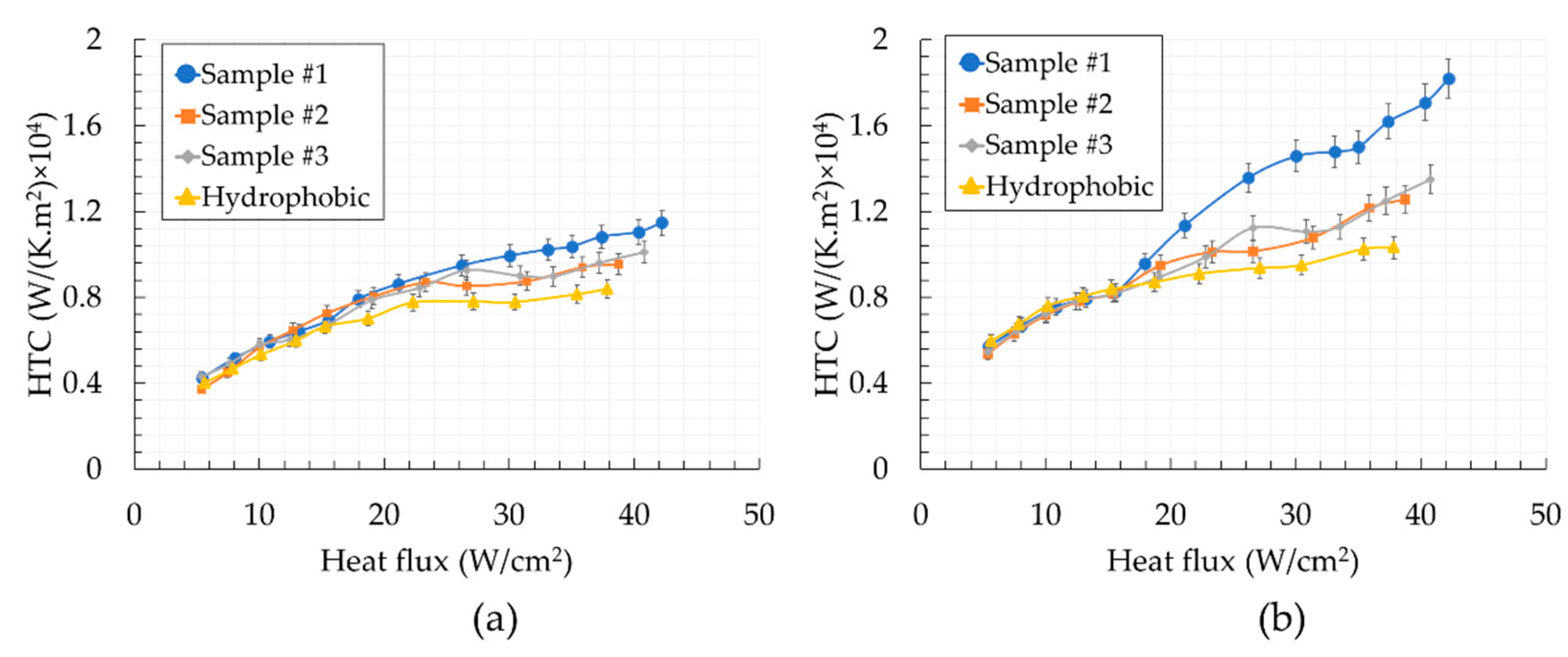
  • Biphilic surfaces offered a better performance than the reference wholly hydrophobic surface (enhancements up to 56.7%).
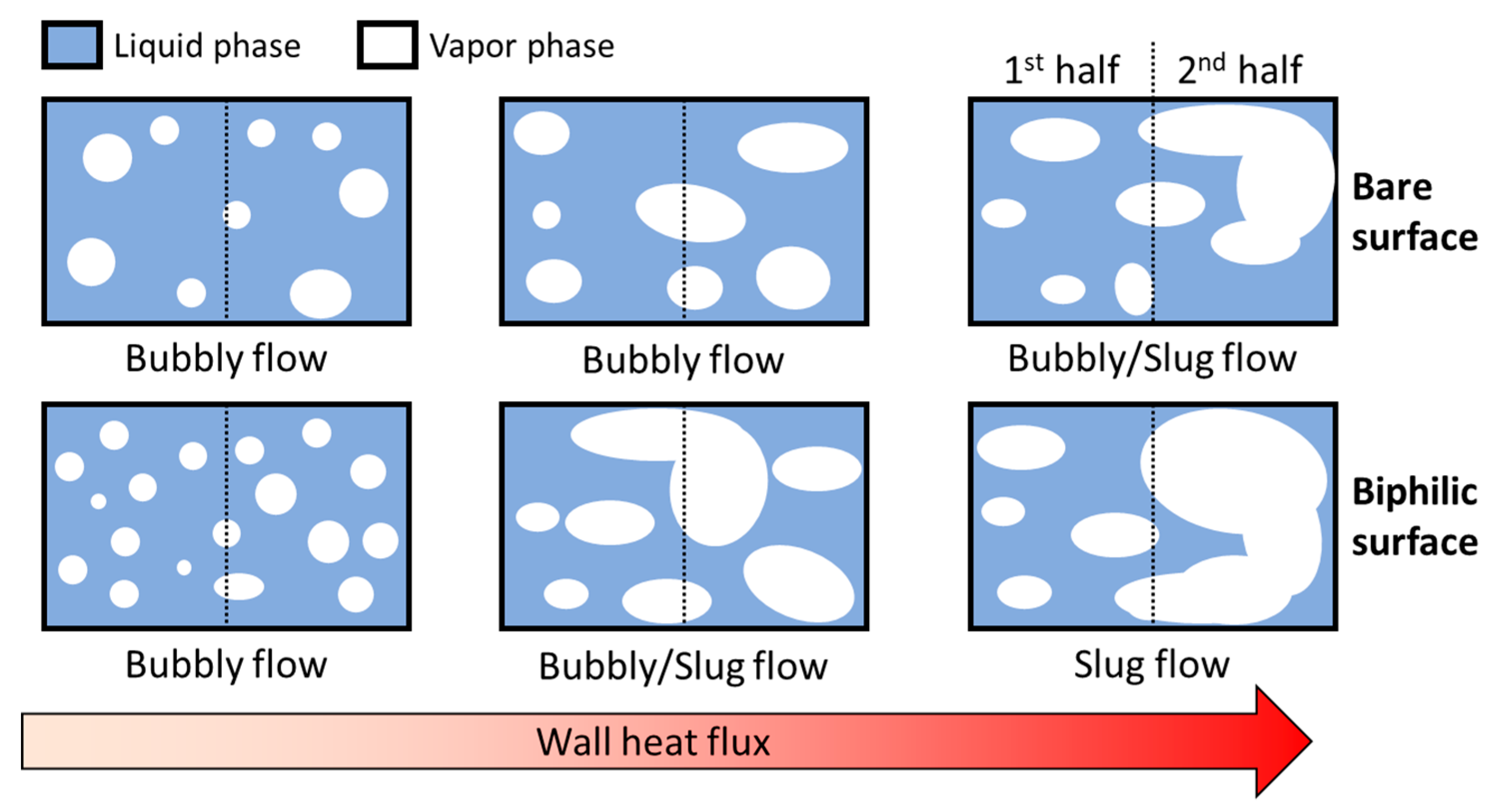
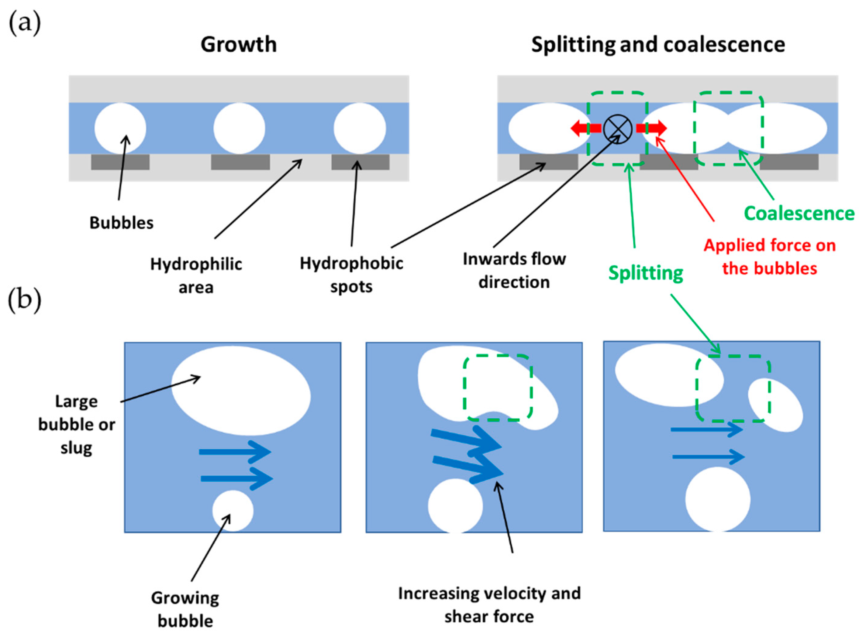
  • Vapor breakup on biphilic surfaces is one of the major mechanisms enhancing flow boiling heat transfer.
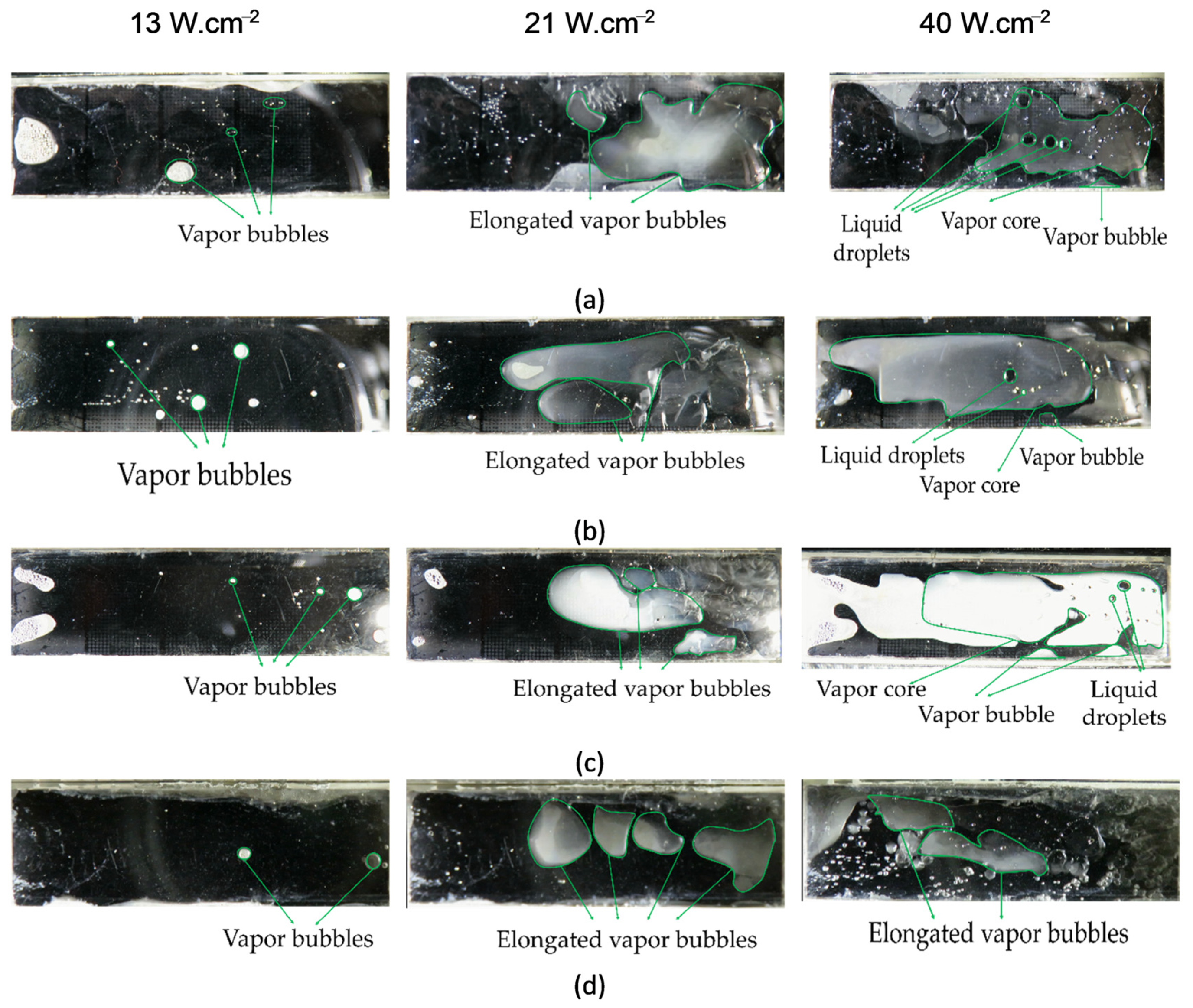
  • All of the biphilic surfaces reduced the length of bubbly flow regime and extended the slug flow regime.
  • The exponential decay in the hydrophobic surface area ratio in the first half of the channel (i.e., sample #1) has a more enhancing effect on heat transfer compared to the exponential decay in the second half of the channel (i.e., sample #3).
  • Surfaces having linear and exponential decay transitions in the second half of the channel have similar heat transfer performances.
The obtained results proved that biphilic surfaces have a great potential for achieving high heat flux cooling.

Author Contributions

Conceptualization, V.E.A., A.A., A.K.S., K.S., and A.K.; investigation, V.E.A. and A.A.; methodology, V.E.A., A.A., and A.K.S.; supervision, K.S. and A.K.; validation, V.E.A., A.A., and A.K.S.; writing (original draft preparation), V.E.A., A.A., A.K.S., and A.K.; writing (review and editing), A.K.S., K.S., and A.K. All authors have read and agreed to the published version of the manuscript.

Funding

This study was funded by the Scientific and Technological Research Council of Turkey (TUBITAK) and Royal Academy of Engineering through the 1601-Bilateral Newton-Katip Çelebi Cooperation Programme-Project number: 4180047.

Acknowledgments

The financial support to graduate students provided by the Faculty of Engineering and Natural Sciences (FENS) of Sabanci University is appreciated.

Conflicts of Interest

The authors declare no conflict of interest.

References

  1. Kim, J.; Lee, J.S. Numerical study on the effects of inertia and wettability on subcooled flow boiling in microchannels. Appl. Therm. Eng. 2019, 152, 175–183. [Google Scholar] [CrossRef]
  2. Frey, S.W., Jr.; Herson, M.I. Natural Convection Cooling System for Electronic Components. Allen Bradley Co LLC. US Patent US4535386A, 13 August 1985. [Google Scholar]
  3. Ahmadi, V.E.; Erden, H.S. Investigation of CRAH Bypass for Air-Cooled Data Centers using Computational Fluid Dynamics. In Proceedings of the 2018 IEEE International Telecommunications Energy Conference (INTELEC), Turin, Italy, 7–11 October 2018; pp. 1–6. [Google Scholar] [CrossRef]
  4. Ahmadi, V.E.; Erden, H.S. A parametric CFD study of computer room air handling bypass in air-cooled data centers. Appl. Therm. Eng. 2020, 166. [Google Scholar] [CrossRef]
  5. Choi, C.; Shin, J.S.; Yu, D.I.; Kim, M.H. Flow boiling behaviors in hydrophilic and hydrophobic microchannels. Exp. Therm. Fluid Sci. 2011, 35, 816–824. [Google Scholar] [CrossRef]
  6. Bottini, J.L.; Kumar, V.; Hammouti, S.; Ruzic, D.; Brooks, C.S. Influence of wettability due to laser-texturing on critical heat flux in vertical flow boiling. Int. J. Heat Mass Transf. 2018, 127, 806–817. [Google Scholar] [CrossRef]
  7. Sadaghiani, A.K.; Koşar, A. Numerical and experimental investigation on the effects of diameter and length on high mass flux subcooled flow boiling in horizontal microtubes. Int. J. Heat Mass Transf. 2016, 92, 824–837. [Google Scholar] [CrossRef]
  8. Sadaghiani, A.K.; Saadi, N.S.; Parapari, S.S.; Karabacak, T.; Keskinoz, M.; Koşar, A. Boiling heat transfer performance enhancement using micro and nano structured surfaces for high heat flux electronics cooling systems. Appl. Therm. Eng. 2017, 127, 484–498. [Google Scholar] [CrossRef]
  9. Kaya, A.; Özdemir, M.R.; Koşar, A. High mass flux flow boiling and critical heat flux in microscale. Int. J. Therm. Sci. 2013, 65, 70–78. [Google Scholar] [CrossRef]
  10. Lin, S.; Sefiane, K.; Christy, J.R.E. Prospects of confined flow boiling in thermal management of microsystems. Appl. Therm. Eng. 2002, 22, 825–837. [Google Scholar] [CrossRef]
  11. Fang, X.; Wang, R.; Chen, W.; Zhang, H.; Ma, C. A review of flow boiling heat transfer of nanofluids. Appl. Therm. Eng. 2015, 91, 1003–1017. [Google Scholar] [CrossRef]
  12. Liang, G.; Mudawar, I. Review of channel flow boiling enhancement by surface modification, and instability suppression schemes. Int. J. Heat Mass Transf. 2020, 146, 118864. [Google Scholar] [CrossRef]
  13. Şişman, Y.; Sadaghiani, A.K.; Khedir, K.R.; Brozak, M.; Karabacak, T.; Koşar, A. Subcooled flow boiling over microstructured plates in rectangular minichannels. Nanoscale Microscale Thermophys. Eng. 2016, 20, 173–190. [Google Scholar] [CrossRef]
  14. Sadaghiani, A.K.; Motezakker, A.R.; Özpınar, A.V.; İnce, G.Ö.; Koşar, A. Pool boiling heat transfer characteristics of inclined pHEMA-coated surfaces. J. Heat Transfer 2017, 139, 111501. [Google Scholar] [CrossRef]
  15. Mathew, J.; Lee, P.-S.; Wu, T.; Yap, C.R. Experimental study of flow boiling in a hybrid microchannel-microgap heat sink. Int. J. Heat Mass Transf. 2019, 135, 1167–1191. [Google Scholar] [CrossRef]
  16. Harirchian, T.; Garimella, S.V. Effects of channel dimension, heat flux, and mass flux on flow boiling regimes in microchannels. Int. J. Multiph. Flow 2009, 35, 349–362. [Google Scholar] [CrossRef] [Green Version]
  17. Tibirica, C.B.; Ribatski, G. Flow patterns and bubble departure fundamental characteristics during flow boiling in microscale channels. Exp. Therm. Fluid Sci. 2014, 59, 152–165. [Google Scholar] [CrossRef]
  18. Wang, G.; Cheng, P. An experimental study of flow boiling instability in a single microchannel. Int. Commun. Heat Mass Transf. 2008, 35, 1229–1234. [Google Scholar] [CrossRef]
  19. Yin, L.; Jia, L. Confined bubble growth and heat transfer characteristics during flow boiling in microchannel. Int. J. Heat Mass Transf. 2016, 98, 114–123. [Google Scholar] [CrossRef]
  20. Alam, T.; Li, W.; Yang, F.; Chang, W.; Li, J.; Wang, Z.; Khan, J.; Li, C. Force analysis and bubble dynamics during flow boiling in silicon nanowire microchannels. Int. J. Heat Mass Transf. 2016, 101, 915–926. [Google Scholar] [CrossRef] [Green Version]
  21. Frost, W.; Kippenhan, C.J. Bubble growth and heat-transfer mechanisms in the forced convection boiling of water containing a surface active agent. Int. J. Heat Mass Transf. 1967, 10, 931–949. [Google Scholar] [CrossRef]
  22. Kandlikar, S.G. Scale effects on flow boiling heat transfer in microchannels: A fundamental perspective. Int. J. Therm. Sci. 2010, 49, 1073–1085. [Google Scholar] [CrossRef]
  23. Kandlikar, S.G. A theoretical model to predict pool boiling CHF incorporating effects of contact angle and orientation. J. Heat Transf. 2001, 123, 1071–1079. [Google Scholar] [CrossRef]
  24. Hsu, C.-C.; Chen, P.-H. Surface wettability effects on critical heat flux of boiling heat transfer using nanoparticle coatings. Int. J. Heat Mass Transf. 2012, 55, 3713–3719. [Google Scholar] [CrossRef]
  25. Li, Y.-Y.; Liu, Z.-H.; Wang, G.-S. A predictive model of nucleate pool boiling on heated hydrophilic surfaces. Int. J. Heat Mass Transf. 2013, 65, 789–797. [Google Scholar] [CrossRef]
  26. Zhou, K.; Coyle, C.; Li, J.; Buongiorno, J.; Li, W. Flow boiling in vertical narrow microchannels of different surface wettability characteristics. Int. J. Heat Mass Transf. 2017, 109, 103–114. [Google Scholar] [CrossRef] [Green Version]
  27. Searle, M.; Emerson, P.; Crockett, J.; Maynes, D. Influence of microstructure geometry on pool boiling at superhydrophobic surfaces. Int. J. Heat Mass Transf. 2018, 127, 772–783. [Google Scholar] [CrossRef]
  28. Betz, A.R.; Jenkins, J.; Kim, C.J.; Attinger, D. Boiling heat transfer on superhydrophilic, superhydrophobic, and superbiphilic surfaces. Int. J. Heat Mass Transf. 2013, 57, 733–741. [Google Scholar] [CrossRef] [Green Version]
  29. Motezakker, A.R.; Sadaghiani, A.K.; Çelik, S.; Larsen, T.; Villanueva, L.G.; Koşar, A. Optimum ratio of hydrophobic to hydrophilic areas of biphilic surfaces in thermal fluid systems involving boiling. Int. J. Heat Mass Transf. 2019, 135, 164–174. [Google Scholar] [CrossRef]
  30. Yamada, M.; Shen, B.; Imamura, T.; Hidaka, S.; Kohno, M.; Takahashi, K.; Takata, Y. Enhancement of boiling heat transfer under sub-atmospheric pressures using biphilic surfaces. Int. J. Heat Mass Transf. 2017, 115, 753–762. [Google Scholar] [CrossRef]
  31. Zupančič, M.; Steinbücher, M.; Gregorčič, P.; Golobič, I. Enhanced pool-boiling heat transfer on laser-made hydrophobic/superhydrophilic polydimethylsiloxane-silica patterned surfaces. Appl. Therm. Eng. 2015, 91, 288–297. [Google Scholar] [CrossRef] [Green Version]
  32. Aboubakri, A.; Yanik, C.; Akkuş, Y.; Koşar, A.; Sadaghiani, A.K. Numerical and Experimental Investigation on Evaporation of Water Droplet on Surfaces with Mixed Wettability. In Proceedings of the ASME 2020 18th International Conference on Nanochannels, Microchannels, and Minichannels Collocated with the ASME 2020 Heat Transfer Summer Conference and the ASME 2020 Fluids Engineering Division Summer Meeting, 13–15 July 2020; American Society of Mechanical Engineers Digital Collection: New York, NY, USA, 2020. [Google Scholar]
  33. Gong, S.; Cheng, P. Numerical simulation of pool boiling heat transfer on smooth surfaces with mixed wettability by lattice Boltzmann method. Int. J. Heat Mass Transf. 2015, 80, 206–216. [Google Scholar] [CrossRef]
  34. Coleman, H.W.; Steele, W.G. Experimentation, Validation, and Uncertainty Analysis for Engineers; John Wiley & Sons: Hoboken, NJ, USA, 2018. [Google Scholar]
  35. Shah, R.K.; London, A.L. Laminar Flow Forced Convection in Ducts: A Source Book for Compact Heat Exchanger Analytical Data; Academic Press: Cambridge, MA, USA, 2014. [Google Scholar]
  36. Sun, L.; Mo, Z.; Zhao, L.; Liu, H.; Guo, X.; Ju, X.; Bao, J. Characteristics and mechanism of bubble breakup in a bubble generator developed for a small TMSR. Ann. Nucl. Energy 2017, 109, 69–81. [Google Scholar] [CrossRef]
  37. Sadaghiani, A.K.; Altay, R.; Noh, H.; Kwak, H.J.; Şendur, K.; Mısırlıoğlu, B.; Park, H.S.; Koşar, A. Effects of bubble coalescence on pool boiling heat transfer and critical heat flux—A parametric study based on artificial cavity geometry and surface wettability. Int. J. Heat Mass Transf. 2020, 147, 1–15. [Google Scholar] [CrossRef]
Figure 1. Schematic of the (a) experimental setup (b) test section (c) of thermocouple locations and approach to find the substrate temperature.
Fluids 05 00239 g001
Figure 2. (a) Fabrication process flow (b) Microscopic view of fabricated patterns (c) Image of sample #2.
Fluids 05 00239 g002
Figure 3. Schematic view of designed patterns.
Fluids 05 00239 g003
Figure 4. Validation of experimental results.
Fluids 05 00239 g004
Figure 5. Obtained heat transfer coefficients for mass flux of 40 kg m−2s−1 (a) for the 1st half of the microchannel (b) for the 2nd half of the microchannel.
Fluids 05 00239 g005
Figure 6. Obtained heat transfer coefficients for mass flux of 80 kg m−2s−1 (a) the 1st half of the microchannel (b) the 2nd half of the microchannel.
Fluids 05 00239 g006
Figure 7. Schematic of flow map transition on biphilic surfaces.
Fluids 05 00239 g007
Figure 8. Obtained heat transfer coefficients for mass flux of 120 kg m−2s−1 (a) the 1st half of the microchannel (b) the 2nd half of the microchannel.
Fluids 05 00239 g008
Figure 9. Schematic of the (a) bubble breakup in the stream (b) bubble coalescence and splitting in the biphilic surfaces.
Fluids 05 00239 g009
Figure 10. Flow patterns on tested sample at three different heat fluxes (a) sample #1, (b) sample #2, (c) sample #3 and (d) wholly hydrophobic surface.
Fluids 05 00239 g010
Table 1. Uncertainties in the experimental parameters.
ParametersUncertainty
Voltage±1 V
Current±0.01 A
Wall temperature ±0.3 K
Mass flow rate±2–5%
Channel dimensions±15 μm
Heat transfer coefficient±4.5–7.5%
Table 2. Summarized properties of fabricated surfaces.
Surface A * D   of   Region   II A * D   of   Region   III A * D   of   Region   IV
Sample #175%-500 µm67%-475 µm50%-400 µm
Sample #275%-500 µm50%-400 µm25%-300 µm
Sample #350%-400 µm25%-300 µm12%-200 µm
Publisher’s Note: MDPI stays neutral with regard to jurisdictional claims in published maps and institutional affiliations.

