1. Introduction
Rotary kilns are long cylindrical furnaces [
1]. They are widely employed by the material processing industry to manufacture, e.g., cement or zinc-oxide, to treat waste or to recycle materials such as bitumen.
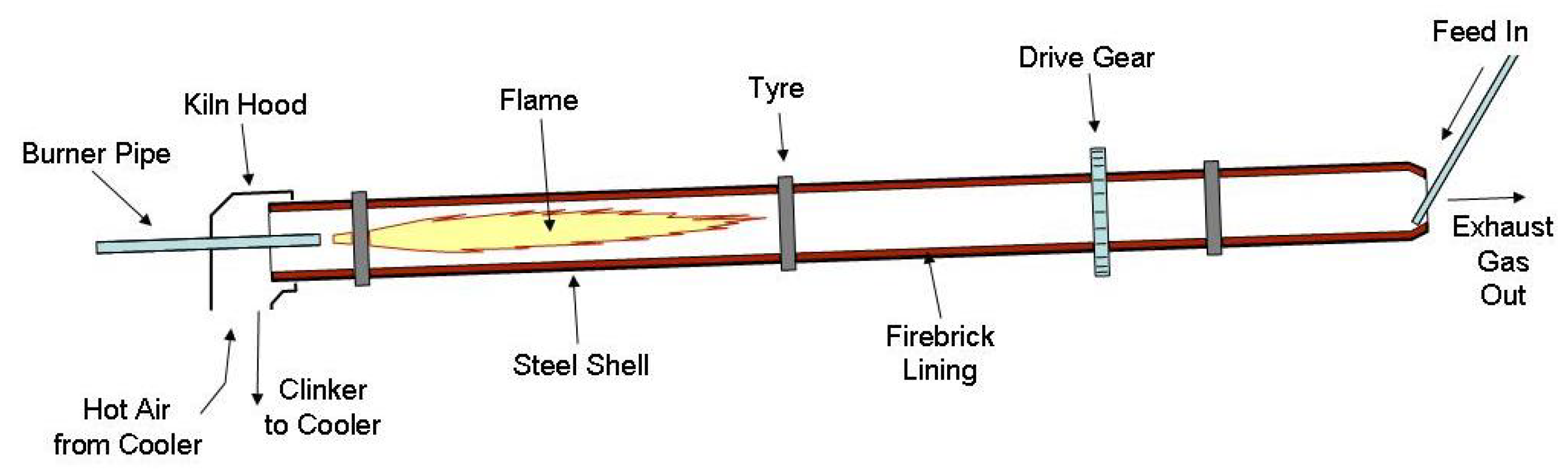
We target a direct-fired counter-current flow rotary kiln in which the temperature reaches levels above 1800 degrees Kelvin. The kiln is placed horizontally with a slight inclination, as shown schematically in
Figure 1. The raw material is fed from top end. It is forced to travel through the kiln by the rotary motion around its main axis. A burner producing a flame is installed at the low end the kiln. The material bed is mixed, heated and subjected to sintering reactions. The material leaves the furnace at the low end to be further processed. Sufficiently high temperatures are required to heat the material to reach the sintering reactions. This makes the process prone to the formation of thermal nitric-oxides (NOx).
The numerical simulation of rotary kilns is important to obtain insight into the heat generation by the flame and transfer to the material bed. This understanding is vital to reduce off-spec production, fuel consumption and pollutant emission. In-situ experimental campaigns are hampered by high temperatures and harsh operating conditions. The combustion and material processing in rotary kilns has therefore been been studied extensively using both numerical simulations and lab-scale experiments. A recent survey is given in the PhD thesis by Pedersen [
2].
The combustion in the cement clinker kiln that we consider is fed by a non-premixed turbulent flow of methane and air. The combustion air is separated into a primary and secondary air flow. The primary air and methane enter the kiln via the burner pipe. At the end of the burner pipe, a burner injects the methane and the primary air into the freeboard of the kiln. The burner consists of small nozzles that are mounted with either an axial or outwardly inclined orientation. These nozzles inject methane jets with high momentum. The nozzles are surrounded by a circular slot through which the primary air passes with lower momentum. During operation, the mixture of methane and air ignites and gives raise to a short and intense flame. The burner pipe is prevented from overheating by the flow of the primary air. Secondary air is blown into the kiln in co-flow with the fuel jets and primary air stream. This secondary air is entrained by the jets leaving the burner. This entrainment spurs the growth of the flame. A long and low burning (so-called
lazy) diffusion flame with thin reaction fronts is formed. Representative images of the burner, burner pipe and flame are shown, e.g., in the recent PhD thesis byPedersen [
2] and on the website of rotary kiln manufacturers such as FLSmith and Feeco. We refer to the mixed jets of the fuel and the primary combustion air as the primary jet. In the following three paragraphs, we review literature on non-reactive flow, turbulent combustion and thermal NOx formation in rotary kilns, respectively.
Early publications recognize that combustion in rotary kilns is mainly driven by the turbulent mixing of the primary jet and the secondary air [
2]. The importance of mixing has given rise to a body of literature on the aerodynamics in rotary kilns. In this early literature, the effect of combustion is taken into account by considering the decrease of density of the primary jet due to heat release. The jet mixing, the entrainment of the secondary jet into the primary, the formation of recirculation zones and the length of the flame can be expressed in terms of the Craya–Curtet similarity parameter. This parameter is defined as the square root of the ratio of the momentum of the primary to the secondary jet. Representative values for the parameter for cement kilns are listed in [
1]. The simplifying assumptions that allow the definition of a Craya–Curtet parameter, however, do not apply to the kiln configurations studied in this paper. More detailed CFD models, as developed in [
3], are therefore required. This paper shows that the co-flow of jets at different velocities result in shear layers in which vortices are created. These vortices shed further downstream at a characteristic frequency. These vortices are studied experimentally for planar jets in [
4]. The frequency of the vortex shedding has been determined for the non-reactive flow in a down-scaled rotary kiln both numerically and experimentally ([
3] and references therein). The same authors discussed to what extent the non-stationary flow in the kiln can be approximated by stationary flow models.
The combustion in rotary kilns has been studied in various pilot-scale laboratory set-ups. The influence of the ratio of amount of primary and secondary air on the flame shape was investigated experimentally, e.g., by Mohanan et al. [
5]. The analysis shows that a small amount of primary air ignites the mixture. The heat released by the combustion increases the momentum of the primary jet. The length of the flame increases with the amount of secondary air. The radiative heat transfer in kilns has been studied experimentally in [
6].
The cement production process requires temperatures of the freeboard gasses well above 1800 K. These elevated temperatures render the process very sensitive to the formation of thermal NOx. Various counter measures have therefore been developed. These include the design of low NOx swirl burners, catalytic reduction techniques and systems that enrich the oxidizer with oxygen. A recent overview for iron-ore rotary kilns is given in [
7]. The numerical simulation is deemed to be vital to render these counter measures even more effective. In this paper, we model the formation of thermal NOx using the Zel’dovich mechanism in the post-processing stage of reactive flow simulations. More information on measures to mitigate NOx formation can by found elsewhere (e.g., [
8,
9]).
In this work, we study the non-premixed turbulent combustion in the full-scale cement rotary kiln that we considered earlier in [
10]. In this earlier work, simulations were performed using a commercial CFD package. Our goal here is to perform more comprehensive and detailed simulations using OpenFoam [
11]. Our aim is to study how the thermal NOx formation is influenced by the shape of the secondary air inlet channel. We wish to compare the rectangular secondary air inlet with an annular one placed concentrically with the burner pipe. The annular configuration is expected to distribute the air evenly over the flame, result in evenly distributed reaction front and lower peak temperatures and therefore the formation of thermal NOx.
This paper is structured in nine sections. In
Section 2, we describe the mathematical model for the turbulent non-premixed combustion in the rotary kiln that we solve. In
Section 3, we describe tools available in OpenFoam to model this combustion process. In
Section 4, we describe how these tools are used to model the combustion in the rotary kiln. In
Section 5, we describe the mesh generation process using cfMesh. In
Section 6,
Section 7 and
Section 8, we present simulation results for the non-reactive flow, the reactive flow and the thermal NOx formation in the kiln. In
Section 9, we draw conclusions.
2. Mathematical Model
In this section, we describe the mathematical model for combustion in the kiln. The model consists of the following four components: a model for the combustion of methane in the freeboard of the kiln including radiative heat transfer, a model for the conductive heat transfer in the lining, a model for the interface between the freeboard and the lining and a model for the thermal NOx formation in the freeboard. In the following four subsections, these components are described individually. Details on the fluid flow, combustion, radiative heat transfer and conjugate heat transfer components of the model can be found elsewhere (see, e.g., [
12,
13,
14,
15,
16,
17,
18,
19,
20], respectively).
2.1. Model for Combustion of Methane in the Freeboard
The mixture of gaseous fuel, primary and secondary combustion air and combustion products is modeled as a mixture of ideal gasses. Properties such as density , heat capacity , molecular viscosity and thermal conductivity of this mixture are expressed in terms of weighted averages. The turbulent flow of this gas in the kiln is described using the Favre-averaged (or density-weighed Reynolds-Averaged) Navier–Stokes equations with the realizable k-epsilon model for the turbulent kinetic energy k and turbulent dissipation rate for the turbulence closure. The flow through the burner nozzles occurs at a high speed. The Mach number reaches the value of approximately 0.8–0.9 in proximity to the burner. The incompressible flow formulation is therefore no longer valid. A compressible formulation in which energy is formulated in terms of the enthalpy h and in which the thermodynamical properties are based on the density is adopted.
The chemistry of the combustion involves a number of chemical species indexed by
ℓ and a number of reaction steps indexed by
s. The mass fraction
of the
ℓth species is governed by a convection-diffusion-reaction equation with source term
. We assume that a single diffusion coefficient denoted by
D can be used for all species and that the Lewis number can be set equal to one. The expression for reaction mechanism is specified by the combustion model. Here, the eddy-dissipation combustion model for methane with a single step reaction mechanism
is chosen. The choice for fast chemistry is motivated by the high Damkohler number that governs the combustion. The Damkohler number
is defined as
, where
and
are the time scales for the flow and the chemistry, respectively.
Let
,
p and
T denote the velocity vector of the gas, the pressure and the temperature in the kiln, respectively. The enthalpy is the sum of the sensible enthalpy and the formation enthalpy of the mixture, i.e.,
where
is a reference temperature and
is the enthalpy of formation of the
ℓth species. To avoid the computational expense of transient simulations, we resort to stationary approximations of the flow conditions despite the transient nature of the flow. The conservation of mass, momentum and energy of the mixture and the conservation of the species
can then be expressed as
where
in the right-hand side of (
5) denotes the source term due to radiative transport of heat. This term is discussed in more detail in the next paragraph. The system of conservation equations is closed by ideal gas law. The viscosity
is the sum of the laminar viscosity
and turbulent viscosity
. The latter is expressed in term of the turbulent quantities
k and
as
where the model constant
depends on the mean strain and rotation rate in the realizable k-epsilon turbulence model adopted. Inflow conditions are specified in terms of mass flow rates. The pressure is prescribed on the outlet. Standard wall functions for the turbulent kinetic energy
k, turbulent dissipation
and turbulent viscosity
are applied. The boundary condition for the temperature is given by an interface condition of the interface between the freeboard and the lining.
The freeboard gasses are assumed to be gray (or frequency-independent) for the radiative transport of heat. This transport is modeled by a discrete ordinate method. The choice is motivated by the ability to use various numbers of rays to estimate the error made in modeling the radiative transport. The space is discretized in various angular directions
. In each direction, a transport equation for the radiative intensity
is solved. This intensity depends on the position vector
and the direction
. The black body intensity
acts as a source term in this equation. We neglect the effect of scattering by soot in the radiative heat transfer given the high air–fuel ratio. Only emission and absorption of intensity therefore play a role. The effect of soot was omitted due to the high air–fuel ratio in the flame. The absorption coefficient
is modeled using a weighted sum of gray gasses (WSGG) model. The radiative transport equation can then be written as
The wall emissivity
is taken into account in the boundary condition for
as
where
is the incident intensity and
are weights for the angular integration. Having solved for the individual rays, the radiative heat source
in the energy Equation (
5) can be expressed as
2.2. Model for Heat Conduction in the Lining
The combustion model of the freeboard gasses is coupled with a model that describes heat transfer by conduction in the refractory lining surrounding the freeboard. Heat is allowed to transfer to the exterior surrounding by prescribing a boundary condition for the radiative heat on the interface between the lining and the exterior.
2.3. Conditions on the Freeboard-Lining Interface
This coupling is realized by imposing the continuity of the temperature and the heat flux on the interface separating the freeboard and the lining. In the freeboard domain, the heat flux has a conductive, convective and radiative component, while, in the lining domain, it has a conductive component only.
The refractory lining absorbs the heat produced by the flame. This absorption causes the peak temperature in the flame to change. We modeled this effect in [
21]. The change of peak temperature is important to consider in the modeling of thermal NOx formation. In practice, the presence of the material bed is expected to further redistribute the heat in the kiln. In this paper, however, the presence of the material bed is not taken into consideration. In future work, the presence of the material bed can be modeled by, for instance, changing the thermal properties of the lining.
2.4. Model for the Thermal NOx Formation in the Freeboard
The mathematical model that we thus obtain expresses the conservation equation for mass, momentum, enthalpy and chemical species. Having solved the model, we compute the thermal NOx concentration using the extended Zel’dovich mechanism with three reactions and seven species (H, N, N
, NO, O, O
and OH) in the post-processing stage (see, e.g., Section 12.28 in [
12]). This work employs the implementation of this model in OpenFoam realized in the master thesis by Kadar [
22]. This implementation employs equilibrium chemistry to compute the mass fraction of the species O and OH [
23].
We perform mesh generation using cfMesh. We verify our non-reactive flow computations using IB-Raptor. IB-Raptor is the immersed boundary finite volume solver for the compressible Navier–Stokes developed by PMSQUARED Engineering [
24]. It uses an approximate Riemann method to compute the fluxes and a symmetric Gauss-Seidel LU method to advance the solution in time. In the current state of development, IB-Raptor does not allow the simulation of reactive flow. To validate the reactive flow computations, we therefore compare with our previous results in [
10].
3. Combustion Processes in OpenFOAM
In this section, we describe recent progress in the modeling of turbulent non-premixed combustion using OpenFoam. We restrict our attention to the modeling of diffusion flames arising for burning methane in industrial furnaces. In this context, the term ‘combustion processes’ encompasses the turbulent reactive flow of fuel and oxidizer in the freeboard, the heat transfer by radiation and the conjugate heat transfer in the refractory lining. This section serves as a basis for further elaboration in the remainder of the paper.
The modeling of non-premixed combustion, radiative heat transfer and conjugate heat transfer in OpenFOAM has recently attracted considerable attention. Examples of the development of OpenFoam-based solvers based on the flamelet generated manifold concept are found in [
25,
26] (and references cited therein). Solvers based on the alternative eddy-dissipation concept are developed in [
27,
28]. The implementation of detailed models for radiative heat transfer is considered in [
29,
30]. The combination of combustion in the fluid domain and conjugate heat transfer in the solid domain was pursued, e.g., by the authors of [
31,
32,
33].
4. Rotary Kiln in OpenFOAM
In this section, we describe tools available in OpenFoam to implement the non-reactive and reactive flow model in the kiln as well as the thermal NOx post-processor.
The non-reactive turbulent compressible flow in the kiln is simulated in stationary regime using rhoSimpleFoam. This solver adds thermodynamics to the aerodynamics implemented in the incompressible solver simpleFoam. The system expressing conservation of mass and momentum is augmented with an equation for energy. The augmented system is closed by an equation of state. Here, the ideal gas law is used. A formulation in terms of the density
is adopted. In this formulation, the pressure is an explicit function of the density. In the alternative formulation based on the compressibility
, the pressure depends implicitly on the density via the compressibility. The equations for pressure, velocity, turbulent quantities and energy are solved segregated using the SIMPLE algorithm. Details of a compressible solver similar to rhoSimpleFoam are given in Chapter 16 of [
13]. The vortex shedding in the shear layer between the fuel jets and the coflow of air renders the flow non-stationary. We approximate this non-stationary behavior by running a stationary solver for a large number of iterations. The use of a steady state RANS approximation to study flows with vortex shedding was discussed by Iaccarino et al. [
34]. The convergence of rhoSimpleFoam was initially hampered by the complexity of the flow pattern. We therefore extended the computational domain by attaching a large cube to the outlet path of the cylindrical domain. The side of the cube extends several kiln diameters. In this way, the outlet patch is moved further downstream and outflow boundary conditions no longer obstruct the flow. The flow field continues to change on a macroscopic level even after a small residual norm has been reached. Further research is required to describe conditions in which the additional cube on the outflow of the kiln is indispensable to obtain convergence of the flow solver.
The turbulent compressible reactive flow in the kiln is simulated in a stationary regime using multiRegionReactingFoam [
35] with basic thermodynamical properties based on compressibility.
The thermal NOx post-processor is taken from the master thesis by Kadar [
22]. Throughout this paper, OpenFoam-v1906 is used.
5. Mesh Generation
We perform mesh generation using cfMesh. cfMesh is a collection of mesh generation tools distributed as a library [
36]. This library is designed to provide customizable meshing workflows for automatic generation of meshes with various cell types in complex geometries of industrial interest. cfMesh generates hex-dominant meshes, tetrahedral meshes, meshes consisting of arbitrary polyhedra and 2D quad-dominant meshes. The library uses both shared-memory with OpenMP and distributed-memory parallelization with MPI. Parallelization is encapsulated inside the meshing algorithms. Hence, it allows customization of the meshing process while preserving the benefits of the code executing in parallel.
The meshing process is controlled by a geometry file given as a surface triangulation, most often as an STL file, and a dictionary containing the parameters provided by the user. Once the geometry and the settings are given, the mesher generates the mesh automatically without any user intervention. The dictionary allows the user to specify the global cell size in the domain and local refinement zones. The latter can be specified via subsets, surface meshes and edges mesh, as well as via objects such as cylinders, boxes, spheres and lines. The dictionary also allows the control of the number of boundary layers at each boundary of the domain, their number and their thickness ratio. Dictionary settings allow mesh-sensitivity studies by changing a single parameter. The algorithms used by cfMesh are described in [
36].
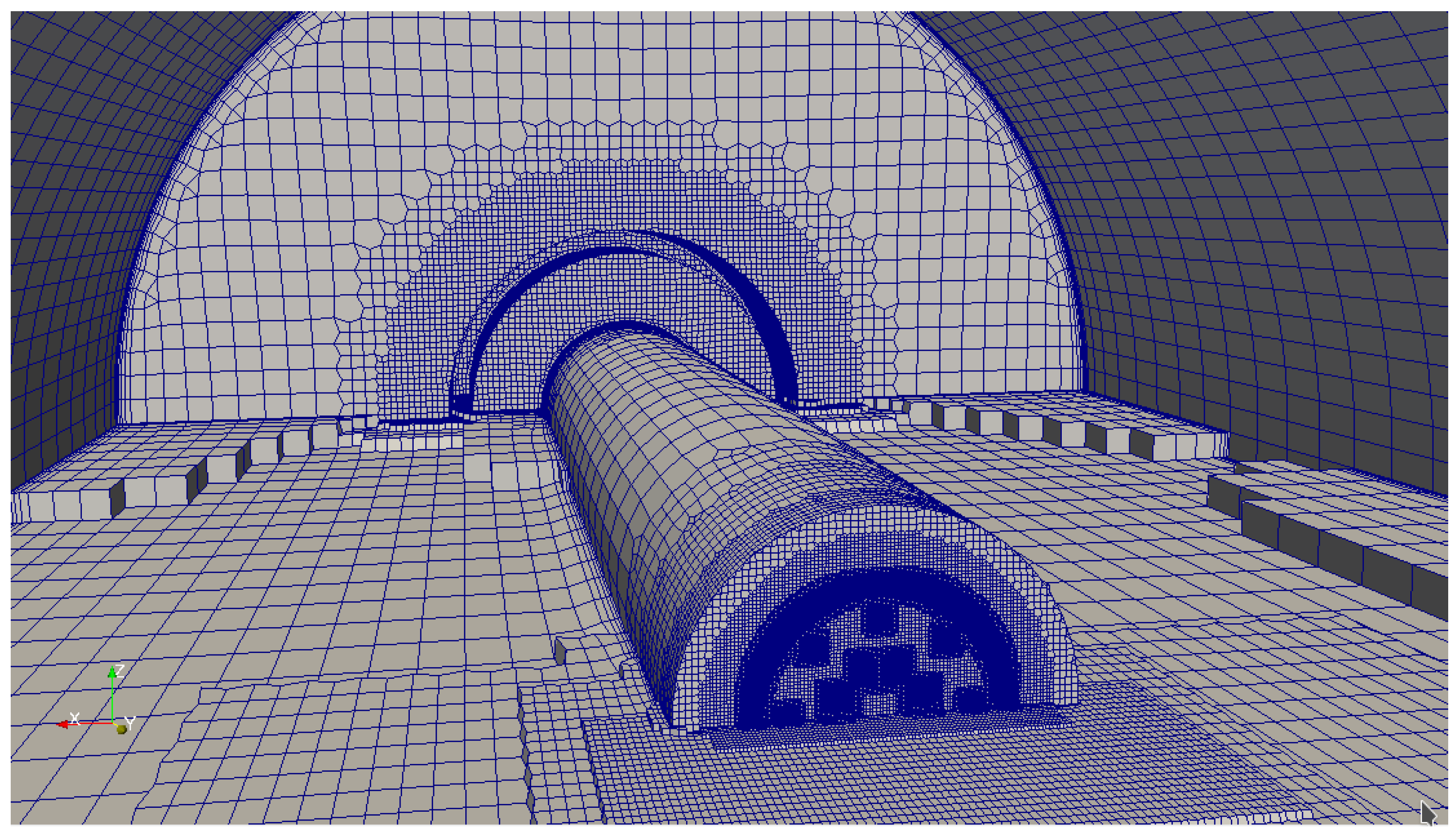
Figure 2 shows the mesh generated for two kiln geometries. In future work, we intend to further investigate to what extent these meshes satisfy the yplus criterium near the wall.
6. Non-Reactive Flow Results
In this section, we discuss simulation results for the non-reactive turbulent flow in the freeboard of the kiln. We consider the case of the rectangular secondary air inlet only. Non-isothermal effects are included by imposing the secondary combustion air temperature to be equal to 773 degrees Kelvin. The fuel and primary combustion air are kept at room temperature at their respective inlets. The flow consists of two features. The first feature is the mixing of the fuel jets and the primary air leaving the burner. The second feature is the backward facing step-like flow caused by the stream of secondary air. Both features interact and give rise to complex non-stationary flow patterns. We ran twenty thousand iterations of rhoSimpleFoam on a mesh consisting of approximately 2.8 million cells. Our goal in this section is to verify the answer provided by rhoSimpleFoam by comparing with IB-Raptor and results provided in the literature. This endeavor is justified by the fact that the combustion is mainly driven by the turbulent mixing of the fuel jets and air streams.
The comparison of the results generated by rhoSimpleFoam and IB-Raptor is hampered by three facts. The first is that the codes use entirely different numerics. The second is that the 2D snapshots of the flow that we show fail to capture three-dimensional flow phenomena. Care is required to give a physical interpretation to these 2D visualizations. The third is that vortices appear in the shear layers of the interaction of the fuel jets, the primary and secondary air stream. These vortices are transported by the flow and shed further downstream. The flow is thus non-stationary. The solution obtained by both codes continue to vary after convergence has been reached. We only present snapshots of the flow. It is however impossible to identify to which of the iteration indices the two codes should be compared. In future work, a more detailed comparison could by carried out by comparing, e.g., the frequency of the vortex shedding computed by both codes, as suggested, e.g., in [
3,
37]. These papers also discuss how the eddy viscosity ratio is overestimated due to an overestimation of the turbulent kinetic energy. In the remainder of this section, we therefore show results for the axial velocity component
and the eddy viscosity
computed using rhoSimpleFoam and IB-Raptor.
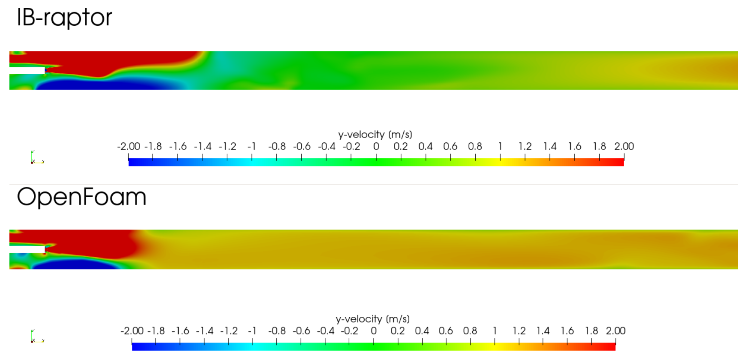
The axial velocity
computed by IB-Raptor and rhoSimpleFoam is shown at the top and bottom of
Figure 3, respectively. For illustration purposes, the velocity component was clipped to the range from
to
. Both codes capture the jet leaving the burner and the recirculation vortex underneath the burner pipe caused by the stream of secondary air. Apparent differences can be observed in the length of the primary jet, the entrainment of the secondary air by the primary jet, the length of the recirculation vortex underneath the burner pipe and the magnitude of the velocity at the center of the kiln. These differences are attributed to the aforementioned difficulties in comparing both codes.
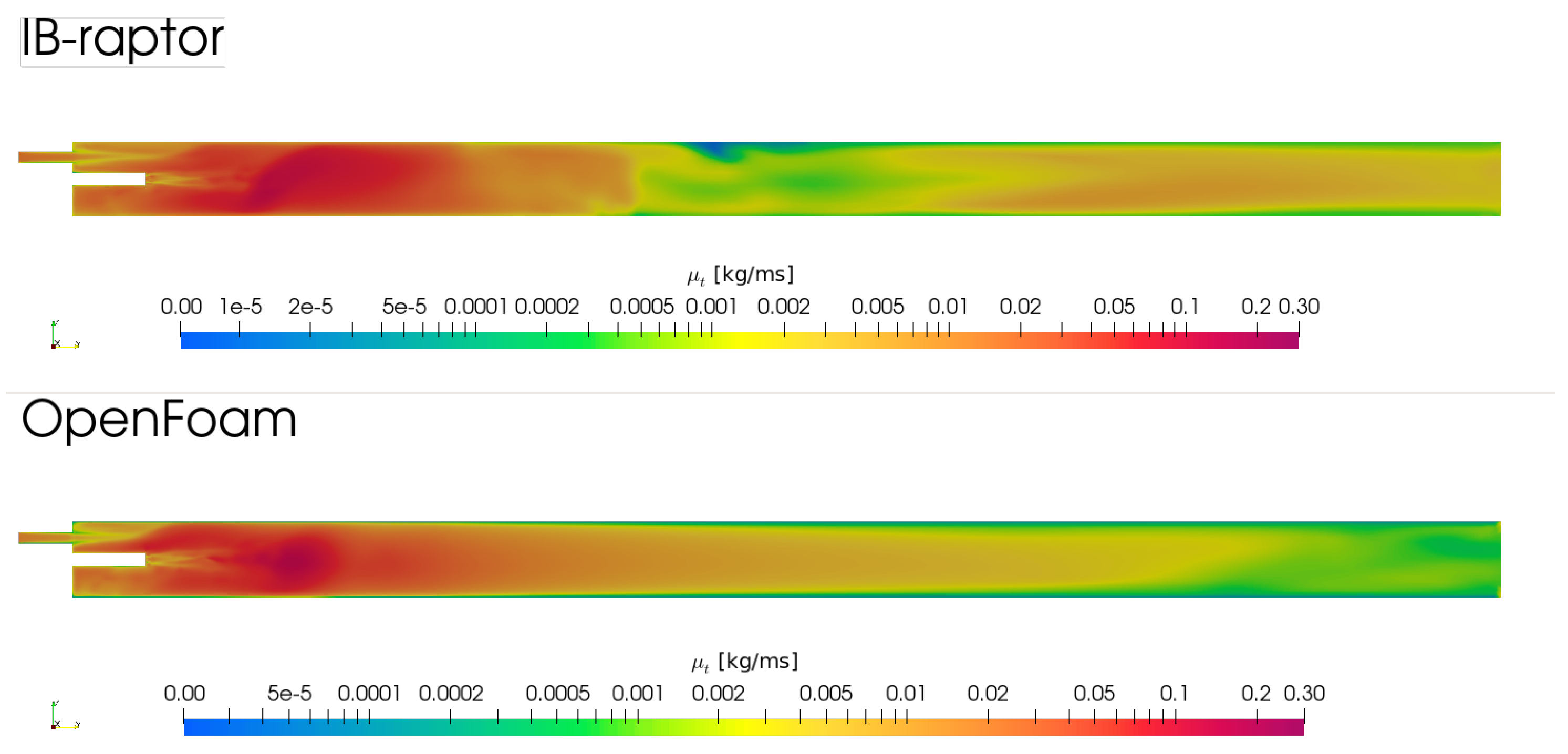
The eddy viscosity
computed by IB-Raptor and rhoSimpleFoam is shown at the top and the bottom of
Figure 4, respectively. Both codes capture large values with comparable magnitude near the burner and decreasing values towards the outlet. For rhoSimpleFoam, this decrease is monotonic, whereas it is not for IB-Raptor. More interestingly, both codes predict an eddy viscosity that remains large for a large distance downstream from the burner. This compares favorably with results in [
3]. Larsson et al. [
3] discussed how the two-equations turbulence model used in these simulations systematically overpredict the turbulent kinetic energy in regions of large strain. This entails an overprediction of the eddy viscosity and therefore a spurious damping of the oscillating motion of the flow. Compared to more advanced turbulence models, the primary jet and secondary stream travel further downstream before merging completely.
7. Reactive Flow Results
In this section, we present the results of the reactive flow simulation in the kiln. We allow the fuel and air to mix and produce a flame. We use a volumetric air–fuel ratio equal to nine throughout this and the next section. Compared to the non-reactive simulation considered in the previous section, the primary jet is hotter, therefore lighter, and has thus more momentum at equal mass inflow rates. The change in balance of momentum contained in the primary and secondary jets significantly alters the parameters and thus the flow characteristics in the kiln. We consider the flame-wall interaction by modeling heat transfer via radiation, convection and conduction. We run 50k iterations of multiRegionReactingFoam [
35] on a mesh consisting of approximately 4.2 million and 4.4 million cells for the configuration with rectangular and annular air inlet, respectively. Our goal is to validate the results of multiRegionReactingFoam for the velocity and heat distribution in the kiln. We compare the use of the rectangular and annular secondary air inlet configuration. In the remainder of this section we first compare the velocity of the primary jet in the non-reactive and reactive simulation. We subsequently compare results for the streamlines and the temperature with results in the literature. We in particular compare with earlier results obtained using commercial software published in [
10].
The burner design determines the shape of the flame. This design is influenced by factors such as the number, location and orientation of the nozzles. The importance of the burner design motivates a closer look into the aerodynamics close to the burner.
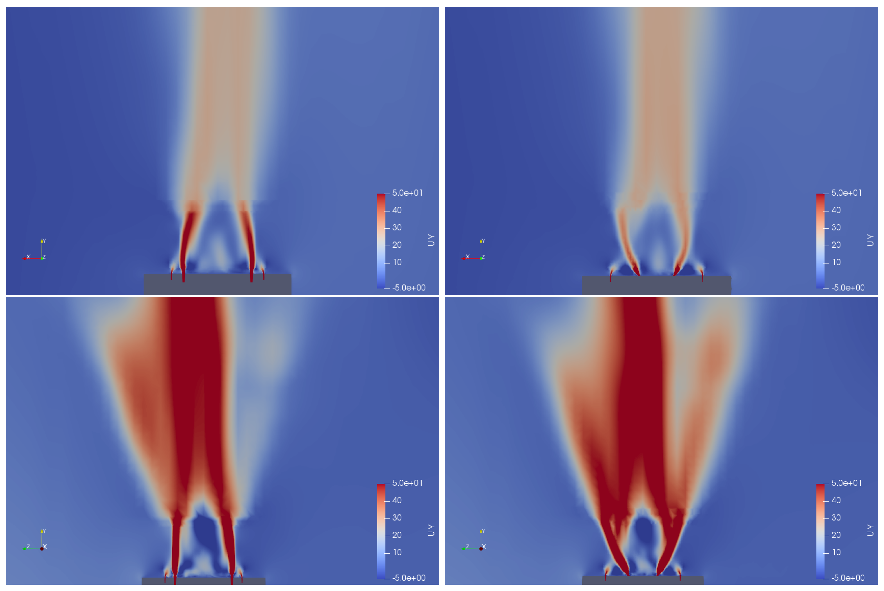
Figure 5 therefore shows the axial component (
y-component) of the velocity of the primary jet on an axial section close to and downstream of the burner. The figure compares the non-reactive flow at the top and reactive flow at the bottom. The two subfigures on the left and the right show the jet leaving the axial and outwardly inclined fuel nozzles, respectively. The fuel jet from the axial nozzle moves towards the centerline while the jet leaving the inclined nozzles travels in the axial direction. The large increase in velocity due to the heat release can clearly be seen. The combustion of fuel jets and air similar to the configuration studied here has been extensively studied in the literature (e.g., [
38]).
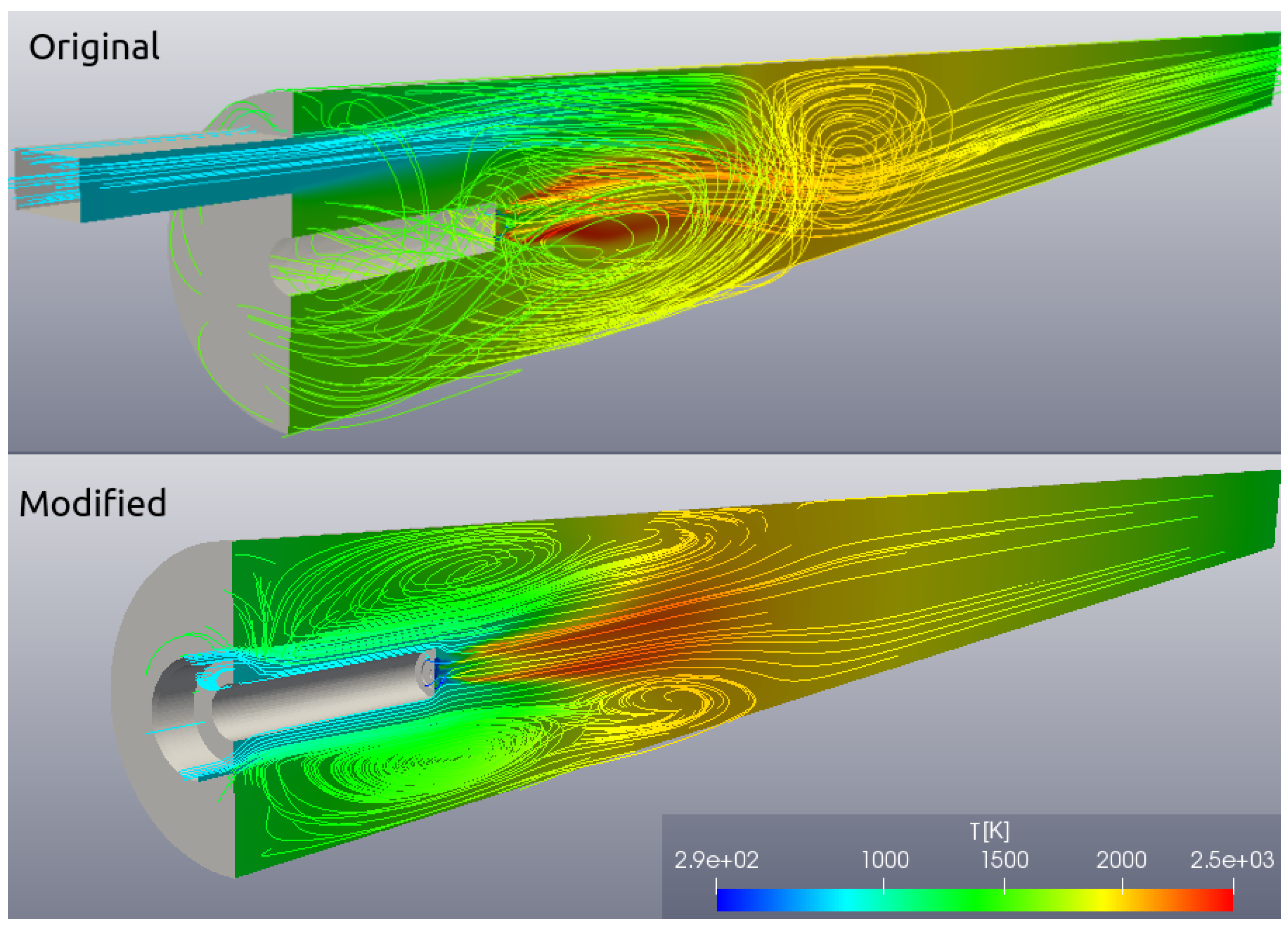
Figure 6 shows the computed stream for the original rectangular (top) and modified annular (bottom) secondary air inlet. Different recirculation patterns can clearly be seen. In the case of the rectangular air inlet, the recirculation vortex underneath the burner pipe supplies the flame with a hot mixture of products and oxidants. This mechanism ensures the stabilization of the flame. In the case of the annular air inlet, the recirculation vortex encircles the burner pipe.
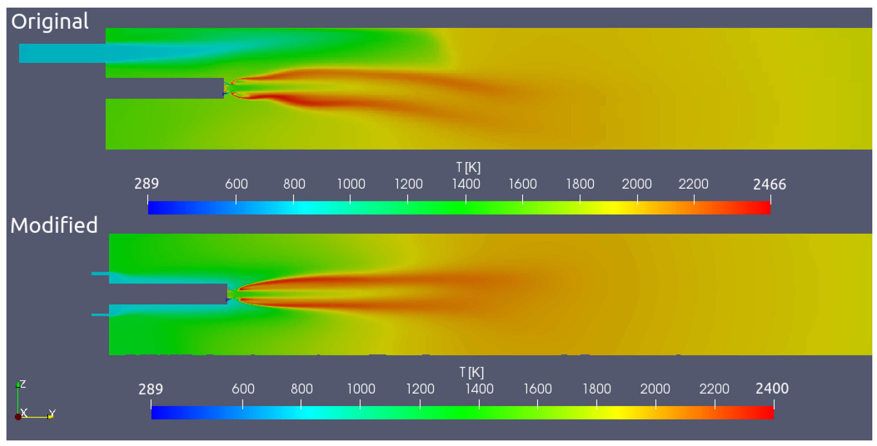
Figure 7 shows the vertical axial cross-section of the computed temperature near the flame region for the rectangular (top) and annular (bottom) secondary air inlet. A zone of high temperature is shown which approximates the location and shape of the flame. This zone corresponds to a thin reaction zone where the fuel and oxidizer meet. In the case of the rectangular inlet, the reaction zone can be seen to bend downwards due to the one-sided inflow on secondary from the top of the flame. In the case of the annular inlet, the reaction zone remains in the center of the enclosing walls.
Figure 8 shows the temperature on the interface between the freeboard gasses and the refractory lining. The solid and dashed dark lines correspond to the bottom and top wall in the rectangular configuration, respectively. The grey lines correspond to the annular inlet. All four graphs show a peak near the end of the flame and a linear decrease beyond the peak value. In the case of the rectangular inlet, the peak values of the bottom and top wall differ more than in case of the annular inlet. The peak values in the case of the annular inlet are lower than in the case of the rectangular inlet. At the top, the annular inlet yields the same peak temperature as the rectangular air inlet. Further downstream, the temperature of the annular inlet is slightly lower. These results can be explained by the fact that in the case of the annular inlet, the flame temperature is lower and the heat is mainly transported via radiation. The results for the rectangular air inlet are in good agreement with Figure 7 in [
10].


