1. Introduction
The heat transfer method and technology of fluids have been developed a long time ago. It has been further advanced in the last couple years due to the technological demand for more efficient ways to cool or heat materials in different industrial sectors. There are a great number of studies focused on nanofluid technology as a way to improve cooling and heating efficiency in different industries, such as processor and electronic chip cooling, nuclear reactor cooling, food processing facilities and for use as a replacement of existing cooling fluids in commercial buildings [
1,
2,
3,
4,
5,
6]. The objective of this paper was to investigate heat enhancement in a circular pipe in the presence of metal foam, twisted tapes, helical coils and a heat exchanger. The novelty is to create mixing without having to embark into a turbulent flow modelling study. The findings will be useful toward a design of new heat exchangers.
1.1. Nanofluid in Circular Pipe
Ho et al. [
7], conducted an experiment in a circular pipe using water-based suspensions of Al
2O
3 nanoparticles and microencapsulated nanoparticles. The nanofluid is known to enhance heat removal and the MicroEncapsulated Phase Change Material (MEPCM) nanoparticles were used for heat storage. This mixture of both particles in the fluid made the system very attractive for further investigation. The uniqueness of this study is that the authors were able to accurately measure the physical properties of the fluid for different concentrations of each particle type. It was found that the effectiveness of thermal diffusivity of nanofluids appears significantly increased, while the opposite effect is observed if MEPCM in water is used. Additional findings indicated that the forced convective cooling efficiency of incorporating the nanofluid, or the Phase Change Material( PCM) suspension as the heat transfer fluid in the tube heated with a certain heat flux strongly depends on the flow rate and particle fraction. In their investigation,
n-eicosane was the phase change material used. Saghir et al. [
8], further investigated numerically different types of fluid mixtures—binary and ternary—to study heat enhancement and heat storage in a circular pipe. The fluid mixture consisted of Al
2O
3 nanoparticles and MEPCM nanoparticles mixed in water. This new type of fluid shows a good heat enhancement and heat storage capability. It was found that microencapsulated phase change material nanoparticles in water is found to have an excellent heat storage capability when MEPCM is in molten condition. The higher the MEPCM concentration the better the heat storage achieved. A ternary mixture of Al
2O
3 and MEPCM nanoparticles in water is the best fluid for heat storage under any flow rate conditions. It is found that a 3%vol Al
2O
3 nanoparticles mixed with 20% vol MEPCM nanoparticles in water is the recommended fluid mixture. In addition, Sekrani et al. [
9], investigated the usefulness of nanofluids in heat enhancement. Their results predicted an enhancement not exceeding 6% assuming that no segregation or sedimentation of nanoparticles take place.
Bianco et al. [
10], investigated experimentally the heat transfer behavior on the water and ethylene glycol-Al
2O
3 nanofluids flowing in circular cross-section tubes. The results of the analysis presented that the heat transfer conductivity of the fluid increases with increasing the particle volume concentration, although that was increasing the shear stress value on the wall. They found that the temperature-dependent model increases in the heat transfer coefficient and Nusselt number and decreases the shear stress on the wall.
1.2. Twisted Tape in Circular Pipe
Later researchers investigated the insert of twisted tape in the pipe with the aim of creating a strong mixing even in the laminar regime to enhance heat extraction. Eiamsa-Ard et al. [
11], obtained results of heat transfer, friction factor and the thermal performance of a uniformly heated microtube which is equipped with a single and double twisted tape. Analysis was performed twice on the double twisted taps; when the blades were rotating in the same direction, and when they were rotating in an opposite direction. The study used two different values for the Reynolds number (5650 and 1700). It was reported that the double tapes models were higher for Nusselt number and thermal performance than the single tape model and the oppositely rotating taps had a higher Nusselt number than the same direction rotated model. The overall thermal performance factor of the micro-fin tube was increased by a factor of 2.03 by using the oppositely rotating taps. Kumar et al. [
12], conducted a study for a swirling air jet, running under different conditions, and then compared each one of them to get the best heat transfer characteristics. In the experiments, a bronze twisted tape was added into the jet nozzle in order to create a swirling effect. Four different twist ratios were used, and the distance between the jet and the surface plate varied from 1 to 4. The Reynolds number was maintained in the range of 500 to 3000. In addition, the researchers introduced another dimensionless parameter called swirl number, which is the ratio between the axial flux angular momentum to the axial flux axial momentum. They obtained an equivalent swirl number for each twist ratio used. The temperature distribution on the flat plate is an IR camera used to capture the temperature distribution when the airflow hits the plate. The results of the experiments showed that the best heat transfer characteristic was increasing when the twist ratio is between 1 to 4.5 and it decreased when the twist ratio was between 4 to 7.5. They also found that the heat transfer rate increases with Reynolds number and decreases with increasing distance of the jet to plate spacing.
Maddah et al. [
13], compared different heat transfer characteristics, using a shad, tube type heat exchanger with both water and nanofluid flowing in a plain tube, and nanofluid flowing in a twisted insert tube. The nanofluid used had a 0.01% vol concentration of titanium dioxide (TiO
2) nanoparticles with a water base fluid. The particle size was 30 nm, and the study was performed using various Reynolds numbers greater than 2300 and a counter-current flow. The results showed that by increasing the Reynolds number, the heat transfer coefficient increased for all three models. On the other hand, the nanofluid model in twisted tapes had a heat transfer coefficient which was approximately 20% higher than the base pure water model. The efficiency of the heat exchanger was 30% higher for the nanofluid twisted tape model than for water. The experiment also showed that using a nanofluid in twisted tapes increases the friction factor of the system by 2.5, suggesting that the size of the nanoparticles and the additional surface area for the twist tape has a significant effect.
1.3. Metal Foam in Circular Pipe
Huang et al. [
14], performed both experimental and numerical studies. The main objective of both studies was to determine how adding a porous medium to a tube influences the core flow. To do this, porous media with a diameter (marginally smaller than the tube’s diameter) were created and placed in the tube’s core. The type of porous media was altered, meaning porosities of 0.951, 0.966 and 0.975 were used, respectively, for different tests. Uniform heat flux was also applied to the walls of the tube, as a boundary condition. The type of flow experienced in the tube was also altered, meaning both laminar and fully developed turbulent was used. This was done to see the impact of each and how they relate to the performance of the porous media. In terms of the numerical study, it also analyzed how the pore radius ratio could be used to influence the heat transfer performance of the tube. The results showed that adding porous media influences the heat transfer rate by a factor between 1.6–5.5 (depending on the type of flow). The flow resistance also increased because the area of contact between the porous media and the fluid flow increased. For example, the heat transfer enhancement was overshadowed greatly by the flow resistance, deeming the addition of porous media in that particular case to be poor. Ghosh et al. [
15], conducted a study using an insert of metal foam in a circular pipe They did the analysis using a cubic shape structure from the metal foam, attached to an isothermal surface once and placed in between isothermal plates for another attempt. The analysis was done in order to gain a better understanding on the effect of the porosity and the density in the heat transfer characteristic of the metal foam. The analysis results concluded that the metal foam sink solution is more suitable for high Nusselt number and high flow applications.
Additional studies were done in a helical pipe [
16,
17,
18,
19]. The investigations focused toward the development of correlation to calculate the friction factor of laminar and turbulent flow. Nanofluids has been used in the analysis and it was found that the heat transfer decreases as the twist ratio increases.
According to our literature investigation, it was found that there are not many studies comparing the performance of nanofluids flowing in a twisted tube with metal foam and plain pipes. This provides an opportunity for more studies to highlight nanofluid technology with the arrangement of twist tape and metal foam in order to improve the performance of the nanofluid heat transfer characteristics and the cooling capability. In this current paper, an attempt is made to investigate the effect of the presence of inserts in a circular pipe. One may mention that the findings should be beneficial for the design of new heat exchangers for engineering applications.
Section 2 will present the problem description. In
Section 3, we present the finite element formulation.
Section 4 presents the analysis results such as the temperature changes, Nusselt number, friction factor and the thermal efficacy for different conditions. Finally,
Section 5 presents the conclusions.
2. Problem Description
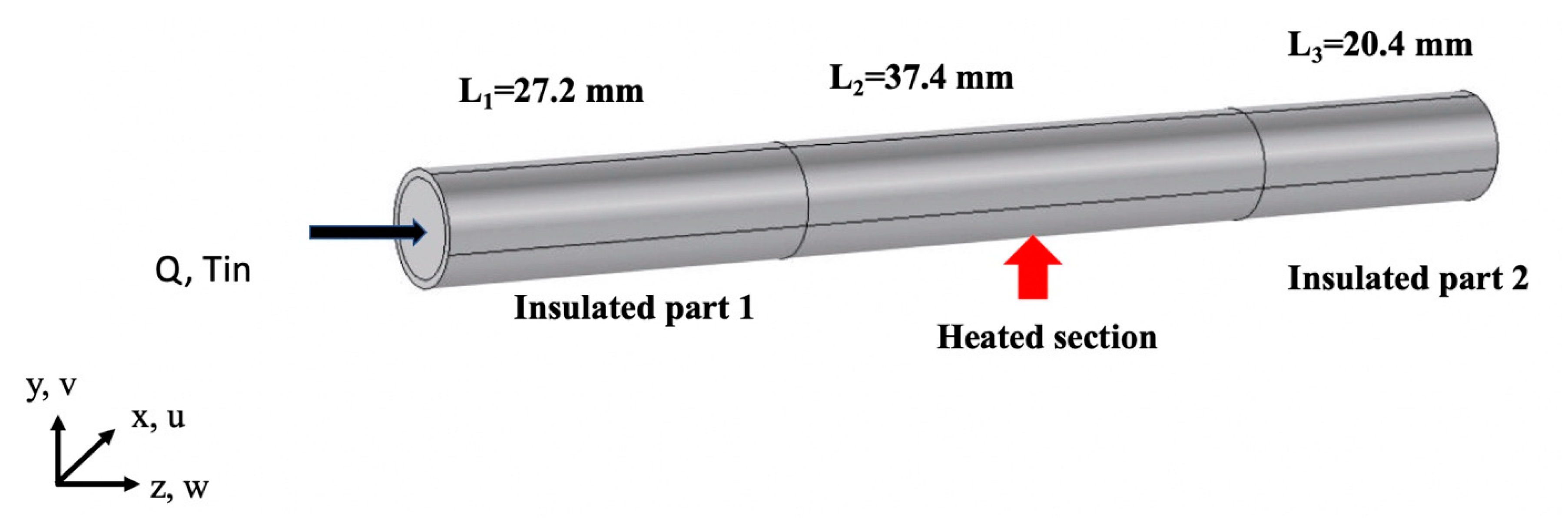
In this study, we present a detailed analysis of a circular cross-section pipe with different metal inserts. The aim is to determine which one is the most efficient to be used in the heat exchanger as the heat observer component, that will result in an increase in the heat exchanger’s overall efficiency. The problem consists of a circular pipe having a length L equal to 85 mm and an inner diameter equal to 6.8 mm and an outer diameter equal to 8 mm. The pipe is composed of three parts where the first part known as L
1, has a length 27.2 mm, followed by the heated section having a length L
2 equal to 37.4 mm and finally the third part insulated section L
3 equal to 20.4 mm. Part 1 and part 3 external surface is insulated and part 2 is heated externally with a heat flux q″ having an independent value of 50,000 W/m
2 and 75,000 W/m
2.
Figure 1 presents the model in question. Flow enters the pipe at a constant flow rate Q and an inlet temperature T
in equal to 18 °C. Three different cases were investigated. The aim is to select the best scenario leading to heat enhancement and the best thermal efficiency. In the first case, the inside the pipe is free allowing the flow to circulate along the length of the pipe. In the second case an insert made of aluminum oxide metallic foam having a porosity of 0.91 and a permeability equivalent to 10 PPI (i.e., 9.5478 × 10
−7 m
2) is investigated. In the third case, a metallic a single twist insert made of copper is studied in details. Calculated temperatures were investigated on the surface of the internal pipe in the heated part only. The pipe is made of copper with a thickness of 0.006 mm.
Figure 1 displays in details all components of the numerical setup.
3. Finite Element Formulation
The copper pipe’s heat transfer rate and thermal efficiency problem presented in this paper required solving the full Navier-Stokes equation, continuity equation and the energy equation. These equations were solved using COMSOL software (version 4.3a, COMSOL, Stockholm, Sweden) [
20], which utilizes a finite element method. A three-dimensional model has been created and three velocity vectors u, v, w, were added in the x, y, z directions, respectively. Two consistent stabilization methods were used which are the streamline diffusion and the crosswind diffusion. The pressure was the 4th parameter used in solving the problem. For the free flow in the model, the formulation adopted are as follows:
X-direction momentum equation:
Y-direction momentum equation:
Z-direction momentum equation:
Energy conservation equation:
The density of the fluid is , the dynamic viscosity is , the pressure is p, and g is the gravity vector. The three-dimensional velocities are u, v and w in the x, y and z direction, respectively. The specific heat of the fluid is Cpf and the conductivity is kf. Heat conduction formulation is used to study the heat in the copper pipe.
When an insert of porous medium is used, one needs to solve in conjunction with the Navier stokes equation, the Darcy-Brinkman formulation. The formulation in this case becomes:
X-direction Darcy-Brinkman:
Y-direction Darcy-Brinkman:
Z-direction Darcy-Brinkman:
and the energy equation used was the following:
The effective heat capacity takes into consideration the heat capacity in the liquid and in the solid matrix. Similarly, the effective conductivity combines the conductivity of the fluid and the conductivity of the metallic foam. Readers are invited to consult [
21], for more details.
3.1. Boundary Conditions
Two different heat fluxes were applied at the external wall of the middle section of the pipe as shown in
Figure 1. The first applied heat flux is 50,000 W/m
2, another equal to 75,000 W/m
2 was applied uniformly around the external wall. In order to remain in the laminar regime two Reynolds number were selected (1000 and 2000) leading to water flow rate of Q = 5.361 cm
3/s and Q = 10.722 cm
3/s respectively. If nanofluid is used, the flow rate is identical to the water flow rate because the kinematic viscosity of water and TiO
2 nanofluid is the same. The differences in physical properties between the two fluids are the thermal conductivity and the specific heat. The inlet fluid’s temperature is set equal to T
in = 18 °C, and the study runs in a steady state condition. At the outlet, open boundary is applied which means that normal stresses are set equal to zero. Because the inlet Reynolds number is set constant for different fluids, the mass rate will change from one case to another with changing fluid.
Table 1 presents the physical properties used in our calculation. The twisted tape used is a 1 mm thick full 360° rotated tape with the same length as the pipe itself.
3.2. Mesh Sensitivity
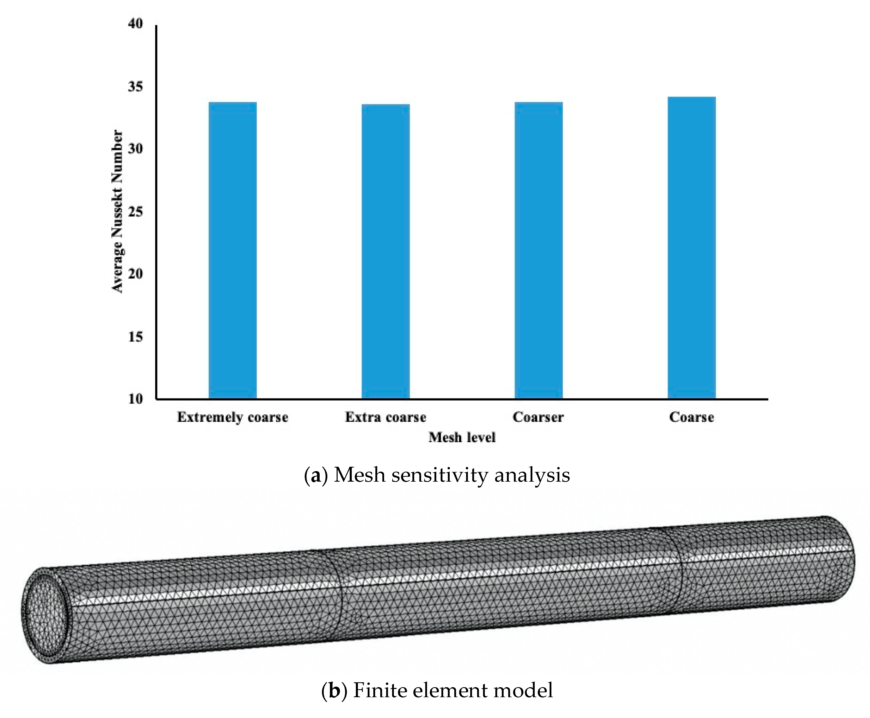
Before running different study cases on COMSOL, the mesh sensitivity was examined whether it was accurate enough to record the numerical results from the model. In the
Table 2, we demonstrated different mesh sensitivity that we can select using COMSOL software. The mesh levels that COMSOL supports and the elements numbers for each mesh level are shown above. The average Nusselt number was evaluated at the inner wall of the pipe for each mesh level, and the results are represented in the
Figure 2a. It is evident that a coarse level will be suitable to be used in the COMSOL model.
Figure 2b, presents the finite element mesh used in our simulation. In addition, the model has been tested by comparing the numerical data with some experimental results [
8]. The model consisted of the same boundary condition to the current one.
3.3. Pipe Inserts
In order to investigate the importance of flow behavior inside the pipe, two different types of insert have been included in the modelling. The first one consists of a metal foam porous medium. The porous insert is made of copper and its physical properties are presented in
Table 1.
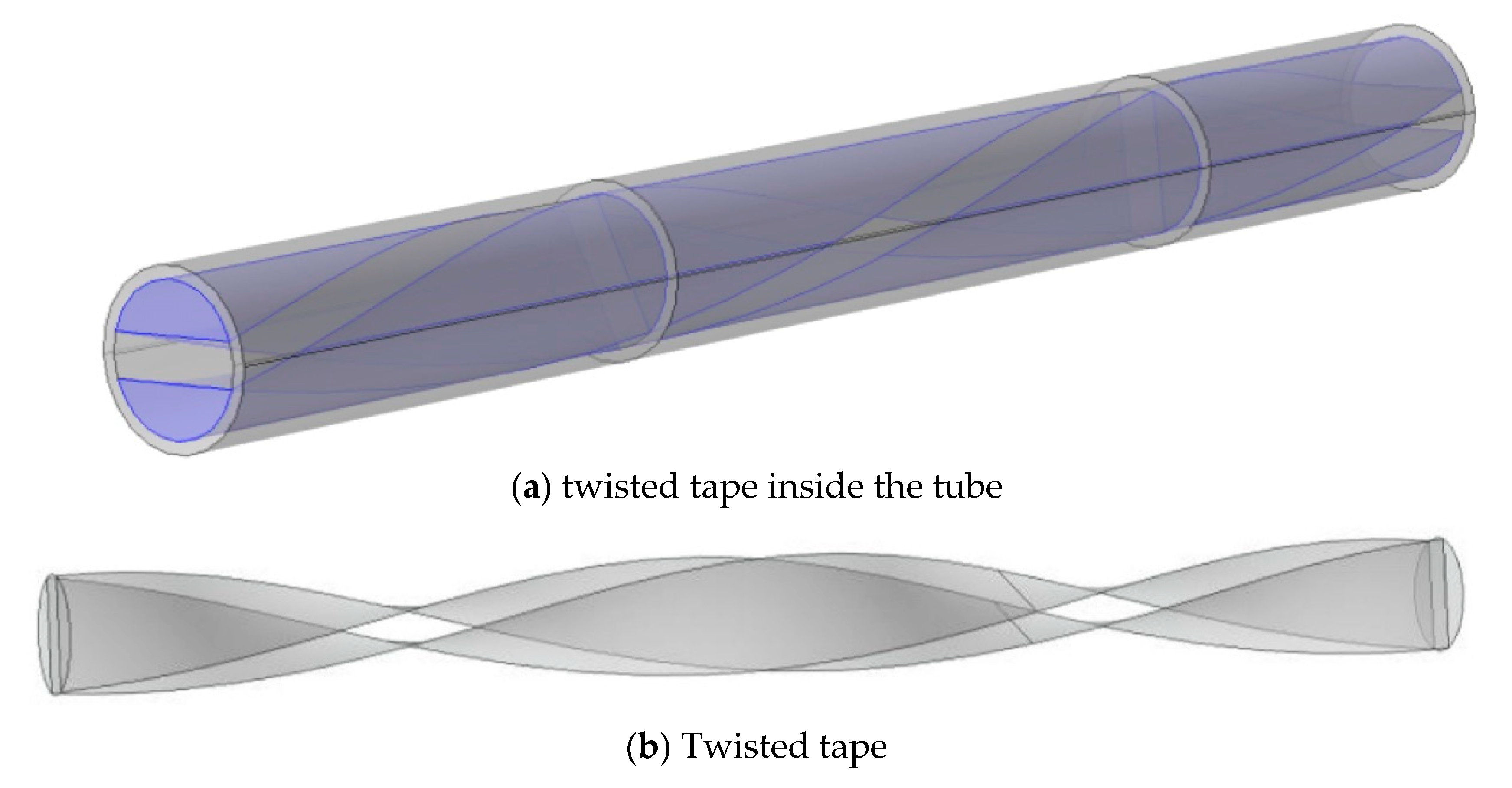
Figure 3a presents the twisted insert in the pipe and
Figure 3b presents the 360° single twist tape having a 2 mm thickness. The length (between two twists) is 40.8 mm and the diameter of the insert is identical to the internal pipe diameter of 6.8 mm. Thus, in this particular case the ratio of the twisted length to the diameter is equal to 6.
4. Results and Discussion
This paper focuses on examining the best pipe model to be used for heat enhancement and heat extraction. As indicated previously, three different types of pipe model were investigated. The first pipe is a hollow cylinder heated in one external surface and insulated at the remaining surface using internal fluid circulation to extract heat. The second configuration is identical to the previous configuration with a porous insert. The third configuration is identical to the first configuration but with a 360° single twist tape insert. In order to keep the investigation under the laminar regime valid in all the scenarios two different Reynolds numbers of 1000 and 2000 were adopted. This translates into flow rates of 5.361 cm3/s and 10.722 cm3/s for both water and TiO2 nanofluid. The inlet temperature is always maintained constant at 18 °C.
4.1. Temperature and Nusselt Number Variation
The temperature has been measured at the wall of the internal pipe along the heated section only.
Figure 4,
Figure 5 and
Figure 6 highlight the temperature variation for the three configurations.
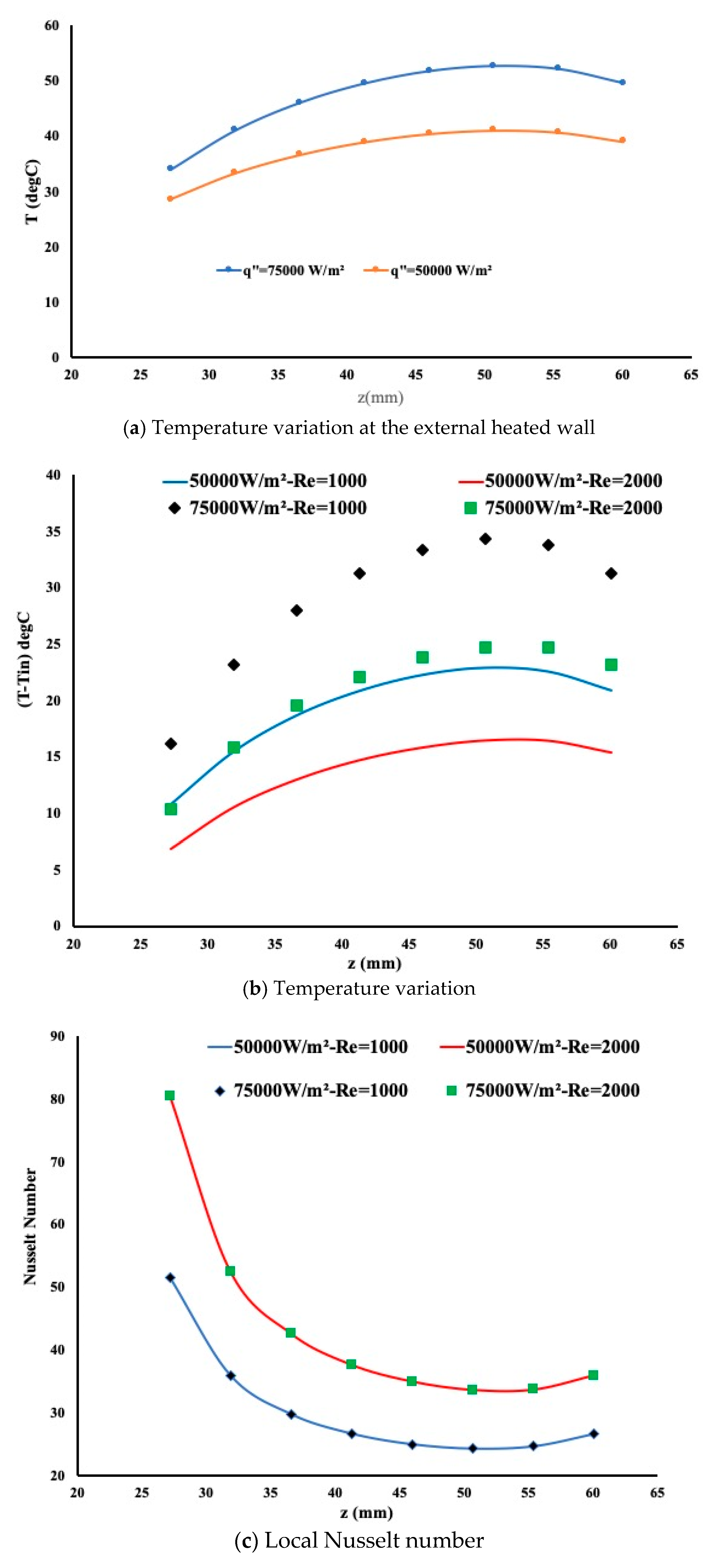
Figure 4a presents the temperature variation at the external heated wall. A high temperature is observed and the temperature profile is expected. In
Figure 4b the temperature variation is non-linear mainly near the end of the heated section. As the Reynolds number increases, the flow rate leads to more cooling of the internal wall. The temperature profile is identical for the cases, however, the Nusselt number is evaluated as well to examine the heat enhancement. By definition, the local Nusselt number is calculated as follows:
where h is the heat convection coefficient, D is the pipe diameter and k
w is the water thermal conductivity. The heat convection coefficient h is calculated as follows:
Figure 4c presents the Nusselt number variation for the two conditions. Due to the laminar regime, the Nusselt number is independent of the heating intensity and provide a limited heat enhancement for a constant Reynolds number. However, as the Reynolds number increases the heat enhancement is more pronounced.
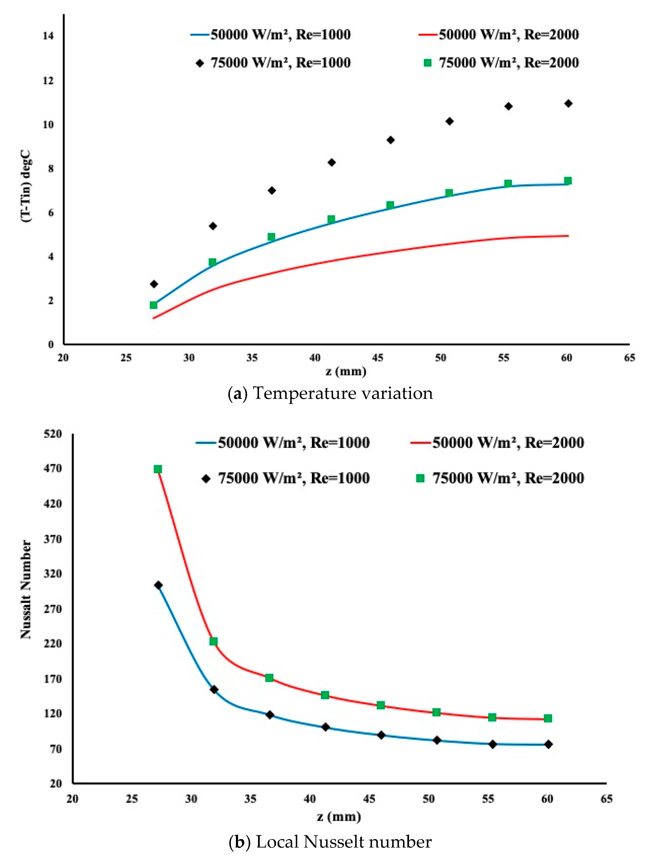
Similarly, the heating and the flow rate are applied when a porous insert is implemented in the model. By examining
Figure 5a, a slower flow rate leads to more heat extraction as observed in the previous case. In addition, the presence of a porous medium forces the flow to exert more contact with the pore and thus more heat is extracted. The temperature variation is almost linear contrary to the previous case where the linearity is removed towards the end of the heated section.
Figure 5b presents the local Nusselt number variation. It is evident from this graph that heat extraction is more pronounced in the presence of a porous insert as the local Nusselt number is larger in magnitude.
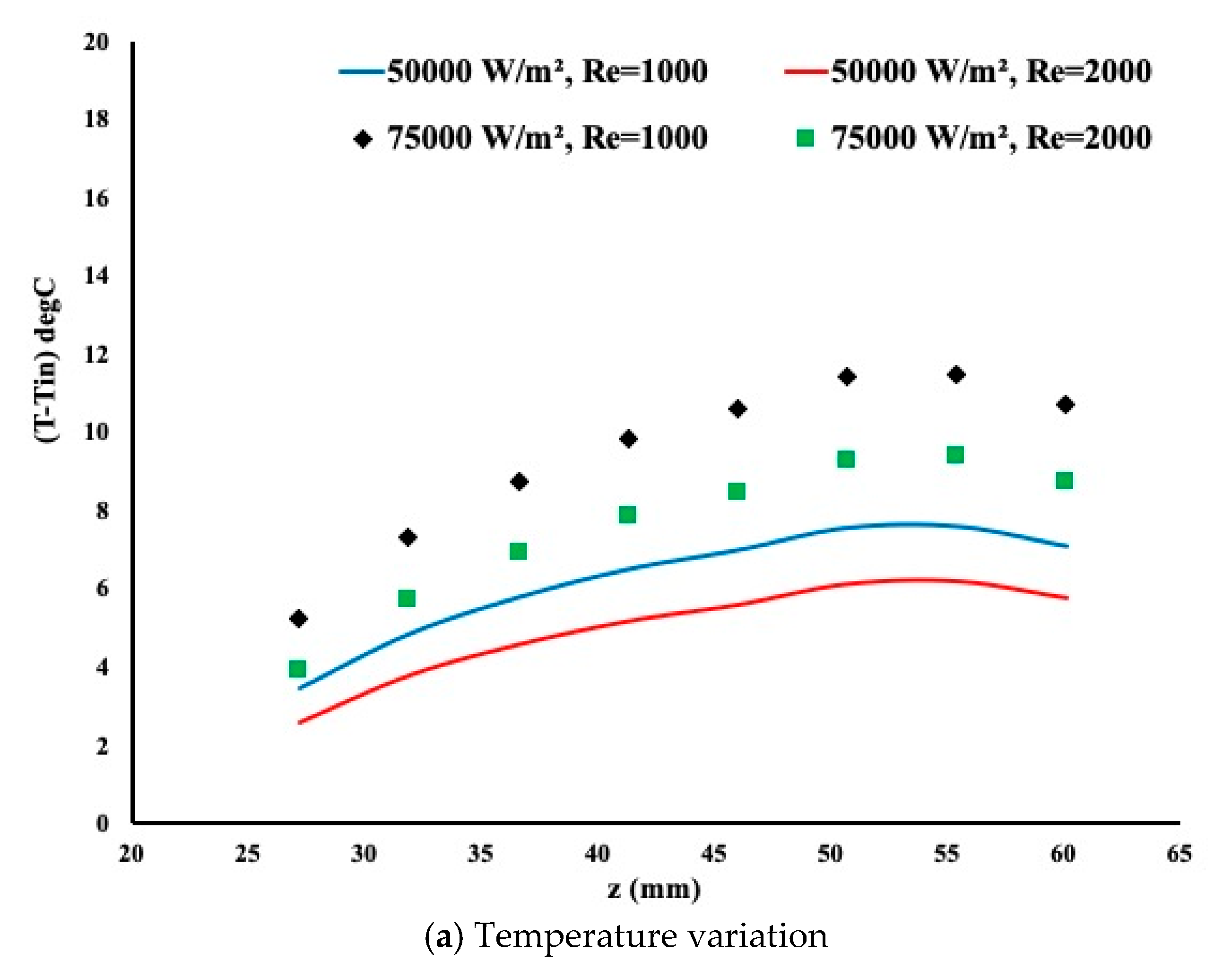
Figure 6 showed the temperature variation and the local Nusselt number when a twisted tape insert is implemented. Interestingly enough one may judge the shape of the temperature as between that of a hollow pipe displayed in
Figure 4 and a porous configuration as shown in
Figure 5.
The waviness of the temperature is due to the measurement of temperature. In some locations, the insert touches the internal pipe wall creating a drop of the temperature due to metal contact. However, this waviness is very small and unnoticeable.
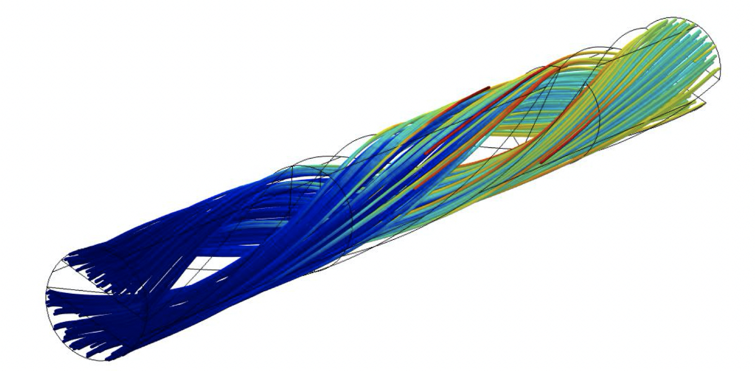
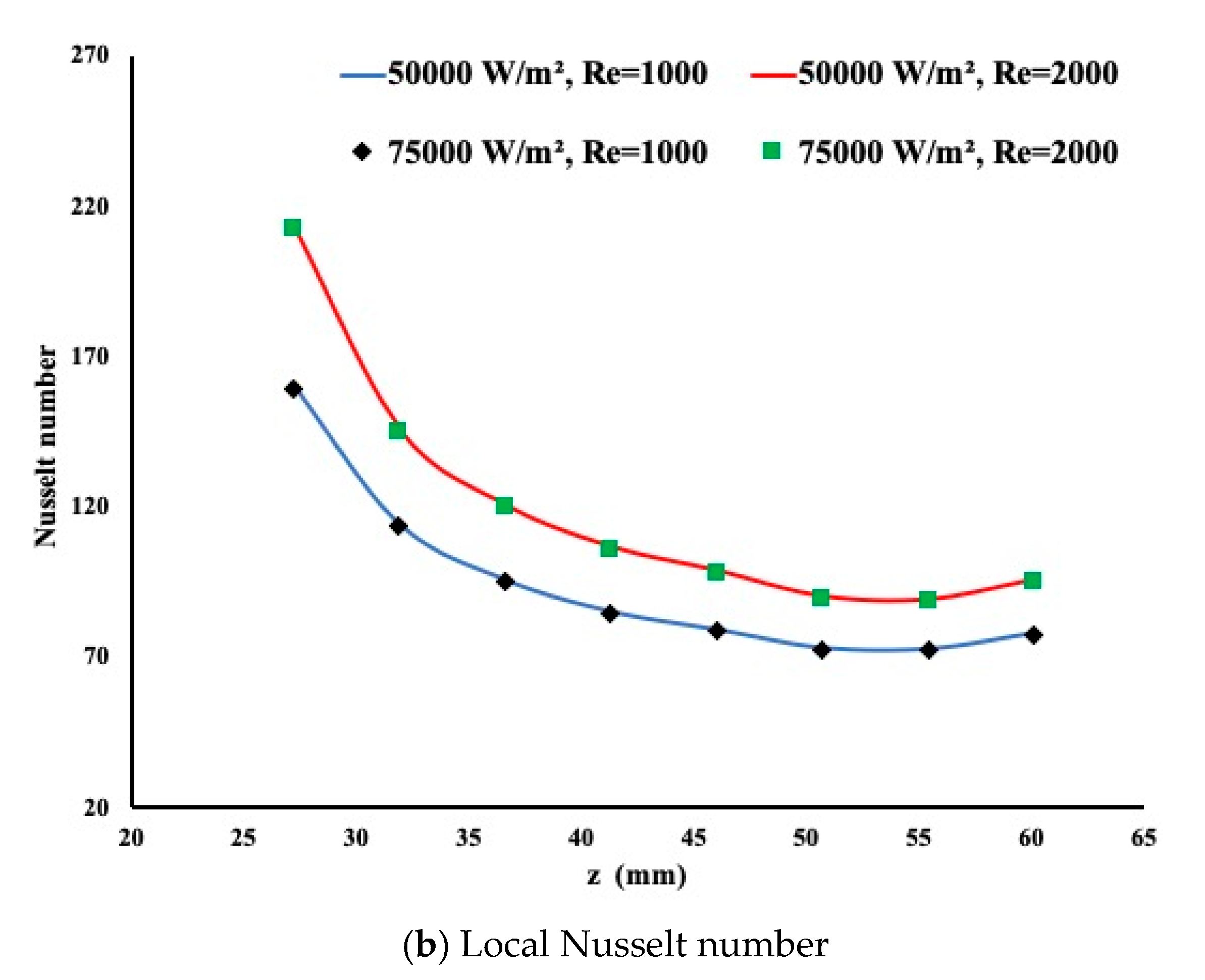
Figure 6b displays the local Nusselt number. It is obvious that the heat extraction is more pronounced compared to a regular pipe but the porous insert provides a better heating enhancement. Although for a hollow pipe the flow is fully developed in the case of twisted insert (
Figure 7) the flow structure inside the pipe was observed, forcing the fluid to extract the best possible of heat from the pipe. The amount of heat extraction is constant regardless of the heating conditions due to the laminar regime.
4.2. Friction Factor Variation
Friction factor is an important parameter to be investigated. Although water is the working fluid but in the presence of the insert it may affect the pumping power. By definition, the friction factor is defined as:
where
is the pressure change between the pipe inlet and outlet in kPa, D is the diameter of the pipe, L is the length of the pipe and
is the fluid density and w is the fluid velocity on the z direction.
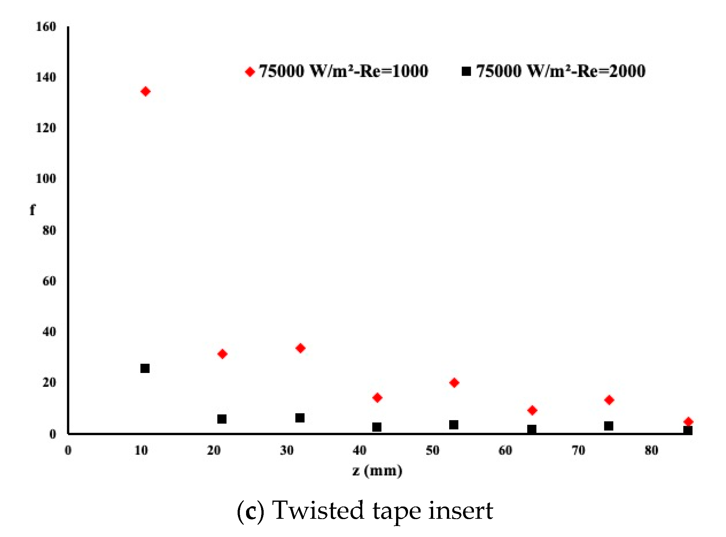
Figure 8 presents the friction coefficient along the entire length of the pipe for a heat flux of q″ = 75,000 W/m
2 and for two different Reynolds numbers. It is evident that the flow in the plain pipe exhibited the lowest friction coefficient when compared to the porous insert case or the twisted tape case. However, as observed earlier in the presence of a twisted tape case or porous case, the heat extraction showed better performance at the expense of a higher friction coefficient. As the Reynolds number increases, the friction coefficient increases correspondingly. The variation pattern along the flow direction is the same for the case of plain pipe and twisted insert. However, fluctuation in the pattern exists for the porous insert due to the non-uniform flow circulation between the pores.
4.3. Thermal Efficiency Ratio
Thermal efficiency is the most accurate parameter to identify the best configuration related to heat extraction. It has been demonstrated that some configurations may provide a good heat enhancement but at the expense of a high friction coefficient and therefore a pressure drop. Other configurations provide a low heat enhancement at the expense of low pressure drop. By definition, the thermal efficiency is defined as follows:
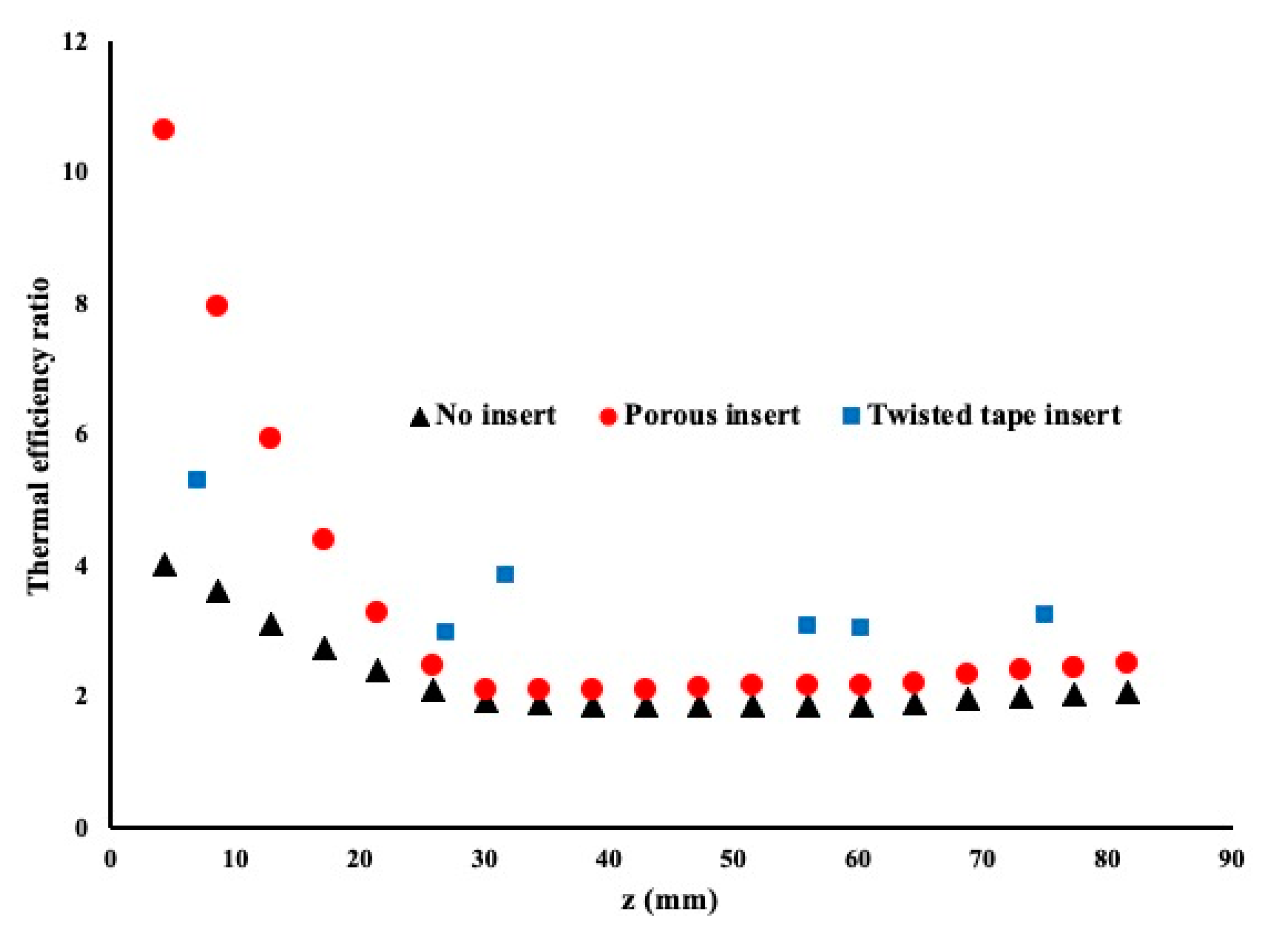
In the current comparison,
Figure 9 presents the thermal efficiency ratio of the case of Reynolds number equal to 2000 over the case where the Reynolds number is equal to 1000. This coefficient is calculated along the entire pipe. The heat flux is set equal to 75,000 W/m
2 and the inlet temperature is maintained at 18 °C.
As shown in
Figure 9, it is evident that a twisted insert provided the best thermal efficiency followed by the porous insert. The flow mixing as well as the flow through a porous structure is evident for the good performance of such pipe as a heat exchanger. Because the twisted tape touches the inside diameter of the pipe at different location, the point shown in
Figure 9 are at the wall of the internal pipe diameter where no contact exists between the twisted tape and the pipe.
4.4. Effectiveness in Using Nanofluid as Working Fluid
In the present work, the distilled water working fluid showed that the insert of a twist pipe provided the best thermal efficiency when compared to a porous insert or plain pipe. The reason is due to the mixing phenomenon happening in the entire pipe. Two factors may have influenced the performance of the heat enhancement, the low friction coefficient and the high heat extraction provided by high Nusselt number. In order the study the importance of working fluid in heat extraction, the model was repeated using a nanofluid. The nanofluid consist of 1% vol TiO2 nanoparticles in distilled water. The metallic nanoparticles have a diameter of 50 nm and are uniformly distributed in the solution.
Table 3 presents the physical properties of the nanofluid. The model was computed for the three configurations for two different Reynolds number of 1000 and 2000, respectively. The heat flux was maintained constant at 75,000 W/m
2 with a constant inlet temperature of 18 °C. In this section the ratio of the thermal efficiency of the nanofluid to distilled water is discussed with the aim to highlight the usefulness of using nanofluid.
Figure 10 presents the study case for no insert. As shown, the nanofluid provided a better performance when compared to distilled water regardless of the Reynolds number. A very large heat enhancement with an average of 22% is noticeable for a Reynolds number of 2000 and 15% enhancement for a Reynolds number of 1000. Both fluids had very small pressure drops but the high conductivity of the nanofluid and nearly similar viscosity led to a better performance of the nanofluid over water.
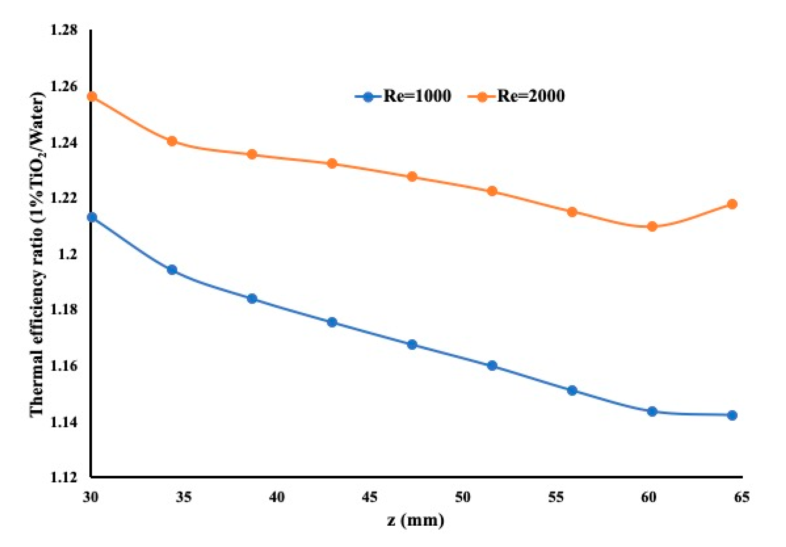
Figure 11 presents the same scenario but with a porous insert. The insert is identical to the previous model, having a porosity of 0.91. This copper metallic insert helps heat extraction regardless of whether the working fluid is a nanofluid or distilled water. In this figure, one may notice that the nanofluid outperforms distilled water but with a heat enhancement of an average 2% when the Reynolds number is equal to 2000 and 0.5% when the Reynolds number is equal to 1000. The difference in performance for the two different Reynolds numbers is due to higher flow rate when the Reynolds number is equal to 2000. Nerveless the nanofluid demonstrated here its capability to improve the heat enhancement when compared to water.
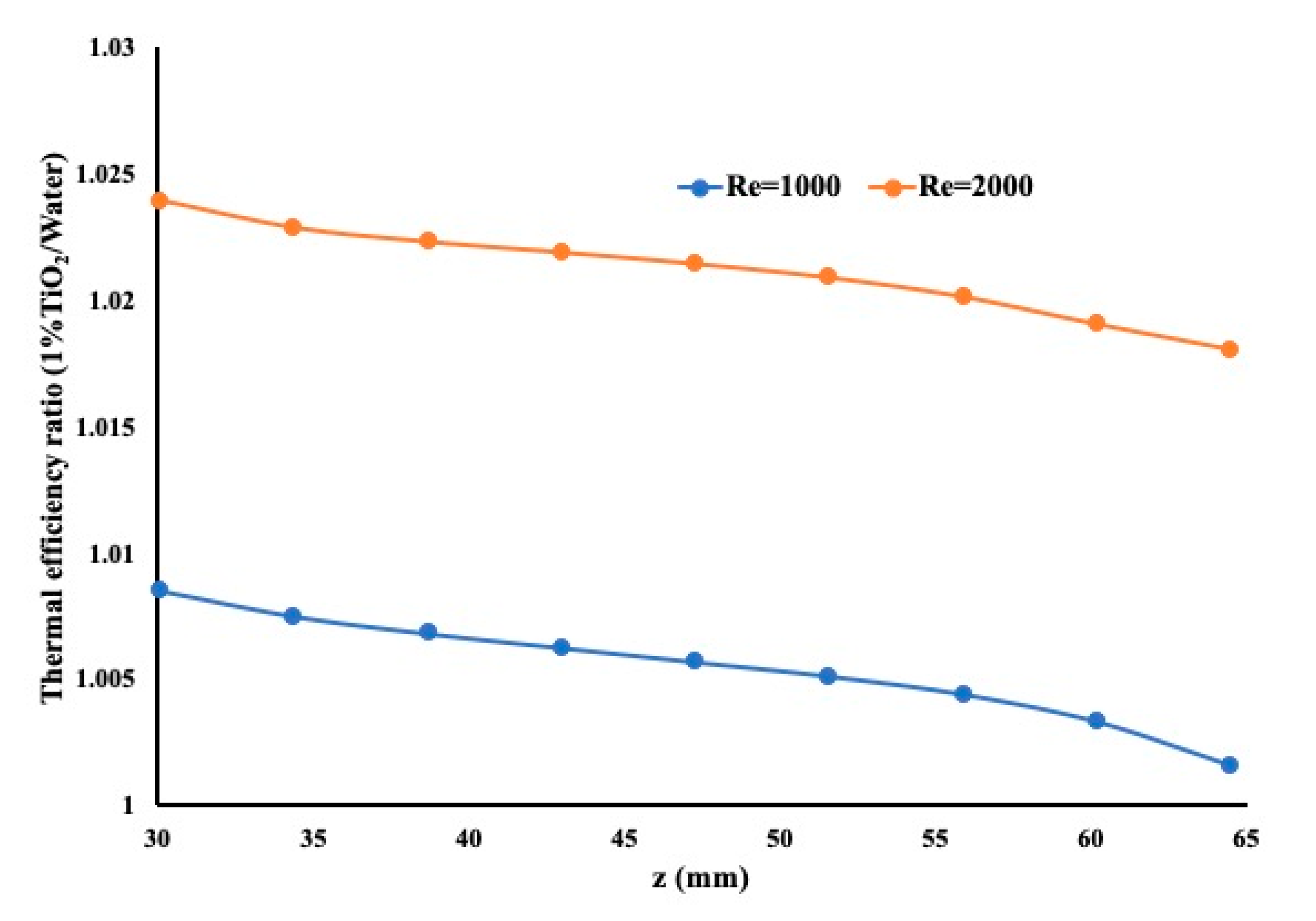
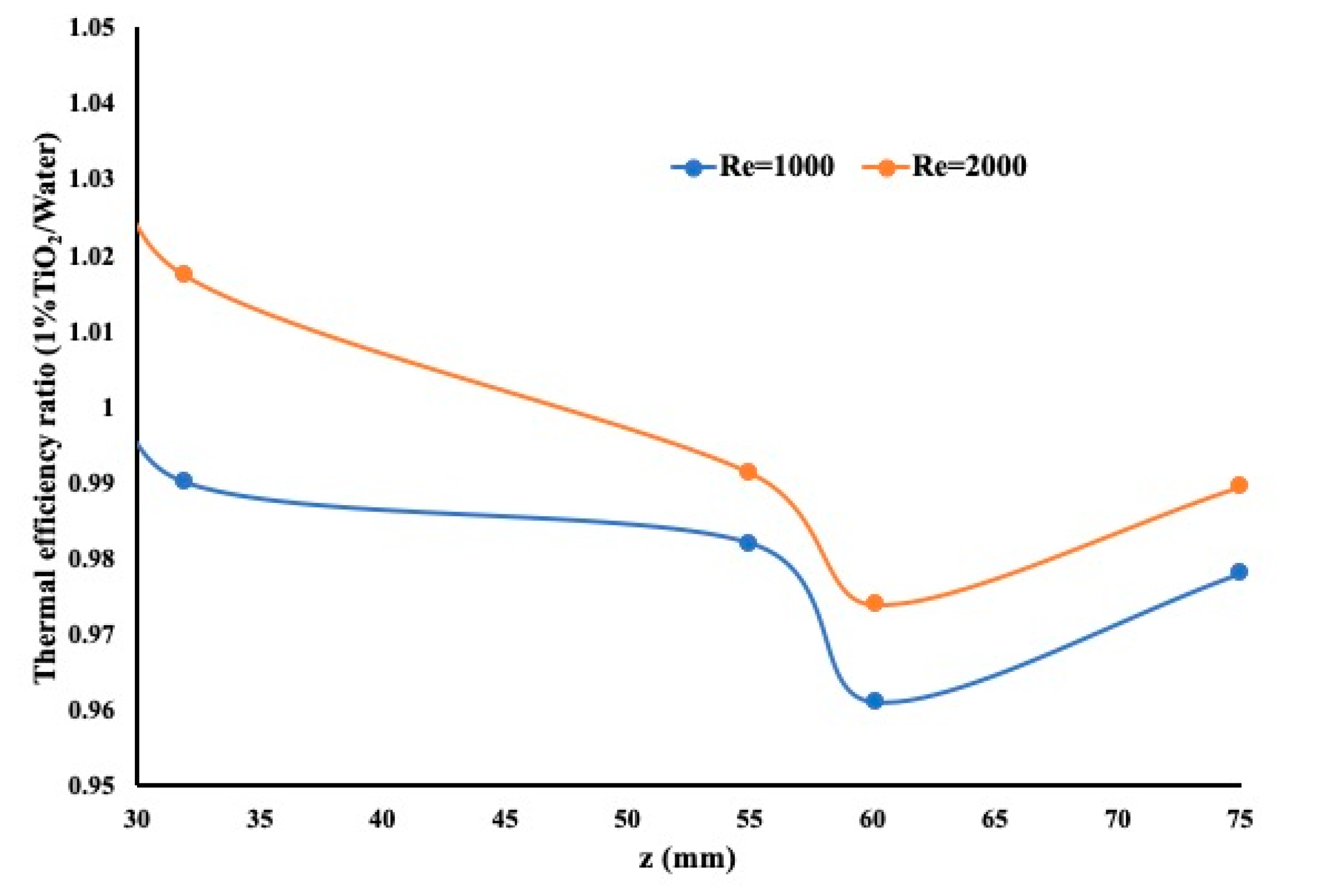
Finally, the study has been extended to a twisted tape insert as shown in
Figure 12. It is evident from the results presented in
Figure 12 that the nanofluid did not perform as expected. It is strongly believed that the mixing effect, while in laminar regime, provides the best heat extraction regardless of whether a nanofluid is used or not. It is also important to mention that the twisted tape is attached at some of its part to the internal wall of the pipe thus making it difficult to identify a location to measure the flow velocity.
5. Conclusions
The findings of the current study of the heat enhancement for three different pipe assemblies showed the following:
- (1)
The temperature increases by increasing the heat flux and decreases by increasing the Reynolds number. As the working fluid changes from water to a nanofluid, the heat extraction by the nanofluid is in general more pronounced due to its higher conductivity.
- (2)
The Nusselt number value is higher in the presence of a porous insert but at the expense of a higher friction coefficient.
- (3)
The thermal efficiency of the twisted tape insert pipe is higher than that of a porous medium insert pipe and a plain pipe. This is mainly due to the strong mixing effect.
- (4)
A nanofluid provided a better heat enhancement in a plain pipe and with a porous insert when compared to water via thermal efficiency. However, for the twisted pipe, the nanofluid performance was weak compared to water as working fluid. Thus, one can simply avoid using a nanofluid and simply use a twisted pipe insert.
Author Contributions
Conceptualization, M.Z.S.; methodology, K.P. and M.Z.S.; software, K.P. and Z.A.H. validation, K.P.; formal analysis, K.P., Z.A.H. and M.Z.S.; investigation, K.P., Z.A.H. and M.Z.S.; resources, M.Z.S.; data curation, M.Z.S.; writing—original draft preparation, K.P., M.Z.S. and Z.A.H.; writing—review and editing, K.P., M.Z.S. and Z.A.H.; funding acquisition, M.Z.S. All authors have read and agreed to the published version of the manuscript.
Funding
The authors acknowledge the full financial support of the National Science and Engineering Research Council Canada (NSERC), Ryerson University for the financial support and Qatar National Research Foundation (NPRP12S-0123-190011).
Conflicts of Interest
The authors declare no conflict of interest.
Nomenclature
| u, v, w | Velocity of the fluid in m/s |
| Tin | Inlet temperature (°C) |
| T | Measured temperature (°C) |
| x, y, z | Coordinates in mm |
| P | Pressure in Pa |
| q″ | Heat flux in W/m2 |
| L | Length of the pipe in mm |
| D | Pipe diameter in mm |
| Density in kg/m3 |
| Viscosity in kg/m s |
| Cpf | Specific heat in J/kg K |
| kf | Conductivity |
| kw | Conductivity of water |
References
- Wang, X.-Q.; Mujumdar, A.S. Heat transfer characteristics of nanofluids: A review. Int. J. Therm. Sci. 2007, 46, 1–19. [Google Scholar] [CrossRef]
- Wang, X.; Xu, X.; Choi, S.U.S. Thermal conductivity of nanoparticle-fluid mixture. J. Thermophys. Heat Transf. 1999, 13, 474–480. [Google Scholar] [CrossRef]
- Maıgga, S.E.B.; Nguyen, C.T.; Galanis, N.; Roy, G. Heat transfer behaviours of nanofluids in a uniformly heated tube. Superlattices Microstruct. 2004, 35, 543–557. [Google Scholar] [CrossRef]
- Halelfadl, S.; Estellé, P.; Aladag, B.; Doner, N.; Maré, T. Viscosity of carbon nanotubes water-based nanofluids: Influence of concentration and temperature. Int. J. Therm. Sci. 2013, 71, 111–117. [Google Scholar] [CrossRef]
- Halelfadl, S.; Maré, T.; Estellé, P. Efficiency of carbon nanotubes water based nanofluids as coolants. Exp. Therm. Fluid Sci. 2014, 53, 104–110. [Google Scholar] [CrossRef]
- Das, S.K.; Putra, N.; Thiesen, P.; Roetzel, W. Temperature dependence of thermal conductivity enhancement for nanofluids. J. Heat Transf. 2003, 125, 567–574. [Google Scholar] [CrossRef]
- Ho, C.J.; Chang, C.Y.; Cheng, C.Y.; Cheng, S.J.; Guo, Y.W.; Hsu, S.T.; Yan, W.-M. Laminar forced convection effectiveness of Al2O3-water nanofluid flow in a circular tube at various operation temperatures: Effects of temperature-dependent proper-ties. Int. J. Heat Mass Transf. 2016, 100, 464–481. [Google Scholar] [CrossRef]
- Saghir, M.Z.; Bayomy, A. Heat enhancement and heat storage for a ternary mixture in a circular pipe. Therm. Sci. Eng. Prog. 2018, 5, 32–43. [Google Scholar] [CrossRef]
- Sekrani, G.; Poncet, S.; Proulx, P. Modeling of convective turbulent heat transfer of water-based Al2O3 nanofluids in an uniformly heated pipe. Chem. Eng. Sci. 2018, 176, 205–219. [Google Scholar] [CrossRef]
- Bianco, V.; Manca, O.; Nardini, S. Numerical investigation of transient single phase forced convection of nanofluids in circular tubes. WIT Trans. Eng. Sci. 2008, 61, 3–12. [Google Scholar] [CrossRef]
- Eiamsa-Ard, S.; Wongcharee, K. Heat transfer characteristics in micro-fin tube equipped with double twisted tapes: Effect of twisted tape and micro-fin tube arrangements. J. Hydrodyn. 2013, 25, 205–214. [Google Scholar] [CrossRef]
- Kumar, S.; Hindasageri, V.; Prabhu, S. Local heat transfer distribution on a flat plate impinged by a swirling jet generated by a twisted tape. Int. J. Therm. Sci. 2017, 111, 351–368. [Google Scholar] [CrossRef]
- Maddah, H.; Aghayari, R.; Farokhi, M.; Jahanizadeh, S.; Ashtary, K. Effect of Twisted-Tape Turbulators and Nanofluid on Heat Transfer in a Double Pipe Heat Exchanger. J. Eng. 2014, 2014, 1–9. [Google Scholar] [CrossRef]
- Huang, Z.; Nakayama, A.; Yang, K.; Yang, C.; Liu, W. Enhancing heat transfer in the core flow by using porous medium insert in a tube. Int. J. Heat Mass Transf. 2010, 53, 1164–1174. [Google Scholar] [CrossRef]
- Ghosh, I. Heat-Transfer Analysis of High Porosity Open-Cell Metal Foam. J. Heat Transf. 2008, 130, 034501. [Google Scholar] [CrossRef]
- Zhao, H.; Li, X.; Wu, Y.; Wu, X. Friction factor and Nusselt number correlations for forced convection in helical tubes. Int. J. Heat Mass Transf. 2020, 155. [Google Scholar] [CrossRef]
- Pathipakka, G.; Sivashanmugam, P. Heat transfer behaviour of nanofluids in a uniformly heated circular tube fitted with helical inserts in laminar flow. Superlattices Microstruct. 2010, 47, 349–360. [Google Scholar] [CrossRef]
- Prabhanjan, D.; Raghavan, G.; Rennie, T. Comparison of heat transfer rates between a straight tube heat exchanger and a helically coiled heat exchanger. Int. Commun. Heat Mass Transf. 2002, 29, 185–191. [Google Scholar] [CrossRef]
- Xin, R.C.; Ebadian, M.A. The Effects of Prandtl Numbers on Local and Average Convective Heat Transfer Characteristics in Helical Pipes. J. Heat Transf. 1997, 119, 467–473. [Google Scholar] [CrossRef]
- COMSOL. Software User Manual; COMSOL: Newton, MA, USA, 2020. [Google Scholar]
- Alhajaj, Z.; Bayomy, A.; Saghir, M. A comparative study on best configuration for heat enhancement using nanofluid. Int. J. Thermofluids 2020, 8, 100041. [Google Scholar] [CrossRef]
| Publisher’s Note: MDPI stays neutral with regard to jurisdictional claims in published maps and institutional affiliations. |
© 2020 by the authors. Licensee MDPI, Basel, Switzerland. This article is an open access article distributed under the terms and conditions of the Creative Commons Attribution (CC BY) license (http://creativecommons.org/licenses/by/4.0/).


