1. Introduction
The outer shelf and shelf break constitute some of the most important and challenging regions of the world oceans. As discussed by Brink [
1], the importance arises from the fact that this is where significant amounts of nutrients, biological matter, pollutants, and other material are exchanged between coastal regions and the deep ocean. Concurrently, observing and predicting significant exchange events in this region is challenging. As documented in some detail 25 years ago by Huthnance [
2] and more recently by Brink [
1], the difficulties arise from the plethora of physical processes operating in this zone and their disparate time and space scales.
Generally, the flow along shelf breaks is composed of relatively energetic along-isobath currents with cross-shelf flows associated with tides and turbulent processes. Moreover, atmospheric processes and the interactions of this flow with deep-ocean eddies may produce intense, yet brief cross-shelf exchange and significant upwelling and vertical transport [
3]. These mechanisms combine to produce significant inhomogeneity in the spatial structure of fields, such as temperature, salinity, and other tracers, and of the currents themselves. The consequent range of time and space scales involved is sufficiently large to pose challenges for all but the most comprehensive field programs, as well as for basin-scale general circulation models to resolve.
Prior studies of the exchange across shelf regions, such as reported in [
4,
5], focused on property gradients and mixing coefficients based on climatological data, hydrographic cruises, and moorings. These studies were useful for establishing seasonal to climatological trends in specific geographic regions. However, as demonstrated by the application to transport of oil into near-shore waters during the Deepwater Horizon oil spill [
6], such data do not adequately account for the transport across the shelf even in relatively quiescent periods. This suggests that there may be important but heretofore overlooked background cross-shelf transport processes.
To fill this gap, we test the hypothesis that aperiodic cross-shelf transport can arise from a combination of simple periodic processes that frequently form the background shelf circulation. For present purposes, it is sufficient to use a model that considers just three processes, specifically the interaction of a coastal current modulated by a topographic wave disturbance and tides. Each process by itself can only lead to periodic fluid exchange. Even a combination of any two of these is insufficient; but as we shall demonstrate, together, these three processes have the potential to lead to significant aperiodic cross-shelf water exchange.
As transport is essentially a Lagrangian process, we employ appropriate Lagrangian methods to elucidate particle behavior in such a flow. Since the early work of Bower [
7], Samelson [
8], and Rogerson et al. [
9] on fluid exchange across meandering jets, the application of these methods has produced significant progress in understanding transport in geophysical flows. See also Wiggins [
10], Haller [
11], Samelson and Wiggins [
12], Budyansky et al. [
13], and Pratt et al. [
14] for more recent results and references. Here, we extend this approach to jet flow over a sloping bottom. However, we choose to present the results relative to a Eulerian reference to make our results more amenable to oceanographic observations.
The balance of this report is organized as follows. The next section reviews the model and analysis methods. A base case with typical parameter values is analyzed in detail and basic transport properties described in
Section 3. This is followed by an extensive exploration of the model parameter space in
Section 4. In
Section 5, we apply the model to recent data from the Texas-Louisiana Shelf. This region is chosen because it is generally typical of shelf and upper slope regions in the world and because of the availability of recent hydrographic data. Our report concludes in
Section 6 with a summary and discussion of some broader implications for cross-shelf transport.
2. Model and Methods
In order to analyze the transport associated with tidal oscillations in the presence of a classic coastal jet with a topographic Rossby wave disturbance, we turn to the theoretical framework developed by Kuehl [
15]. This setup leads to an analytic solution for the transport function and hence the velocity field. Trajectories are computed numerically, using a standard explicit fourth order Runge-Kutta scheme. Details of the model are provided in
Section 2.1, followed by the methodology to identify Lagrangian structures in
Section 2.2 and for transport quantification in
Section 2.3.
2.1. The Model
The flow of interest consists of the following components: (1) a coastal jet in the form of an along-slope mean flow with peak velocity located offshore; (2) a traveling wave, such as a topographic Rossy wave, with a multi-day period; and (3) a higher frequency tidal oscillation. Here, we will consider the simplest case of a barotropic flow along slope topography with Ekman dissipation [
15]. Note that extensions to the non-linear case [
16] and to stratified flow [
17] are relatively straightforward, but beyond the scope of the present study.
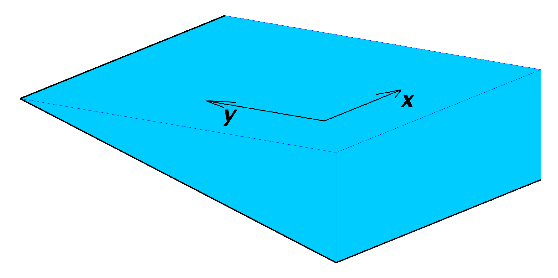
We adopt a right-handed coordinate system with
x in the along-shore direction and
y in the cross-shore direction, where
at the center of the coastal jet. The coastal jet is typically directed in the negative
x-direction, with shallower waters for higher values of
y. See
Figure 1. In the region of interest, the bathymetry is taken to be a simple constant slope of the form:
for constants
and
S. The three flow components are assumed to be linearly additive and are modeled individually. The linear superposition assumption is justified when the background flow is small. Within the jet core, the relative vorticity gradients may modify the topographic wave structure, but on the scale of the shelf, topographic effects dominate.
The mean flow is assumed to be steady and linear, with Ekman dissipation in a bottom boundary layer as the dominant viscous term and the cross-stream shear dominating the relative vorticity. Under these conditions, the vorticity-streamfunction formulation of the shallow water equations [
18,
19] can be solved for the volume-transport streamfunction. The solution takes on the form of an error function:
A determines the strength of the coastal jet, while parameterizes its width. In general, varies with x, so that the jet widens downstream. In an effort to isolate the lowest order dynamics, we approximate as a constant, which corresponds to the limit of vanishing dissipation.
The traveling wave can generically be modeled by
. For typical topographic waves, which follow isobaths,
. To fix the analysis window, a frame of reference is chosen that moves with the wave at phase speed
. With both of these modifications, the associated volume-transport streamfunction simplifies to:
B sets the amplitude of the wave disturbance, and
k is the wavenumber. For a topographic Rossby wave, the phase speed
and wavenumber
k do not vary independently, because of the dispersion relation (e.g., [
20]):
Here,
is the topographic beta parameter, and
is the Rossby number, where
g is the gravitational constant and
f is the Coriolis parameter. For typical values explored here,
R and
k are sufficiently large that this dispersion relation can be well approximated by:
Substituting this expression and the definition for
into the equation for
leads to the relationship:
Other dispersion relations can be implemented to model different topographically controlled waves, such as continental shelf waves.
Finally, the high-frequency tidal oscillations are represented as a generic periodic time dependence in the cross-shelf direction only:
C and indicate the tidal amplitude and frequency, respectively.
Putting the pieces together yields the following volume-transport streamfunction:
The corresponding velocity field takes the form:
Thus, the along-shore flow, u, consists of the background jet component, plus the effect of the moving frame of reference. The cross-shore flow, v, reflects the spatial oscillations of the topographic wave and the temporal oscillations of the tide. It is assumed that the model domain is sufficiently far from the coastal boundary, so that boundary effects do not impact the analysis.
The model is controlled by a total of ten parameters,
A,
,
B,
k,
C,
,
,
S,
f, and the time interval
over which the volume transport is computed. Not all of these parameters have direct physical interpretations. Therefore, we replace them with ones that do. These are summarized, with their definitions in terms of the basic ten parameters, their physical meaning, units, and base case values, in
Table 1. With these derived parameters, the fundamental model equations become:
where
and
2.2. Lagrangian Structures: Finite-Time Lyapunov Exponents
One tool to map out the transport properties of a complex flow is the field of finite-time Lyapunov exponents (FTLEs) [
21]. FTLEs are a common method for approximating Lagrangian coherent structures (LCS), i.e., manifolds that organize the domain into regions of different flow properties. For detailed discussions of LCS, the reader is referred to the comprehensive synopses by Wiggins [
10] and Haller [
11] and the references cited therein.
The FTLE is defined as follows: Consider the flow map
, mapping initial position
to a final position
at time
T. The Cauchy–Green deformation tensor is defined as
, where
denotes the matrix transpose. If the largest eigenvalue of
G is
, then the FTLE is defined as
. FTLE can be computed in forward and backward time. Ridges in the forward FTLE field (shown in red here) are frequently associated with stable manifolds, while those in the backward FTLE field (shown in blue) generally mimic unstable manifolds (this is not always true: flows undergoing rapid transition can experience transport across FTLE ridges [
22]). Intersections of stable and unstable manifolds demarcate hyperbolic regions in the flow. Material approaches such an intersection along the stable manifold and leaves along the unstable manifold.
While the velocity field for the model is analytic, the trajectories underlying our analysis are computed numerically, using a fourth order Runge–Kutta scheme. Similarly, the elements of the strain tensor
are computed by integrating along trajectories:
following Huntley et al. [
23].
2.3. Transport Quantification
For quantifying transport, we compute the area in the horizontal plane of the water masses in question and multiply by the depth. For this purpose, the depth is approximated as stepwise constant over segments m.
A quantitative theoretical tool for Lagrangian transport analyses is lobe dynamics [
12]. The basic idea is that a lobe, defined by two consecutive intersection points of the same two manifolds and the manifold segments in between, moves from outside to inside the area of interest. This kind of calculation works best in idealized, e.g., [
9,
24], or slowly evolving flows, e.g., [
25,
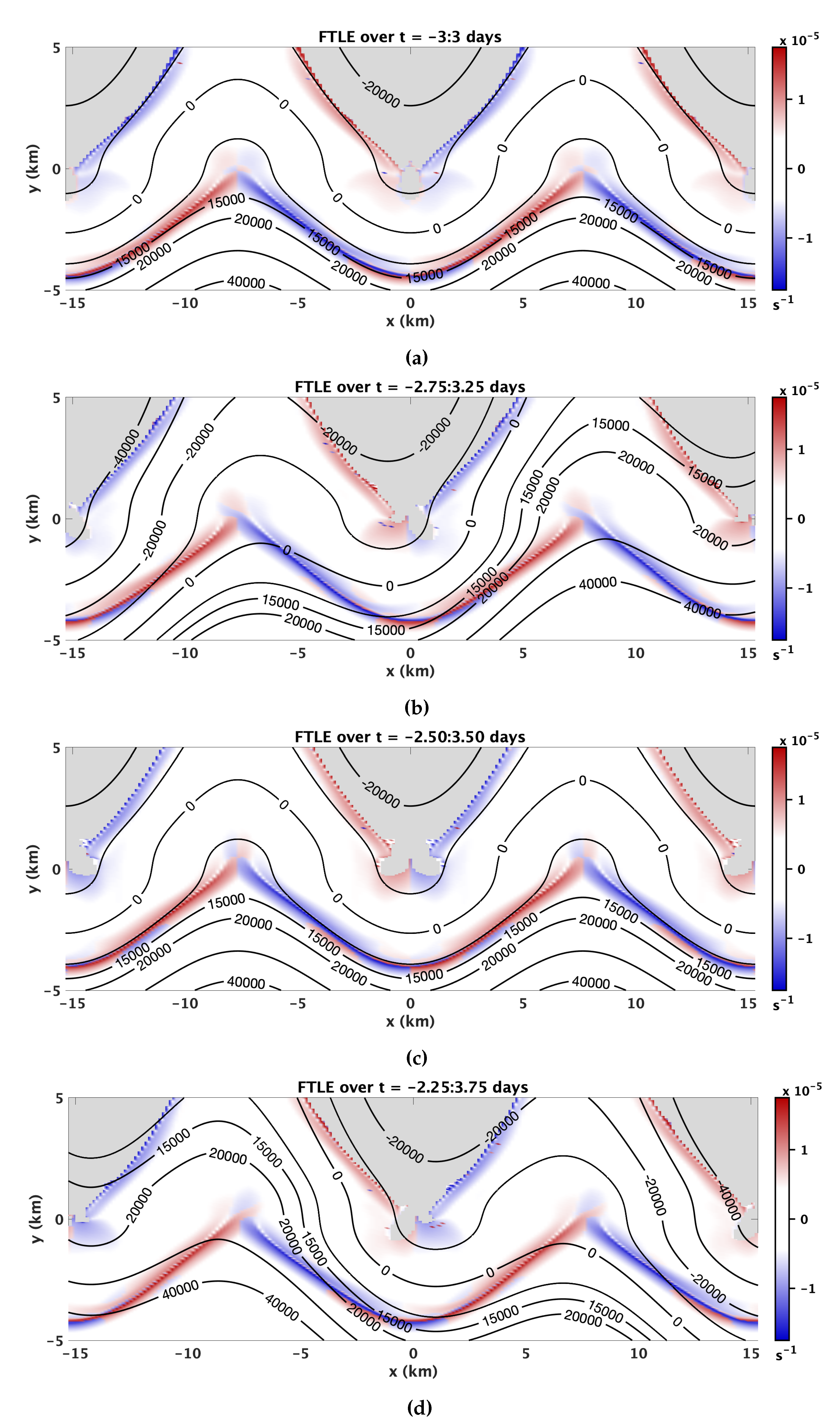
26], where the manifolds are sharply defined. However, in the present case, this methodology is complicated in part of the parameter space by the hyperbolic regions in the FTLE field being relatively weak and not stationary (see
Section 3 and Figure 3), while for different parameter choices, multiple ridges appear in close proximity (not shown), making the problem prone to numerical errors. Significant variations in the Lagrangian structures across the parameter space add further challenges. The best choice for how to define the boundary segments from a Lagrangian analysis for the areas of interest is therefore not clear. Moreover, the primary question we seek to address is the shoreward transport across the jet. Therefore, we chose not to pursue lobe dynamics.
There are two natural options for defining the boundary for the cross-shelf transport. One is the plane, where the center of the unperturbed coastal jet is situated. This is equivalent to transport across the line of constant depth m. Due to its connection to a topographic line, this definition of “cross-shelf” transport is easy to apply to observations. The other option is the plane defined by that crosses at . This plane moves with the flow, but returns with the tidal period to its initial position. Its main advantage is that it is more directly related to the flow structures. That is, in the case, there is no transport across , while there is transient transport across . Thus, in this manuscript, we chose to quantify cross-topographic transport relative to .
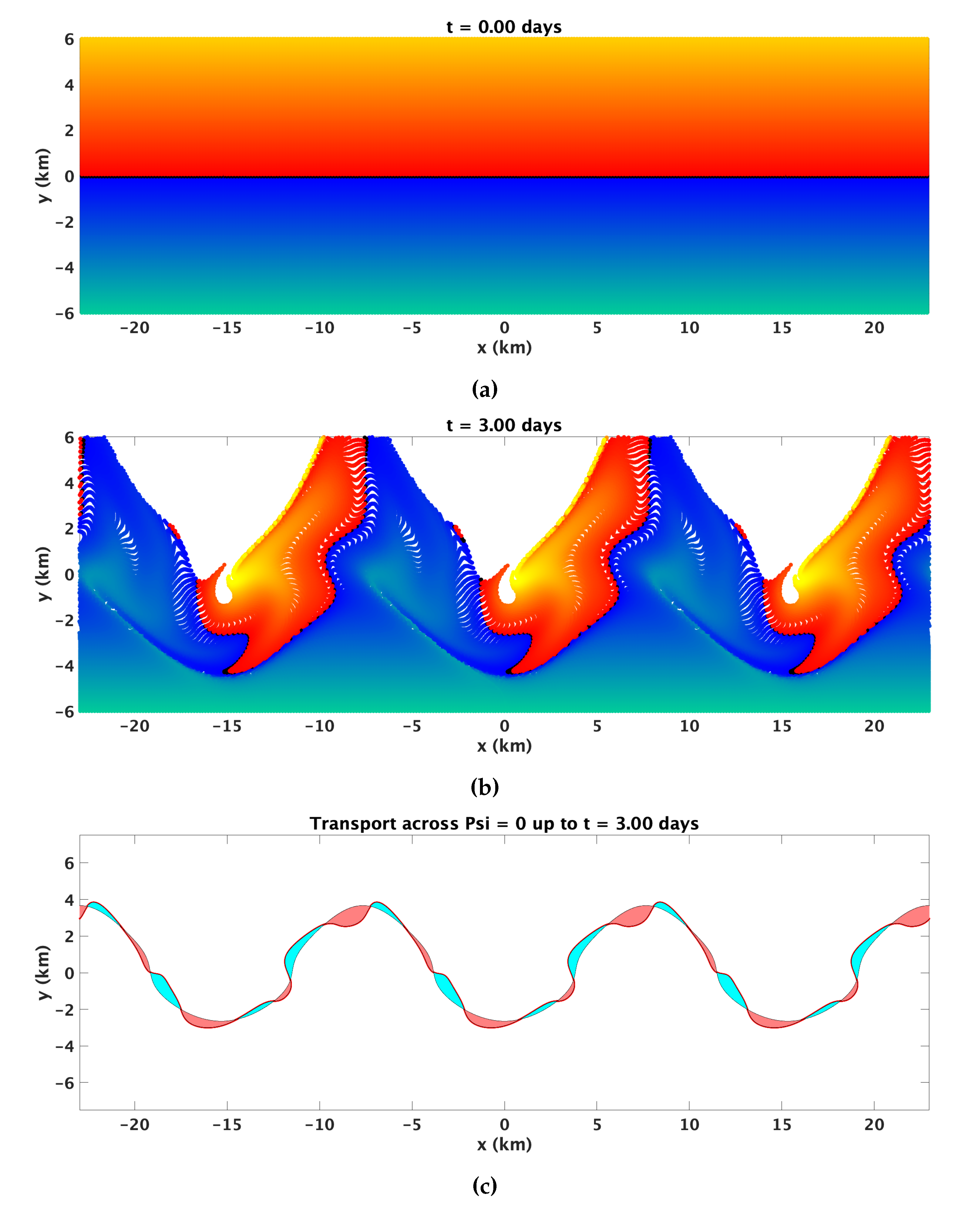
Concretely, the transport calculation is performed by parameterizing the curve with 1001 evenly spaced particles over two wave periods that are advected using the analytic velocity field and a fourth order fixed-step Runge–Kutta scheme. As distances between adjacent particles exceed 100 m, new particles are added along a linear interpolation between these particles. The area is then computed between the initial and final realizations of the curve. The transport magnitude is reported as the volume exchanged from onshore to offshore, which is equivalent to the volume exchanged in the other direction.
4. Parameter Space Exploration
The transport volume cited in
Section 3.2 is specific to the model configuration for the base case defined by the parameters in
Table 1. This raises the question of how the transport varies with the parameters. The ten-dimensional parameter space is too vast for exhaustive exploration. Therefore, we will instead focus on three secondary non-dimensional parameters that capture the relative importance of the different flow components. These are summarized in
Table 2. Elements that are kept constant are the latitude
, the water depth at the peak of the coastal jet
, the tidal parameters
and
, and the analysis time interval
.
The non-dimensional parameters consider the topographic wave speed relative to the strength of the coastal jet (
), a cross-shelf velocity advective length scale (the integral of Equation (
12) at
and
over half a tidal wave period) relative to the tidal amplitude (
), and the shelf width relative to the coastal jet width (
). We chose these particular combinations of model parameters because they are based on easily measured quantities and because they reflect the competition of the relevant physical processes. In particular,
accounts for the relative strength of the two components of along-shore flow (see Equation (
11)). The second non-dimensional parameter,
, considers the length scale the material has to move beyond the jet to be effectively mixed with coastal waters. Lastly,
accounts for the effectiveness of the shelf width to the jet width in cross-shelf transport.
Each of the non-dimensional parameters is varied over a range centered on the base case, capturing realistic values for the underlying physical variables. Transport volumes are computed for each case over three tidal periods and one wavelength interval by varying the numerator or denominator of each ratio. We have chosen to fix
, rather than varying it with
T, for better comparability. Note that the wavelength
is a function of
k, which in turn varies with
S and
T (Equation (
13)):
Thus, the wavelength changes with and if T and S are varied, respectively.
Of course, not all ten physical parameters are captured by the three non-dimensional ones investigated, and so, the general parameter space is not completely explored here. Indeed, for each series, we chose to change the smallest number of physical parameters. One consequence of this is that , , and are not varied completely independently. In particular, is linked to both of the other parameters: when is varied by adjusting the numerator (S) while keeping the denominator (L) constant, it impacts , because k and hence are a function of S. On the other hand, when is varied by adjusting the denominator (L), this changes , which is directly a function of L. Varying by adjusting L, of course, has a similar effect on . However, can be varied without impacting by varying T when adjusting the numerator.
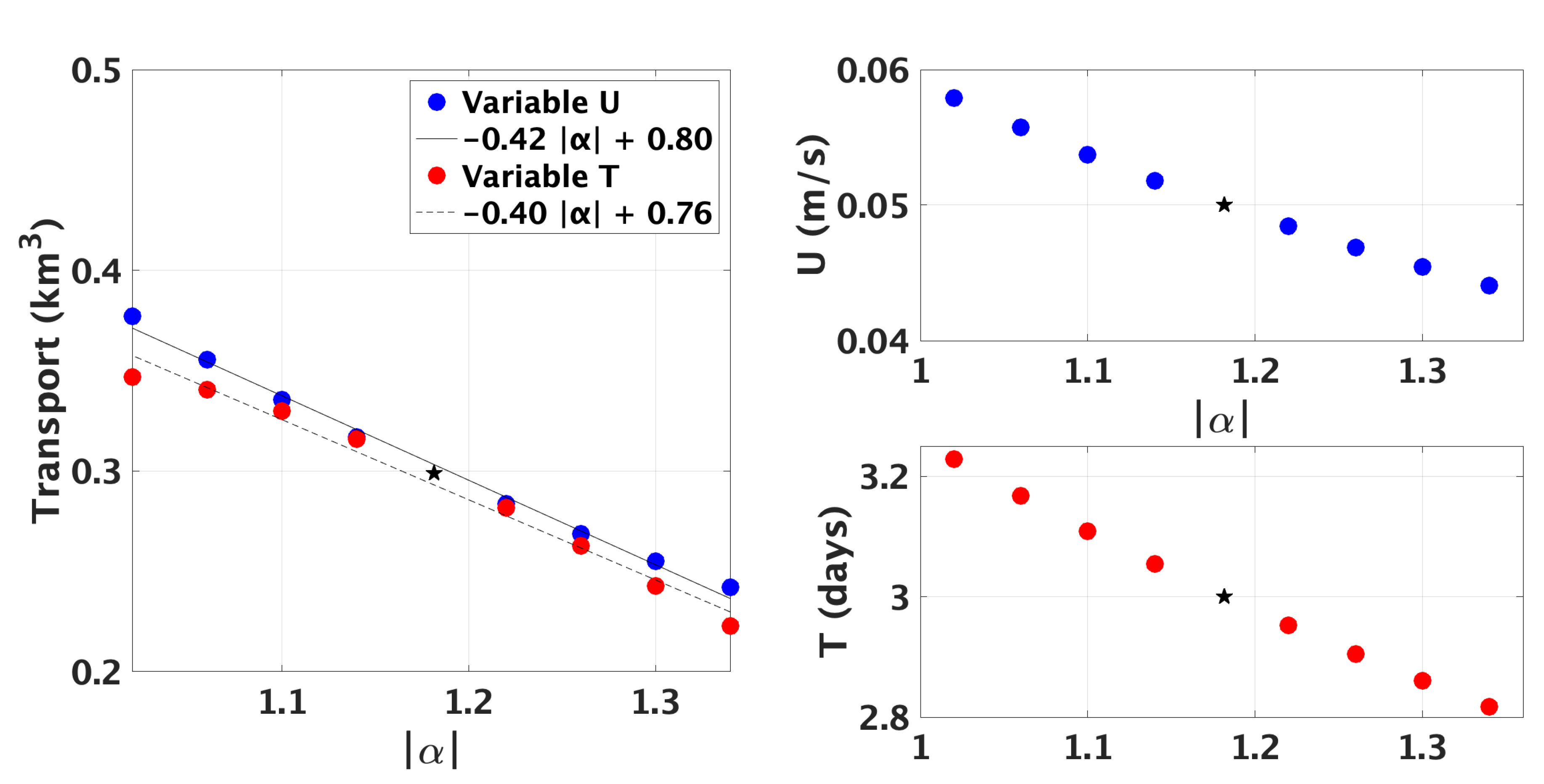
The results of the parameter space exploration are summarized in
Figure 5,
Figure 6 and
Figure 7, which also show how the corresponding physical parameters are varied for each experiment series. For those cases with near-linear dependence over the parameter space considered, linear fits are provided to quantify the strength of the parameter dependence.
Figure 5 shows the two experiment series for
, which measures the wave speed relative to the jet strength, varying the numerator and denominator separately. They nearly coincide, with a stronger correspondence than for the other two parameters. Apparently, this is due to the co-dependency on the other non-dimensional parameters mentioned above. This confirms that the ratio of the wave speed to jet strength is indeed a controlling parameter for the cross-shelf transport. In the parameter range explored here, the wave and jet act in opposite directions, and hence,
. As their respective magnitudes approach each other (
), the strength of the combined along-shore flow acting as a barrier to cross-shelf transport weakens, allowing increased transport.
The dependency of the transport on
is more subtle (
Figure 6).
measures the strength of the cross-shelf advection versus the width of the jet. It is observed that there is a sweet spot maximizing transport near
. The transport results from particles crossing the velocity gradients at the jet edge. Generally, for small
, as the jet is very wide or the cross-shelf advection weak, this process is inhibited. On the other hand, for very large
as the jet becomes very narrow relative to the cross-shelf advection, much of the cross-shelf advection occurs outside the influence of the jet, leading to only periodic transport. It takes both along- and cross-shelf advective components to generate advective mixing, both along and across topography in this case. For
at either extreme, only one component dominates.
The trends of transport with
are considered in
Figure 7.
measures the influence of the shelf width relative to the influence of the jet width. To make sense of these results, recall that an increasing
is accompanied by an increasing
if
L is varied and by an increasing
if
S is varied (via changes in
; Equation (
6)). It appears that for this part of the parameter space, these secondary effects dominate. For the case of constant
S and varying
L, transport is fairly insensitive to
, but a slight peak occurs around
, where
. In contrast, for constant
L and varying
S, transport decreases with increasing
and correspondingly increasing
, which leads to a strengthened barrier in the form of along-shore currents. Note that all the trends considered here are consistent with the fundamental idea that advective transport relies on a balance between cross-topography and along-topography advection.
Lastly, throughout this section, has been kept constant. However, tidal currents can vary greatly between geographic locations. Thus, we independently explored the impact of varying on the total transport. Predictably, stronger tidal currents were found to result in larger transport. In the range m/s, transport increased from 0.22 to 0.46 km, almost linearly with slope 12.7 km/(m/s) (not shown).
5. Application to the Texas Shelf
To test the conclusion of significant cross-shelf transport due to the three processes captured in this transport model for a specific case with corresponding observed parameter values, we consider an example of flow along the Texas Shelf. In general, circulation on the Texas Shelf exhibits a strong wind-driven seasonal pattern [
27,
28,
29]. During the winter months (October–March), a high pressure system typically sets up over Texas, inducing a down-coast wind field (blowing to the southwest, from Houston to Port Aransas). This wind field generates a down-coast oceanic circulation pattern, in which advection of buoyant river discharge and Ekman dynamics combine to create a strong (0.5–0.75 cm/s) down-coast Texas Coastal Current. The downwelling signature of this circulation pattern is often masked by the homogenization of the water column due to strong wind induced mixing. Winter months are also characterized by the passage of strong fronts, which enhance such mixing and cause short-lived coastal current reversals (1–2 days) with higher variability closer to the Texas-Mexico border (
N). In contrast, the summer months (June–August) are characterized by up-coast wind patterns (wind blowing to the northeast, from Port Aransas to Houston). This up-coast wind pattern drives a “reversal” of the Texas Coastal Current, causing up-coast flow near the Texas coast. Due to the reduced strength of summer winds and the passage of fewer fronts, an upwelling circulation pattern can be observed. The transitional months September–October (up-coast to down-coast) and April–May (down-coast to up-coast) are characterized by high variability due to instabilities associated with flow transitions.
In addition to wind-induced circulation, the Texas coast is also influenced by river discharge [
30] and offshore eddies impinging on the coastal zone [
31,
32,
33]. Freshwater plumes can act as barriers to cross-shelf transport [
34]. High river output has also been linked to increased offshore transport [
30]. Offshore eddies in this area are typically between 100 and 300 km in diameter, extend up to 1000 m in depth, have circulation velocities of a few cm/s, and primarily influence the Texas coastal zone in two ways: direct impingement on the Texas Shelf or impingement on the Louisiana slope. If impinging directly on the Texas Shelf, the eddies are capable of overwhelming the ambient circulation pattern and creating significant cross-topography transport. If impinging on the Louisiana slope, they can generate topographically controlled slope currents and topographic waves, which travel along the slope towards Texas [
35,
36,
37,
38,
39,
40,
41].
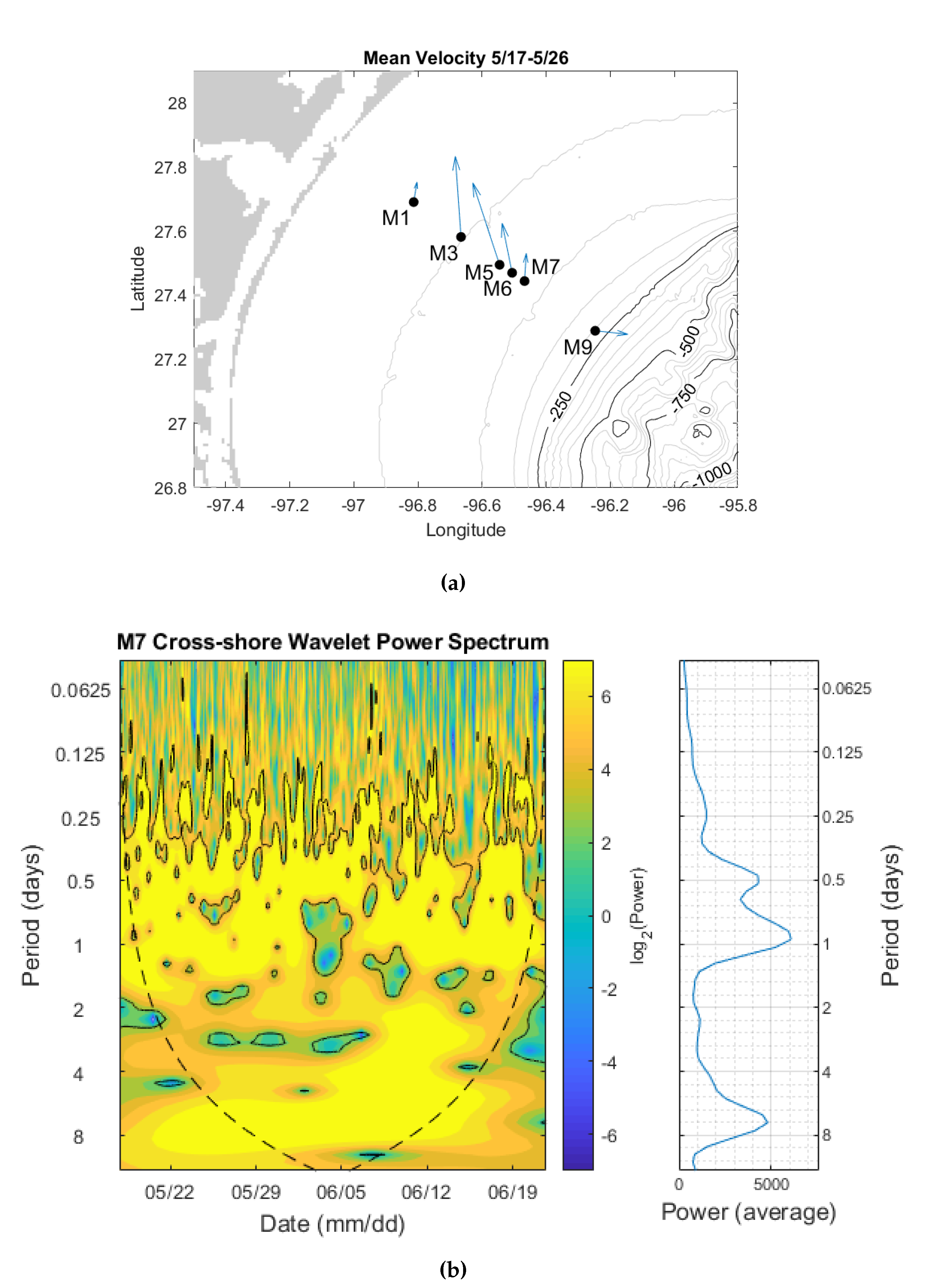
Here, we consider a unique dataset of bottom current measurements spanning late-May to mid-June 2016. This cross-topography array of SeaHorse tilt current meters (TCMs) was deployed between the 30 m and 200 m isobaths, although most instruments were concentrated in the 50–100 m depth range (
Figure 8a). Despite the relatively short duration of this deployment, the dataset captured flow that shares several key aspects with our transport model: an approximately 20 km wide, topographically controlled jet with peak velocity of approximately 7 cm/s is observed to be centered near the 50 m isobath. The jet is perturbed by a strong seven day oscillation (
Figure 8b) with an approximate amplitude of 10 cm/s, consistent with a bottom-intensified topographic Rossby wave (the spectrum in
Figure 8b was calculated for instrument M7 at 70 m depth but is representative of all observed spectra). The jet is also perturbed by a weaker (approximately 5 cm/s) higher frequency oscillation with a period of one day, consistent with a tidal signal (
Figure 8b). Note that, contrary to typical topographically controlled flows, which have shallow water to the right of the jet, here, the jet is reversed, with shallow water to the left, as is normal for the summertime Texas Shelf circulation. Furthermore, these observations are bottom current measurements taken 1 m off the bottom. Thus, the observed shoreward slant of the mean velocity vectors is possibly an Ekman spiral effect.
To model this particular flow, we use the following parameter values:
,
m,
,
m/s,
km,
m/s,
days,
m/s, and
day
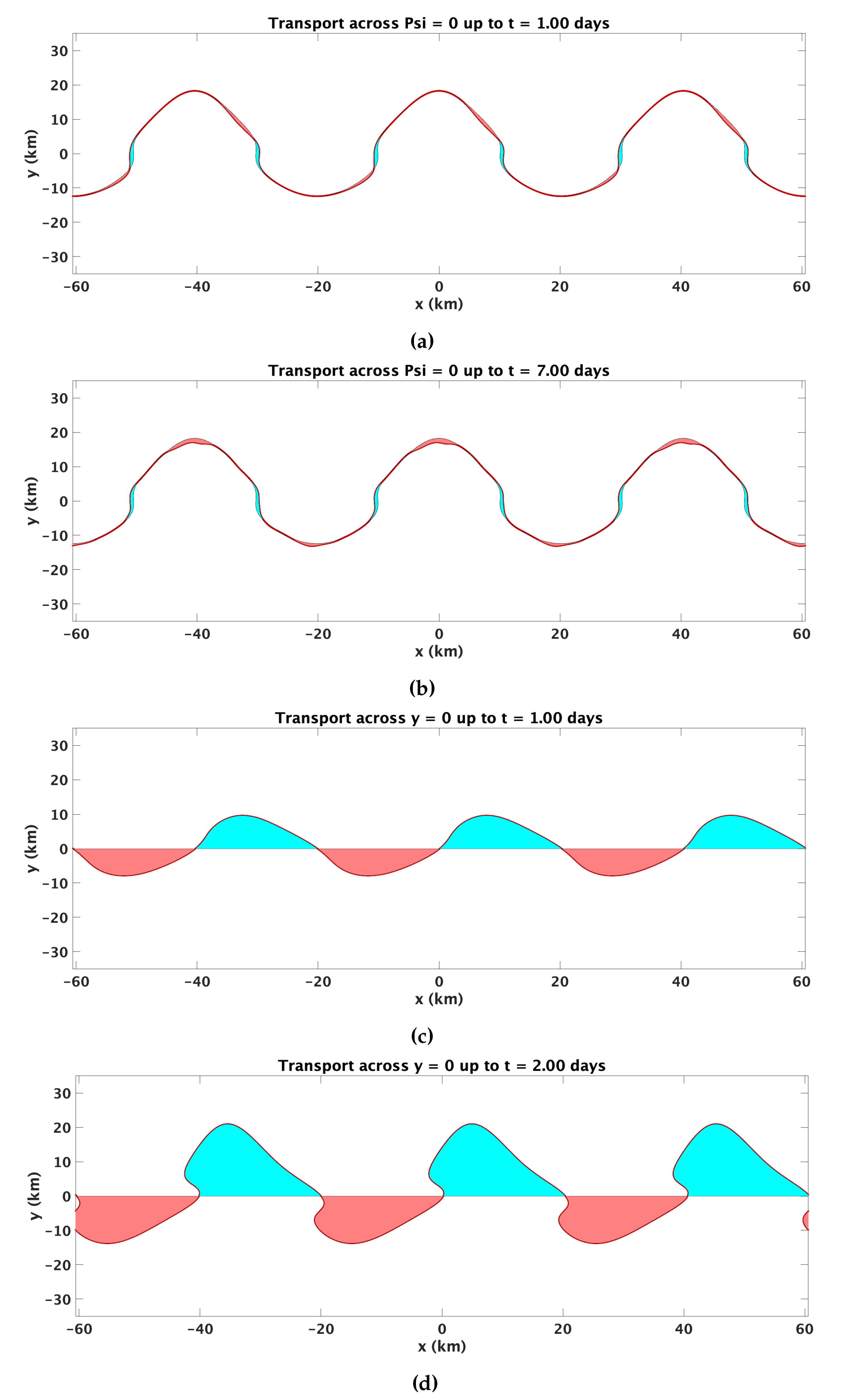
. After one tidal period, the transport across
consists of a per wavelength (
km) volume exchange of 0.38 km
(
Figure 9a). The transport occurs in small pockets along the edge of the
surface. Over one wave period (or seven tidal cycles), the transport increases, with a per wavelength volume exchange of 0.46 km
(
Figure 9b). This suggests there is potential for significant background cross-topography transport on the Texas Shelf under normal conditions even without eddy impingement.
We return now to the earlier observation that for practical applications, the transport across a fixed geographic boundary, such as an isobath, may be more relevant.
Figure 9c,d show the transport over
(the 50 m isobath) for one and two tidal periods, respectively. By this metric, onshore transport is even more substantial, at 5.55 km
after one day and 11.11 km
after two days.
6. Discussion and Conclusions
We presented a simple analytical model to analyze cross-shelf transport by generic shelf/slope dynamical processes. It consists of a linear superposition of a topographically controlled jet, a topographic Rossby wave, and a tidal oscillation. Despite its simplicity, the resulting transport characteristics are complex. Most importantly, the analysis demonstrates the potential for significant background cross-topographic transport under what are generally considered “normal” periodic shelf/slope conditions, without requiring the introduction of eddy impingement, frontal instabilities, or atmospheric forcing. In fact, the transport magnitude estimated here is comparable to that found in previous studies to result from eddy-shelf interactions [
1].
To further probe these transport characteristics, we explored the parametric dependence of the transport on several key system parameters , , and , whose definitions are designed to capture the main processes at work while relying on easily observable quantities. Due to the number of parameters involved in our model, the non-dimensional parameters chosen are not completely independent, but do illustrate how the trends in transport depend on these common ocean observables.
Each flow component independently will not result in any aperiodic cross-topography transport. The jet is directed along isobaths, and each individual oscillation is periodic, so particle trajectories will return to their initial position once every period. There is a slight drift due to the topographic slope, but that is not a significant factor. A combination of tidal oscillation and the Rossby wave will only produce reversible transport in a period that is a multiple of the two underlying periods. The combination of a tidal oscillation and a coastal jet will also result in particle trajectories that return to their initial depth contour (plus downstream advection) because the velocity components are orthogonal and the tidal signal is modeled as independent of location. It is the combination of the along-shore current with a spatially dependent cross-shore component that results in appreciable cross-topographic transport and consequent potential for mixing between coastal and open ocean water masses. Without the tidal component, however, that is in the case with only a jet and topographic wave, such transport across the
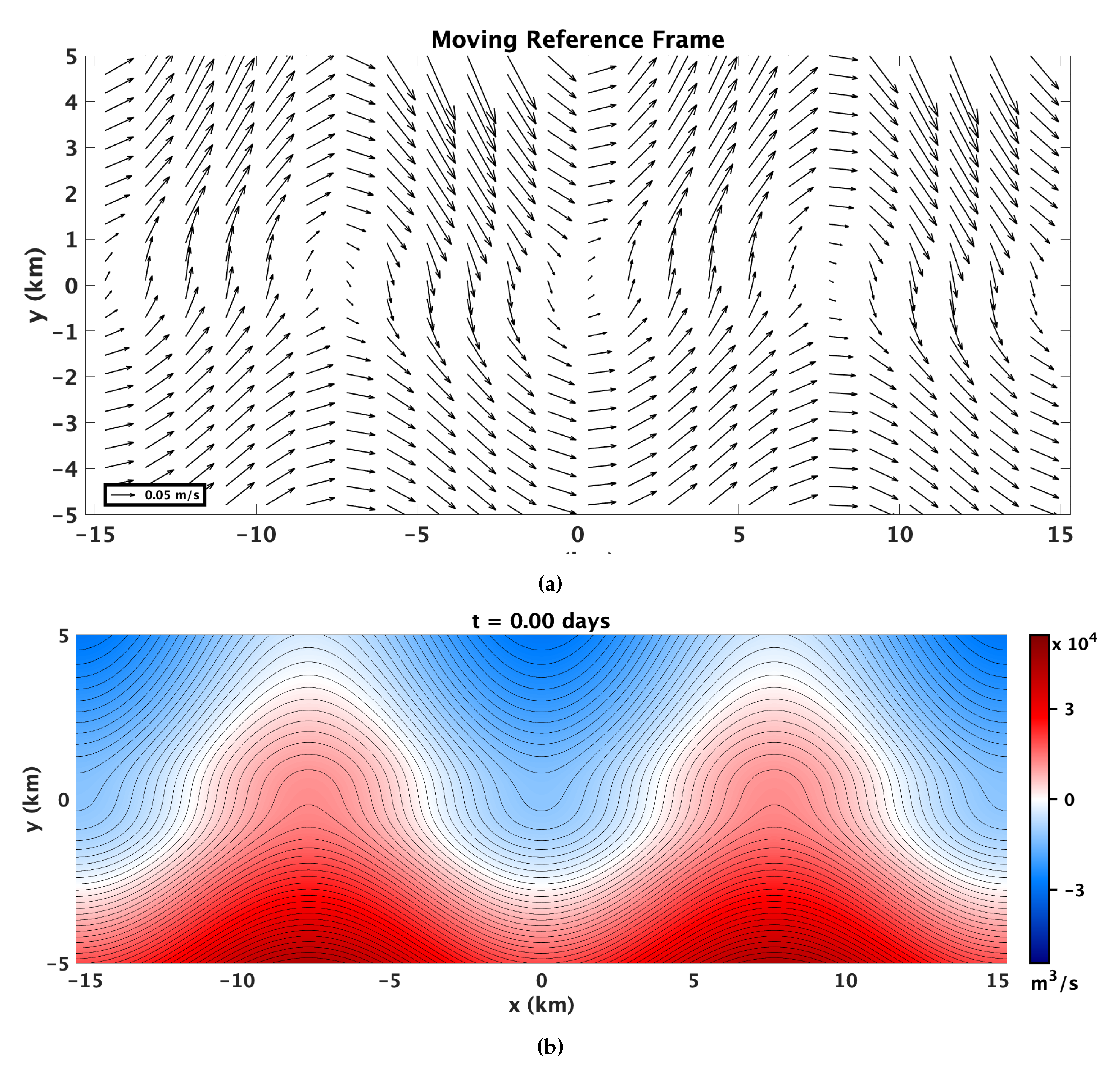
line is somewhat artificial: in the moving reference frame, the streamfunction is constant as in
Figure 2b, so that there is no cross-shelf transport across the
isoline. Thus, the combination of all three processes is necessary to produce true open coastal ocean mixing. As the tidal oscillation and stationary flow patterns are not orthogonal, there will be aperiodic transport. The effect is a time-dependent streamfunction field that is aligned with the relevant invariant manifolds only once per tidal cycle, as illustrated in
Figure 3, leading to particles not returning to their initial positions after a tidal or wave period (
Figure 4).
The transport volume is controlled by the interaction between the three processes with the topographic conditions. This is shown in the parameter sensitivity study. Parameter
considers the ratio of the topographic wave speed to the jet strength (
Figure 5). As the wave speed and jet speed get closer to balancing each other, the transport increases. This occurs since the jet and wave speed counteract each other, and when neither dominates, the strength of the barrier die to along-shore currents is weakened. Parameter
considers the ratio of the cross-shelf velocity advective length scale to the jet width (
Figure 6). A sweet spot was identified in which the cross-stream and along-stream advective components couple to result in a maximum transport. Parameter
considers the ratio of the shelf width to the jet width (
Figure 7). However, the secondary effects of accompanying changes in
and
were found to dominate. The impact of increased tidal strength was tested in addition to the non-dimensional parameters and found to be associated with increased transport.
As a specific example, a transport analysis for the Texas coast is presented, using parameters drawn from observational data. The key features of this observational dataset are a topographically controlled jet, a one day oscillation consistent with a tidal signal, and a seven day oscillation, consistent with a topographic Rossby wave. The application of our model to these observational conditions suggests that a significant amount of cross-topographic transport (open-ocean coastal-ocean mixing) can occur under normal shelf conditions. This has implications for larval distribution, oil spill response, and other coastal management issues, as the absence of eddies or density filaments will not guarantee isolation of on-shore and off-shore waters.
In summary, it was shown that there exists a fundamental background open ocean coastal-ocean connectivity pathway due to the interactions of a topographically controlled jet, a topographic Rossby wave, and a tidal oscillation. An analytic model of such systems was provided, and a parameter study was conducted to explore the sensitivity of transport to several key ocean observables. The application of the model to the Texas Shelf demonstrated significant transport and mixing potential under these basic flow conditions. The parameter space exploration suggests that this finding will vary across other regions of the ocean, but it also enables straightforward transport predictions based on a few observable characteristics. It is the authors’ hope that confirmation of this advective open-ocean coastal-ocean transport pathway will help inform coastal ocean management decisions and provide guidance for future field programs targeting coastal transport processes.
