3.1. Review of Flow Around Circular Cylinders
The inviscid solution to flow around a 2D circular cylinder [
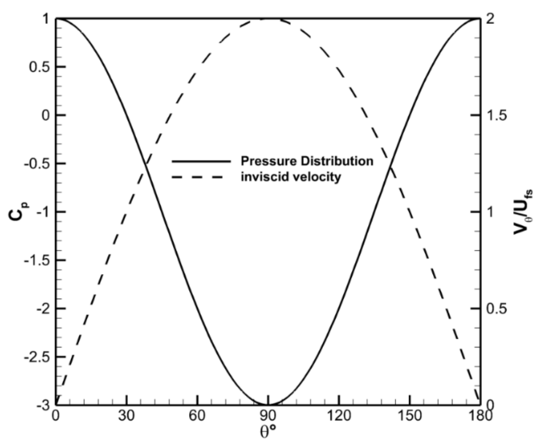
17] provides the limiting case for the current study. The solid line in
Figure 5 shows the surface pressure distribution, while the dashed line shows the associated tangential surface velocity,
Vθ, distribution for the inviscid flow around a cylinder. The leading edge of the cylinder is defined as
θ = 0°. In the absence of viscosity, the peak speed around a circular cylinder is
Vθ/Ufs = 2 and is located at
θ = 90°. This corresponds to a minimum pressure coefficient of
Cp,min = −3 at the same angular location. Equation (1) indicates that a factor of 2 increase in the wind speed would result in a factor of 8 potential increase in the harvestable power at the surface of the cylinder. It is worth noting that the actual increase in power would be lower than a factor of 8 as
Vθ decreases in the radial direction even for the inviscid case; therefore, the actual increase in power would depend on the radius of the wind turbine blades.
Past results for circular cylinders without end effects [
18,
19,
20,
21] show that for Reynolds numbers of practical importance, the flow separates and forms a wake downstream of the cylinder. The location of the separation generally begins at about
θ ≈ 70° and moves aft (i.e., increasing
θ) with the increasing Reynolds number to an angle of
θ ≈ 120°, as shown in
Figure 6. These results also show that the wake region becomes smaller with the increasing Reynolds number. The Re = 8.5 × 10
5 case shown in
Figure 6 does not follow the Reynolds number trends as
Cp,min is significantly lower and further aft for this case than for the higher Re = 3.6 × 10
6 case. This is due to the formation of a separation bubble at the surface of the cylinder, which occurs in a critical Reynolds number range [
18].
Results for finite aspect ratio cylinders with two free ends in the Reynolds number range of the current experiments are more limited as most studies are concentrated on cantilevered finite aspect ratio geometries [
22,
23,
24]. Zdravkovich et al. [
25] investigated the pressure distributions around circular cylinders of finite aspect ratio with two free ends for the Reynolds number between 0.6 and 2.6 × 10
5. Data from that work for a
L/D = 1 and Re = 2.6 × 10
5 showed
Cp,min ≈ −1.6 occurring at
θ ≈ 70°. The angular location of
Cp,min was consistent with the data from Achenbach [
18] with a difference of approximately 33% in
Cp,min. The work in this study is compared with the results of Achenbach to provide comparative analysis on the effect of the short aspect ratio on the pressure distribution.
3.2. Pressure Surveys
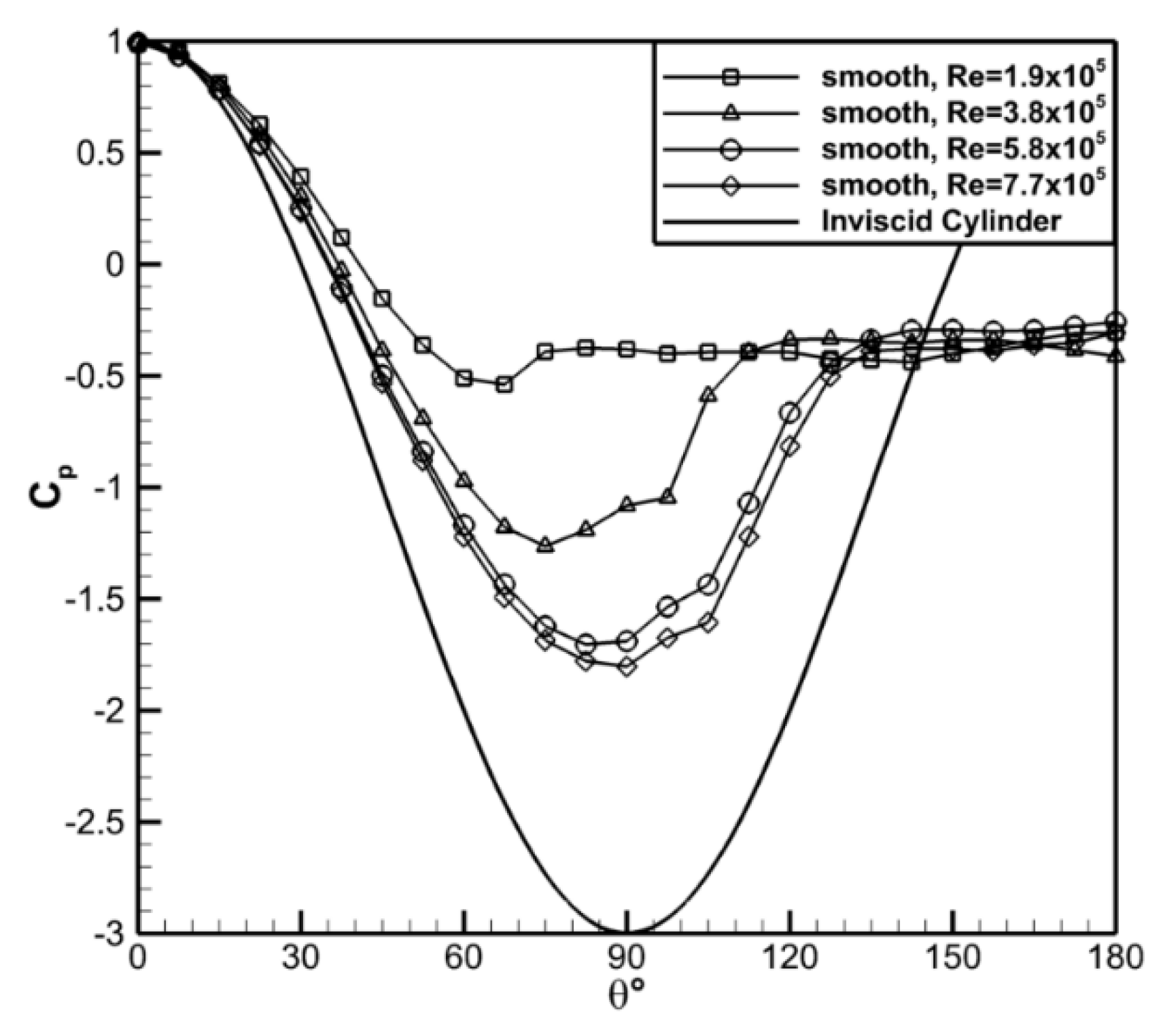
Figure 7 shows the surface pressure distribution along the centerline of the smooth cylinder for the Reynolds number range investigated. The data showed that
Cp,min decreased and its location moved aft as the Reynolds number increased, consistent with the trends for the 2D cylinder. At Re = 1.9 × 10
5 the surface pressure deviated almost immediately from the inviscid profile and had a minimum pressure coefficient of
Cp,min = −0.5 at
θ ≈ 68°. The pressure coefficient recovered slightly to a nominally constant value of
Cp = −0.4 after this point. The location and value of
Cp,min were indicative of laminar flow around a cylinder. For the Re = 7.7 × 10
5 case the minimum pressure coefficient was found to be
Cp,min = −1.8 at
θ ≈ 90°, more consistent with turbulent flow. The dependence on the Reynolds number appeared to be more significant at lower Reynolds numbers and was likely a result of the transition from laminar to turbulent flow.
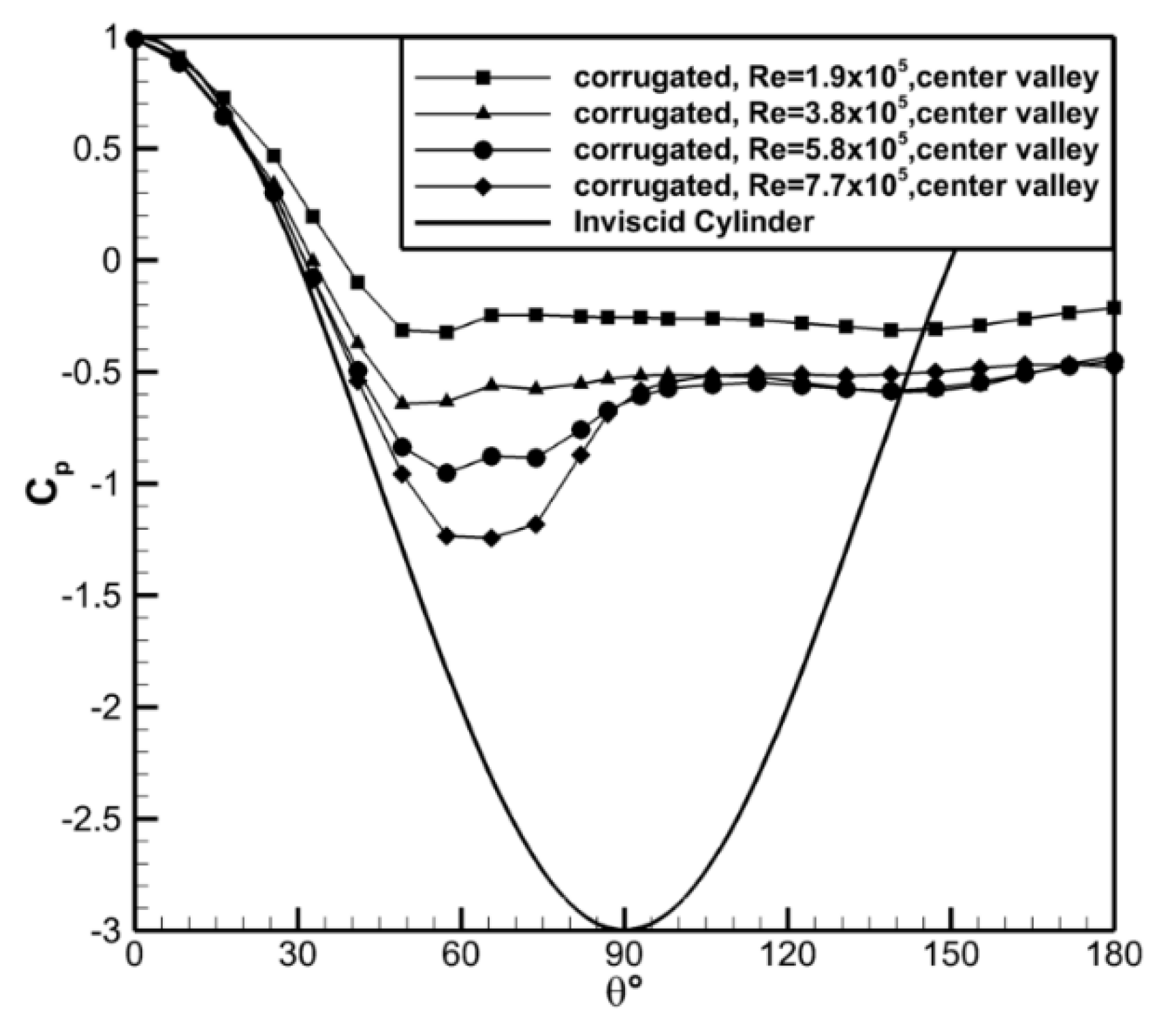
The results for the valley of the center channel for the corrugated cylinder are shown in
Figure 8. There was similar Reynolds number dependence observed for this model. The minimum pressure coefficient,
Cp,min, decreased with the increased Reynolds number going from
Cp,min ≈ −0.33 at Re = 1.9 × 10
5 to
Cp,min ≈ −1.24 at Re = 7.7 × 10
5. While the location of
Cp,min shifted farther aft on the cylinder with increasing Reynolds number (
θ ≈ 54 to 66°), this shift was less significant than was observed for the smooth cylinder. In the separated wake of the corrugated cylinder, the pressure coefficient was nominally uniform for all cases at
Cp = −0.52 except for the lowest Reynolds number case for which
Cp = −0.28 in this region. This case also showed very little pressure recovery after the location of the minimum pressure.
Comparison of the two current cases to previous data [
18] are shown in
Figure 9. The current data for the low aspect ratio smooth cylinder indicated that the pressure distribution was significantly altered by the lower aspect ratio of the model in the current study throughout the Reynolds number range investigated. Specifically,
Cp,min was lower and its location more aft for the infinite span compared to the finite span case. These observations indicated that end effects caused earlier separation, which reduced the pressure change on the cylinder surface. Data taken were also acquired with end plates (1.5
D) on the finite aspect ratio smooth cylinder. These plates were insufficient to counteract end effects at low Re, as can be seen in
Figure 9a; however, at the higher Re, shown in
Figure 9b, the surface pressure profiles are more similar to the reference data of Achenbach [
18]. The high Reynolds number cases for the current data and the reference data were both in the critical Reynolds number range with flow separation and reattachment; however, the gradient in the pressure distribution following separation was lower for the finite aspect ratio cylinder. This implied that the separation and reattachment region was likely smaller for the finite aspect ratio case in the critical Reynolds number range.
Comparison of the corrugated and smooth cylinders showed
Cp,min was significantly lower for the smooth cylinder when compared to the corrugated cylinder, as shown in
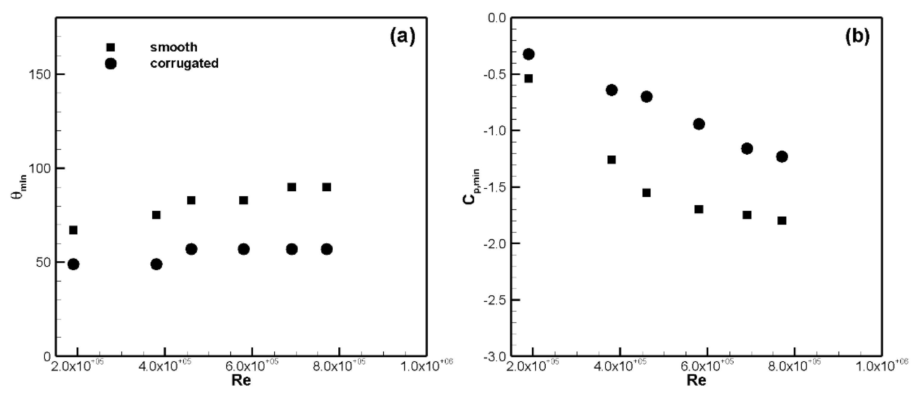
Figure 9. The location of the measured minimum pressure and the minimum pressure coefficient, to the spatial resolution of the current data, are shown in
Figure 10 to highlight the difference between the models. The location of the minimum pressure,
θmin, was earlier and the value of
Cp,min was higher for the corrugated cylinder versus the smooth cylinder. For example, at Re = 7.7 × 10
5 the values were −1.25 vs. −1.80 for
Cp,min and 57° vs. 90° for
θmin. The pressure surveys indicated that the separation was earlier for the corrugated model and was suggestive that the drag would be higher for case as well. Limited direct drag measurements, not shown in this work, measured a drag coefficient of
Cd = 0.95 for the corrugated cylinder compared to
Cd = 0.60 for the smooth cylinder at Re = 7.7 × 10
5 supporting the results of the pressure surveys. The higher relative
Cp,min values were suggestive that the flow speeds, and therefore the degree of flow acceleration, for the corrugated model were lower than for the smooth cylinder. This was important for the motivating accelerated wind application in that it indicated that the smooth cylinder would perform better. The trends in these results would be expected to hold for the real world application, which would include wind turbine blades, though the magnitudes would be expected to be different.
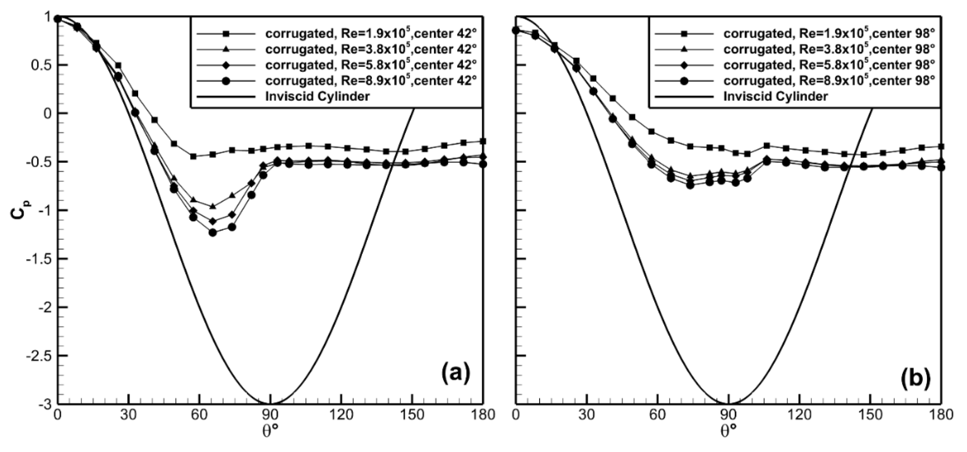
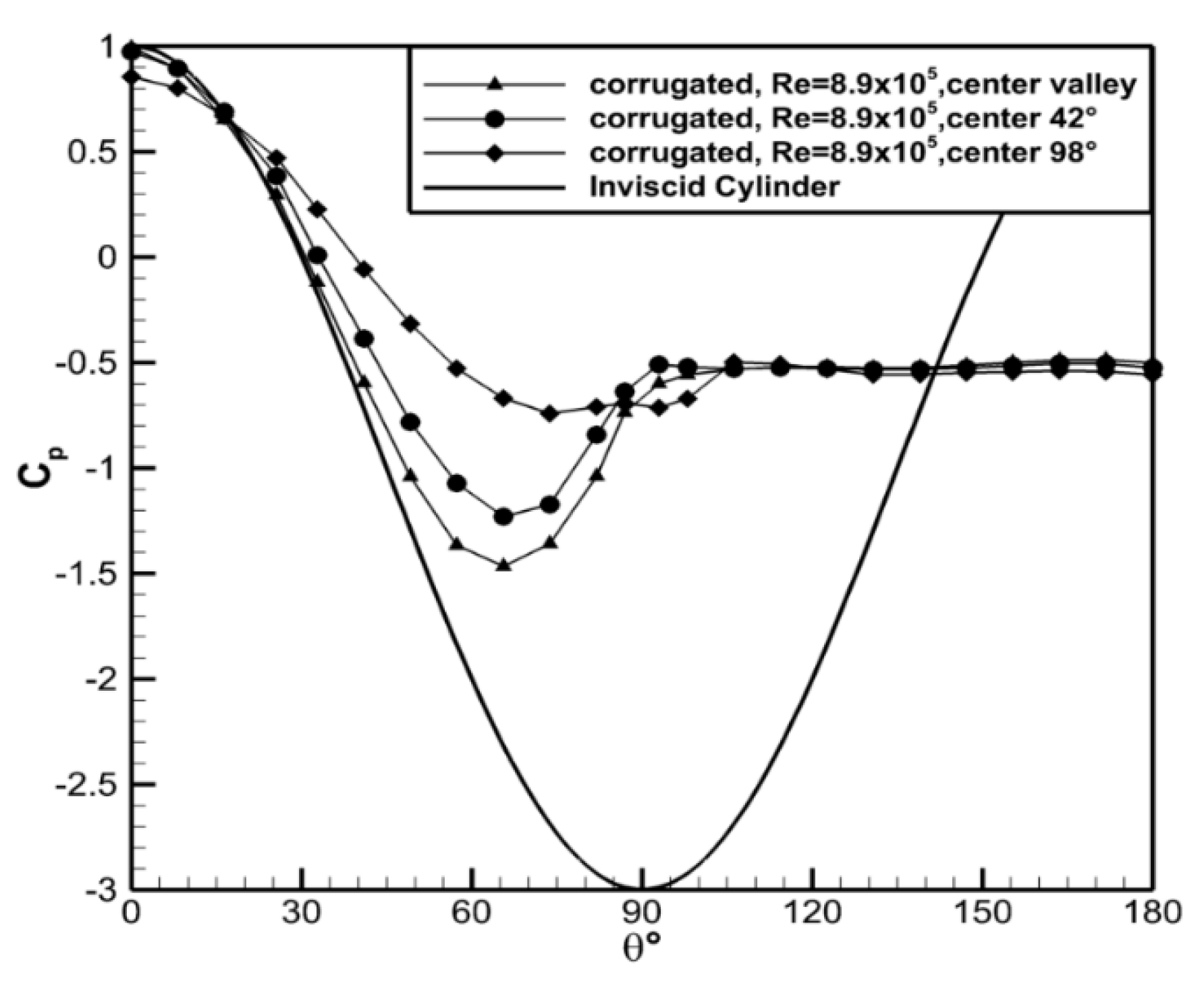
The surface pressures at
ϕ = 42°, 98° up the side wall of the corrugated cylinder model are shown in
Figure 11. The Reynolds number trends observed in the channel valley continued along the channel walls with
Cp,min decreasing with increasing Reynolds number. At
ϕ = 42° up the channel wall the location of
Cp,min moved from
θ ≈ 57° at Re = 1.9 × 10
5 to
θ ≈ 65° at Re = 3.8 × 10
5. Beyond this Reynolds number the separation point remained at nominally the same angular location. Similar trends were observed at
ϕ = 98° up the side wall. It is interesting to note that stagnation conditions,
Cp < 1 at
θ = 0, were not observed at the
θ = 98° location indicating the leading edge flow field was quite complex and three dimensional.
The pressure distributions along the sidewalls are compared in
Figure 12. The minimum pressure coefficient,
Cp,min, increased from
Cp,min = −1.46, in the valley, to
Cp,min = −1.23 at
ϕ = 42° and
Cp,min = −0.74 at
ϕ = 98°. The angular location of
Cp,min was the same for the valley and
ϕ = 42° but moved slightly further aft at the
ϕ = 98°. The pressure at the leading edge also showed a dependence on the wall location. In the channel valley,
Cp = 0.99 indicating that the tap was at or near a stagnation point. The pressure coefficient was slightly less than this (
Cp = 0.97) at
ϕ = 42°. In contrast, at
ϕ = 98°,
Cp = 0.85 for the leading tap. The data show that the flow approached stagnation conditions in or near the valley bottom. The pressure coefficients were uniform in the wake region. The magnitudes of
Cp show that the surface pressure was three dimensional within the channels. This is suggestive that the flow acceleration was most prominent in the valley region and decreased towards the side walls of the channel. Note that only a single Reynolds number is shown in
Figure 12 for brevity; however, the qualitative trends were consistent for all Reynolds numbers investigated.
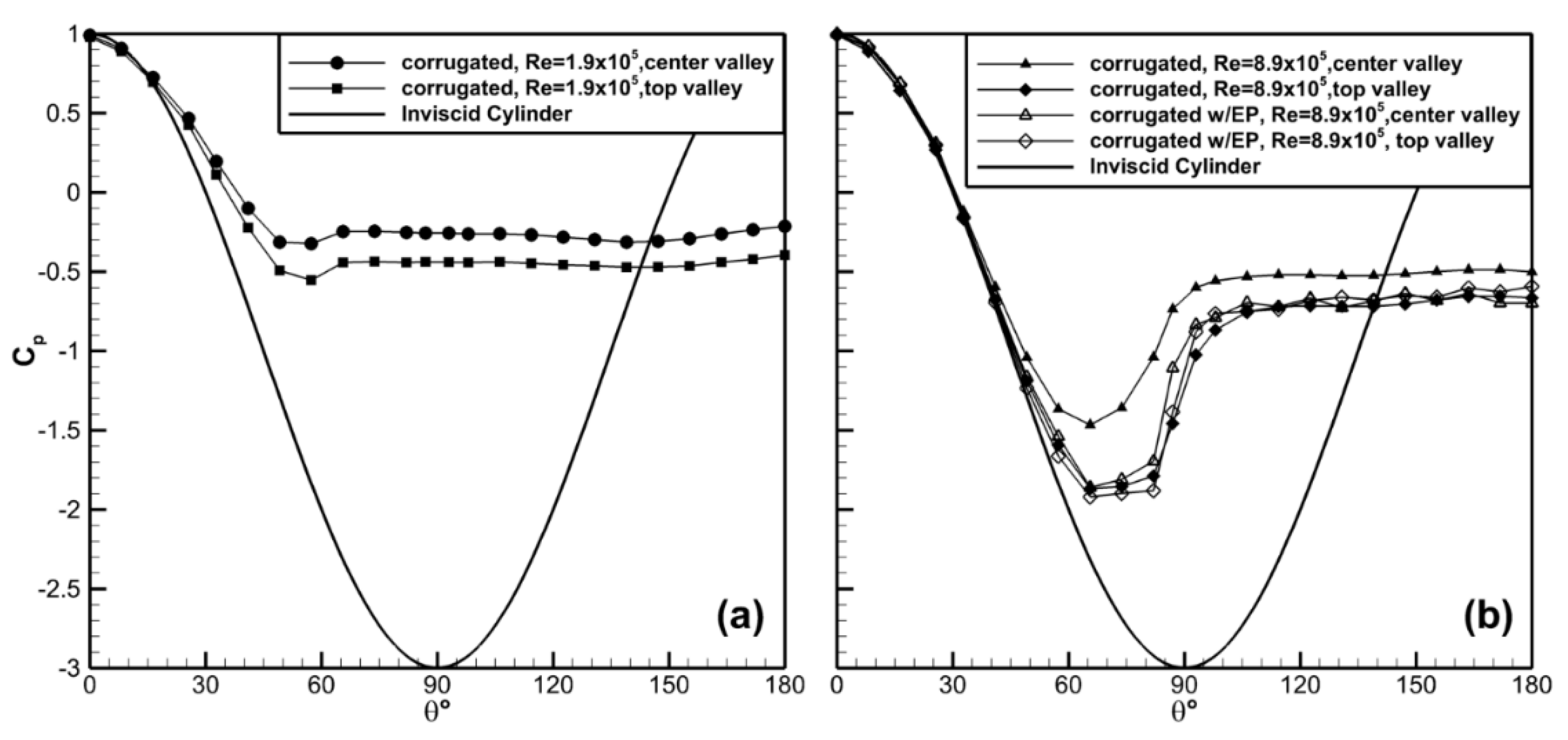
The corrugated cylinder had three channels along the axis of the model allowing for comparison of end versus interior channels. The pressure distribution in the valleys of the center (interior channel) and top channel (end channel) is shown in
Figure 13. Significant differences between the interior and end channels were observed. The end channel had lower
Cp values at all surface locations and for all Reynolds number cases indicating the end channels had higher potential for energy harvesting compared to interior channels. For example,
Cp,min = −1.86 for the top channel, and
Cp,min = −1.46 for the center channel at Re = 8.9 × 10
5. A similar trend was observed for the Re = 1.9 × 10
5 case with
Cp,min lower for the top channel (−0.55 vs. −0.32).
The difference between the two cases was caused by the channel boundary conditions, which were significantly different between the top and the middle channels. The interior channel had nominally symmetric boundary conditions due to the existence of channels above and below. The end channel had different boundary conditions on either side. The lower portion of the top channel was common with the upper portion of the center channel; however, the top portion of the upper channel was bounded by the free stream allowing air flow to go over top of the model. It was interesting to note that these end effects encountered by the top and bottom channels enhanced the performance of the flow dropping
Cp,min in the edge channels. The data suggested that the separation was delayed for the end channels resulting in the continued decrease in
Cp, which for the intended application would be beneficial. Data with end plates, shown in
Figure 13b, confirmed that end effects were responsible for the differences in the surface pressures in the center channel, though the end channel saw minimal improvement with the addition of the plates. The end plates did not appear to alter the pressure on the downstream side of the corrugated cylinder indicating that drag would likely continue to be high for this model.
3.3. Velocity Surveys
Velocity surveys were conducted with single-wire hot-wire probes around the smooth and corrugated cylinders. The probe was oriented at each angular location such that it measured the azimuthal velocity component, Vθ(r). The azimuthal velocity was of primary interest in this study as it is the velocity component normal to the intended rotor plane. Velocity surveys were conducted normal to the surface (i.e., in the radial direction) at 15° increments around the cylinder starting at the leading edge, θ = 0°. The data for the smooth cylinder were acquired at the mid-height of the cylinder, while the data for the corrugated cylinder were acquired along the center channel valley of the model. We note that both measurement locations were expected to have small relative spanwise velocity components due to the presence of the corrugations and/or symmetry. The radial velocity component was also expected to be small outside of the model wakes, which were beyond the expected placement of the rotors.
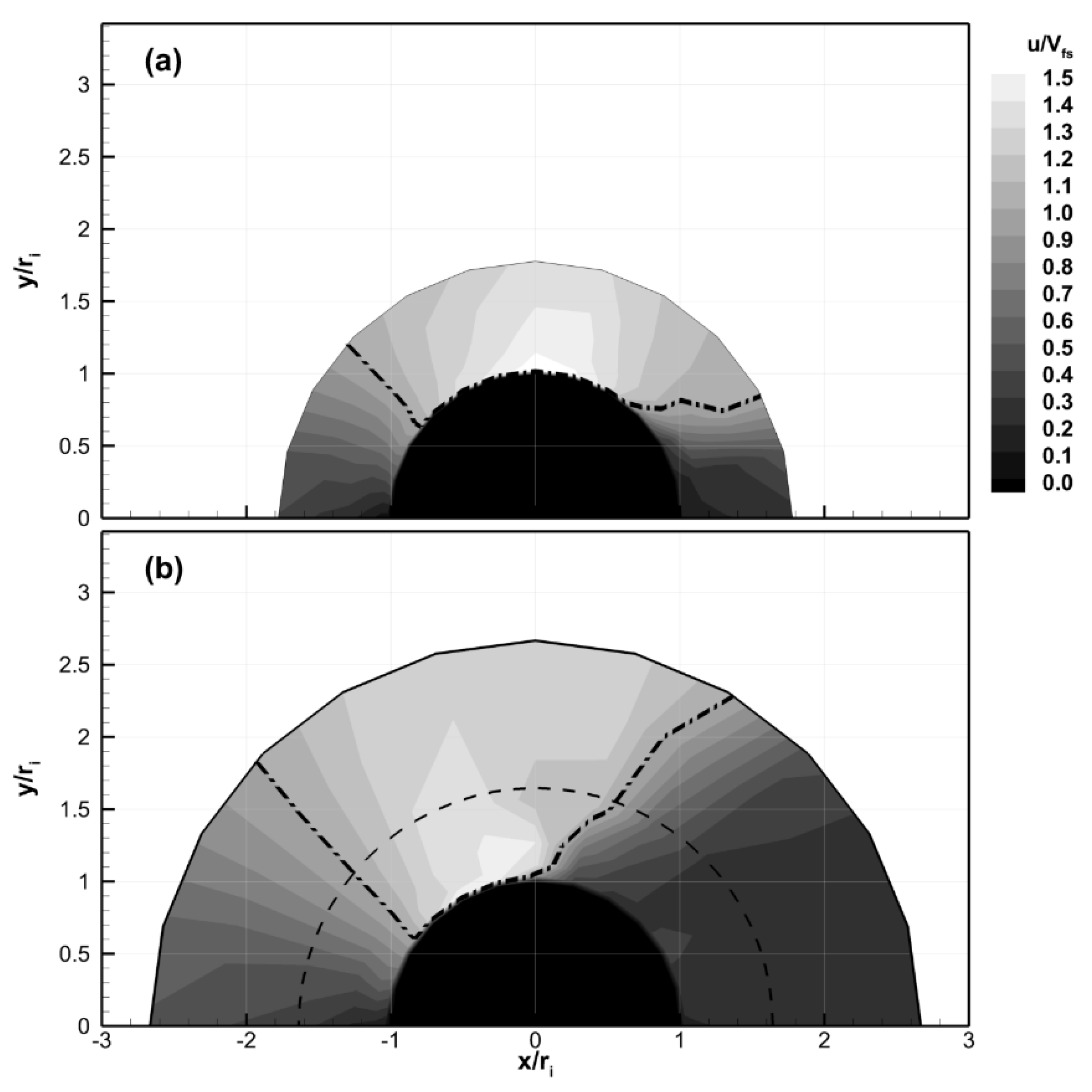
Results of the velocity surveys are shown in contour form in
Figure 14 for the Re = 7.7 × 10
5 case, which was closest to the expected operational Reynolds number. The dash-dot-dot line in the figure marks the boarder where the flow speed was equal to the free stream. This was included to differentiate the regions where the flow speed was either above or below the free stream value. Both cases show deceleration as the flow approached the leading edge, as expected. The flow then accelerated around both the smooth and corrugated cylinders; however, the velocity fields were quantitatively different for the two models. The data clearly show that the location of the peak flow speeds was shifted to higher angles (i.e., closer to
θ ≈ 90°) for the smooth cylinder. The peak speed for the smooth cylinder occurred at
θ ≈ 90° after which the flow decelerated, as shown in
Figure 14a. In contrast, the peak flow speed occurred earlier at
θ ≈ 75° for the corrugated cylinder model. The results also showed that the wake region, demarked by the region where the flow speed was below the free stream speed for the aft portion of the model, was physically larger for the corrugated cylinder. These observations were consistent with the pressure surveys, which showed lower
Cp values and more pressure recovery in the wake for the smooth cylinder. They are also consistent with the lower drag measurements for the smooth cylinder. It is noted that single hot-wire probes are not able to resolve the direction of the flow, only the magnitude, in the wake. As a result, the detailed structure of the wake region, e.g., where the flow could be reversed, cannot be determined from the current data.
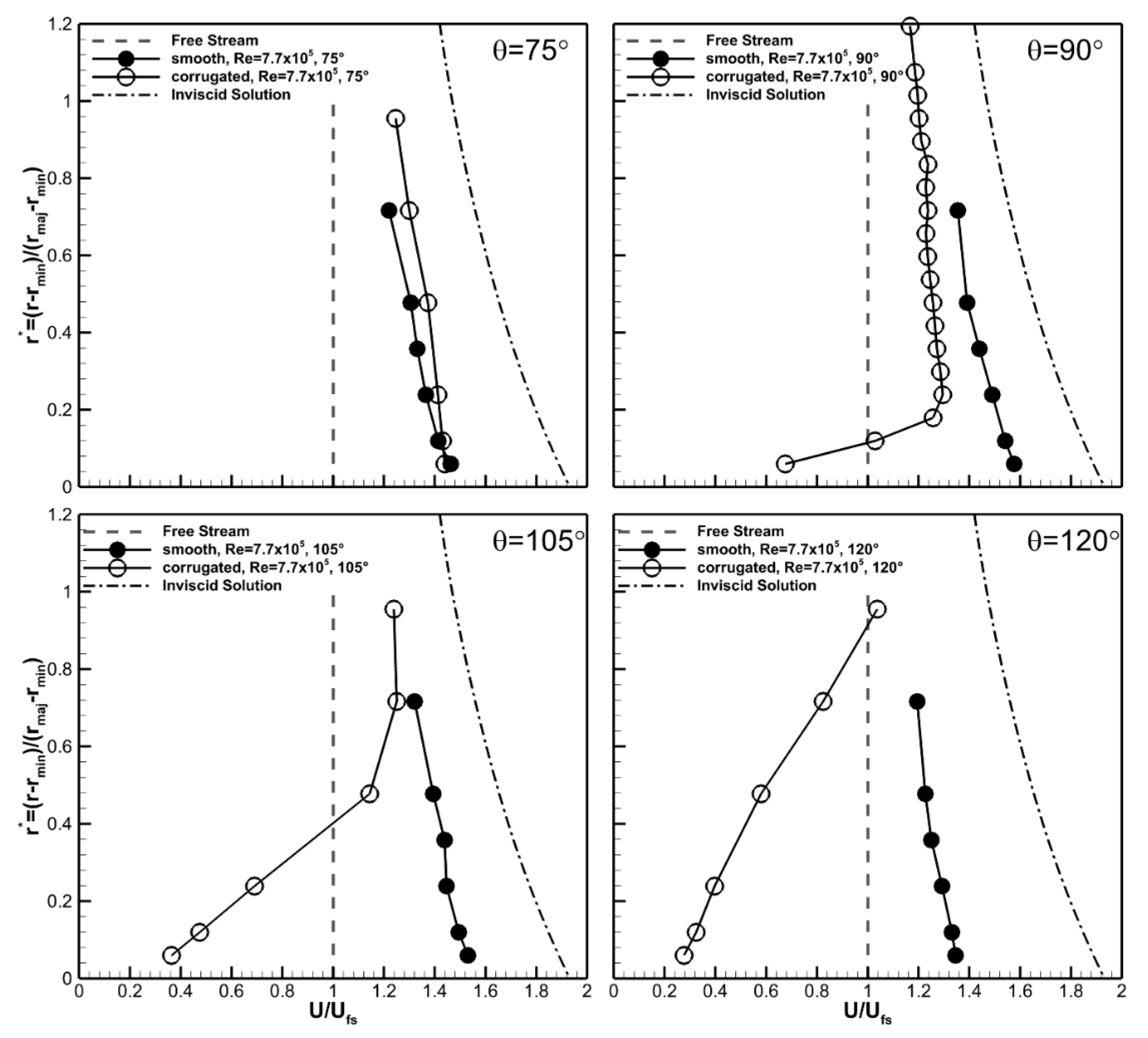
Velocity profiles at select angles are shown in
Figure 15 to quantify the differences between the velocity fields for the two cases. The radial distance was rescaled in
Figure 15 so that the model surface occurred at
r* = 0, and the distance was normalized by the difference in height between the major and minor axis of the corrugated cylinder. This scaling method resulted in
r* = 1 corresponding to the edge of the major diameter in the corrugated model and the equivalent dimensional distance for the smooth cylinder. The inviscid velocity profile at
θ = 90° (dash-dot) and free stream speed (dashed) are also plotted for reference in
Figure 15.
The velocity profiles were found to be qualitatively similar for the two geometries at θ = 75°. At this angular location the velocities were higher than the freestream at all radial measurement locations, with the highest value of Vθ/Vfs ≈ 1.43 at the measurement location closest to the surface. The velocity decreased to Vθ/Vfs ≈ 1.2 at the upper measurement location and appeared to be asymptotically approaching the freestream value. The boundary layer at the cylinder surface was relatively thin with a thickness less than the distance from the wall to the first measurement point at r* = 0.06.
At 90° the velocity profiles were qualitatively different for the two geometries. The flow around the smooth cylinder continued to accelerate due to the curvature of the wall. Velocities were higher at all radial locations compared to the 75° location for this geometry, and the boundary layer remained comparatively thin. The maximum value of the angular velocity was Vθ/Vfs ≈ 1.6, which was approximately 20% lower than the inviscid velocity of Vθ/Vfs ≈ 2.0. The corrugated cylinder showed a qualitatively different profile at this angular location. The changes in the structure of the velocity profile were most pronounced near the wall. The location of the peak velocity moved away from the wall forming what appeared to be a thick viscous boundary layer that occupied approximately 20% of the channel height. This resulted in a noticeably less uniform velocity profile, particularly near the wall. Additionally, the flow speed was lower than the freestream for approximately the bottom (i.e., near wall) 10% of the channel height. The flow speeds were comparatively lower at all locations than were measured at θ = 75° indicating the flow was decelerating within the channel.
These trends in the velocity data continued at θ = 105°. Here the velocity profile for the smooth cylinder was nominally the same as it was at θ = 90°, though the velocity magnitudes were slightly reduced. Comparison showed a slight deceleration in the velocity for the entire profile; however, this was expected due to the change in curvature of the model. The viscous boundary layer remained thinner than the data spacing. The low speed region of the corrugated cylinder continued to expand out away from the valley wall filling the bottom 60% of the channel height. Flow speeds lower than the free stream were measured in the bottom 40% of the channel height. By 120° the velocity magnitude was below the free stream in 80% of the corrugated channel height. The velocities also continued to decrease for the smooth cylinder, though they were still above the freestream value at all measurement locations. The velocity data were suggestive that viscous effects, likely due to the increased surface area of the corrugated cylinder, were responsible for the differences in the velocity and pressure results observed for that model.
Recall that the purpose of placing wind turbine blades next to a surface is to increase the kinetic energy of the wind before it enters the wind turbines blades. Ideally, one would prefer the flow speeds to be as high as possible (to maximize energy harvest) and uniform across the blades (for structural reasons). The experimentally measured and the computed inviscid velocity profiles were used to provide an estimate of the kinetic energy flux per unit width by:
It is acknowledged that the flow field varies in two dimensions (i.e., in the r-z plane) at a particular θ location for the two experimental geometries and that the actual kinetic energy flux over an area would differ from the integrated values using Equation (3). However, the estimate from this 1D integration provided a quantitative comparison of the geometries with the current data.
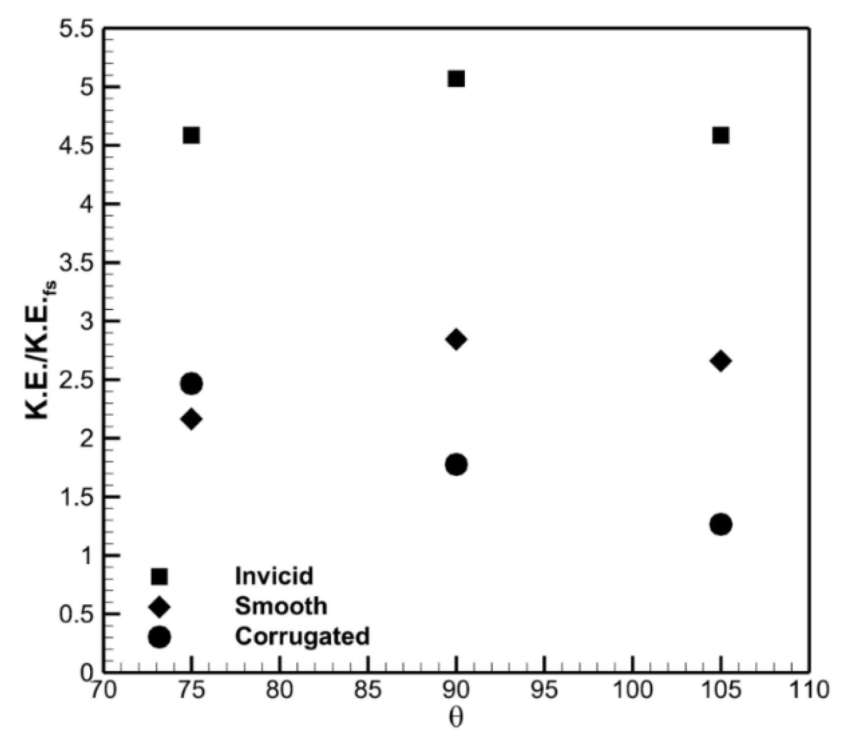
The inviscid profile provides a maximum of 5 times the kinetic energy in the free stream at
θ = 90°, as shown in
Figure 16. This is less than the “8 times” value because the inviscid velocity distribution varies with
r as previously discussed. The smooth cylinder also showed a peak normalized kinetic energy at
θ = 90°, though it was lower than for the inviscid flow (2.8 vs. 5). This result highlights the importance of the cubic functionality of the power with velocity. The corrugated cylinder had a maximum normalized kinetic energy at
θ = 75° and was comparable in magnitude (~2.5) to the smooth cylinder at this location. The normalized kinetic energy decreased for the corrugated cylinder at
θ = 90° and was lower than for the smooth cylinder case (1.7 vs. 2.8) and less than half of the inviscid case.
It is instructive to note that while both model cases were significantly below the inviscid kinetic energy potential, they were both above that for a rotor alone in a free stream (i.e., a value of 1). This indicated that the rotors could potentially experience enhancement due to placement next to both models. Interpretation of the values for the corrugated cylinder should be done carefully as the channel pressure and velocity data were suggestive that the velocities near the bounding walls would be lower than in the centerline of the channel. One should therefore expect that the kinetic energy flux (i.e., the area integrated KE flux) in the corrugated cylinder would be lower than what was calculated using Equation (3).
The turbine blades for the real-world application are best placed at θ = 90° for operational reasons. These reasons include the ability to self-align with the changes in the wind direction due to forces on the symmetrically placed pairs of rotor blades and the need for the system to be aligned out of the wind if needed. This azimuthal position therefore deserves additional discussion. Comparison of the data at θ = 90° clearly shows that the smooth cylinder had both higher velocities and a more uniform velocity profile. Uniformity in the velocity profile is desirable for blade loading and structural reasons in an accelerated application. In particular, the variation in the velocity profile measured for the corrugated model near the wall, approximately 50%, represents a potential difficulty if used as the loading near the tip varies significantly. The smooth cylinder on the other hand experiences a smaller fractional change, approximately 12%, across the blades. The lower velocities for the corrugated cylinder resulted in a 38% drop in the kinetic energy potential for the corrugated cylinder at this angular location. The results clearly showed that the smooth cylinder was a more desirable platform shape for the larger project.
