Article

Instability of a Diffusive Boundary Layer beneath a Capillary Transition Zone

by
Fengyuan Zhang
and
Hamid Emami-Meybodi
*
Department of Energy and Mineral Engineering and EMS Energy Institute, The Pennsylvania State University, University Park, PA 16802, USA
*
Author to whom correspondence should be addressed.
Fluids 2018, 3(4), 85; https://doi.org/10.3390/fluids3040085
Submission received: 18 October 2018 / Revised: 25 October 2018 / Accepted: 29 October 2018 / Published: 31 October 2018
(This article belongs to the Special Issue Fundamentals of CO2 Storage in Geological Formations)

Abstract

:
Natural convection induced by carbon dioxide (CO2) dissolution from a gas cap into the resident formation brine of a deep saline aquifer in the presence of a capillary transition zone is an important phenomenon that can accelerate the dissolution process, reducing the risk of CO2 leakage to the shallower formations. Majority of past investigations on the instability of the diffusive boundary layer assumed a sharp CO2–brine interface with constant CO2 concentration at the top of the aquifer, i.e., single-phase system. However, this assumption may lead to erroneous estimates of the onset of natural convection. The present study demonstrates the significant effect of the capillary transition zone on the onset of natural convection in a two-phase system in which a buoyant CO2 plume overlaid a water-saturated porous layer. Using the quasi-steady-state approximation (QSSA), we performed a linear stability analysis to assess critical times, critical wavenumbers, and neutral stability curves as a function of Bond number. We show that the capillary transition zone could potentially accelerate the evolution of the natural convection by sixfold. Furthermore, we characterized the instability problem for capillary-dominant, in-transition, and buoyancy-dominant systems. In the capillary-dominant systems, capillary transition zone has a strong role in destabilizing the diffusive boundary layer. In contrast, in the buoyancy-dominant systems, the buoyancy force is the sole cause of the instability, and the effect of the capillary transition zone can be ignored. Our findings provide further insight into the understanding of the natural convection in the two-phase CO2–brine system and the long-term fate of the injected CO2 in deep saline aquifers.

1. Introduction

Carbon dioxide (CO2) storage in deep saline aquifers is one of the mitigation options to achieve stabilization of CO2 concentration in the atmosphere. After injection of CO2 into deep saline aquifers, CO2 moves upwards due to the density contrast between the injected CO2 and the resident brine and spreads horizontally under a cap-rock as a separate free-phase. Over time, CO2 gradually diffuses downwards into the resident brine, creating a diffusive boundary layer just beneath a capillary transition zone. This dissolution increases the density of brine, bringing the system to a gravitationally unstable state, which results in natural convection [1]. Such convective mixing increases the rate of dissolution and therefore decreases the likelihood of CO2 leakage. Thus, understanding the fundamental characteristics of natural convection induced by CO2 dissolution is crucial to estimate the capacity and security of CO2 storage.
Most of the previous studies considered a single-phase system subject to an impermeable boundary condition at the top of the domain. This simplification neglects the presence of a capillary transition zone that normally exists between the gas cap and the underlying brine in a porous medium. However, the capillary transition zone allows vertical flow across the interface between the capillary transition zone and the diffusive boundary layer, affecting the onset of the natural convection. The effects of the capillary transition zone on the onset of convection have been studied by considering either a permeable upper boundary condition in a single-phase system [2,3,4,5] or a transition zone in a two-phase system [6,7,8]. These studies demonstrated that the capillary transition zone could potentially decrease the onset time of instability by threefold [5], fivefold [4], or even sixfold [6,8]. Accordingly, the capillary transition zone is expected to play a significant role in the instability of the diffusive boundary layer.
In this study, we further examined the effect of the capillary transition zone on the onset of instability and natural convection by extending the linear stability analysis (LSA) presented in [6,8] to remove three assumptions. First, we considered a three-dimensional, two-phase (gas and water), two-component (CO2 and H2O) physical system with Darcy’s velocities in x-, y-, and z-direction instead of using two-dimensional stream function equations. Second, we included the variation of relative permeability as a function of distance in the flow equation (i.e., Equation (12) in [6] and Equation (13) in [8]). As demonstrated in the next section, this consideration results in the addition of a saturation term to the stability equation for the perturbed velocity, i.e., Equation (24). Third, we took account of the variation of water-phase density due to CO2 dissolution in the saturation equation (i.e., Equation (13) in [6] and Equation (14) in [8]), which was neglected in the previous studies [6,8]. As discussed in the subsequent section, this consideration would add five terms to the stability equation for perturbed saturation, i.e., Equation (25).
The rest of this paper is structured as follows. Section 2 describes the conceptual model and presents the governing equations and the boundary conditions used to carry out linear stability analysis. This section also provides the details of linear stability analysis. Section 3 discusses the results of the linear stability analysis and shows the destabilizing effect of the capillary transition zone. Section 4 summarizes the main conclusions of this work.

2. Methodology

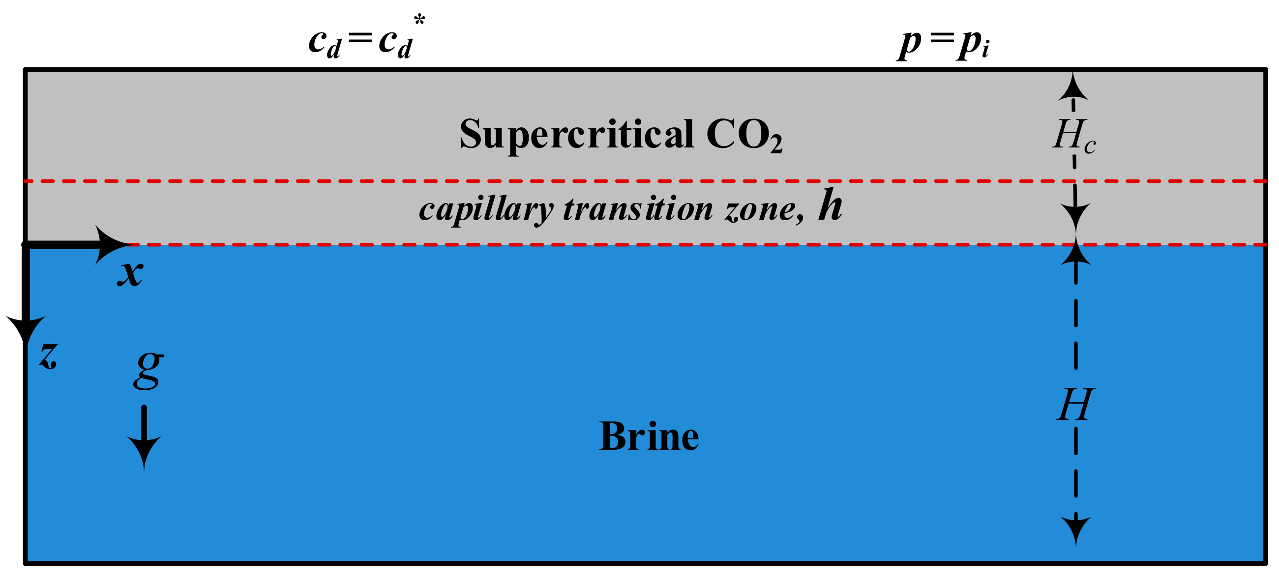
2.1. Conceptual Model

It is known that the time scales for diffusion and natural convection to become significant are typically much longer than the time for the CO2 injection period and the establishment of a thin CO2 plume beneath the caprock. Even for a CO2 plume migrating updip slowly, local CO2 saturation typically stabilizes much more quickly (e.g., hours to days) than natural convection can be established (e.g., years to decades). Thus, one can assume that CO2 distributes in a thin plume of constant thickness (Hc) spread beneath the caprock, and the processes creating CO2 distribution, such as Ostwald ripening or coarsening [9,10,11,12], are faster than CO2 diffusion in brine and the subsequent natural convection.
Accordingly, we considered a two-phase (i.e., water and gas), two-component (i.e., H2O and CO2) system where supercritical CO2 diffuses into the underlying porous layer saturated with water (see Figure 1). The porous layer is non-deformable, isotropic, and homogeneous with a thickness of H + Hc, where Hc and H are CO2 cap and water region thickness, respectively. We assumed that gravity–capillary equilibration establishes a capillary transition zone with a height of h between CO2 plume (i.e., part of Hc) and the water region with the thickness of H. We neglected the impact geochemical reactions that could control natural convection [13]. Furthermore, we assumed that the Boussinesq approximation [14] is valid because the density of aqueous solutions of CO2 is just slightly (about 1–3%) higher than pure water density [15].
As shown in Figure 1, a Cartesian coordinate system was chosen, in which the x-axis was the direction of the background flow, and the z-axis was oriented vertically downward in alignment with gravity. The lower boundary of the domain was considered to be impermeable with zero mass flux, and the upper boundary was maintained at constant pressure (p = pi) and concentration (cd = cd*). At time zero, the domain was free of solute concentration (cd = 0).

2.2. Governing Equations

The governing equations to describe the two-phase system are given by the multiphase extension of Darcy’s law, the convection–diffusion equation, and the continuity equations [16,17]:
v l = k k r l μ l ( p l ρ l g z ) ,   l   =   g ,   w ,
ϕ t l = g , w s l ρ l c d l = l = g , w ( v l c d l ϕ s l D 0 l c d l ) ,
ϕ t l = g , w s l ρ l + l = g , w ρ l v l = 0 ,
which are constrained by the following relations
s g + s w = 1 ,
p c = p g p w ,
where v = [u,v,w] is the Darcy velocity vector; u, v, and w are the velocity component in x-, y-, and z-direction, respectively; μ is the viscosity; k is the absolute permeability; kr is the relative permeability; p is the fluid pressure; pc is the capillary pressure; ρ is the density; g is the gravity acceleration; ϕ is the porosity; t is the time; s is the saturation; cd is the concentration of diffusive species CO2; D0 is the effective diffusion coefficient (i.e., the combination of the bulk diffusion coefficient and tortuosity effects, which are assumed to be constant); and subscripts w and g denote water and gas phase, respectively.
We assumed that the water-phase density, ρw, is a linear function of the local concentration of dissolved CO2, cdw [18]:
ρ w = ρ w 0 ( 1 + b c c d w ) ,
where b c = ( 1 / ρ w ) ρ w / c d w and ρw0 is the density of water at cdw = 0.
The capillary pressure is a function of the water-phase saturation and can be obtained from the Leverett J-function, which is a widely-used model for fitting the experimental data [19]:
J ( s w ) = p c ( ρ 0 w ρ g ) g h = k ϕ p c cos θ ,
where is the surface tension between the gas and water phase and θ is the contact angle between the fluid interfaces and the rock surface. We used the height of capillary pressure, h ~ cos θ / ( ρ w 0 ρ g ) g k / ϕ , as a measure of the capillary force because it is a function of the same parameters that shape the capillary pressure curves and is independent of the initial pressure.
Brooks–Corey [20] and van Genuchten–Mualem [21] models are two commonly used empirical models for relative permeabilities and capillary pressure curves, which behave differently for entry of the non-wetting phase into pores. The Brooks–Corey model forms a convex curve and reaches a plateau that ends with a nonzero capillary entry pressure, while the van Genuchten–Mualem model forms an S-shaped curve with a steep slope that connects to the endpoint, which is usually zero. Natural convection is expected to be stronger and occur faster with the van Genuchten–Mualem model since it provides a significant water zone with the same permeability as the single-phase water zone, but that is saturated with dissolved CO2 [22]. We adopted the van Genuchten–Mualem model for the relative permeabilities and capillary pressure constitutive relations [21,23]:
k r g = ( 1 S ) 1 3 ( 1 S 1 m ) 2 m ,   k r w = S 1 2 ( 1 ( 1 S 1 m ) m ) 2 ,   J = ( S 1 m 1 ) 1 n ,
where S = (sswr)/(1 − swr) and is the dimensionless saturation; swr is the residual saturation of the water phase; and n is the material parameter with m = 1 − 1/n. Although n > 1, we used n ≥ 2 because the van Genuchten–Mualem model yields unrealistic curves if n < 2 [24].
For analytical purposes, the governing equations were non-dimensionalized by choosing diffusion length, Lc = D0φ/ub, as the length scale with φ = ϕ(1 − swr), ub = kgbcρw0 c d * /μw as the buoyancy velocity, and D0/ L c 2 as the time scale. Accordingly, the dimensionless time and space parameters are
t D = D 0 L c 2 t ,   x D = x L c ,   y D = y L c ,   z D = z L c ,
and dimensionless concentration and velocity are
C = c c d * ,   U = u u b ,   V = v u b ,   W = w u b ,
where cd* is the maximum solubility of CO2 in water at the reservoir pressure and temperature.
For linear stability analysis (LSA), a semi-infinite domain was considered in z-direction because, at early times, when the diffusive boundary layer is very small, the domain behaves as a semi-infinite medium in z-direction and an infinite domain in x- and y-direction. The capillary transition zone combined with the underlying water phase region was considered as the domain of study. In addition, a self-similar coordinate was chosen by applying ξ = z D / τ transformation to localize the diffusion operator around the front and achieve a considerable improvement in accuracy at early times. The dimensionless form of the governing equations for flow, saturation of water phase, and transport can be expressed:
2 W x D 2 + 2 W y D 2 + 1 τ 2 W ξ 2 k r w ( 2 C x D 2 + 2 C y D 2 ) k r w ( S x D C x D + S y D C y D ) k r w k r w ( W x D S x D + W y D S y D + W ( 2 S x D 2 + 2 S y D 2 ) + 1 τ S ξ W ξ 1 τ ( U 2 S x D ξ + V 2 S y D ξ ) ) ( k r w k r w ) ( W ( ( S y D ) 2 + ( S x D ) 2 ) 1 τ S ξ ( U S x D + V S y D ) ) = 0 ,
S τ ξ 2 τ S ξ f f ( U S x D + V S y D + W τ S ξ ) + G B o f ( ( k r g J ) ( ( S x D ) 2 + ( S y D ) 2 + 1 τ ( S ξ ) 2 ) + k r g J ( 2 S x D 2 + 2 S y D 2 + 1 τ 2 S ξ 2 ) ) + 1 f τ ( k r g C ξ + k r g ( C + G ) S ξ ) = 0
S C τ S x D C x D S y D C y D 1 τ S ξ C ξ + U C x D + V C y D + W τ C ξ S ( 2 C x D 2 + 2 C y D 2 + 1 τ 2 C ξ 2 + ξ 2 τ C ξ ) = 0
which are subject to the following boundary conditions:
W = V = U = 0 ,   S = 0 ,   and   C = 1   at   z D = 1 B o ,
W = V = U = 0 ,   S = 1 ,   and   C = 0   at   z D ,
where f = μgw + krg/krw and primes denote derivatives with respect to the water-phase saturation.
According to Equations (11)–(13), the two-phase system under consideration can be explored with the following dimensionless groups:
B o = L c h   ( Bond   number ) ,
n = 1 1 m   ( material   parameter ) .
Although the gravity number, G = k(ρw0ρg)g/ubμw, and the viscosity ratio, M = μgw, appear in the formulations, they do not affect the instability of the two-phase system because the denser water with the higher viscosity is located under the lighter CO2 with the lower viscosity [25,26]. The Bond number is a measure of the relative strength of gravitational forces to capillary forces where the limit Bo → ∞ recovers the single-phase system in which h → 0. The material parameter n is a measure of the pore-size distribution that depends on the degree of sorting of the grains in a porous medium.
From Equations (11)–(15), the base-state solutions for velocity components (U0, V0, and W0), saturation (S0), and concentration (C0) can be expressed by:
W 0 = V 0 = U 0 = 0 ,
S 0 ( ξ ) = 1 + Η ( ξ ) ( ( 1 + ( υ B o τ ξ ) n ) 1 n n 1 ) ,
C 0 ( ξ ) = 1 Η ( ξ ) e r f c ( ξ 2 ) ,
where H is the Heaviside step function and υ is a constant that ensures sw = swr at z = −h, which should be assigned according to the value of n.

2.3. Linear Stability Analysis

To conduct an LSA, small disturbances of velocities U1, V1, and W1, saturation S1, and concentration C1 were introduced; therefore, U, V, W, S, and C can be written as:
{ U , V , W , S , C } ( x D , y D , ξ , τ ) = { U 0 , V 0 , W 0 , S 0 , C 0 } ( ξ , τ ) + ε { U 1 , V 1 , W 1 , S 1 , C 1 } ( ξ , τ ) e i ( a x x D + a y y D )
where i = 1 and ax and ay are the dimensionless wavenumber in x- and y-direction, respectively, with a very small amplitude ε. The subscripts 0 and 1 represent the base and disturbance quantities, respectively.
To eliminate the time dependence of the base-state solution, we used the quasi-steady-state approximation (QSSA) with the disturbance quantities of the following forms [27]:
{ U 1 , V 1 , W 1 , S 1 , C 1 } ( ξ , τ ) = A ( τ ) { U * , V * , W * , S * , C * } ( ξ ) ,
where variables defined by asterisks represent the perturbation eigenfunctions. Therefore, the growth rate, σ, reads:
σ ( τ 0 ) = 1 A ( τ 0 ) d A d τ .
Introducing the perturbed solutions, Equation (21), and then applying QSSA, Equations (22) and (23), into Equations (11)–(13) and retaining the terms that are the first order in ε, the evolution equations for the perturbations in the self-similar coordinate can be written as:
( 2 ξ 2 k r w k r w S 0 ξ ξ α ˜ 2 ) W * + k r w α ˜ 2 C * = 0 ,
τ f f S 0 ξ W * τ f ( k r g ξ + k r g S 0 ξ ) C * + ( ξ 2 ξ G B o ( k r n J f ( 2 ξ 2 α ˜ 2 ) + 2 ( k r g J ) f S 0 ξ ξ + ( ( k r g J ) f ) ( S 0 ξ ) 2 + ( k r g J f ) 2 S 0 ξ 2 ) τ ( ( G + C 0 ) ( k r g f ξ + ( k r g f ) S 0 ξ ) + ( k r g f ) C 0 ξ ) ) S * σ ˜ S * = 0 ,
τ S 0 C 0 ξ W * + 1 S 0 C 0 ξ S * ξ + ( 2 ξ 2 + 1 S 0 S 0 ξ ξ + ξ 2 ξ α ˜ 2 ) C * σ ˜ C * = 0
where σ ˜ = σ τ 0 , α ˜ = α τ , α = a x 2 + a y 2 is the horizontal wavenumber, and the relative permeabilities and capillary pressure were decomposed using the first-order Taylor expansion { k r , J } = { k r , J } ( S 0 ) + S 1 { k r , J } . The stability Equations (24)–(26) are subject to W* = S* = C* = 0 at ξ = 0 and ξ → ∞.
The stability Equations (24)–(26) were discretized using a finite difference technique in which a three-point centered Lagrange polynomial approximation was used for numerical differentiation [28]. A non-uniform grid system was employed to choose finer grids in the vicinity of CO2–water interface, i.e., ξ = 0. The non-uniform grid spacing was obtained by Δ ξ j = χ j / n = 1 N χ n where N = 1000 is the number of grid blocks, χ = 1.007 is the mesh increment rate, and j refers to the grid spacing index, which starts from one for the first grid interval at the top boundary and ends with 1000 for the last grid interval at the bottom boundary. The resulting discretized Equations (24)–(26) can be expressed by a system of linear equations:
{ q 1 W + q 2 C = 0 q 3 W + ( q 4 σ ˜ I ) S + q 5 C = 0 q 6 W + q 7 S + ( q 8 σ ˜ I ) C = 0 ,
where W, S, and C are the eigenvectors for vertical velocity, saturation, and concentration, respectively; q1q8 are the discretization operators related to the eigenfunctions; and I is the identity matrix.
By substituting W = ( q 1 1 q 2 ) C into the saturation and concentration stability equations, Equation (27) can be simplified to:
[ q 4 σ ˜ I q 5 q 3 q 1 1 q 2 q 7 q 8 q 6 q 1 1 q 2 σ ˜ I ] [ S C ] = 0 .
The two-phase system under consideration is stable if σ ˜ < 0 (i.e., σ < 0) for every wavenumber. A critical time τc (the onset of instability) was indicated when the growth rate becomes positive at a critical wavenumber (αc). Therefore, at a given time (τ0) and wavenumber (α), the largest eigenvalue and the corresponding eigenvectors of Equation (28) were obtained using standard techniques [29].

3. Results and Discussions

We first investigate the instability of the diffusive boundary layer in the absence of the capillary transition zone by analyzing the results obtained from the QSSA using the finite difference method. For a system with Bo → ∞ (i.e., without the capillary transition zone), the growth rates obtained from the QSSA are depicted in Figure 2. For this limiting case, at early times (τ → 0), as shown in Figure 2b, all the solutions for different wavenumbers converge into σ ˜ = 1 implying that the system initially is unconditionally stable since the growth rate of the most unstable disturbance is negative. Furthermore, the critical time and its corresponding wavenumber for the limiting case are τc = 167.6 and αc = 0.0696, respectively. These results are in close agreement with the values reported in the literature [6,8,30].
In Figure 3, the critical times (τc) and their corresponding wavenumbers (αc) are plotted against Bond number for n = 2, 3, and 10. As expected, the flow becomes more unstable as Bo decreases leading to larger wavenumbers, which reflects the destabilizing effect of the capillary transition zone. According to the results presented in Figure 3, the two-phase system under consideration can be divided into three categories: buoyancy-dominant when Bo > 102; in-transition when 10−3 < Bo < 102; and capillary-dominant when Bo < 10−3. For the buoyancy-dominant systems, the critical time and its corresponding wavenumber read τc = 167.6 and αc = 0.0696, respectively. On the other hand, for the capillary-dominant systems, τc = 25.1 and αc = 0.095 implying that the capillary transition zone can potentially decrease the onset time of instability by more than sixfold. These scaling relations are very close to the results presented by Emami-Meybodi [8]. In other words, the variation of relative permeability with respect to distance in the flow equation as well as the changes of water-phase density due to the solute dissolution in the saturation equation do not affect the instability of the diffusive layer for the capillary-dominant and buoyancy-dominant systems.
For the in-transition systems with 10−3 < Bo < 102, the LSA results presented in Figure 3 reveal that τc and αc nonlinearly vary with Bo because of the opposite impacts of the water-phase relative permeability and the capillarity on the instability of the CO2 diffusive layer. Furthermore, for the in-transition systems, the value of τc decreases with increasing material parameter n, beyond which n does not affect the instability. For the systems with large values of n, the saturation of water-phase is high just above the CO2–water interface. Hence, the water-phase relative permeability is large, which enhances the crossflow across the interface.
A comparison between the in-transition results shown in Figure 3 and the results depicted in Figure 6 of [6] and Figure 4 of [8] reveal that the in-transition systems cover a larger range of Bo ∈ [10−3,102] than the range of values reported in [8]. In addition, in contrast to the presented results in [6,8], the critical time and the corresponding wavenumber decreases and increases with increasing n, respectively. This discrepancy resulted from neglecting the variation of relative permeability with respect to distance in the flow equation (i.e., Equation (12) in [6] and Equation (13) in [8]). By considering k r w / x D = k r w S / x D in Equation (11), the saturation term ( k r w / k r w ) S 0 / ξ appears in Equation (24), which is the connecting term between the perturbed velocity and water-phase saturation. The positive effect of n on the onset of convection was numerically demonstrated in [7], which confirms the results presented in Figure 3.
Figure 4 depicts the neutral stability curves for the capillary-dominant (Bo = 0.0001, where h is very large as compared with the diffusive boundary layer) and the buoyancy-dominant (Bo = 1000, where h becomes negligible) systems. As shown in Figure 4, the neutral stability curve is considerably expanded and shifted downward for the capillary-dominant system, revealing the significant effect of the capillary transition zone on the onset of instability. These results are identical with the results presented by Emami-Meybodi [8] confirming the observations made in Figure 3 for the buoyancy-dominant and capillary-dominant systems.

4. Summary and Conclusions

We examined the effect of the capillary transition zone on the onset of instability for a two-phase (gas and water), two-component (CO2 and H2O) physical system by conducting a linear stability analysis (LSA) using the quasi-steady-state approximation (QSSA). We obtained critical times, wavenumbers, and neutral stability curves at the different Bond number (Bo) and material parameter (n). The results of the LSA reveal that the capillary transition zone destabilizes the diffusive boundary layer because of the crossflow through the water–CO2 interface. The two-phase system under consideration can be divided into three categories: buoyancy-dominant when Bo > 102; in-transition when 10−3 < Bo < 102; and capillary-dominant when Bo < 10−3. The LSA results show that, for the buoyancy-dominant systems where the capillary transition zone is negligible, the critical time and its corresponding wavenumber follows τc = 167.6 and αc = 0.0696, respectively. For the capillary-dominant systems where the capillarity has a strong role in destabilizing the diffusive boundary layer, τc = 25.1 and αc = 0.095. In the in-transition systems, τc and αc vary nonlinearly with Bo. Furthermore, the value of τc decreases with increasing material parameter n due to higher crossflow through the interface.
In this study, we removed three assumptions previously made in [6,8]. First, we considered a three-dimensional (3D) flow systems based on Darcy’s velocity instead of two-dimensional (2D) stream function equations. The LSA results of 3D porous media except wavenumber definition were identical with the two-dimensional system. However, the additional degree of freedom in the 3D porous media may add significant complexity to the fingering phenomena and the mixing dynamics, which is beyond the scope of this study. Second, we included the variation of relative permeability with respect to distance k r w / x D = k r w S / x D in the flow equation resulting in the addition of a saturation term to the stability equation for perturbed velocity, i.e., Equation (24). The LSA results reveal that this consideration significantly affects the onset of instability for the in-transition systems, but not for the buoyancy-dominant and capillary-dominant systems. Third, we took account of the changes of water-phase density due to CO2 dissolution in the saturation equation, which added five terms to the stability equation for perturbed saturation, i.e., Equation (25). However, the LSA results remained unchanged with respect to this consideration.

Author Contributions

H.E. conceived and designed the work; F.Z. performed linear stability analysis; and F.Z. and H.E. analyzed the results and wrote the paper.

Funding

This research was funded in part by the Penn State Institutes of Energy and the Environment (PSIEE) and supplemental funding by the Department of Energy and Mineral Engineering at Penn State.

Acknowledgments

The second author would like to thank Hassan Hassanzadeh at the University of Calgary for many fruitful discussions.

Conflicts of Interest

The authors declare no conflict of interest.

References

  1. Emami-Meybodi, H.; Hassanzadeh, H.; Ennis-King, J. CO2 dissolution in the presence of background flow of deep saline aquifers. Water Resour. Res. 2015, 51, 2595–2615. [Google Scholar] [CrossRef]
  2. Slim, A.C.; Ramakrishnan, T. Onset and cessation of time-dependent, dissolution-driven convection in porous media. Phys. Fluids 2010, 22, 124103. [Google Scholar] [CrossRef]
  3. Elenius, M.T.; Nordbotten, J.M.; Kalisch, H. Convective mixing influenced by the capillary transition zone. Comput. Geosci. 2014, 18, 417–431. [Google Scholar] [CrossRef]
  4. Elenius, M.T.; Nordbotten, J.M.; Kalisch, H. Effects of a capillary transition zone on the stability of a diffusive boundary layer. IMA J. Appl. Math. 2012, 77, 771–787. [Google Scholar] [CrossRef]
  5. Kim, M.C. The effect of boundary conditions on the onset of buoyancy-driven convection in a brine-saturated porous medium. Transp. Porous Med. 2015, 107, 469–487. [Google Scholar] [CrossRef]
  6. Emami-Meybodi, H.; Hassanzadeh, H. Stability analysis of two-phase buoyancy-driven flow in the presence of a capillary transition zone. Phys. Rev. E 2013, 87, 033009. [Google Scholar] [CrossRef]
  7. Emami-Meybodi, H.; Hassanzadeh, H. Two-phase convective mixing under a buoyant plume of co2 in deep saline aquifers. Adv. Water Resour. 2015, 76, 55–71. [Google Scholar] [CrossRef]
  8. Emami-Meybodi, H. Stability analysis of dissolution-driven convection in porous media. Phys. Fluids 2017, 29, 014102. [Google Scholar] [CrossRef]
  9. Voorhees, P.W. The theory of ostwald ripening. J. Stat. Phys. 1985, 38, 231–252. [Google Scholar] [CrossRef]
  10. Xu, K.; Bonnecaze, R.; Balhoff, M. Egalitarianism among bubbles in porous media: An ostwald ripening derived anticoarsening phenomenon. Phys. Rev. Lett. 2017, 119, 264502. [Google Scholar] [CrossRef] [PubMed]
  11. De Chalendar, J.A.; Garing, C.; Benson, S.M. Pore-scale modelling of ostwald ripening. J. Fluid Mech. 2018, 835, 363–392. [Google Scholar] [CrossRef]
  12. Buchgraber, M.; Kovscek, A.R.; Castanier, L.M. A study of microscale gas trapping using etched silicon micromodels. Transp. Porous Med. 2012, 95, 647–668. [Google Scholar] [CrossRef]
  13. Loodts, V.; Thomas, C.; Rongy, L.; De Wit, A. Control of convective dissolution by chemical reactions: General classification and application to CO2 dissolution in reactive aqueous solutions. Phys. Rev. Lett. 2014, 113, 114501. [Google Scholar] [CrossRef] [PubMed]
  14. Chandrasekhar, S. Hydrodynamic and Hydromagnetic Stability; Courier Corporation: Chelmsford, MA, USA, 2013. [Google Scholar]
  15. Garcia, J.E. Density of Aqueous Solutions of CO2; Lawrence Berkeley National Laboratory: Berkeley, CA, USA, 2001. [Google Scholar]
  16. Chen, Z.; Huan, G.; Ma, Y. Computational Methods for Multiphase Flows in Porous Media; SIAM: Philadelphia, PA, USA, 2006; Volume 2. [Google Scholar]
  17. Aziz, K.; Settari, A. Petroleum Reservoir Simulation; Applied Science Publication Ltd.: London, UK, 1979. [Google Scholar]
  18. Yang, C.; Gu, Y. Accelerated mass transfer of CO2 in reservoir brine due to density-driven natural convection at high pressures and elevated temperatures. Ind. Eng. Chem. Res. 2006, 45, 2430–2436. [Google Scholar] [CrossRef]
  19. Leverett, M. Capillary behavior in porous solids. Trans. AIME 1941, 142, 152–169. [Google Scholar] [CrossRef]
  20. Brooks, R.; Corey, T. Hydraulic properties of porous media. Hydrol. Pap. Colo. State Univ. 1964, 24, 37. [Google Scholar]
  21. Van Genuchten, M.T. A closed-form equation for predicting the hydraulic conductivity of unsaturated soils. Soil Sci. Soc. Am. J. 1980, 44, 892–898. [Google Scholar] [CrossRef]
  22. Li, B.; Tchelepi, H.A.; Benson, S.M. Influence of capillary-pressure models on CO2 solubility trapping. Adv. Water Resour. 2013, 62, 488–498. [Google Scholar] [CrossRef]
  23. Mualem, Y. Hysteretical models for prediction of the hydraulic conductivity of unsaturated porous media. Water Resour. Res. 1976, 12, 1248–1254. [Google Scholar] [CrossRef]
  24. Ippisch, O.; Vogel, H.-J.; Bastian, P. Validity limits for the van genuchten–mualem model and implications for parameter estimation and numerical simulation. Adv. Water Resour. 2006, 29, 1780–1789. [Google Scholar] [CrossRef]
  25. McBride-Wright, M.; Maitland, G.C.; Trusler, J.M. Viscosity and density of aqueous solutions of carbon dioxide at temperatures from (274 to 449) K and at pressures up to 100 MPa. J. Chem. Eng. Data 2014, 60, 171–180. [Google Scholar] [CrossRef]
  26. Hassanzadeh, H.; Pooladi-Darvish, M.; Elsharkawy, A.M.; Keith, D.W.; Leonenko, Y. Predicting pvt data for CO2–brine mixtures for black-oil simulation of CO2 geological storage. Int. J. Greenh. Gas Control 2008, 2, 65–77. [Google Scholar] [CrossRef]
  27. Lick, W. The instability of a fluid layer with time-dependent heating. J. Fluid Mech. 1965, 21, 565–576. [Google Scholar] [CrossRef]
  28. Singh, A.K.; Bhadauria, B. Finite difference formulae for unequal sub-intervals using Lagrange’s interpolation formula. Int. J. Math. Anal 2009, 3, 815. [Google Scholar]
  29. Lin, C.-C.; Segel, L.A. Mathematics Applied to Deterministic Problems in the Natural Sciences; SIAM: Philadelphia, PA, USA, 1988; Volume 1. [Google Scholar]
  30. Emami-Meybodi, H. Dispersion-driven instability of mixed convective flow in porous media. Phys. Fluids 2017, 29, 094102. [Google Scholar] [CrossRef]
Figure 1. Schematic of the domain and initial state of the two-phase system. The origin of the space coordinate is at the interface between Hc and H.
Fluids 03 00085 g001
Figure 2. Growth rates versus (a) dimensionless wavenumber and (b) dimensionless time for a system in the absence of capillary pressure zone, i.e., Bo → ∞. The other parameters are fixed: M = 0.1 and G = 10.
Fluids 03 00085 g002
Figure 3. Critical time, τc, and its corresponding wavenumber, αc, curves vs. Bond number, Bo, for n = 2, 3, and 10. For a particular n, the value of υ was defined in such a way that the normalized wetting phase saturation S at top boundary tends to zero (i.e., S = 0.001). The other parameters are fixed: M = 0.1 and G = 10.
Fluids 03 00085 g003
Figure 4. Neutral stability (solid lines) curves for the capillary-dominant (Bo = 0.0001) and the buoyan cy-dominant (Bo = 1000) systems obtained by solving Equation (28) at σ = 0. The dots show the wavenumbers that minimize σ, i.e., critical points. The other parameters are fixed: M = 0.1 and G = 10.
Fluids 03 00085 g004

