Abstract
When a solute A dissolves into a host fluid containing a reactant B, an A + B → C reaction can influence the convection developing because of unstable density gradients in the gravity field. When A increases density and all three chemical species A, B and C diffuse at the same rate, the reactive case can lead to two different types of density profiles, i.e., a monotonically decreasing one from the interface to the bulk and a non-monotonic profile with a minimum. We study numerically here the nonlinear reactive convective dissolution dynamics in the more general case where the three solutes can diffuse at different rates. We show that differential diffusion can add new dynamic effects like the simultaneous presence of two different convection zones in the host phase when a non-monotonic profile with both a minimum and a maximum develops. Double diffusive instabilities can moreover affect the morphology of the convective fingers. Analysis of the mixing zone, the reaction rate, the total amount of stored A and the dissolution flux further shows that varying the diffusion coefficients of the various species has a quantitative effect on convection.
1. Introduction
Studies on convective flows that can develop when a given phase A dissolves into a host fluid have recently regained interest due to their relevance for CO sequestration [1,2]. In this technique, CO is injected into soil and, after migration up to an impermeable cap rock, a two-layer stratification of CO above brine can build up. The subsequent dissolution of CO (Phase A) into the brine increases the density of the salt water, which can lead to convection and an increase of the transfer flux of CO towards the trapping aqueous layer. For practical purposes, it is of interest to quantify how reactivity in the host layer can affect the nonlinear dynamics of this convective dissolution and modify the amount of CO that can be dissolved per unit of time.
Indeed, it is nowadays well known that reactions between the dissolved A and chemicals present in the host phase can modify the characteristics of the convective instability as they affect the concentration profiles and thus the density stratification. A reaction consuming the dissolving species A that increases density, without affecting the concentration of other solutes, slows down the development of convection because it reduces the density gradient at the origin of the instability [3,4,5]. When species A reacts with a solute B to produce a third solute C, two types of density profiles are possible when A increases density and all species diffuse at the same rate: if C is denser than B, the density profile is monotonic like its non-reactive counterpart and the reaction can accelerate the development of the instability; if C is less dense than B, the density profile has a minimum at the reaction front, and fingering develops more slowly [6,7,8,9,10,11,12,13].
Although this classification is useful, we need to consider the more general case where species can diffuse at different rates, as is typically the case in experiments or field situations [14]. Indeed, it has been shown for the convective dissolution of CO into different reactive aqueous solutions that differential diffusivity effects need to be taken into account to interpret the experimental results [15,16]. This illustrates that changing the nature of the reactant, which affects both contributions to density and diffusion coefficients, affects the development of convection. The effect of changing the contributions to density for equal diffusivities has already been investigated [6,7,8,11,12,13], so we concentrate here on cases in which all species diffuse at different rates. In such configurations, two additional types of density profiles can build up in the host fluid: one where the minimum is located below the reaction front and one where two extrema (a minimum followed by a maximum) are present [17]. Although knowing the type of density profile helps predict potential scenarios for the development of the instability, little is known on the nonlinear convective dynamics that can develop when the relative values of the diffusion coefficients are changed.
In this context, we analyze numerically the impact of differential diffusion effects on the nonlinear dynamics of reactive convective dissolution developing when a solute A increasing density dissolves into a host phase containing a solute B and reacts according to an A + B → C scheme. We illustrate in chosen typical cases the nonlinear dynamics that can be expected when varying the diffusivity ratios.
Finally, we show how those variations affect the development of buoyancy-driven fingering, as well as the mixing zone, the global reaction rate, the total amount of stored A and the dissolution flux.
2. Model and Method
We consider a two-dimensional porous medium where two partially miscible phases are placed in contact along a horizontal interface perpendicular to the gravity field. The upper phase A dissolves with a finite solubility into the host fluid located below and containing a reactant B with an initial concentration . Species A and B react together in the host fluid, producing a third solute C according to an A + B → C scheme.
We briefly describe the equations used to model the dynamics in the host fluid. The concentrations , time t, horizontal x and vertical z (pointing downwards) spatial coordinates and velocity are normalized as [7,8]:
where tildes denote dimensional variables. The chemical time scale is chosen as with q the kinetic constant of the A + B → C reaction, the reaction-diffusion (RD) length scale with the diffusion coefficient of A and the velocity scale with the porosity of the medium at hand.
The reaction-diffusion-convection (RDC) equations for the temporal evolution of dimensionless solute concentrations read:
where and , with and the diffusion coefficients of species B and C, respectively. At the interface (), there is no vertical flow and no flux of B or C, while following the assumption of local chemical equilibrium, the concentration of A is equal to 1, its solubility in the host fluid in dimensionless units. We assume that, at the bottom boundary, there is no vertical flow and no solute flux, and we use periodic conditions at the vertical boundaries.
We solve Equations (2a)–(2c) with the initial conditions:
where . Equation (3a) expresses that perturbations are introduced in the initial concentration of A at the interface in order to trigger the instability (see, e.g., [18,19] for a discussion of the possible types of perturbations). is the amplitude of the perturbation, here chosen as , and rand is its modulation, a function of the horizontal coordinate x, varying randomly between −1 and 1 (“white noise”).
The set of Equations (2) is closed using an equation for the fluid velocity of an incompressible flow. We here choose Darcy’s Equation (4a), valid for fluid flows in porous media, and express the flow incompressibility condition as a Poisson Equation (4b):
with p the dimensionless pressure, the unit vector along the gravity field and the dimensionless density of the host solution defined as:
where and are the dimensional density of the solution and of the solvent, respectively, is the density scale with the permeability of the porous medium and the viscosity of the fluid. Equation (5) expresses the fact that the density is assumed to vary linearly with the concentrations of the three species A, B and C. The Rayleigh numbers () that quantify the contribution of species i to are constructed with the RD length scale (1b) as:
where is the solutal expansion coefficient of species i and the kinematic viscosity of the solvent.
The problem is thus dependent on six parameters: , , , , and . Note that, if all species diffuse at the same rate, a conservation relationship allows one to reduce the number of parameters to three: , and [7,8,13]. The nonlinear dynamics in that case have been analyzed previously in detail [6,12,13]. We therefore focus here on the effect of different diffusivities on the convective dynamics in the fully-developed nonlinear regime.
We perform numerical simulations of the dynamics in the host fluid (dimensionless size 3072 × 2048) using the YALES2 software (version 0.5.1, swMATH, FIZ Karlsruhe, Berlin, Germany) based on the finite volume method [20] and described in [13,21]. Equations (2a)–(2c) are discretized by integrating them on small square-shaped control volumes, and the concentrations are advected by a flux velocity obtained by similarly integrating Darcy’s law on each control volume. The resulting discrete operators are of fourth-order accuracy in space, and the time advancement is performed through a method called TFV4A (two-step finite-volume fourth-order) or TRK4 (two-step Runge–Kutta) [22]. Furthermore, the discretized Poisson Equation (4b) is inverted using the geometric interface of the multigrid solver High Performance Preconditioners (HYPRE, version 2.10.1, Lawrence Livermore National Laboratory, Livermore, CA, USA) [23]. The numerical implementation of the equations has been validated by checking its accuracy in predicting the evolution of the normal modes of the linearized set of equations. For the simulations presented in this paper, the results have been numerically converged within 5% accuracy using a mesh size , a time step and a convergence tolerance of for the Poisson solver. To trigger the instability, random noise is added to the initial condition in Equation (3a). As a result, the growth dynamics of the fingers depends on the particular realization of the random numbers. Therefore, for each set of parameters, we average the results over 15 realizations to obtain robust results. Increasing the number of realizations above 15 does not impact the averages and standard deviations of the results significantly (below 5%). The uncertainty linked to the different possible noises is quantified as the 95% confidence interval for two-sided critical regions.
3. Differential Diffusion Effects in Dissolution-Driven Convection
To understand the effect of differential diffusion on reactive convective dissolution, we choose to vary or between 0.5 and 2, which corresponds to scanning various pairs of reactant B and product C with different diffusion coefficients. We isolate diffusivity effects by keeping the solutal contributions constant, arbitrarily fixed at , as well as , i.e., the initial concentration of reactant B in the host phase is equal to the solubility of solute A in this phase. We illustrate qualitative changes of the nonlinear dynamics for two possible values of (1 or 2) representing a reactant B having the same or a larger contribution to the density than the dissolving species A and the product C. First, in Section 3.1, we briefly recall the impact of changing or on the reaction-diffusion (RD) density profiles that develop in the host fluid before convection sets in. Second, for each shape of density profile, we illustrate, in Section 3.2, the convective dynamics taking place in the fully developed nonlinear regime for specific cases. We then investigate, in Section 3.3, the quantitative effect of differential diffusion on the temporal evolution of the fingering zone and the reaction rate, the dissolution flux and the volume-averaged concentrations as a function of .
3.1. Reaction-Diffusion Profiles
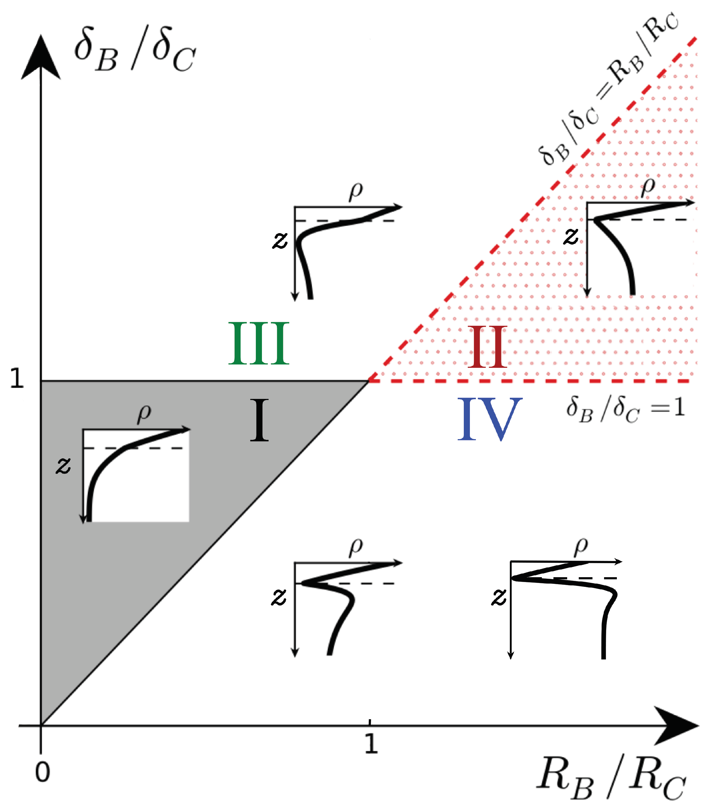
We first recall the types of density profiles that develop when the density of the host fluid increases upon dissolution () [17]. These profiles are classified in a parameter space spanned by the ratios (, ), as shown in Figure 1. In Zone I of the parameter space (), the density profile is monotonic and always decreases along z like its non-reactive counterpart. In Zone II (), a minimum of density is present at the reaction front where A and B meet by diffusion and react.
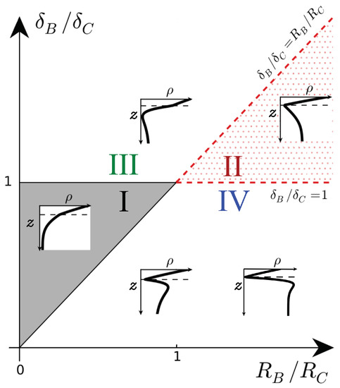
Figure 1.
Schematic density profiles in the (, ) parameter plane for and . The dashed line shows the location of the reaction front. I: monotonic decreasing, II: minimum at the reaction front, III: minimum below the reaction front, IV: minimum at the reaction front followed by a maximum. Adapted from [17].
When all species diffuse at the same rate (), only those two scenarios are possible. The corresponding nonlinear convective dynamics have already been studied numerically previously [6,12,13]. In the first scenario (belonging to Zone I), the product C is denser than reactant B, and the density profiles are monotonic. The reactive nonlinear dynamics are similar to those in the non-reactive case: fingers of denser fluid sink into the less dense bulk fluid, but with a larger velocity and more intense fingering. The second scenario possible for equal diffusion coefficients belongs to Zone II with C being less dense than B and the density profiles featuring a minimum. In that case, the minimum slows down the development and the progression of the fingers in the host fluid because it corresponds to a stable zone where locally less dense fluid lies on top of denser fluid.
Even though differential effects might affect those conclusions, we do not analyze Zones I and II any further here to focus on Zones III and IV. Indeed, they have not been investigated yet because they do not include cases where all species diffuse at the same rate. In Zone III (), the density profiles have a minimum like in Zone II, but that minimum is located below rather than at the reaction front [17]. Compared to the equal diffusivity case, the slow diffusing product C is more present at the top of the host fluid where it is produced and less present below the reaction front as it diffuses more slowly. Hence, a local depletion develops where B has been consumed if C is sufficiently dense (). In Zone IV (), the density profiles have a minimum at the reaction front followed by a maximum below it. This maximum is caused by a local accumulation of reactant B below the reaction front if B does not diffuse fast enough and contributes to the density sufficiently (). A detailed analysis of the RD profiles is provided in [17].
3.2. Fingering Dynamics
Now that we have analyzed the different types of RD density profiles, i.e., the density profiles in the host fluid before convection sets in, we investigate the dynamics in the fully developed nonlinear regime for Zones III and IV when all species contribute similarly to density but diffuse at different rates. In all simulations, we choose and .
3.2.1. Zone III
We first illustrate the type of convective dynamics observed for Zone III of Figure 1 with the specific case , and , shown in Figure 2. We have checked that the same type of dynamics can be observed for other values of the parameters as long as we stay in Zone III.
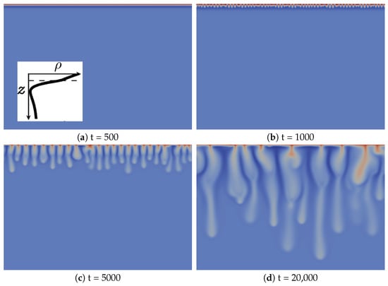
Figure 2.
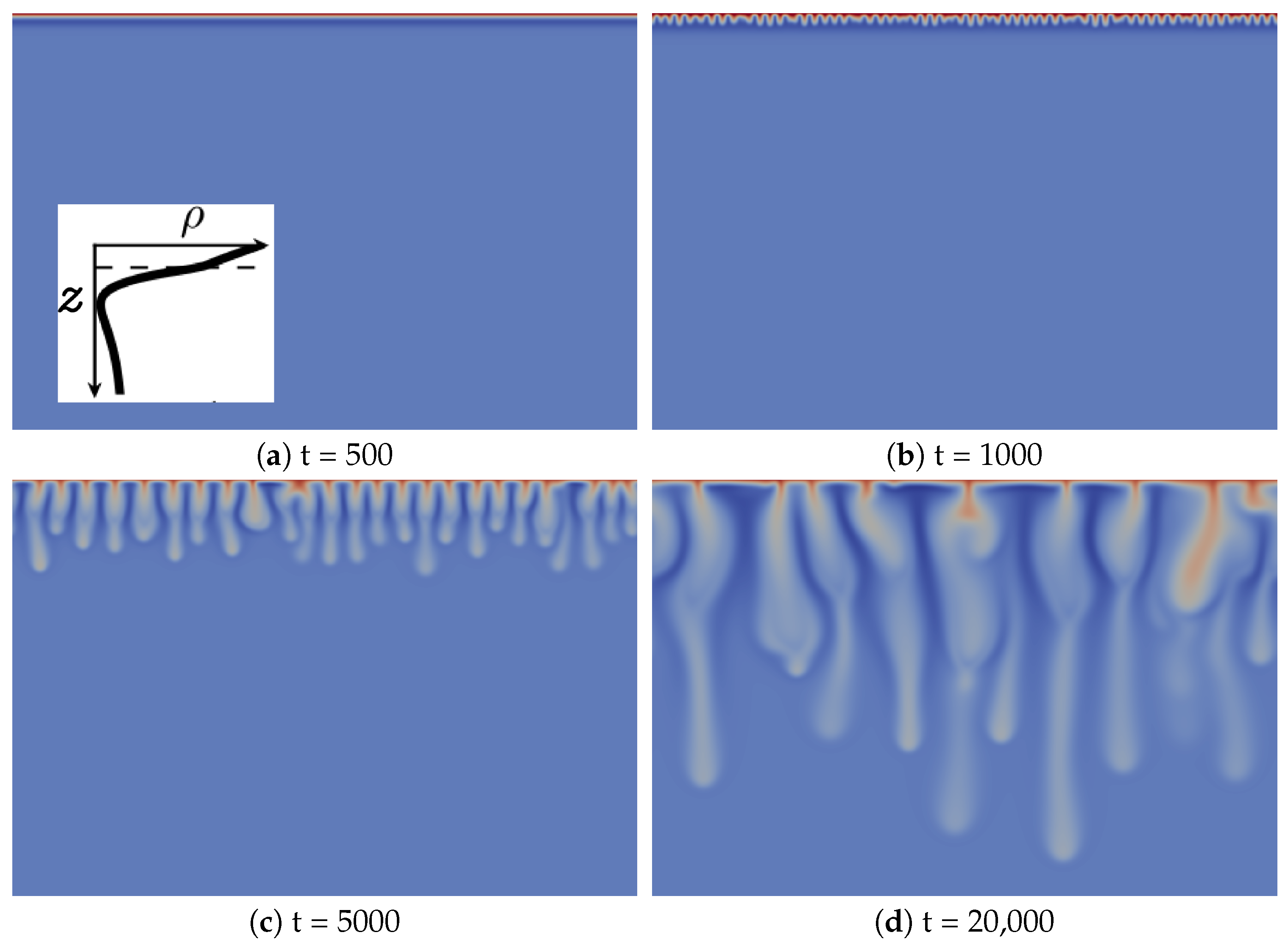
Density fields at different times (a–d) illustrating the fingering dynamics in Zone III (, and ). A typical reaction-diffusion density profile is enclosed in Figure 2a. The density scale varies between 0.75 (dark blue) and two (red).
The development of the reactive convective dissolution instability characterized by the onset of sinking convective fingers upon dissolution of A in the host layer is similar to that in the non-reactive case, as it can be characterized by the same regimes [13]. Initially, the system is stable with regard to convection (diffusive regime; Figure 2a). The density stratification is then characteristic of Zone III (see the typical RD density profile enclosed in Figure 2a): a denser fluid layer (red), rich in dissolving species A and/or product C, lies above a minimum of density (dark blue) on top of bulk fluid (light blue). At time 1000, fingers are visible, but do not interact significantly with each other (linear growth regime; Figure 2b). After the merging regime, the number of fingers has significantly decreased (Figure 2c). In the reinitiation regime, protoplumes are regularly generated from the boundary layer and merge with older existing fingers (Figure 2d). In addition, like in the non-reactive case, there is only one single convection zone visible, where denser fingers sink from the top into the less dense bulk solution [13]. This is to be contrasted with the fingering dynamics in Zone IV (see the following subsection).
The main difference between the fingering dynamics in Zone III and the non-reactive counterpart is the specific morphology of the fingers, which has not been observed when species diffuse at the same rate [13]. In the linear growth regime, finger tips are located above the minimum of density (dark blue in Figure 2b). By contrast, at later times corresponding to the nonlinear regime (Figure 2c,d), finger tips are located below that minimum, which means that the fingers move downwards faster than the minimum of density. Fingers are then larger above the minimum of density and narrower below.
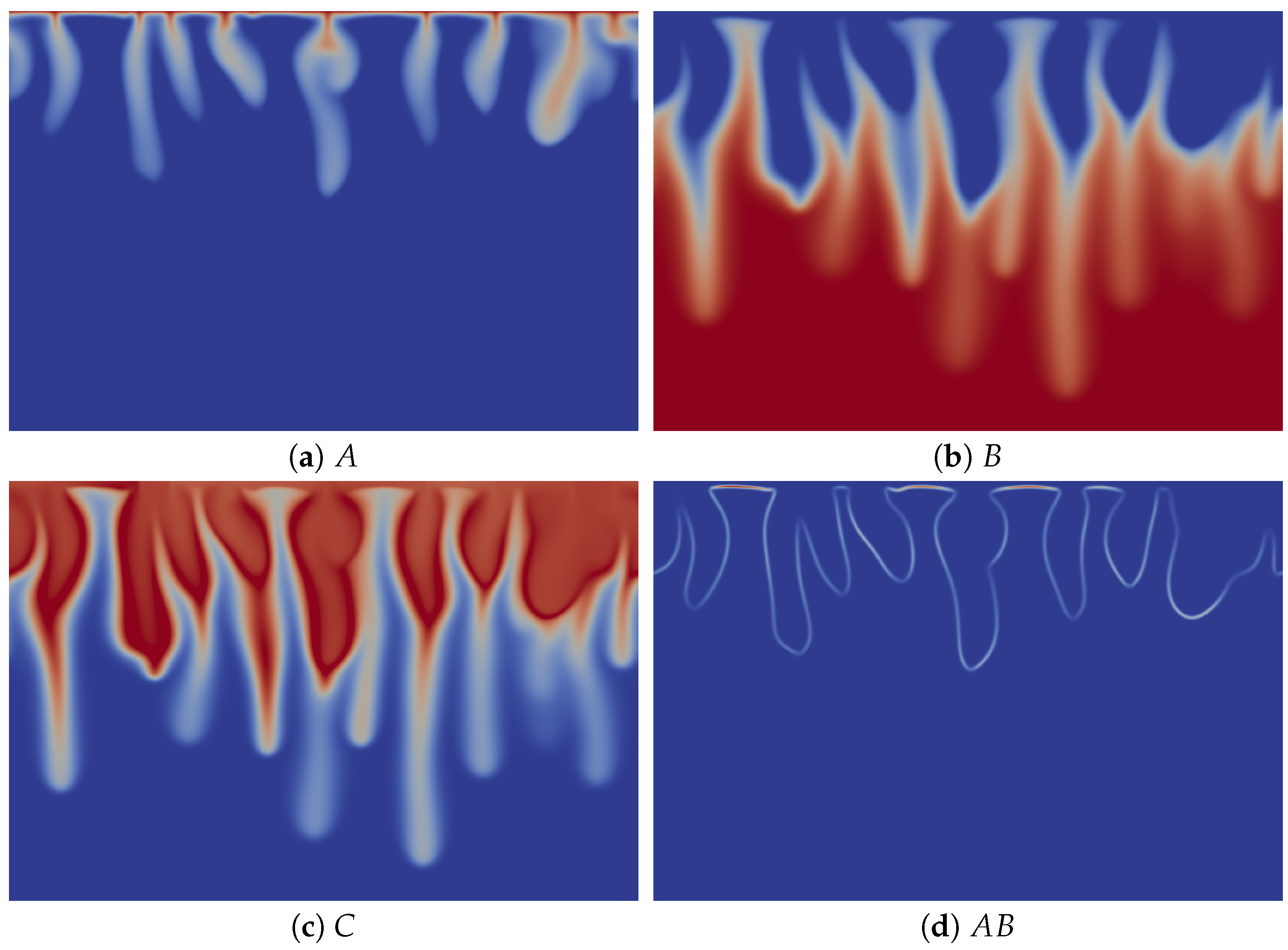
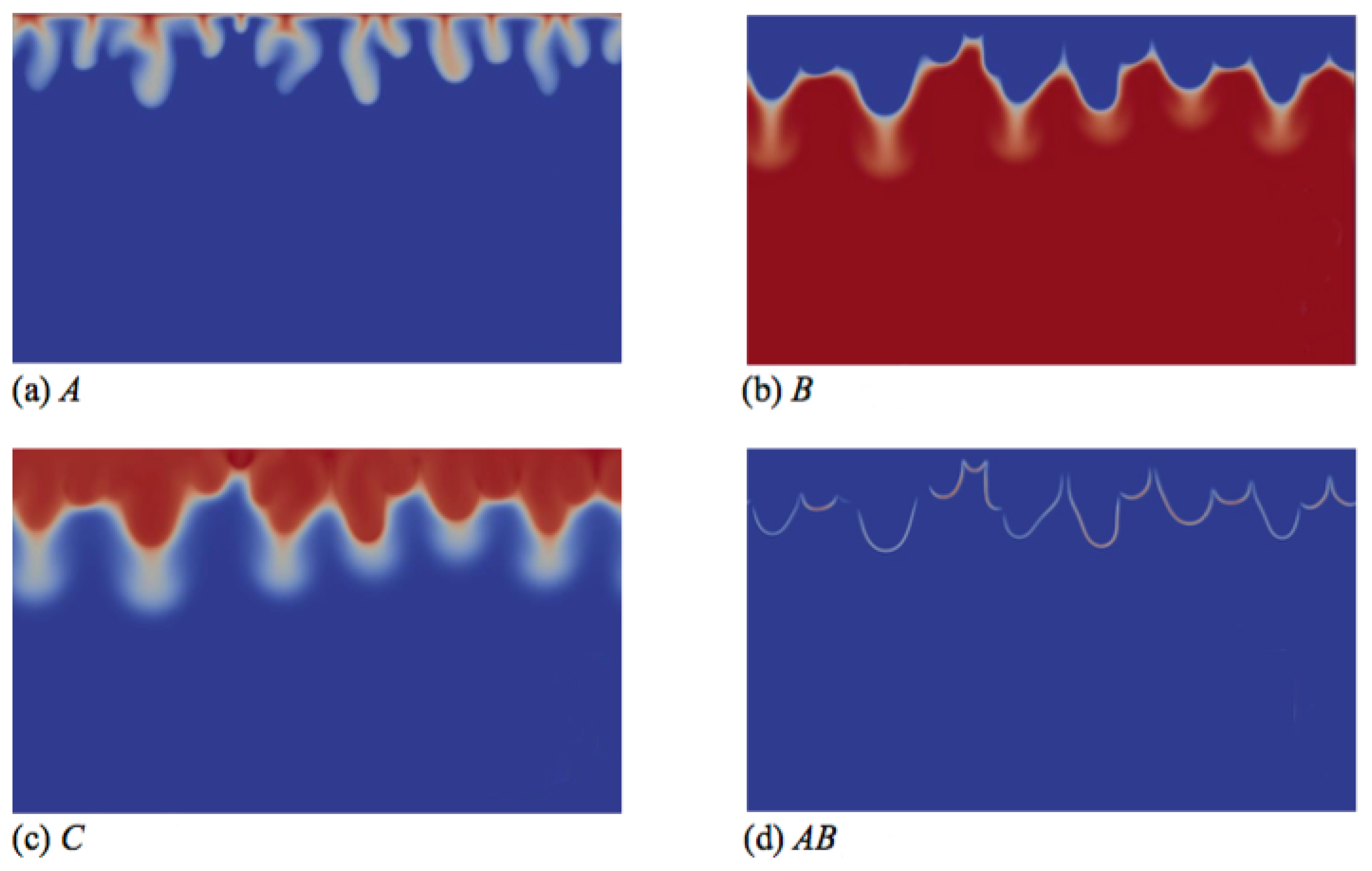
To understand the origin of this specific finger morphology, we compare the concentration fields illustrated in Figure 3a–c at time t = 20,000 to the corresponding density field shown in Figure 2d. The upper part of the fingers in the density map, above the minimum of density, mainly corresponds to the fingers of solute A, which have the same width (Figure 3a), while the tops of the fingers of B and C are wider (Figure 3b,c). By contrast, the lower thinner part of the density fingers, below the minimum of density, is only due to the fingers of B and C, which also have a second thinner part below the location of the minimum of density (Figure 3b,c). We explain this characteristic morphology of the fingers by the role of the stabilizing zone of the minimum of density where less dense fluid lies on top of a denser one in the gravity field. As a consequence, this barrier hinders the downward movement of the fingers, but does not stop them, as its amplitude is not large enough to counteract the unstable effect of the larger concentration of C on the density gradient. The fact that the fingers are narrower below the minimum of density expresses this hindering. We also note that the product C is more concentrated close to the contours of the upper part of the fingers (Figure 3c), where the reaction rate is the highest (Figure 3d).
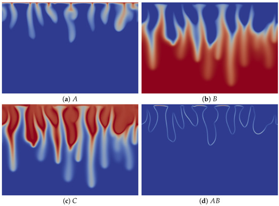
Figure 3.
Concentrations fields of (a) A; (b) B; (c) C; and (d) reaction rate AB field corresponding to the density field shown in Figure 2d (t = 20,000). Concentrations scale between zero (dark blue) and one (red), while the reaction rate scales between zero (dark blue) and 0.002 (red).
3.2.2. Zone IV
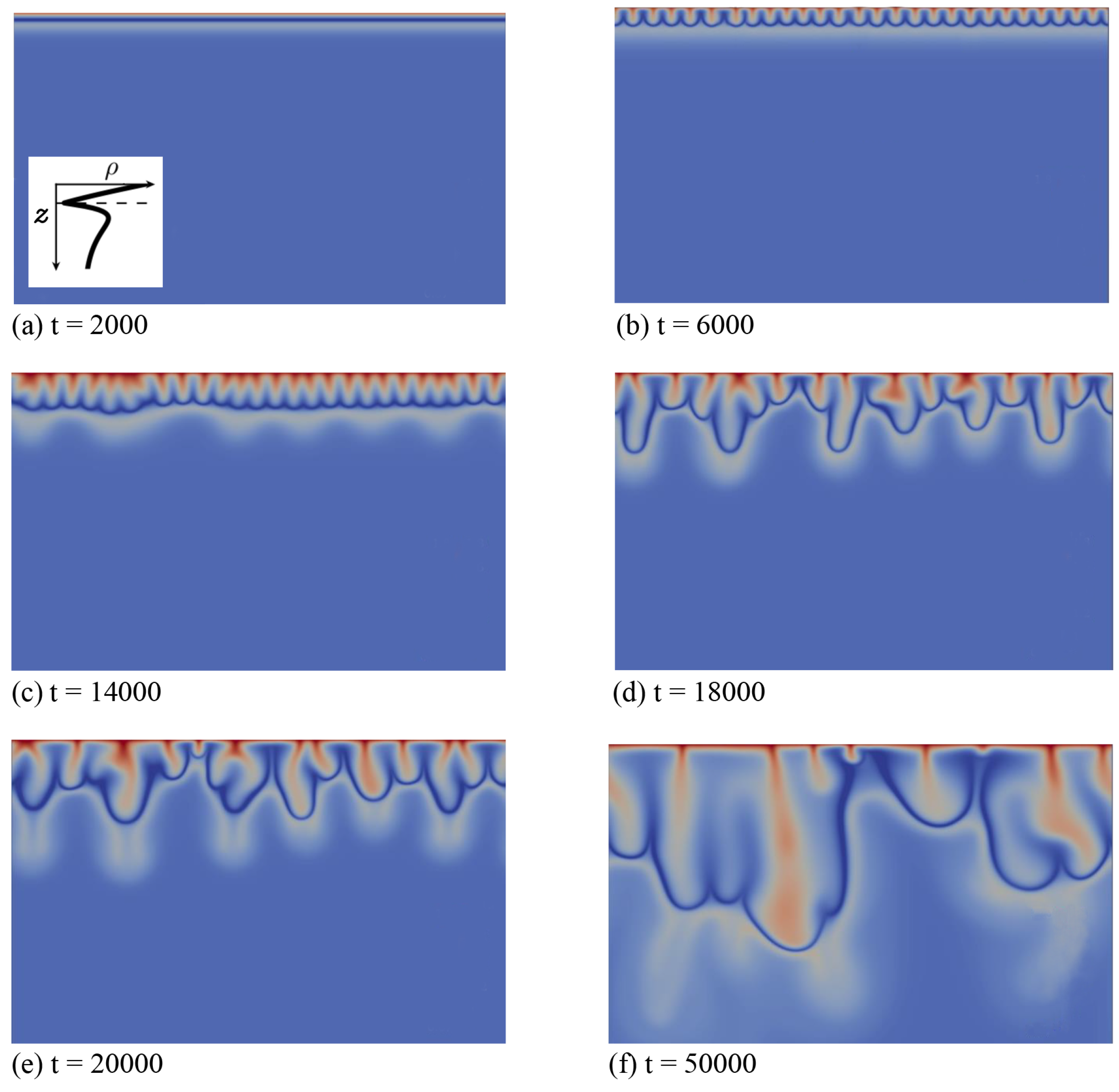
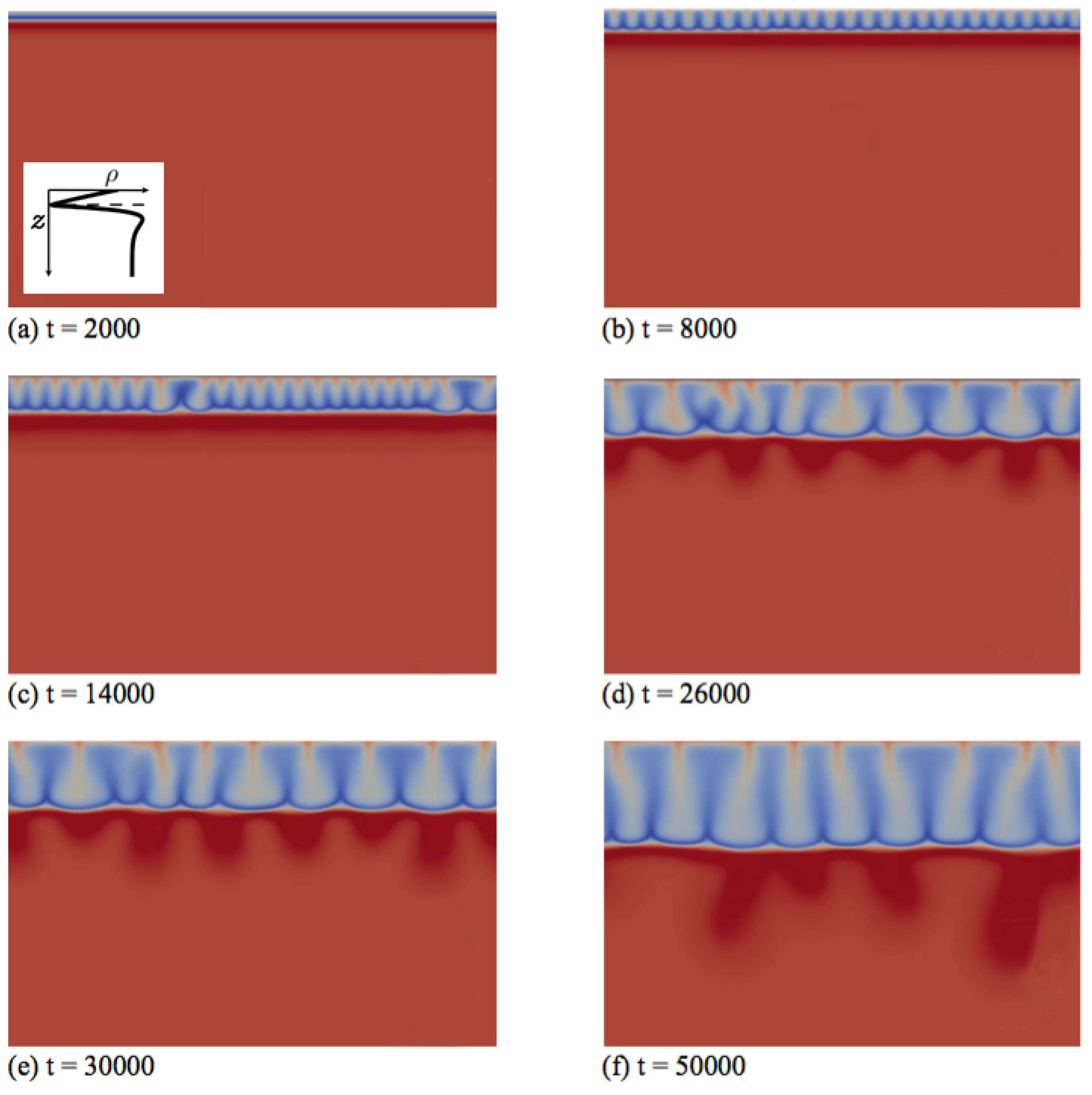
Secondly, we discuss the type of fingering dynamics observed in Zone IV, which we illustrate first for the left profile of that zone in Figure 1. This profile features a minimum followed by a maximum when z increases downwards and its density at the interface is larger than the bulk density (specific case , and ). In the initial diffusive regime shown in Figure 4a, the density stratification characteristic of Zone IV is clearly visible: a denser fluid layer rich in dissolving species A and product C (red) overlies the minimum of density at the reaction front (dark blue), located above a maximum of density (very light blue) on top of the bulk fluid (light blue). After some time, fingers appear and grow linearly above the minimum in density without interacting together (Figure 4b).
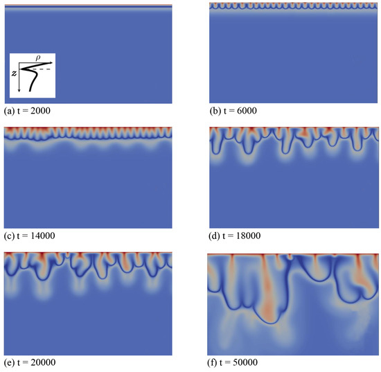
Figure 4.
Density fields at different times (a–f) illustrating the fingering dynamics in Zone IV for the density profile enclosed in the first panel (, and ). The density scale varies between 0.87 (dark blue) and 1.8 (red).
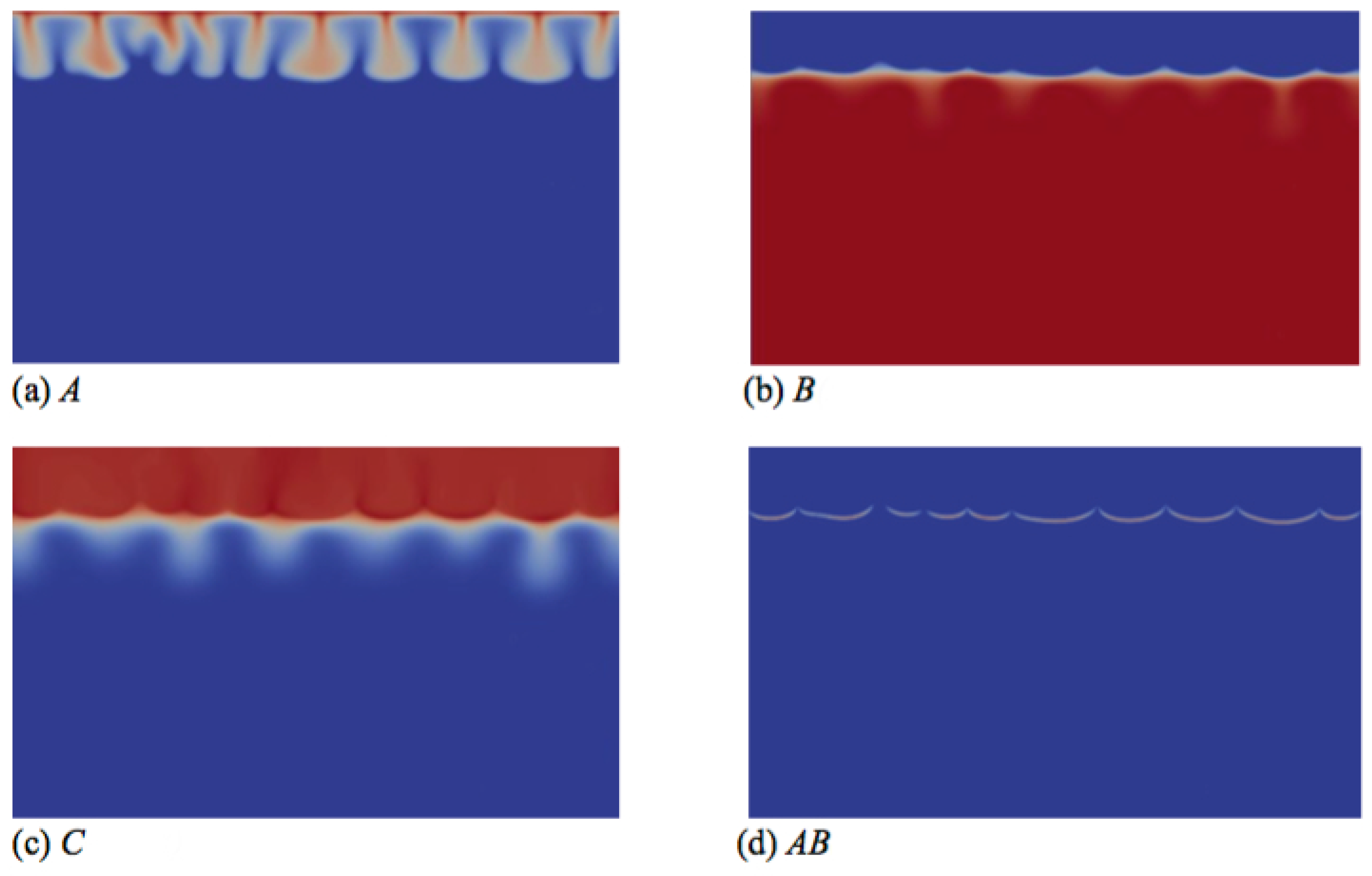
In contrast to Zone III, where only one convection zone is possible, two convection zones develop in Zone IV, as illustrated, e.g., in Figure 4c–f. The first convection zone corresponds to the density stratification extending from the interface, where A dissolves and increases the density of the solution, down to the minimum of density at the reaction front, where the reaction rate is the largest (Figure 5d). The fingering pattern appears in that zone first (Figure 4b) and corresponds mainly to the fingering pattern of the dissolving species A (Figure 4d and Figure 5a), although B and C also contribute, but with wider fingers (Figure 5b,c). Classical merging and, later, the appearance of new protoplumes (new fingers) are observed in this upper zone and are mainly due to the further dissolution of A. At larger times, an additional fingering pattern with a larger wavelength becomes visible below that first upper convective zone, under the minimum in density (Figure 4c). This secondary fingered convection zone is induced by the unstable density stratification below the reaction front, more precisely between the maximum of density rich in B and C and the bulk fluid containing only reactant B, as seen from the concentration maps of Figure 5b,c. Note the specific division of the lower fingers into two antennas (Figure 4e). This is characteristic of a mixed-mode regime developing when a differential layer convection (DLC) mode influences a Rayleigh–Taylor instability as characterized previously both experimentally and numerically in non-reactive miscible systems [24]. This typically occurs when a denser zone of a fast-diffusing solute overlies a less dense zone of a slow-diffusing solute. In our specific case, the situation is analogous, as is here smaller than one. We have then a local stratification around the maximum of density of a denser zone rich in fast-diffusing C above a less dense zone of the slowly-diffusing B, prone to exhibit the characteristic antenna-shaped fingers of the mixed mode.
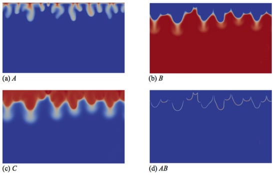
Figure 5.
Concentrations fields of (a) A; (b) B; (c) C; and (d) reaction rate AB field corresponding to the density field shown in Figure 4e (t = 20,000). Concentrations scale between zero (dark blue) and one (red), while the reaction rate scales between zero (dark blue) and 0.003 (red).
The qualitative features of convective dissolution are hence strongly modified by differential diffusivity effects: two different zones of convection and antenna-shaped fingers can be obtained instead of only one convection zone with regular fingers in the non-reactive or iso-diffusivity reactive cases. This study confirms the fact that reactions are able to profoundly affect partially miscible convection by inducing successive different buoyancy-driven instabilities and differential diffusion effects, as already demonstrated in miscible reactive systems [25].
In Figure 4, we see that the two convection zones are separated by a deep blue boundary corresponding to the location of the minimum of density (Figure 4) and of the reaction front (Figure 5). The upper fingers are bounded by this curve, contrary to the case of Zone III (Figure 2), where fingers move downwards across this minimum density zone. This is related to the relative importance of the stabilizing barrier below the minimum compared to the destabilizing upper part between the interface and the minimum. In Zone III, the stabilizing barrier is too weak to refrain from the downward progression of fingers across the minimum (Figure 2). In Zone IV, the additional presence of the maximum increases the amplitude of the stabilizing barrier, which contains the upper fingers above the minimum in density (Figure 4). However, in the case studied in Figure 4, the density at the interface is still larger than the bulk density, and the overall Rayleigh–Taylor type of instability wins in deforming the dark blue zone of the minimum in density. The amplitude of this deformation decreases when the bulk density increases, similarly to what is observed in the miscible mixed mode cases [24]. To evidence this, Figure 6 and Figure 7 show the dynamics for the right profile in Zone IV of Figure 1 where the bulk density is larger than the density at the interface. This is obtained here for the same values of parameters as in Figure 4, but with a larger value of . The stabilizing barrier effect is stronger and maintains the reactive interface between the two different convective zones flat in the course of time.
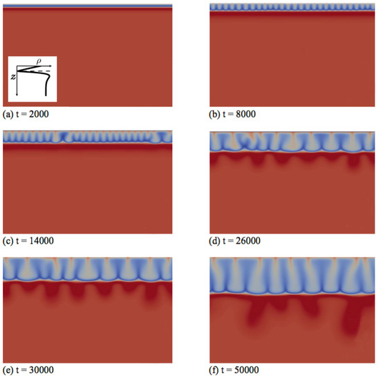
Figure 6.
Density fields at different times (a–f) illustrating the fingering dynamics in Zone IV for the density profile enclosed in the first panel (, and ). The density scale varies between 0.84 (dark blue) and 2.2 (red).
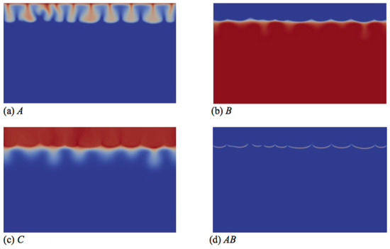
Figure 7.
Concentrations fields of (a) A; (b) B; (c) C; and (d) reaction rate AB field corresponding to the density field shown in Figure 6d (t = 26000). Concentrations scale between zero (dark blue) and one (red), while the reaction rate scales between zero (dark blue) and 0.003 (red).
3.3. Quantitative Effects
To appreciate the quantitative effect of differential diffusion on convective dissolution, we now consider a case where all species contribute equally to the density profile, i.e. and . We show that, if the reaction produces in situ a product C of different diffusivity, it can quantitatively change the rate of progression of fingers, the reaction rate, the dissolution flux and the amount of A stored. To do so, we also fix so that the reference reactant concentration profiles remain unchanged [17]. We vary so that the ratio varies from 0.5 to 2.
To assess the effect of differential diffusion quantitatively on the propagation of fingers in the host solution, we compute the mixing length , defined as the most advanced position along the vertical axis z where the sum of concentrations becomes smaller than 0.01 [13]. This allows us to analyze the temporal evolution of the mixing zone, i.e., the zone where A is dissolved, either unreacted or reacted (Product C).
By replacing in the RD asymptotic concentration profiles [17], we find that this mixing length evolves in the RD regime as:
where is the position of the reaction front, , in self-similar coordinates, which varies with the concentration ratio and both diffusivity ratios and .
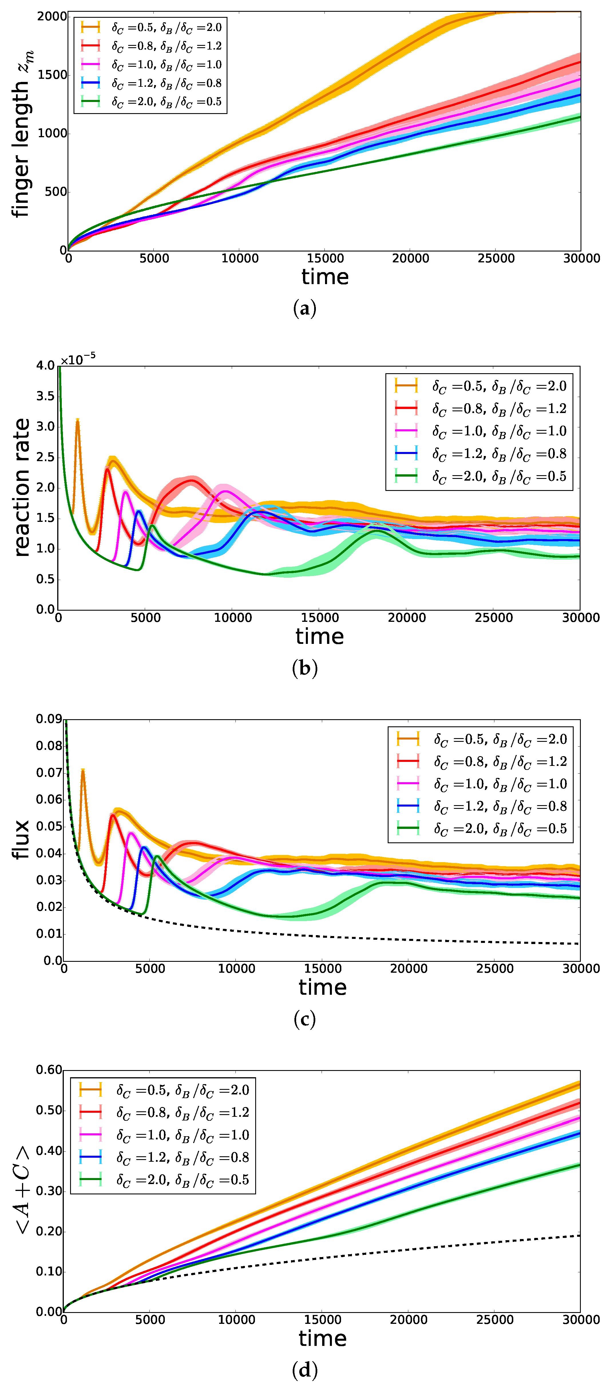
On the basis of Equation (7), we conclude that in the RD regime, the mixing length increases faster when the product C diffuses faster (i.e., increases). This is indeed observed at early times in Figure 8a. At later times, the mixing length starts to deviate from the diffusive regime when convection starts. The onset time of convection is seen to decrease when decreases (i.e., increases). This is related to the fact that, if C diffuses more slowly, it accumulates in the upper part of the system and increases the density just below the interface [17]. As a consequence, the reaction rate (Figure 8b) and the incoming flux of A (Figure 8c), computed as defined in [13], increase much faster and reach larger asymptotic values. As a result, the total amount of A present either as dissolved A or as reacted C increases when decreases, as can be seen in Figure 8d, featuring the volume-averaged quantity . When all species contribute equally to the density profile, we thus conclude that increasing has a destabilizing effect on convective dissolution.
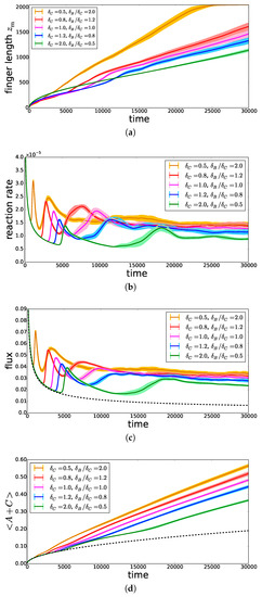
Figure 8.
Temporal evolution, for , , and different , of (a) the mixing length , (b) the average reaction rate , (c) the incoming flux of A and (d) the volume-averaged quantity , representing the total amount of A stored in the host solution. The lighter area around each curve represents the 95% confidence interval. The dashed black curves represent the solutions in the non-reactive corresponding case.
4. Conclusions
We have theoretically analyzed the influence of differential diffusion on the properties of nonlinear dynamics in reactive convective dissolution when a solute A dissolves into a host phase containing a solute B and an A + B → C reaction takes place. While only one type of density profile can develop in the non-reactive case if A increases the density of the host fluid (), two types of profiles can occur when all species diffuse at the same rate in the reactive case: a monotonic one similar to the non-reactive one and a non-monotonic profile with a minimum located at the reaction front provided C is less dense than B. Differential diffusion gives rise to two additional profiles: a non-monotonic profile with a minimum below the reaction front for and a non-monotonic profile with a minimum followed by a maximum when C diffuses faster than B ().
We have studied numerically the nonlinear dynamics of convective dissolution in the specific cases of these two additional density profiles when . For , the minimum located below the reaction front induces fingers that are wider above the minimum and thinner below it. Fingering develops faster than when C diffuses at the same rate as B, because the accumulation of C in the upper part of the system increases the unstable part of the density profile. When is increased, convection starts earlier and is more intense, which enhances transport and mixing in the host solution and leads to a larger reaction rate, dissolution flux and amount of stored A.
On the contrary, when the product C diffuses faster than the reactant B, i.e., , the density profile has a minimum at the reaction front followed by a maximum below it, which leads to a different type of convective dynamics. The finger progression is slowed down by the minimum of density while a secondary buoyancy-driven convection develops in the lower part of the solution. Two different convective dynamics are thus observed separated by the location of the minimum in density. When the relative intensity of the stabilizing barrier between the two extrema increases, the deformation in space of this minimum curve decreases. In addition, a diffusive layer convection instability can induce a deformation of the fingers of the lowest convective zone below the minimum into an antenna-shaped form. The faster diffusion of C also induces a later onset of convection, less intense mixing and smaller dissolution flux and reaction rate. As a consequence, the total amount of A stored in the form of A and C also increases more slowly.
This study has highlighted the major role that differential diffusivity effects can play in the development of reactive convective dissolution. Understanding those differential diffusivity effects is of tantamount importance for, among others, the realistic quantitative modeling of convective dissolution in CO sequestration techniques, where it is very likely that solutes in the host phases have different diffusion coefficients. A large part of the parameter space remains, however, unexplored. Future work could vary more extensively the values of Rayleigh numbers and diffusivity ratios to analyze the influence of the relative amplitudes of the density at the interface, in the minimum and maximum, as well as in the bulk on the properties of fingers.
Author Contributions
L.R. and A.D. conceived and supervised the research; V.L. and B.K. developed and validated the numerical code; V.L. and H.S. performed the simulations; All authors analysed the data; V.L. wrote the original draft; B.K., L.R. and A.D. reviewed and finalised the manuscript.
Funding
This research was funded by the PRODEX, ARC CONVINCE, ARC PIONEER, MIS-FNRS PYRAMID and PDR-FNRS CONTROL projects.
Acknowledgments
We thank V. Moureau and G. Lartigue for their training and support concerning the YALES2 code.
Conflicts of Interest
The authors declare no conflict of interest.
References
- Huppert, H.E.; Neufeld, J.A. The fluid mechanics of carbon dioxide sequestration. Annu. Rev. Fluid Mech. 2014, 46, 255–272. [Google Scholar] [CrossRef]
- Emami-Meybodi, H.; Hassanzadeh, H.; Green, C.P.; Ennis-King, J. Convective dissolution of CO2 in saline aquifers: Progress in modeling and experiments. Int. J. Greenh. Gas Control 2015, 40, 238–266. [Google Scholar] [CrossRef]
- Ghesmat, K.; Hassanzadeh, H.; Abedi, J. The impact of geochemistry on convective mixing in a gravitationally unstable diffusive boundary layer in porous media: CO2 storage in saline aquifers. J. Fluid Mech. 2011, 673, 480–512. [Google Scholar] [CrossRef]
- Cardoso, S.S.; Andres, J.T. Geochemistry of silicate-rich rocks can curtail spreading of carbon dioxide in subsurface aquifers. Nat. Commun. 2014, 5, 5743. [Google Scholar] [CrossRef] [PubMed]
- Ward, T.J.; Cliffe, K.A.; Jensen, O.E.; Power, H. Dissolution-driven porous-medium convection in the presence of chemical reaction. J. Fluid Mech. 2014, 747, 316–349. [Google Scholar] [CrossRef]
- Budroni, M.A.; Riolfo, L.A.; Lemaigre, L.; Rossi, F.; Rustici, M.; De Wit, A. Chemical control of hydrodynamic instabilities in partially miscible two-layer systems. J. Phys. Chem. Lett. 2014, 5, 875–881. [Google Scholar] [CrossRef] [PubMed]
- Loodts, V.; Thomas, C.; Rongy, L.; De Wit, A. Control of convective dissolution by chemical reactions: General classification and application to CO2 dissolution in reactive aqueous solutions. Phys. Rev. Lett. 2014, 113, 114501. [Google Scholar] [CrossRef] [PubMed]
- Loodts, V.; Rongy, L.; De Wit, A. Chemical control of dissolution-driven convection in partially miscible systems: Theoretical classification. Phys. Chem. Chem. Phys. 2015, 17, 29814–29823. [Google Scholar] [CrossRef] [PubMed]
- Cherezov, I.; Cardoso, S.S. Acceleration of convective dissolution by chemical reaction in a Hele–Shaw cell. Phys. Chem. Chem. Phys. 2016, 18, 23727–23736. [Google Scholar] [CrossRef] [PubMed]
- Kim, M.C.; Wylock, C. Linear and nonlinear analyses of the effect of chemical reaction on the onset of buoyancy-driven instability in a CO2 absorption process in a porous medium or Hele-Shaw cell. Can. J. Chem. Eng. 2017, 95, 589–604. [Google Scholar] [CrossRef]
- Ghoshal, P.; Kim, M.C.; Cardoso, S.S. Reactive convective dissolution in a porous medium: The storage of carbon dioxide in saline aquifers. Phys. Chem. Chem. Phys. 2017, 19, 644–655. [Google Scholar] [CrossRef] [PubMed]
- Budroni, M.A.; Thomas, C.; De Wit, A. Chemical control of dissolution-driven convection in partially miscible systems: Nonlinear simulations and experiments. Phys. Chem. Chem. Phys. 2017, 19, 7936–7946. [Google Scholar] [CrossRef] [PubMed]
- Loodts, V.; Knaepen, B.; Rongy, L.; De Wit, A. Enhanced steady-state dissolution flux in reactive convective dissolution. Phys. Chem. Chem. Phys. 2017, 19, 18565–18579. [Google Scholar] [CrossRef] [PubMed]
- Gutkowicz-Krusin, D.; Ross, J. Rayleigh-Bénard instability in n-component reactive fluids. J. Chem. Phys. 1980, 72, 3588–3595. [Google Scholar] [CrossRef]
- Wylock, C.; Rednikov, A.; Haut, B.; Colinet, P. Nonmonotonic Rayleigh-Taylor instabilities driven by gas-liquid CO2 chemisorption. J. Phys. Chem. B 2014, 118, 11323–11329. [Google Scholar] [CrossRef] [PubMed]
- Thomas, C.; Loodts, V.; Rongy, L.; De Wit, A. Convective dissolution of CO2 in reactive alkaline solutions: Active role of spectator ions. Int. J. Greenh. Gas Control 2016, 53, 230–242. [Google Scholar] [CrossRef]
- Loodts, V.; Trevelyan, P.M.J.; Rongy, L.; De Wit, A. Density profiles around A + B → C reaction-diffusion fronts in partially miscible systems: A general classification. Phys. Rev. E 2016, 94, 043115. [Google Scholar] [CrossRef] [PubMed]
- Bestehorn, M.; Firoozabadi, A. Effect of fluctuations on the onset of density-driven convection in porous media. Phys. Fluids 2012, 24, 114102. [Google Scholar] [CrossRef]
- Tilton, N.; Daniel, D.; Riaz, A. The initial transient period of gravitationally unstable diffusive boundary layers developing in porous media. Phys. Fluids 2013, 25, 092107. [Google Scholar] [CrossRef]
- Moureau, V.; Domingo, P.; Vervisch, L. Design of a massively parallel CFD code for complex geometries. C. R. Mec. 2011, 339, 141–148. [Google Scholar] [CrossRef]
- Loodts, V. Influence of Chemical Reactions on Convective Dissolution: A Theoretical Study. Ph.D. Thesis, Université libre de Bruxelles, Brussels, Belgium, 2016. [Google Scholar]
- Kraushaar, M. Application of the Compressible and Low-Mach Number Approaches to Large-Eddy Simulation of Turbulent Flows in Aero-Engines. Ph.D. Thesis, Institut National Polytechnique de Toulouse (INPT), Toulouse, France, 2011. [Google Scholar]
- Falgout, R.D.; Jones, J.E.; Yang, U.M. Numerical Solution of Partial Differential Equations on Parallel Computers, Volume 51 of Lecture Notes in Computational Science and Engineering; Bruaset, A.M., Tveito, A., Eds.; Springer: Berlin, Germany, 2006. [Google Scholar]
- Carballido-Landeira, J.; Trevelyan, P.M.; Almarcha, C.; De Wit, A. Mixed-mode instability of a miscible interface due to coupling between Rayleigh-Taylor and double-diffusive convective modes. Phys. Fluids 2013, 25, 024107. [Google Scholar] [CrossRef]
- Lemaigre, L.; Budroni, M.A.; Riolfo, L.A.; Grosfils, P.; De Wit, A. Asymmetric Rayleigh-Taylor and double-diffusive fingers in reactive systems. Phys. Fluids 2013, 25, 014103. [Google Scholar] [CrossRef]
© 2018 by the authors. Licensee MDPI, Basel, Switzerland. This article is an open access article distributed under the terms and conditions of the Creative Commons Attribution (CC BY) license (http://creativecommons.org/licenses/by/4.0/).

