Abstract
Multi-scale fractal grids can be considered to mimic the fractal characteristic of objects of complex appearance in nature, such as branching pulmonary network and corals in biology, river network, trees, and cumulus clouds in geophysics, and the large-scale structure of the universe in astronomy. Understanding the role that multiple length scales have in momentum and energy transport is essential for effective utilization of fractal grids in a wide variety of engineering applications. Fractal square grids, consisted of the basic square pattern, have been used for enhancing fluid mixing as a passive flow control strategy. While previous studies have solidified the dominant effect of the largest scale, effects of the smaller scales and the interaction of the range of scales on the generated turbulent flow remain unclear. This research is to determine the relationship between the fractal scales (varying with the fractal iteration N), the turbulence statistics of the flow and the pressure drop across the fractal square grids using well-controlled water-tunnel experiments. Instantaneous and ensemble-averaged velocity fields are obtained by a planar Particle Image Velocimetry (PIV) method for a set of fractal square grids (N = 1, 2 and 4) at Reynolds number of 3400. The static pressure drop across the fractal square grid is measured by a differential pressure transducer. Flow fields indicate that the multiple jets, wakes and the shear layers produced by the multiple scales of bars are the fundamental flow physics that promote momentum transport in the fractal grid generated turbulence. The wake interaction length scale model is modified to incorporate the effects of smaller scales and thereof interaction, by the effective mesh size and an empirical coefficient . Effectiveness of a fractal square grid is assessed using the gained turbulence intensity and Reynolds shear stress level at the cost of pressure loss, which varies with the distance downstream. In light of the promising capability of the fractal grids to enhance momentum and energy transport, this work can potentially benefit a wide variety of applications where energy efficient mixing or convective heat transfer is a key process.
1. Introduction
As an object composed of a hierarchy of length scales (or multi-scale) is partially or fully immersed in a fluid flow, various scales of turbulent flow motions are induced in response to the object’s different scales. For instance, when wind blows over trees that display a range of length scales in their branches, the air flow around the trees has complex multi-scale features which are governed by highly nonlinear dynamics. Understanding the flow physics and modeling the momentum and energy transport between the trees and the wind have been areas of sustained interest [1,2,3,4,5]. One particular type of such multi-scale objects is a fractal, which is consisted of self-similar patterns superimposed at different length scales [6]. The multi-scale fractal grids, commonly classified as I-grid, cross-grid and square grid, can be considered to mimic the fractal characteristic of objects in nature, such as branching pulmonary network and corals in biology, river network, trees, and cumulus clouds in geophysics, and the large-scale structure of the universe in astronomy.
Over the decades multi-scale objects and elements, the real characters of the physical world, have been simplified to have either a single primary or a limited number of length scales. This simplification is widely accepted in understanding and modeling the interaction between flows and immersed multi-scale objects. For example, trees have been modeled by the length scales of large trunks and an overall leaf-area density distribution [7]. Smaller branches and their effects in transport processes are not considered. However, flow properties are affected by multi-scale objects reveal considerable variability over a broad range of spatial and temporal scales; i.e., they are clearly of multi-scale nature [8,9]. Understanding the role that multiple length scales have in momentum and energy transport is essential for complex fluid dynamics of a wide variety of engineering applications.
Fractal grids have been adopted as a passive flow control strategy to enhance fluid mixing and convective heat transfer, which remains a topic of great interest due to the high demand for effective and efficient flow-control devices. The fractility of such grids generates vortices of different sizes that interact at different locations downstream of the grid. Furthermore, the set of geometric parameters of the fractal grid can be purposely tuned to alter the location and magnitude of the peak turbulence intensity [10], thus making the fractal grids attractive for highly controlled mixing and heat transfer. Fractal grids have been recently used to renovate the design of wind fences, heat exchanger fins, and low-swirl combustion chambers [11,12,13].
Extensive experiments and numerical simulations have been carried out over the last decade to understand the fractal grid-generated turbulence and how the geometric parameters affect the flow. This is of paramount importance as the location of the maximum in the turbulence intensity distribution can be tuned as a function of the fractal grid geometric parameters. Unique turbulent flow of different scales are induced by fractal grids, compared to that of conventional or uniform grids. These turbulent scales interact with each other and exhibit remarkably different properties compared with previously documented turbulent flows, and they have been considered to form a “new class of turbulence” [14,15]. Direct numerical simulations (DNS) have shown that fractal grids produce intermittent multi-scale wakes, with the smallest wakes interacting closest to the grid and the largest wakes interacting furthest from the grid [10,16]. Subsequently, beyond the immediate wake region of the grid, the fractal grid generates notably higher turbulence intensities along the centerline when compared to their counterparts—conventional grids with much higher blockage ratios (and therefore, higher pressure drops).
The sizes of these multiscale wakes and the location of wake interaction is determined by the geometric parameters of the fractal grid. An important scaling parameter, the wake interaction length scale = /, was introduced by Mazellier and Vassilicos (2010) [10], where () is the length (thickness) of the largest bar. It separates the near-grid region with high anisotropic turbulence and the far-region of approximately isotropic turbulence [17]. This parameter has been used to predict , the location of peak centerline turbulence intensity for fractal grids, single square grids, and conventional grids. The location of peak centerline turbulence intensity for the single square grid occurs closer to the grid than the fractal square grid, which can be explained by the difference in the wake interaction length scale between the two grids [18]. Gomes-Fernandes et al. (2012) [17] proposed a correction of this scaling law by taking into account the upstream turbulence level.
Previous researches also examined how the geometric parameters of fractal grids impact the magnitude of peak centerline turbulence intensity and subsequently heat transfer rate. The ratio / determines the magnitude of the peak centerline turbulence intensity, with ∝ /, where is the drag coefficient of the largest bars of the fractal grid [17,18]. The relationship ∝ / suggests that the additional fractal scales would have little to no impact on the magnitude of the peak turbulence intensity, as long as the dimensions of the largest bar remain constant (/). Wind-tunnel experiments on turbulent flows generated by a fractal grid, a single square grid, and a conventional grid, all having different / were reported by Melina et al. (2016, 2017) [18] . This study confirmed that a single square grid with larger / and lower blockage ratio can increase turbulence intensity and heat transfer compared to the other grids [19]. Furthermore, early research has shown that for fractal square grids with thickness ratios equal to or greater than 8.5, the largest square is considered to dominantly contribute to the turbulence intensity peak and its location and the thickness of the smallest squares are negligible [14,17].
The question naturally arises about the significance of additional scales in modifying the fractal grid-induced turbulence, with the largest scale being dominant. In the vast majority of the research to date, comparisons between a fractal square grid and single square grid have been conducted with grids of different values of /, based on the rational that the peak centerline turbulence intensity is proportional to /. There have only been very limited studies on fractal square grids with a constant /. For example, Cafiero et al. (2014, 2017) [20,21] studied the effects of grid geometric parameters on heat transfer enhancement of impinging jets. The heat transfer rate with a fractal grid of N = 3 was compared to that of a single square grid, which was created by simply removing the second and third iterations of the fractal grid. The fractal grid models employed in the study are of the thickness ratios less than 8.5 thus a clear difference associated with smaller scales is identified. The results of this study, suggesting the additional fractal scales have an noticeable impact on the heat transfer enhancement, are aligned with the earlier research. Another recent study compared the centerline streamwise turbulence intensity for fractal square grids (N = 1, 2, 3 and 4) having constant largest dimensions of and , focusing on the role of the fractal elements and what grid arrangement causes the elongated non-equilibrium region in the turbulent flow [22].
The pressure drop across a fractal grid is directly related to how much energy is consumed to compensate the loss. It would be desirable that a passive flow control device, such as a fractal grid, can significantly enhance turbulence level at a reasonable cost of energy consumption. There have been a few studies that report how the pressure drop across fractal grids increases with the blockage ratio, which is not different from conventional grids [18,19]. However, it will be more insightful to examine the effectiveness of a fractal grid based on the enhanced turbulence level (“gain”) and the associated pressure drop (“loss”) for engineering design of devices such as mixers or heat exchangers.
The present research aims to (1): understand how the multiple scales of a fractal square grid influence the flow structure, turbulence statistics and pressure drop; (2) revisit and modify the wake interaction length scale model to account for multiple scales’ effects. This is conducted by comparing the turbulence statistics and the pressure drop induced by each of a set of fractal square grids (with iterations N = 1, 2, and 4). Since the largest bar dimensions of and are held constant, systematically adding a smaller scale (by increasing the fractal iterations) allows to evaluate the effects of the different fractal scales and thereof interaction. Please note that the blockage ratio also increases as we add an additional scale, since they are coupled via Equation (6).
2. Experimental Facility and Measurement Methods
2.1. Fractal Grid Geometries
A set of fractal grids (FGs) are examined in this study: a single square grid FG1 (N = 1), a fractal square grid of four iterations FG4 (N = 4), and an intermediate configuration FG2 (N = 2), as shown in Figure 1. Specifically, FG4 is referred as a complete fractal. FG1 consisted of the largest element of FG4 only and FG2 consisted of the largest and the second-largest elements of FG4. Since FG1 and FG2 are essentially partial constructions of FG4, they have the same wake-interaction length scales based on the model by Mazellier et al. (2010) [10]. This design allows for the effects of additional fractal scales associated with successive fractal iteration to be evaluated. As a result, however, the blockage ratio is increased from FG1 to FG4 (Table 1.)

Figure 1.
Definition of scaling parameters of a fractal square grid. FG1, FG2 and FG4 from left to right.

Table 1.
Summary of the scaling parameters of fractal square grids (FG1, FG2 and FG4).
While having multiple length scales, fractal grids can be described by simple recursive mathematical expressions [14]. The fractal square grids are completely described by five scaling parameters: grid height (H), number of iterations (N), maximum bar length (), maximum bar thickness (), and minimum bar thickness (). Ratios of length scales and the fractal dimension are defined as follows:
() is the ratio of the length (thickness) at the fractal iteration j to that of the first generation. The fractal dimension is 2, which has been shown to produce the best turbulent homogeneity [14] . As discussed in Hurst, et al (2007) [14], the fractal grids can be compared to a conventional regular (or uniform) grid if using an effective mesh size
where P is the fractal grid perimeter and is the blockage ratio defined as,
For the fractal square grids employed here, the number of bars that the pattern requires S is 4, and the number of patterns at iteration j is 4. The scaling parameters of FG1, FG2 and FG4 are summarized in Table 1.
2.2. Water Tunnel and Inflow Conditions
Experiments were performed in a recirculating water tunnel with a test section of 0.3 m (W) × 0.3 m (H) × 2.0 m (L) at the Mechanical Engineering Department, Cleveland State University. Transparent side and bottom walls of the test section allow for full access for the optics and camera. The uniform inflow condition was characterized at the freestream velocity of 0.310 m/s, which corresponds to a Reynolds number of 3400 based on and the thickness of the largest bar . This inflow condition was chosen in order to create comparable Reynolds numbers to previous DNS studies [16,23].
The inflow is characterized by particle image velocimetry (PIV) measurements in the vertical center plane of the water tunnel. By ensemble-averaging 800 instantaneous velocity fields, the vertical profiles of mean streamwise velocity, streamwise turbulence intensity, vertical turbulence intensity, and Reynolds shear stress were obtained. The streamwise turbulence intensity is in the range of 2.0–2.5%, and the vertical turbulence intensity of 1.0–3.0%. This is slightly lower than previous PIV experiments with fractal square grids in a water tunnel reported by Gomes-Fernandes et al., (2012) [17], where the streamwise turbulence intensity was 2.8% and the spanwise turbulence intensity was 4.4%.
Each fractal grid was held to be secured to the walls of the water tunnel, by a rigid frame having an o-ring gasket around the edges. It is noted that this frame increases the overall blockage ratio and further accelerates the flow through the grid. Caution should be exercised when comparing to other work. However, the current experiment is to examine the flow generated by a set of fractal square grids mounted with the same frame, making it a fair comparison.
2.3. PIV Measurements
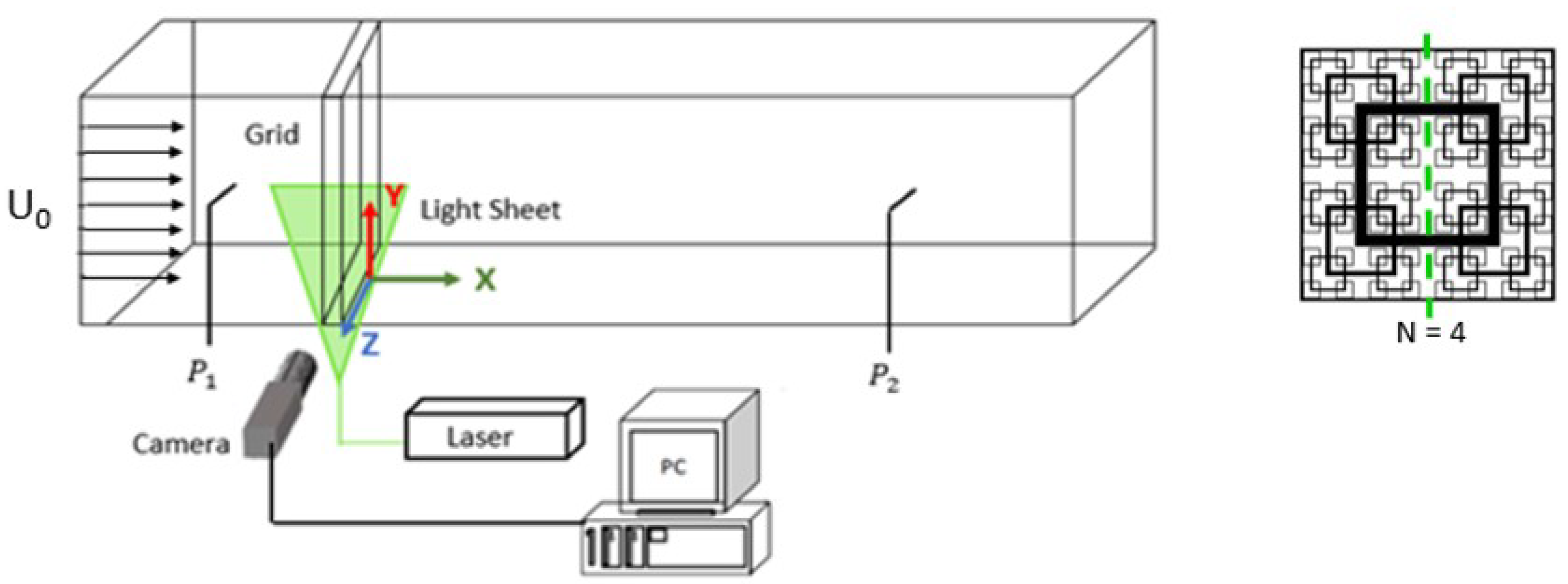
Measurements of the turbulent flow induced by a fractal sqaure grid are conducted using a two-dimensional two-component (2D2C) planar PIV system (Lavision Gmbh, Göttingen, Germany). As shown in Figure 2, the laser light sheet was positioned from the bottom of the water tunnel and directed along the centerline of the grid. Hollow glass spheres having a diameter of about 10 micrometers were used to seed the flow. A Pro-Imager SX 5MP CCD camera (2448 pixels by 2050 pixels) was employed to capture particle images with a field of view (FOV) of 205 mm by 172 mm at a rate of 7.28 frames per second (fps). Calibration was carried out by taking images of a scale which is carefully aligned with the light sheet. The scale images were used to convert the particle displacement from pixels to physical spatial coordinates.
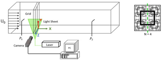
Figure 2.
Experimental setup and the location of PIV laser light sheet on the tested fractal grid.
A total of 1500 image pairs were recorded with a time step of 1200 microseconds between the pair of particle images. The instantaneous velocity fields were obtained using a window-based cross-correlation method (Davis 8.4, Lavision Gmbh, Göttingen, Germany). The interrogation window started at 64 × 64 pixels and reduced to 16 × 16 pixels with a 50% overlap. This yields a spatial resolution of 0.67 mm, sufficient to capture the related scales of the smallest bars. Erroneous vectors were replaced by interpolation of neighboring vectors using a Gaussian scheme. The processed instantaneous velocity fields were ensemble-averaged, resulting in the mean velocity fields and other turbulent quantities of the flow. Measurements were taken at seven different FOVs, with an overlap of 25 mm between two adjacent FOVs. With the ensemble-averaged results being stitched together, these seven FOVs are able to cover the region downstream of the grid up to 5.3 H and capture the entire turbulence production region, but not the turbulence decay region. The Cartesian coordinates are shown in Figure 2. Please note that the present 2D particle images resolved the instantaneous streamwise velocity u (in the x direction) and the vertical velocity v (in the y direction) in the single center plane of the generated turbulent flow.
2.4. Pressure Measurements
The static pressure drop across each fractal square grid was measured through two pressure taps on the side wall of the water tunnel, using a Validyne DP15 variable reluctance differential pressure transducer (an accuracy of +/− 0.5% full scale). The static pressure upstream of the fractal grid is nearly constant due to the uniformity of the incoming flow. As the pressure taps are fixed, shown in Figure 2, the fractal grid was translated to different positions to cover the similar range (downstream of the fractal grid) to that of the flow field measurements. The static pressure was sampled at a rate of 1000 Hz and recorded using a Validyne USB2250 data acquisition device (Northridge, CA, USA). The non-dimensional pressure drop is
where is the differential pressure drop measured across the fractal grid, is the water density, and is the pre-set freestream velocity.
3. Results and Discussion
3.1. Characteristic Flow Field: Jets and Wakes of Various Scales
A fundamental characteristic of these turbulence-generating grids is that they produce wakes immediately behind the bars and jets immediately behind the openings. More importantly, the multiple wakes are the strong signature of the different length scales of bars. This is distinctly different from the nearly uniform distribution of wakes and jets generated by a uniform grid, reported in previous studies, e.g., [13]. While the multi-scale jet-wake flow behavior was observed for complete fractal grids [10,16,24], the current results highlight the evolution of the jets and wakes with gradually including smaller scales by increasing N.
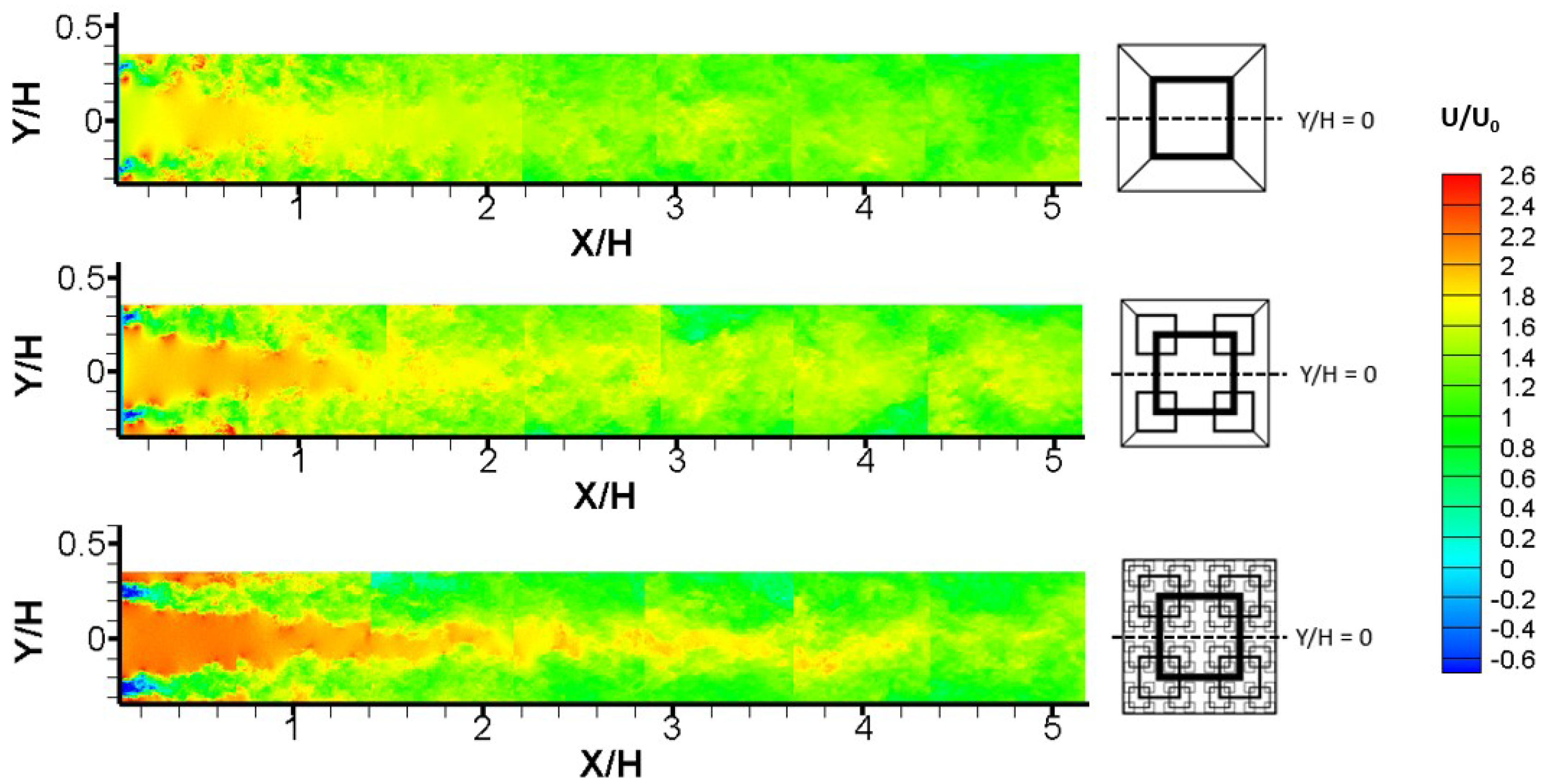
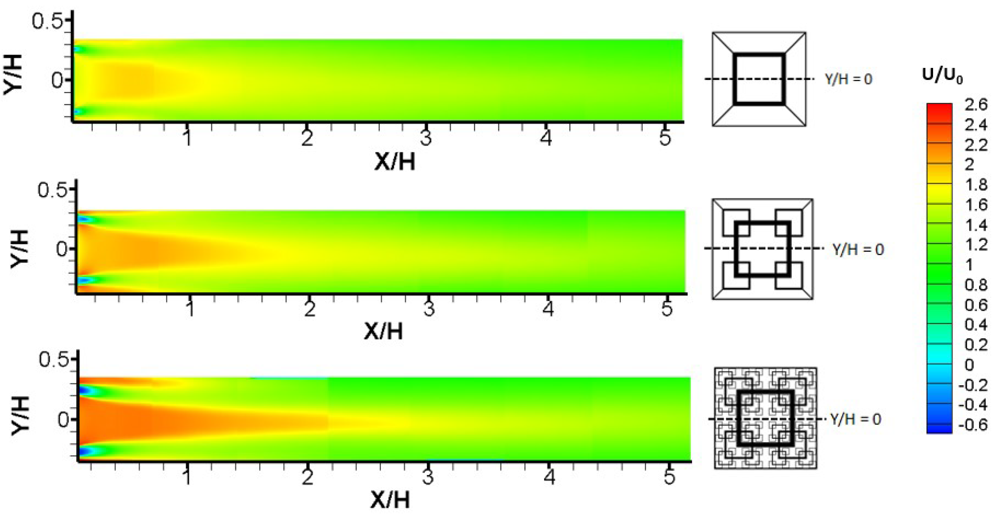
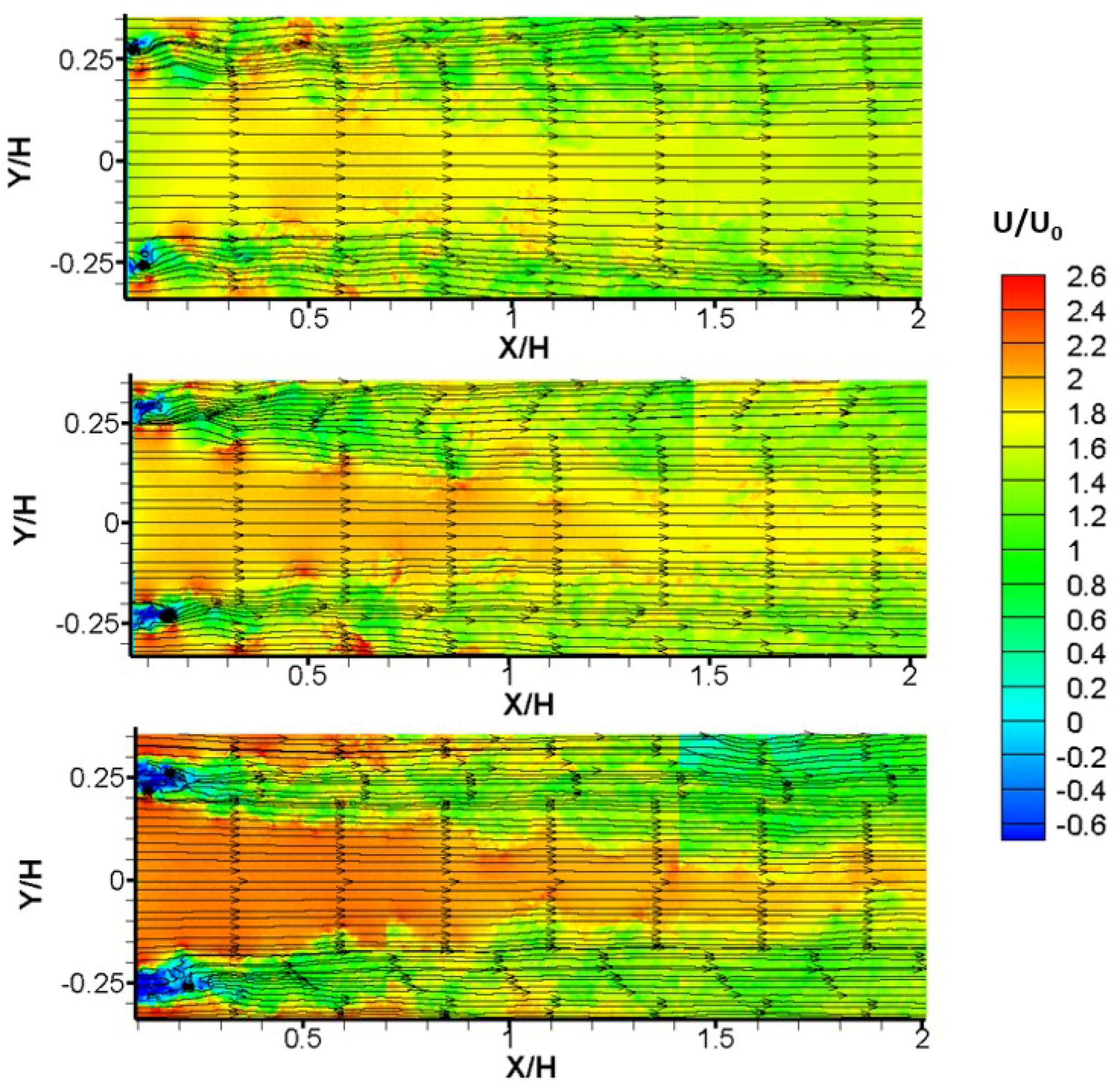
The instantaneous velocity fields in Figure 3 show that the division between the major jet and two adjacent wakes becomes more visible as additional fractal scales are added to the fractal grid (from FG1 to FG4). The near-wake is characterized by a reversed flow region. Immediately behind FG1, the reversed flow region is within = 0.1. It keeps increasing to = 0.17 for FG2 and reaches = 0.2 for FG4, owing to the cumulative reversed flow from each bar of different scales. In addition, as N increases the central jet becomes more intensive, evidenced by the highest (along the centerline) for FG4 and the lowest for FG1. The enhancement of jet velocity is about 25% comparing FG4 and FG1. The accelerated jet flow formed by the largest square is expected due to the gradual increase in blockage ratio with increasing N. Meanwhile, the jet becomes narrower and intensifies with two major wakes occupying larger areas before merging together. The ensemble-averaged velocity fields in Figure 4 confirm this flow characteristics with smoothing division of the central jet and two symmetric wake regions.
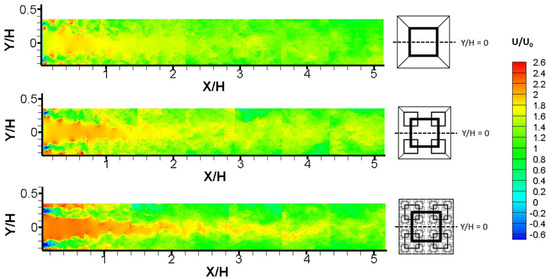
Figure 3.
Instantaneous streamwise velocity downstream of a fractal square grid at Re = 3400. FG1, FG2 and FG4 from top to bottom.
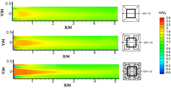
Figure 4.
Mean streamwise velocity downstream of a fractal square grid at Re = 3400. FG1, FG2 and FG4 from top to bottom.
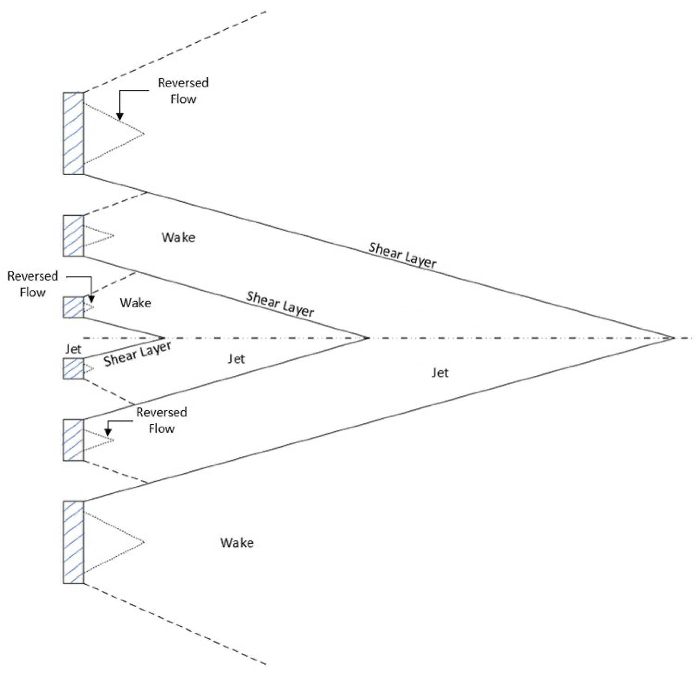
A conceptual diagram of the different flow regions induced by a fractal square grid is illustrated in Figure 5. Several typical flow regions are marked—jet, wake (reversed flow), and shear layers. The distribution of each flow feature is directly related to the number of length scales of the grid, with a bar causing a wake and an opening (space between the bars) causing a jet. A shear layer of steep velocity gradient occurs between the jet and wake region, which drives a significant increase in the momentum transport between these regions. A detailed view of the instantaneous streamlines of these different flow regions can be seen in Figure 6.
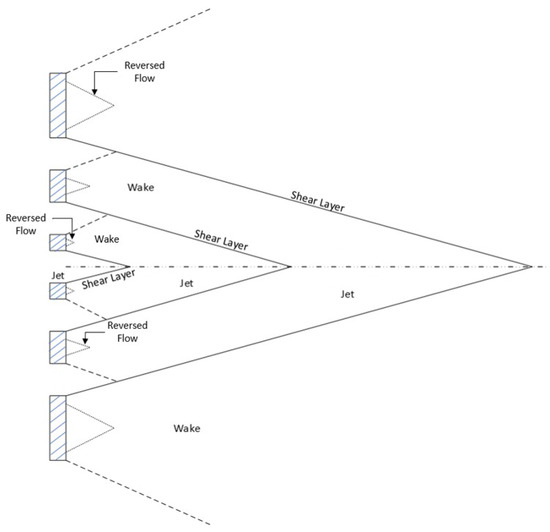
Figure 5.
Schematic of the different flow regions of the mean flow behind a fractal square grid.
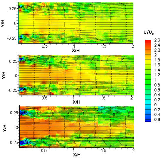
Figure 6.
Streamlines of the flow in the near wake of a grid at Re = 3400. FG1, FG2 and FG4 from top to bottom.
3.2. Effect of Multiple Scales on Turbulence Statistics
The change in the flow structure by the addition of multiple scales highlights the significance of interaction of the multiple scales, which is expected to affect the turbulence statistics, responsible for enhanced turbulent mixing and heat transfer rate. The streamwise, , vertical, , turbulence intensities and the Reynolds shear stress or RSS, , of the turbulent flow downstream of each fractal grid are examined in this section. They are critical quantities in the design of effective mixers, heat exchangers, and other flow control devices.
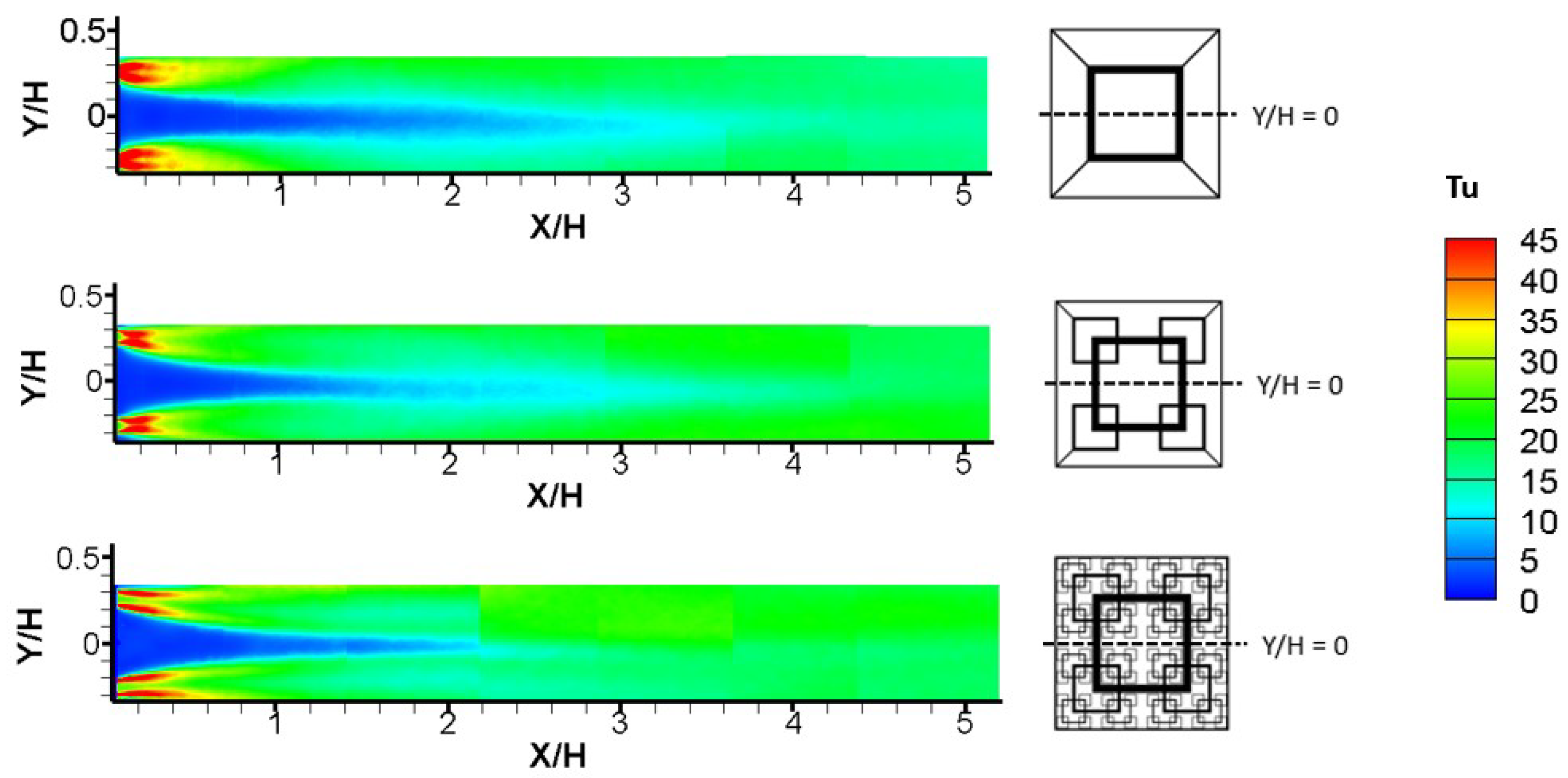
The contour plots of streamwise turbulence intensity , shown in Figure 7, exhibit common characteristics for the set of fractal grids. The turbulence intensity level varies remarkably for the different flow features identified in Section 3.1. Immediately behind the largest bars the highest is generated by the shear layers, reaching 45% for all fractal grids, where turbulence is reduced by half in the wake region. The central major jet, of the lowest less than 5%, is observed just behind the grid. The center line (y = 0) is subject to an increase from the lowest 0–5% to the moderate level of 20–25%. The spatial distribution of the behind the fractal square grids is consistent with that of previous DNS results in [16].
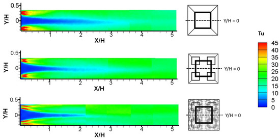
Figure 7.
Streamwise turbulence intensity (%) downstream of a fractal square grid at Re = 3400. FG1, FG2 and FG4 from top to bottom.
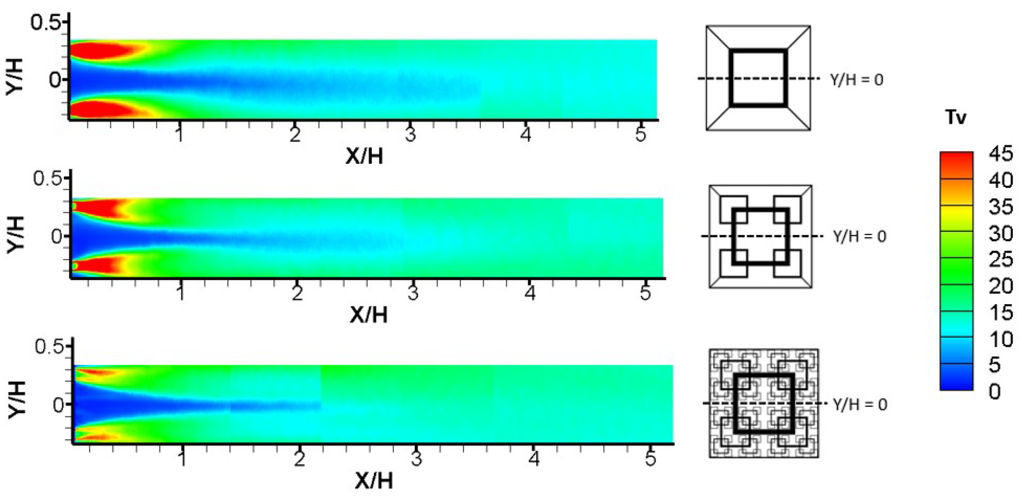
Clear differences are observed in the turbulence intensities in the induced flow; however, when including smaller scales gradually by systematically changing the iteration N, which have not been previously reported. The high immediately behind the grid displays an elongated trend as smaller scales present and interaction of multiple scales occur. Most distinctly, the centerline increases downstream of the grid at a different rate: at = 1, sharing a very similar level of 5% but at = 3 the reaches different level of 12.5% (FG1), 13.5% (FG2) and 20% (FG4). The flow behind the grids of N = 3 reported by [16], is similar to the current FG2 that falls in between the two extreme cases. The vertical turbulence intensity , in Figure 8, generally follows the same trend with respect to increasing N as that of , but with a lower magnitude. The level of with respect to , expressed in terms of the global isotropy parameter /, was found to match well with the results presented from previous PIV experiments [17].
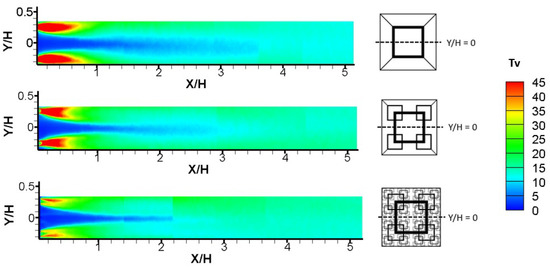
Figure 8.
Vertical turbulence intensity (%) downstream of a fractal square grid at Re = 3400. FG1, FG2 and FG4 from top to bottom.
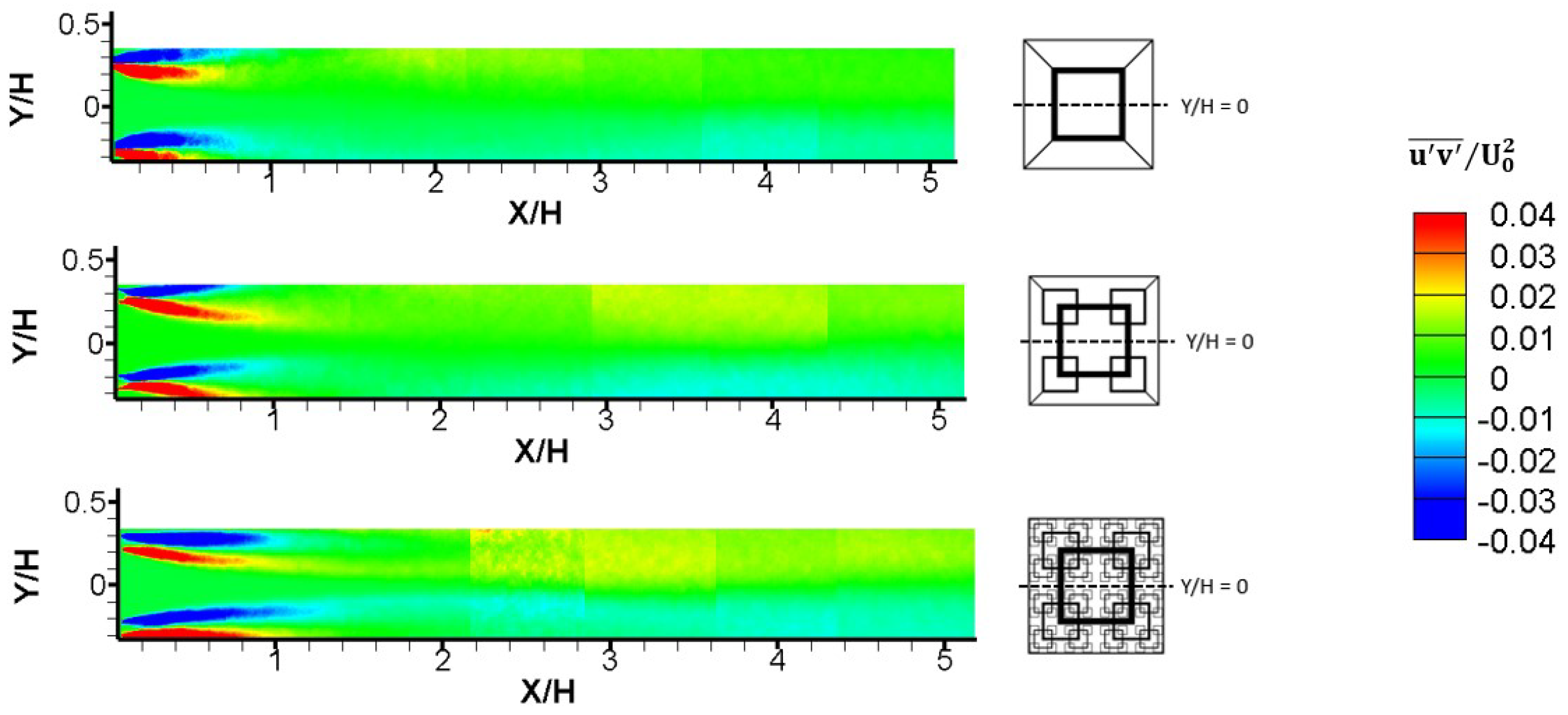
The distribution of the Reynolds shear stress (RSS) of turbulent flow induced by each fractal square grid is shown in Figure 9. The high magnitude of RSS immediately behind each grid, is associated with the strong shear between the jet and wake areas. The most intense region is more protracted as N increases, from = 0.6 for FG1 to = 1.0 for FG4. The RSS contours behind the FG4 show a notable increase along the shear layer between the large jet region and the outer adjacent wakes of the flow. This is attributed to the effect of the shear layers enhanced from the interaction between the multiple jet and wake regions surrounding the largest wakes. This effect can also be seen in the RSS distribution of the FG2, but not nearly as intense, which is evidenced that each additional scale (even the smallest ones) has a significant impact on the momentum transport in the flow. The increase in the momentum transport between the multiple jet and wake regions leads to enhanced turbulent mixing among different length scales.
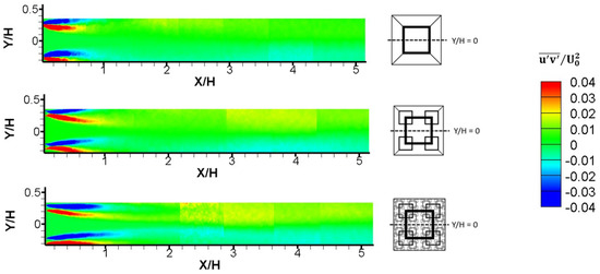
Figure 9.
Reynolds shear stress downstream of a fractal square grid at Re = 3400. FG1, FG2 and FG4 from top to bottom.
3.3. Revisit the Wake Interaction Length Scale Model
The wake interaction length scale model, introduced by Mazellier and Vassilicos (2010) [10], has been extensively used to predict how far downstream the centerline turbulence intensity reaches its peak value. This model relates the location of the peak streamwise turbulence intensity along the fractal grid’s centerline to the scales of the largest bars and :
where
and is the wake interaction length scale coefficient. The coefficient was originally determined to be a constant (0.45) based on data for fractal square grids having a similar blockage ratio [10]. However, it has been later realized to vary dramatically depending on grid geometry, inflow conditions and experimental facility, etc. [16,17,18,24,25]. The flow structure and turbulence statistics, in Section 3.1 and Section 3.2, evidenced the importance of the smaller scales in addition to the largest scale. Therefore, it is reasonable to account for the effects of smaller scales into the model to better predict .
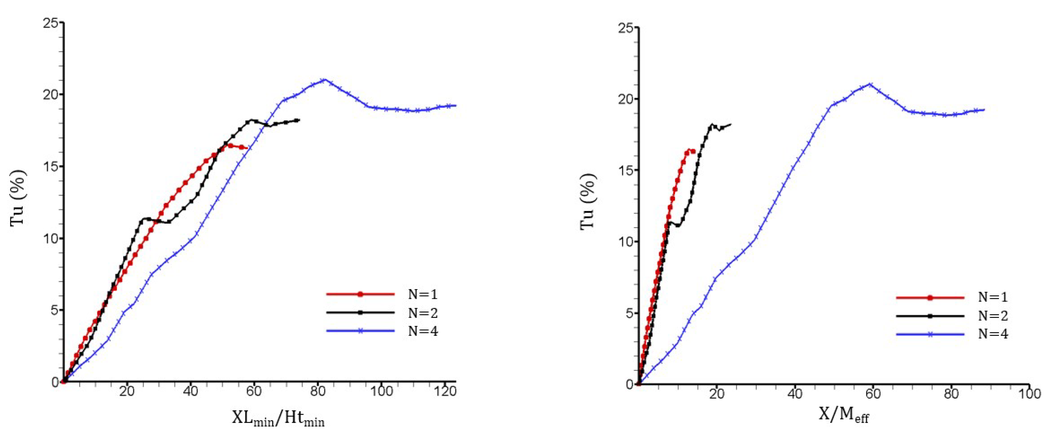
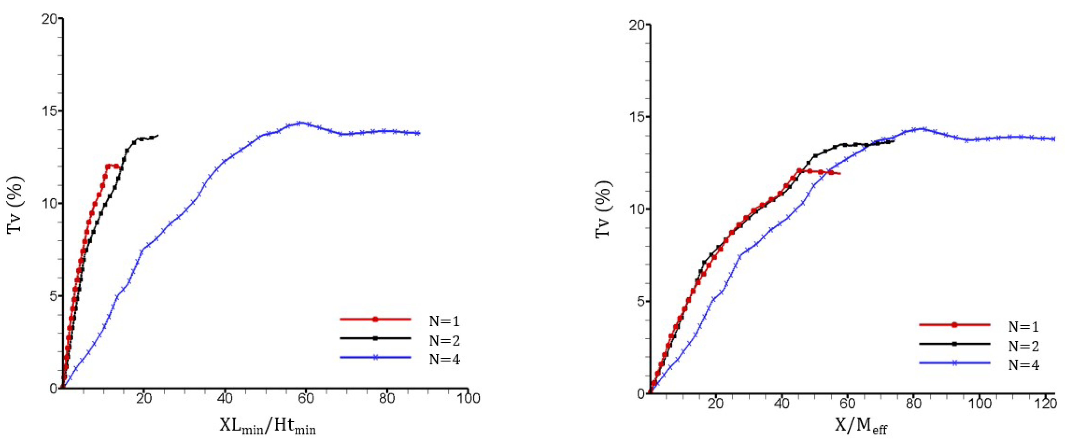
Using the framework of the wake interaction length scale model, we examined both the streamwise turbulence intensity and the vertcial turbulence intensity , at the center line, which are readily available via PIV tests. All fractal square grids have the same = 131.8 mm and = 11.7 mm, therefore = 1487.3 mm is kept constant in this study. By maintaining the same parameters of , , , and across the set of fractal square grids, the effect of additional fractal iterations can be determined.
The peak location and the peak turbulence intensities are summarized in Table 2. It can be seen that varies with fractal grids of the same dimensions of the largest bar or . Therefore, the wake interaction length scale model proposed by Mazellier et al. (2010) [10] does not seem to capture the trend of the turbulence intensity of the fractal square grids tested here, which are of identical and but different blockage ratio , varying with the number of fractal iterations, N.

Table 2.
Wake interaction length scales of the fractal square grids, FG1, FG2 and FG4.
Figure 10a and Figure 11a compare the centerline streamwise and vertical turbulence intensities, and , normalized by the smallest scale , for the set of fractal square grids. Figure 10a indicates that the normalized peak location shifts downstream gradually with additional scales being introduced (by varying the iteration, N). It is further reasoned that the location of the peak turbulence intensity is associated to not only the largest and smallest scales, but the complex interaction among them. To incorporate the effects of multiple scales and thereof interaction, the effective mesh size is considered. This scaling parameter accounts for every scale with the fractal perimeter P and the blockage ratio , instead of only the largest ([10]) or the smallest scales ([14]). When normalized by , shifts downstream with N varied from 1 to 4, following an exponential trend (Figure 10b). Therefore, we propose to include the effective mesh size explicitly into the model, to predict the change in location of with each additional scale relative to the single scale grid. The modified wake interaction length model is expressed as follows:
and
where is the location of peak turbulence intensity for grid of N iteration, and are the effective mesh size of the grids of the fractal iteration N and 1, and is the iteration scaling coefficient derived from the experimental data. grows exponentially with N for both the streamwise and vertical turbulence intensities, which is approximated in Equation (11). The modified model was tested using data presented by Nagata et al. (2017) [22]. To set the comparable base parameters of FG1, takes into account different blockage ratio and for fractal grids in this study and in [22]. It is interesting that values of are nearly the same for the current data and [22] summarized in Table 2, even though the two sets of grids are of different and . It is noted that the values of were obtained from the set of fractal square grids in our experiments and may not apply under other experimental conditions.
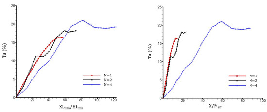
Figure 10.
Centerline streamwise turbulence intensity , normalized by the smallest scale (left) and the effective mesh size (right), downstream of each grid at Re = 3400.
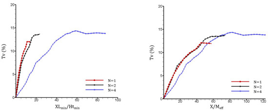
Figure 11.
Centerline vertical turbulence intensity , normalized by the smallest scale (left) and the effective mesh size (right), downstream of each grid at Re = 3400.
The exponential trend of the location with increasing N can be understood by the various dimensions of wakes generated by the different sized bars. First, the addition of smaller scales to the grid create multiple shear layers surrounding the wakes from the largest bars, leading to an elevated and elongated region of turbulence production. Furthermore, the additional scales enlarge the reversed flow areas immediately behind the grid, and the consequential increase in blockage ratio causes an acceleration of the flow through the center of the grid. The instantaneous streamlines of the flow behind the reversed flow areas, in Figure 6, diverge away from the grid centerline, and this trend is more intense as N increases. Such a trend has also been noted in the DNS simulations comparing grids with increasing thickness ratios and increasing blockage ratios [16]. Overall, this flow pattern leads to the tendency for the largest wakes to meet further downstream as N increases.
The magnitude of the peak centerline turbulence intensities was compared in order to determine the effect of the additional scales. Previously, the magnitude of the peak turbulence intensity was proposed to be proportional to / for fractal square grids, where is the drag coefficient of the largest bars of the grid [17]. Subsequent research focused on the largest scale being the dominant factor to determine the peak turbulence intensity magnitude, i.e., / [18,25]. This relation has shown to be true for both multi-scale and single-scale grids having different ratios of /. For example, single square grids with a higher ratio of / and lower blockage ratio are found to produce higher centerline turbulence intensities than fractal square grids [18]. While the drag of the bars is not directly measured here, it is assumed to be the same and will not change the results because the dimensions of the largest bars are identical for each grid.
Regarding the magnitude of the centerline turbulence intensities, our results show that each fractal grid generates a different level of turbulence along the centerline, for both the streamwise and vertical turbulence intensities, as summarized in Table 2. The peak centerline turbulence intensity follows approximately linear relationship, if normalized with the effective mesh size . We find that not only do the additional fractal scales influence the location of peak turbulence intensities, but their magnitude as well.
3.4. Pressure Drop across Fractal Square Grids
While the effect of multiple scales on the turbulence intensity and Reynolds shear stress is key to understand the dynamics of fractal grid-generated turbulence, the static pressure drop across the grid is essential to effectively implement such a flow control device in practical engineering applications. Therefore, the non-dimensional pressure drop at is chosen to compare the set of fractal grids. The level of pressure drop is primarily linked to the increasing blockage ratio, , with the increased fractal iteration N [23]. This is not different from what we understand regarding conventional or uniform grids. It would be difficult to quantitatively compare the magnitude of pressure drop in the current results with the previous wind-tunnel experiments, due to the difference in the inflow conditions and grid mounting mechanism. Nevertheless, the current results follow a similar trend to the previous experiments of a fractal square grid, single square grid, and conventional grid [18].
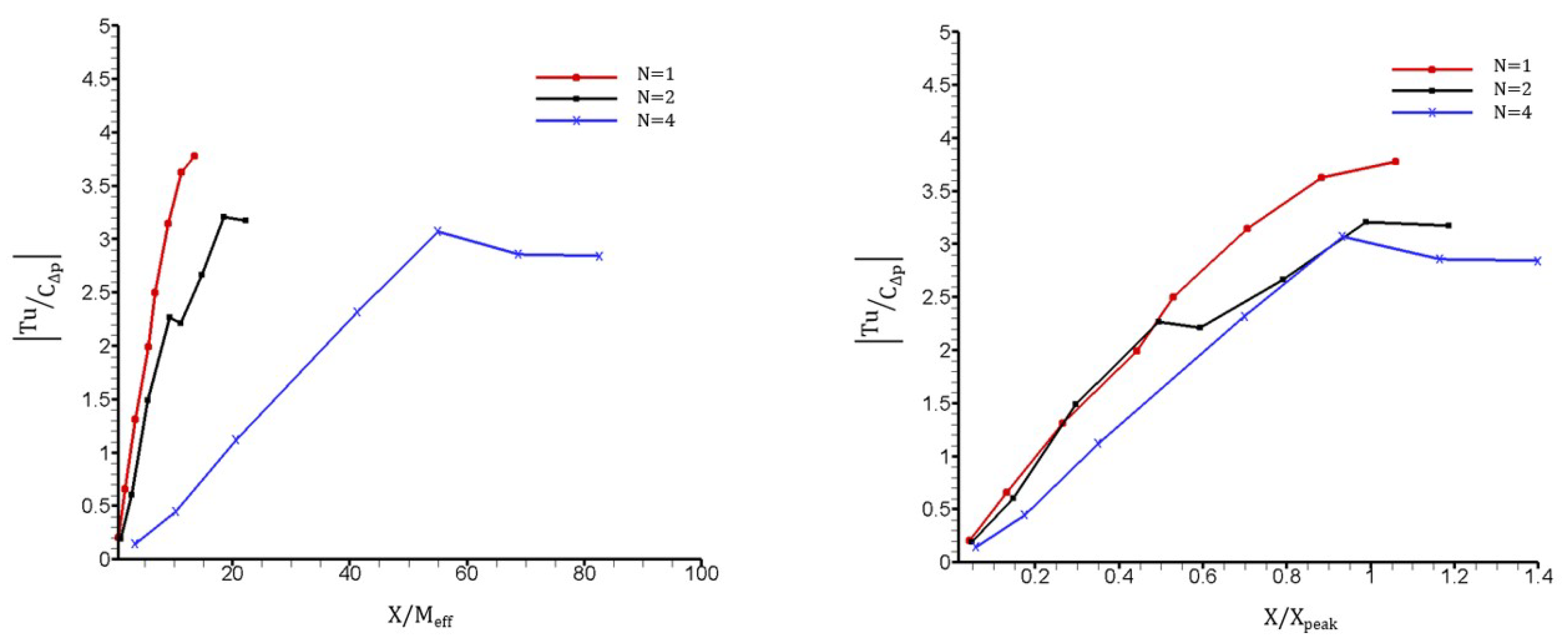
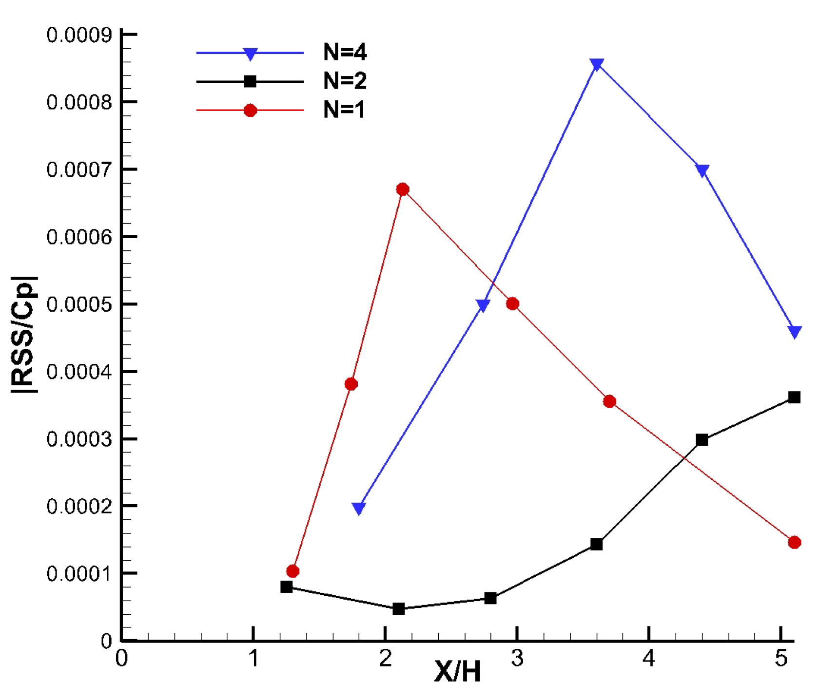
The ratio of the centerline turbulence intensity to the static pressure drop () of the set of fractal grids is in Figure 12. Immediately behind the grid, the ratio of the turbulence enhancement to the pressure loss of each fractal grid is comparable. However, further downstream the expense of pressure caused by the increase in blockage ratio (with increasing N) becomes more significant than the enhancement in the turbulence intensity. As the downstream location increases, there is a clear difference in the performance of each grid: the FG1 being most effective past = 0.5, with a 24% increase over that of FG4 at . Additionally, the ratio of Reynolds shear stress (RSS) to the pressure drop of the set of fractal grids is shown in Figure 13. RSS is another measure of momentum transport and turbulent mixing. Here RSS is averaged vertically using the PIV data in the measurement plane (Figure 9). Because the high values of RSS are not at the centerline, it has rarely been discussed in previous studies. The RSS downstream of FG4 is remarkably higher than FG1 further downstream. In particular, the maximum of RSS induced by FG4 is doubled that of the FG1.
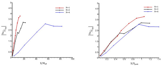
Figure 12.
Ratio of streamwise turbulence intensity to pressure drop at Re = 3400. The downstream distance X is normalized by (left) and (right).
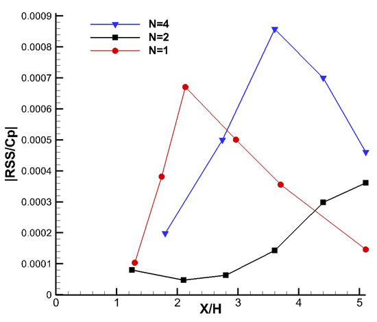
Figure 13.
Ratio of Reynolds shear stress to pressure drop at Re = 3400.
The ratio of RSS to the pressure drop suggests that the addition of the multiple scales creates a dramatic increase in the momentum transport, attributed to the interaction between the multiple jet and wake regions. When adopting fractal square grids to design flow mixers and heat exchangers, although the level of turbulent mixing or enhanced heat transfer is often the primary design parameter, it is desirable to the maintain the amount of energy to compensate pressure loss at a reasonable level, depending on specific objectives in engineering applications. It should be noted that, the trend of or varies downstream for each of the grids. In case that a particular distance to install a grid is specified, Figure 12 and Figure 13 are helpful to determine which grid best fits the requirement. Fractal grids with more scales would be advantageous if a longer distance is required for turbulence enhancement.
4. Conclusions
A set of fractal square grids are tested in water-tunnel experiments at Re = 3400, to determine the relationship between the fractal scales (varying with the fractal iteration N), the turbulence statistics of the generated turbulent flow and the pressure drop across the fractal grids. By keeping the largest bar dimensions of and constant, we focus on the effects of smaller fractal scales on turbulence statistics and pressure drop. Our contribution is summarized as follows:
- Detailed flow fields reveal the multiple jets, wakes and the shear layers in between, produced by the multiple scales of bars, are the fundamental flow physics that promote momentum transport in the fractal grid generated turbulence. The spatial distribution of turbulence intensities and the Reynolds shear stress suggest important effects of the additional fractal scales (with varying the iteration N) along with the largest scale.
- The wake interaction length scale model is revisited and modified to incorporate the effective mesh size and a new scaling coefficient , to reflect the effects of smaller scales and the interaction among these scales. increases exponentially with the fractal iteration N, which may be affected by fractal grid configuration, inflow turbulence level and global/local Reynolds numbers.
- The effectiveness of a fractal square grid is assessed by the ratio of turbulence intensity to the pressure drop and the ratio of Reynolds shear stress to the pressure drop. When using the fractal square grids as the passive flow control devices, the variation of such ratios with respect to the distance from the grid should be considered based on design specifics. Fractal grids with more scales would be advantageous if a longer distance is required for turbulence enhancement.
In view that the flow measurements are only conducted in the single center plane of the generated turbulent flow, conclusions need to be validated with complete three-dimensional flow statistics. Correspondingly, the modified wake interaction length model is to be further tested with other computational or measurement data at different Reynolds numbers.
Author Contributions
A.O. and W.Z. conceived and designed the experiments; A.O. and J.T. performed the experiments; A.O. and W.Z. analyzed data and discussed the results; All contributed to writing and revision of the paper.
Acknowledgments
This research is supported by the Faculty Startup Funds from the Office of Research at the Cleveland State University. The authors would like to acknowledge the 3D printing lab for creating the test models and David Epperly for his efforts in helping experimental setup. J.T.
Conflicts of Interest
The authors declare no conflicts of interest.
References
- Critten, D.L. Fractal dimension relationships and values associated with certain plant canopies. J. Agric. Eng. Res. 1997, 67, 61–72. [Google Scholar] [CrossRef]
- De Langre, E. Effects of wind on plants. Ann. Rev. Fluid Mech. 2008, 40, 141–168. [Google Scholar] [CrossRef]
- Bai, K.L.; Meneveau, C.; Katz, J. Near-wake turbulent flow structure and mixing length downstream of a fractal tree. Bound.-Layer Meteorol. 2012, 143, 285–308. [Google Scholar] [CrossRef]
- Bai, K.L.; Meneveau, C.; Katz, J. Experimental study of spectral energy fluxes in turbulence generated by a fractal, tree-like object. Phys. Fluids 2013, 25, 110810. [Google Scholar] [CrossRef]
- Bai, K.L.; Katz, J.; Meneveau, C. Turbulent flow structure inside a canopy with complex multi-scale elements. Bound.-Layer Meteorol. 2015, 155, 435–457. [Google Scholar] [CrossRef]
- Debnath, L. A brief historical introduction to fractals and fractal geometry. Int. J. Math. Educ. Sci. Technol. 2006, 37, 29–50. [Google Scholar] [CrossRef]
- Kenney, W.A. A method for estimating windbreak porosity using digitized photographic silhouettes. Agric. For. Meteorol. 1987, 39, 91–94. [Google Scholar] [CrossRef]
- Venugopal, V.; Porté-Agel, F.; Foufoula-Georgiou, E.; Carper, M. Multiscale interactions between surface shear stress and velocity in turbulent boundary layers. J. Geophys.Res. Atmos. 2003. [Google Scholar] [CrossRef]
- Kang, H.S.; Dennis, D.; Meneveau, C. Flow over fractals: Drag forces and near wakes. Fractals. 2011, 19, 387–399. [Google Scholar] [CrossRef]
- Mazellier, N.; Vassilicos, J.C. Turbulence without Richardson-Kolmogorov cascade. Phys. Fluids 2010, 22, 1–25. [Google Scholar] [CrossRef]
- Goh, K.H.H.; Geipel, P.; Hampp, F.; Lindstedt, R.P. Flames in fractal grid generated turbulence. Fluid Dyn. Res. 2013, 45, 061403. [Google Scholar] [CrossRef]
- Verbeek, A.A.; Bouten, T.W.F.M.; Stoffels, G.G.M.; Geurts, B.J.; van der Meer, T.H. Fractal turbulence enhancing low-swirl combustion. Combust. Flame 2015, 162, 129–143. [Google Scholar] [CrossRef]
- McClure, S.; Kim, J.J.; Lee, S.J.; Zhang, W. Sheltering effects of multi-scale fractal wind fences. J. Wind Eng. Ind. Aerodyn. 2017, 163, 6–14. [Google Scholar] [CrossRef]
- Hurst, D.; Vassilicos, J.C. Scalings and decay of fractal-generated turbulence. Phys. Fluids. 2007, 19, 035103. [Google Scholar] [CrossRef]
- Stresing, R.; Peinke, J.; Seoud, S.; Vassilicos, J.C. Defining a new class of turbulent flows. Phys. Rev. Lett. 2010, 104, 194501. [Google Scholar] [CrossRef] [PubMed]
- Laizet, S.; Vassilicos, J.C. DNS of fractal-generated turbulence. Flow Turbul. Combust. 2011, 87, 673–705. [Google Scholar] [CrossRef]
- Gomes-Fernandes, R.; Ganapathisubramani, B.; Vassilicos, J.C. Particle image velocimetry study of fractal-generated turbulence. J. Fluid Mech. 2012, 711, 306–336. [Google Scholar] [CrossRef]
- Melina, G.; Bruce, P.J.K.; Vassilicos, J.C. Vortex shedding effects in grid-generated turbulence. Phys. Re. Fluids 2016, 1, 044402. [Google Scholar] [CrossRef]
- Laizet, S.; Nedić, J.; Vassilicos, J.C. The spatial origin of −5/3 spectra in grid-generated turbulence. Phys. Fluids. 2015, 27, 065115. [Google Scholar] [CrossRef]
- Cafiero, G.; Discetti, S.; Astarita, T. Heat transfer enhancement of impinging jets with fractal-generated turbulence. Int. J. Heat Mass Transf. 2014, 75, 173–183. [Google Scholar] [CrossRef]
- Cafiero, G.; Castrillo, G.; Greco, C.S.; Astarita, T. Effect of the grid geometry on the convective heat transfer of impinging jets. Int. J. Heat Mass Transf. 2017, 104, 39–50. [Google Scholar] [CrossRef]
- Nagata, K.; Saiki, T.; Sakai, Y.; Ito, Y.; Iwano, K. Effects of grid geometry on non-equilibrium dissipation in grid turbulence. Phys. Fluids. 2017, 29, 015102. [Google Scholar] [CrossRef]
- Laizet, S.; Vassilicos, J.C. Stirring and scalar transfer by grid-generated turbulence in the presence of a mean scalar gradient. J. Fluid Mech. 2015, 764, 52–75. [Google Scholar] [CrossRef]
- Laizet, S.; Vassilicos, J.C. Fractal space-scale unfolding mechanism for energy-efficient turbulent mixing. Phys. Rev. E 2012, 86, 1–11. [Google Scholar] [CrossRef] [PubMed]
- Melina, G.; Bruce, P.J.K.; Hewitt, G.F.; Vassilicos, J.C. Heat transfer in production and decay regions of grid-generated turbulence. Int. J. Heat Mass Transf. 2017, 109, 537–554. [Google Scholar] [CrossRef]
© 2018 by the authors. Licensee MDPI, Basel, Switzerland. This article is an open access article distributed under the terms and conditions of the Creative Commons Attribution (CC BY) license (http://creativecommons.org/licenses/by/4.0/).


