1. Introduction
One of the main challenges in the manufacturing sector is developing more efficient processes, aiming to reduce both energy consumption and the wastage of raw materials. This endeavor will facilitate the decarbonization of the industry and enable compliance with international climate targets.
Numerous industrial sectors require procedures that involve the utilization of liquids for purposes such as cleaning, cooling, lubrication, and coating. These liquids must be entirely or partially eliminated once their intended function has been fulfilled, as inadequate drying or wiping can significantly increase product rejection rates. Consequently, the development of more efficient drying and wiping systems to avoid product rejection, while minimizing energy consumption, is a crucial objective for most industries [
1].
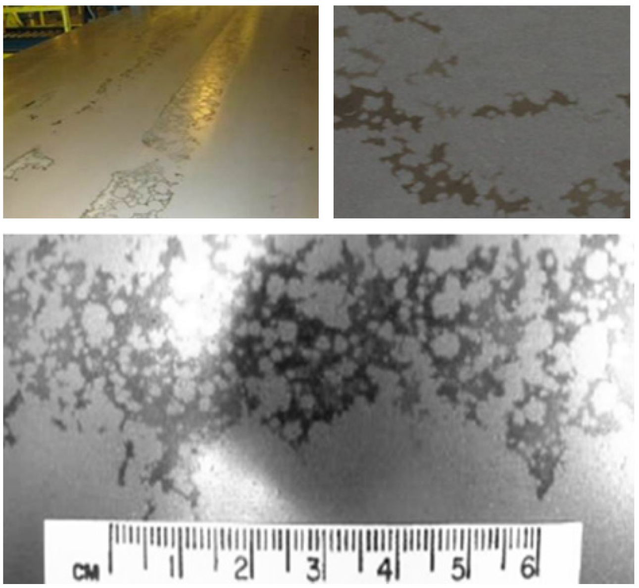
In cold rolling mills, insufficient drying of the emulsion used for cooling and lubrication can lead to the formation of emulsion stains (
Figure 1). These stains typically appear when unwinding strips after being coiled with liquid residues on their surfaces. The hues of these stains vary from brown to black, exhibiting a pronounced prevalence at strip edges. Although this issue is primarily aesthetic, it is unacceptable in sectors such as the automotive and household appliance industries. Indeed, this is a common cause for product rejection, resulting in significant financial losses. For illustrative purposes, the rejections attributable to this particular defect within a conventional cold rolling mill could amount to €1 million per year. Consequently, given the critical role of drying systems in these processes, drying systems are typically over-engineered, leading to excessive energy consumption.
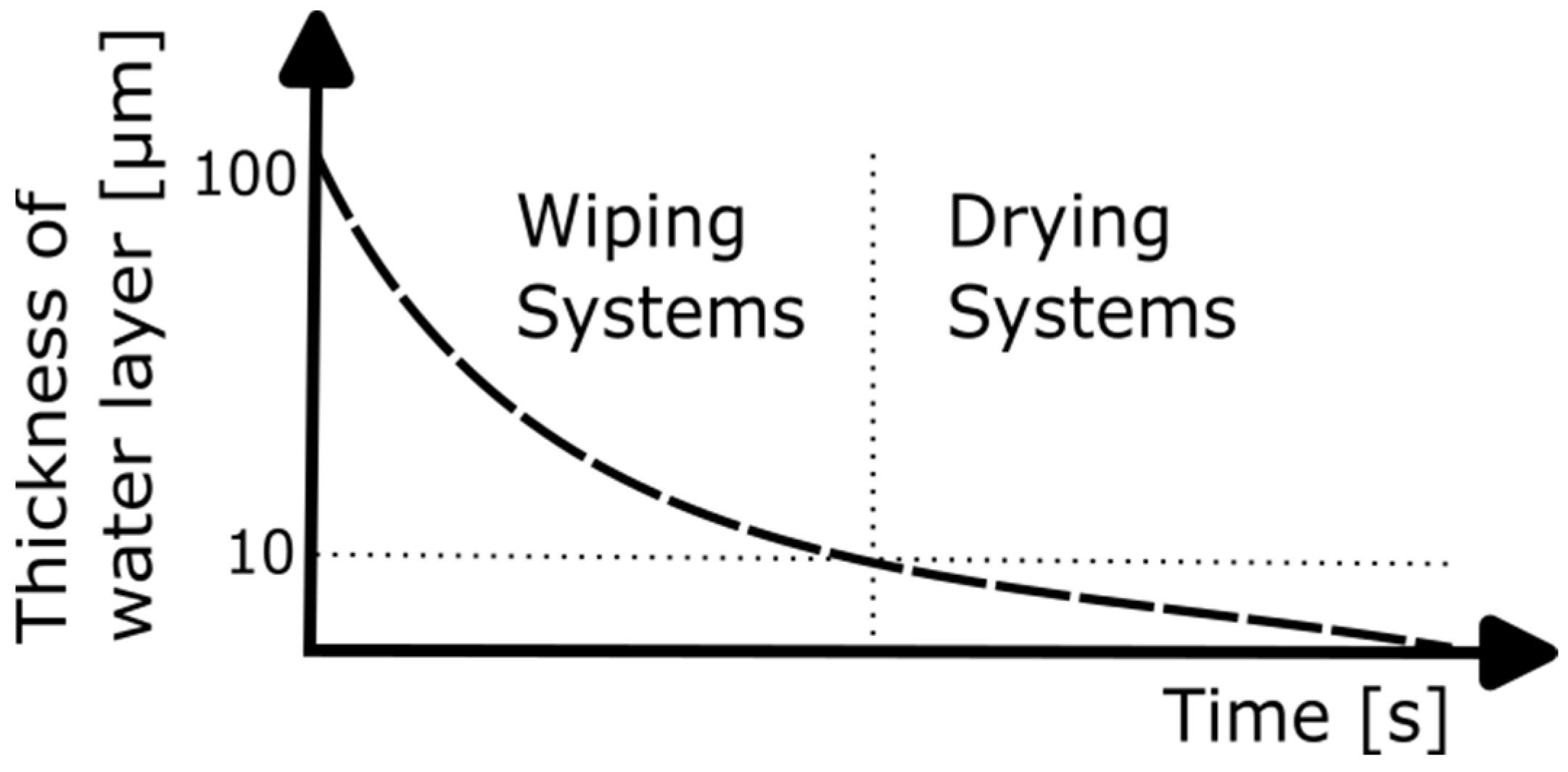
Currently, methodologies for liquid extraction systems can be categorized into two main types: wiping systems and drying systems. The selection between these methods is largely determined by the thickness of the liquid layer that requires elimination (
Figure 2). On the other hand, both types of systems are often employed in certain production lines [
2].
In wiping systems, air blowers and wringer rollers are commonly used in various manufacturing sectors, including steel production, microelectronics, pharmaceuticals, and display manufacturing, among others. Focusing on gas blowers, a fundamental method for removing liquid from surfaces involves the utilization of planar jets, which are positioned orthogonally [
3], inclined [
4,
5], or parallel [
6] to the surface. These devices are widely employed in many processes for three main purposes:
Moisture drying, using hot air. For example, for the food or paper industry [
2].
Obtaining products with a specific coating thickness, such as in hot-dip galvanizing lines [
7,
8,
9] or solar cells [
10].
Removing fluids from a surface, such as in cold rolling or tinplate manufacturing lines [
13].
The main differences are the existence of film breakage [
14] or using cold air in the third case.
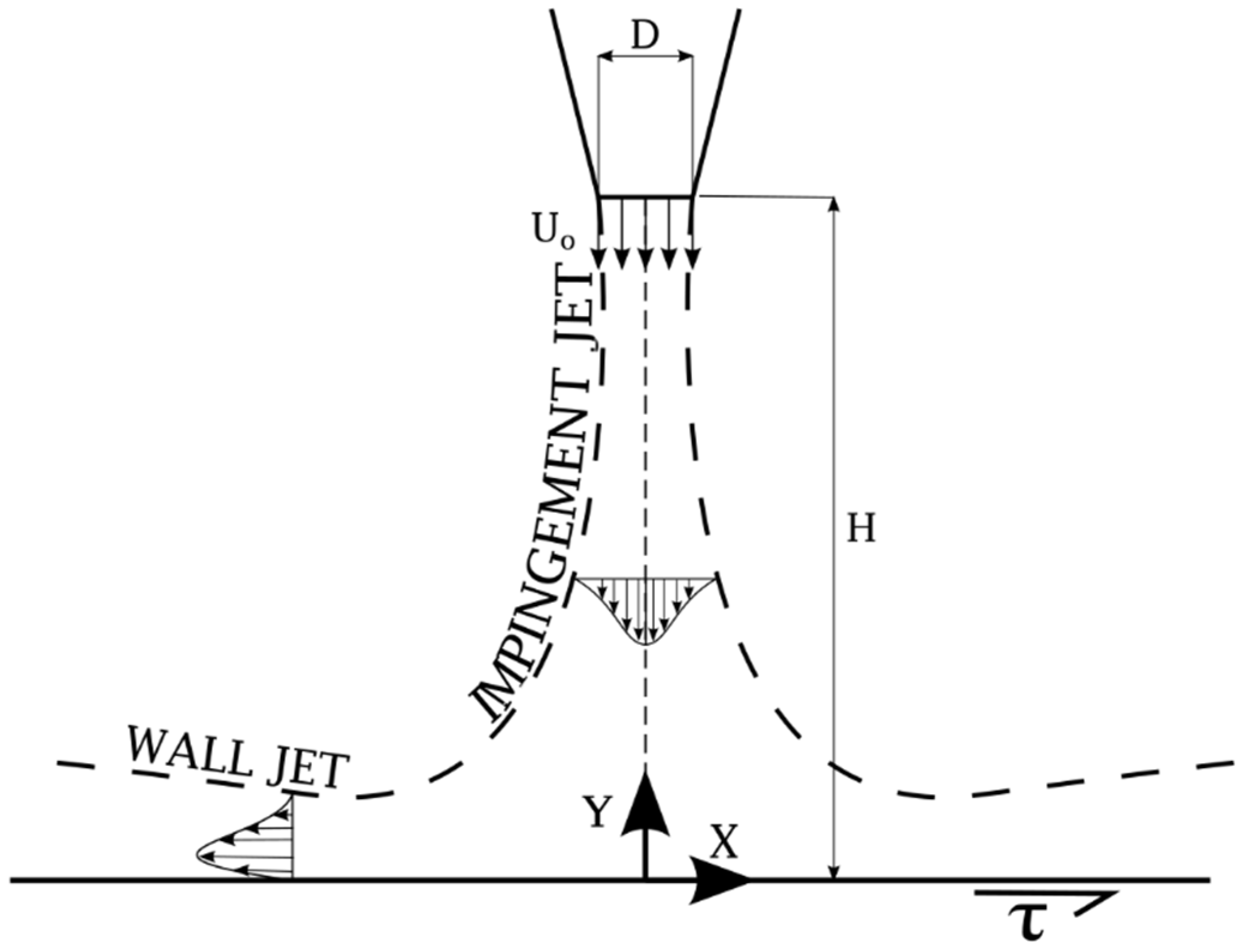
The particular case of a perpendicular impinging planar jet has been extensively studied by several authors. All the works related to this topic mention two different regions of the jet: the impinging jet and the wall jet, as can be seen in
Figure 3, where
is the nozzle width,
is the velocity at the nozzle outlet,
is the blowing distance, and
τ is the wall shear stress.
The earliest bibliography related to perpendicular impinging planar jets was primarily focused on developing correlations to analytically reproduce the velocity, pressure and shear stress field associated with the jet. These correlations were subsequently employed in analytical models to predict liquid thickness in hot-dip galvanized lines, assessing heat transfer coefficients, etc. Multiple references can be found on this topic, e.g., [
15,
16].
Although basic research on this area continues, most efforts have branched out in different directions. Significant attention has been devoted to analyzing the interaction between the jet and liquid free surfaces [
17,
18,
19]. Additionally, many studies have explored the design of complex nozzles aiming to reduce flow instabilities and improve performance [
20,
21]. And other researchers have diverted their interest to achieve a better understanding of the flow structures associated with the intrinsic instabilities of a free jet [
22,
23,
24,
25,
26,
27].
When an air jet impinges on a surface, its operation is inevitably related to the impingement pressure distribution generated on the surface. Ref. [
16] conducted an investigation into the impingement pressure distribution associated with a planar jet across various
ratios (
Figure 3). It was concluded that an increase in the
ratio results in an expansion of the impingement region’s width, while reducing the maximum pressure value. This phenomenon occurs such that the integral area beneath the pressure curve, which represents the force per unit width, remains nearly constant to maintain equilibrium with the momentum of the jet. Consequently, it is evident that all parameters exhibit adherence to a dimensionless profile. Furthermore, multiple researchers indicate that the maximum impingement pressure is independent of the Reynolds number [
16,
28].
However, concerning wiping systems employed in industrial settings, it should be noted that most of the commercially available air knives are characterized by a hollow internal structure. It is crucial to understand that these systems are commonly engineered with an emphasis on simplicity: slots machined into cylindrical tubes or bent plates accompanied by welded side covers. The focus is on reducing both manufacturing and maintenance expenses. Additionally, these systems are frequently retrofitted into existing facilities, requiring modifications that have not been rigorously validated by the manufacturers, potentially leading to operational failures [
29].
As noted, emulsion stains appear mainly at the strip edges, indicating a malfunction of the air knife in those areas. Although there are studies that analyze tridimensional effects within the planar jet created by an air knife [
22,
23,
24,
25,
26,
27], they are mostly focused on turbulent instabilities. Therefore, there is no available information in the literature regarding the performance at the side of a finite planar jet.
This investigation analyzes a commercial air knife, focusing on the performance at the lateral sides where deviations from the two-dimensional performance are expected. An experimental campaign was conducted to measure impingement pressure profiles along the entire span of the air knife, specifically encompassing areas that extend beyond the vertical projection of the air knife itself. To the authors’ knowledge, this subject has not been previously investigated and could significantly enhance existing knowledge of air knife performance, as it enables researchers to make reliable predictions in regions where traditional two-dimensional approaches are not fully adequate.
The results indicate that the impingement pressure fields beyond the lateral boundaries of a finite air knife follow a similarity law based on an exponential correlation. This formulation, in combination with established correlations for planar jets, enables the prediction of impingement pressure profiles associated with a finite-length air knife. The output of this work could lead to potential improvement in the efficiency of any finite air knife system, as well as support the development of more reliable analytical models for industrial processes.
Note that all the experimental measurements are available at the University repository [
30].
2. Experimental Set-Up and Measurement Methodology
2.1. NCRig Facility
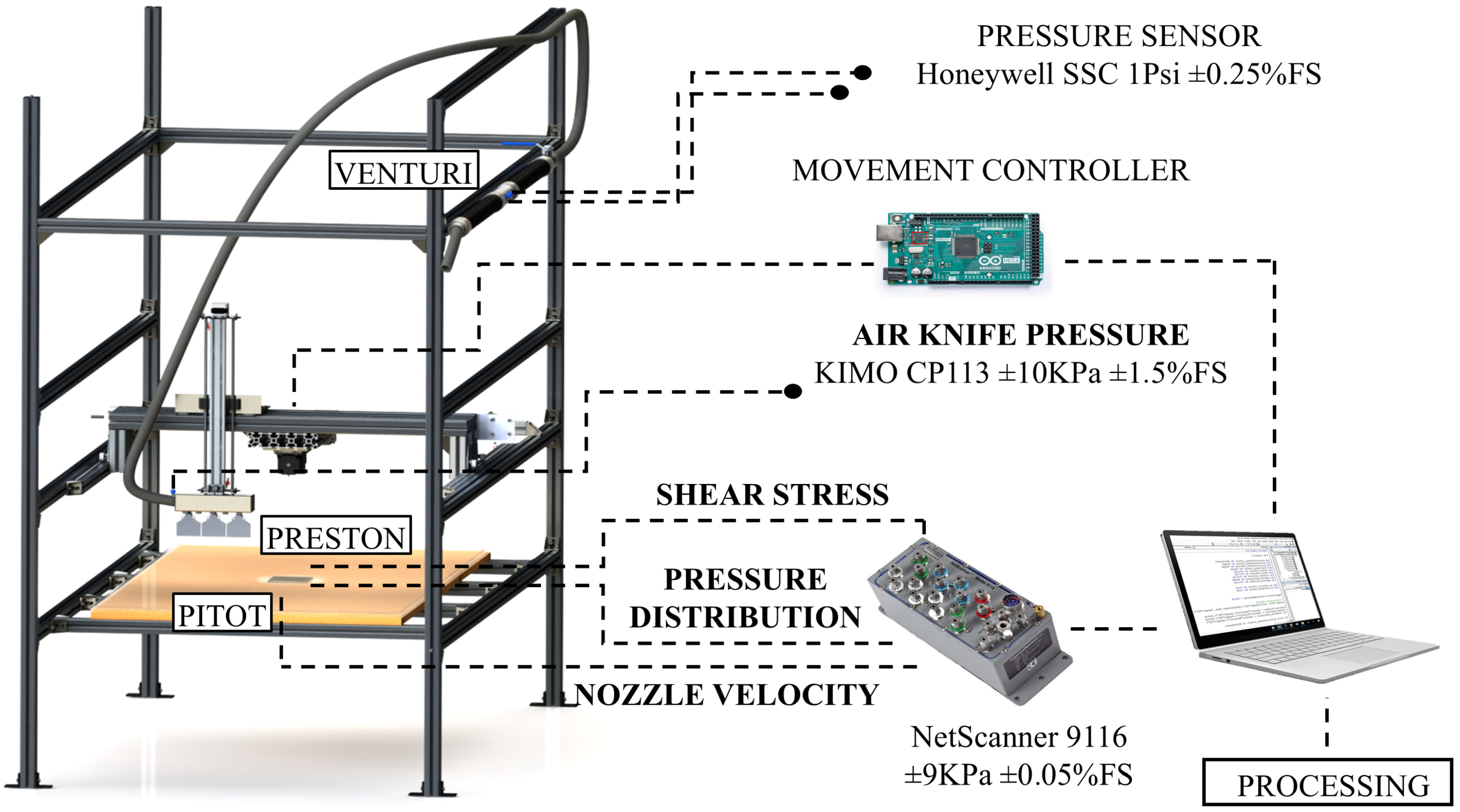
A test bench (
Figure 4), named the Nozzle Characterization Rig (NCRig), was built at the Fluid Mechanics Laboratory of the University of Oviedo in order to measure pressure profiles and shear stress distributions of wiping systems, including impinging planar jets.
The NCRig is equipped with a three-axis () movement system aligned by guides and driven through spindles by bipolar stepper motors (NEMA23 (Usongshine, Shenzhen, China) for the axis and NEMA 17 (Shenzhen Longruner Digital Co., Ltd., Shenzhen, China) for the and -axis). For the motor control, drivers DRV8825 were employed. In addition, two endstop switches (WJMY) were implemented per axis to limit the movement. For the whole system control, an open-source hardware composed of an Arduino equipped with a Shield RAMPS 1.4 was used.
The installation is fed by a stationary electric compressor ER-15 from Betico (Vitoria-Gasteiz, Spain), which offers regulation capabilities ranging from 0.5 to 2.5 m3/min and pressure adjustments between 6 and 13 bar; it also encompasses instrumentation for the acquisition of impingement pressures, flow rates, velocities, and shear stress values.
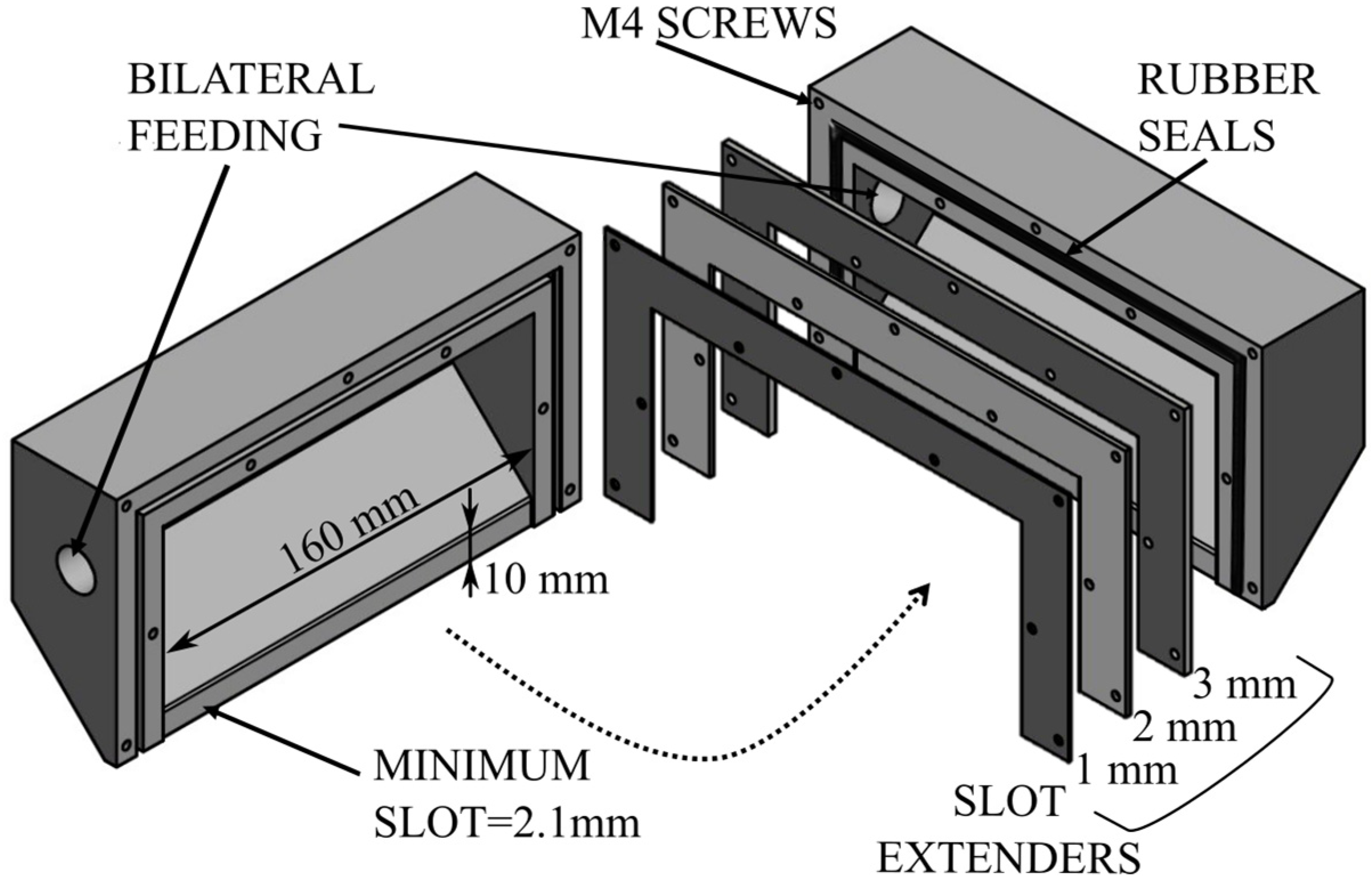
For this work, an air knife (see
Figure 5), with a span (
) of 160 mm and a nozzle width (
) of 2.1 mm, was used for the tests. The ratio
, according to the literature [
16], guarantees a planar jet at the midspan. This air knife is characterized by two main features:
It is double-fed. This configuration was chosen since previous studies on air knives fed from one side showed a clear deficit in uniformity in the velocity field at the nozzle outlet [
29]. The double-fed configuration presents smaller deficits [
31,
32] and, in this work, a non-frontal arrangement of both inlets was selected.
Since this work is focused on industrial applications, the model emulates a conventional commercial configuration. It was constructed without internal honeycombs, which would be expected to increase turbulence in the shear layers, leading to larger flow entrainment and faster jet spreading.
In all the experimental assessments conducted for this investigation, the planar jet was oriented perpendicularly to the surface. Furthermore, a methacrylate plate measuring 1200 × 600 mm2 was situated at the center of the rig to serve as the impingement surface for the experimental trials.
2.2. Pressure Measurements
The results obtained from the tests have been made dimensionless using the classical formulation in function of the dynamic pressure at the nozzle outlet: . Note that is the velocity measured at the air knife midspan.
was assessed through two distinct methodologies: (1) Assuming stagnation within the air knife and applying Bernoulli’s principle to the static pressure present, and (2) employing a simple Pitot tube (G27-gauge needle) at the nozzle’s outlet. Although the discrepancies in values remain below 2%, the authors ultimately resolved to utilize the measurement obtained from the Pitot tube, as the absence of a honeycomb structure within the air knife could potentially result in an incomplete stagnation zone surrounding the static pressure tap.
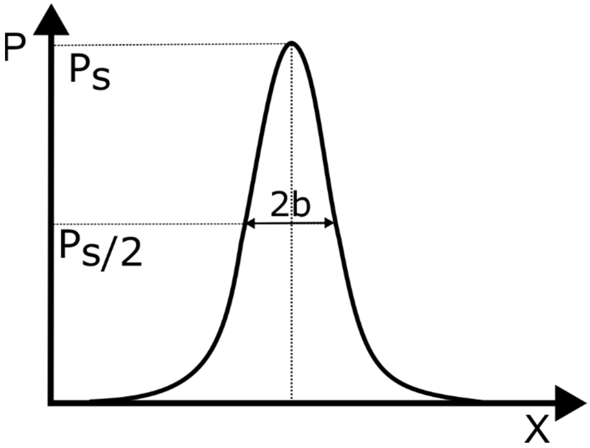
The width of the pressure profile is an additional parameter utilized in the post-processing phase.
Figure 6 illustrates the method employed to determine this measurement. It is defined from the position at which the pressure value equals one-half of the maximum value recorded at the impinging point. The values for each case are reported in
Table 1.
The measurements were made at different blowing distances
(
Figure 3) within the range of [4–22.4], whereas the static pressure inside the air knife was set to
= [1, 2, 3] kPa. These
values drive the jet to reach velocities
and the Re number to be in the range of 6000–11,000. Note that the Re is defined in terms of the nozzle width (
) and
. The temperature at the nozzle outlet was also measured to assess the air density.
Table 1 summarizes the operational parameters used in the tests.
Flow conditions in
Table 1 fall within the range encountered in industrial processes, as reported in the literature. Reference [
31] indicates that, in galvanizing lines, gas jet velocities lie between 50 and 200 m/s. Reference [
33] reports the use of velocities around 100 m/s in the manufacturing of organic and hybrid semiconductor thin films, and, in the context of perovskite solar cell fabrication, ref. [
34] employs air knives operating at velocities below 40 m/s.
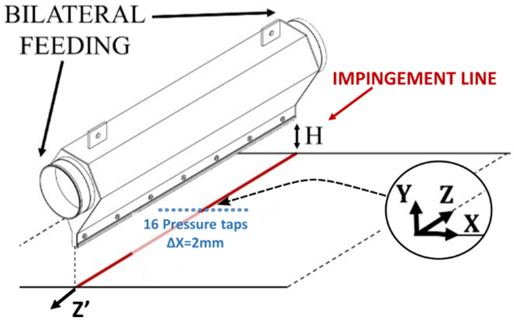
Impinging pressure profiles were obtained using the 16 pressure taps of 0.9 mm in diameter, separated by 2 mm from each other, along
direction (
Figure 7). The air knife was systematically maneuvered along the
-axis to make measurements every 0.25 mm, thus having 128 measurement points in
in each
-position. To evaluate the pressure field throughout the entire span of the air knife, the movement system adjusted the air knife by 1 mm between measurements along
direction at the lateral sides, while larger displacements were implemented as the system approached the midspan.
Measurements were taken along the entire length of the nozzle projection, extended by an additional 40 mm, with the first and last measurement positions located 20 mm outward from the projection. Data at each measurement point was recorded for a minimum of 30 s in order to: (a) discard the initial five seconds and avoid transient effects caused by the displacement of the air knife, and (b) perform time-averaging to smooth out any unsteadiness associated with the vorticity at the nozzle outlet.
2.3. Instrumentation
A 16-port pressure scanner (NetScanner 9116 (Pressure Systems, Inc., Hampton, VA, USA), range of ±9 kPa and error of ±0.05% FS) was employed to measure the static pressures at the pressure taps to determine the impingement pressure distribution. The sampling frequency of the scanner was set to 100 Hz throughout the entire study.
The static pressure inside the air knife was assessed by a KIMO CP113 (KIMO Instruments, Montpon-Ménestérol, France) with a measurement range of ±10,000 Pa and an accuracy of ±1.5% of the reading plus ± 30 Pa.
An uncertainty analysis of the measurements was carried out following the Kline methodology [
35], taking into account the resolution of the equipment used to obtain the pressure.
Table 2 shows the relative uncertainties of each variable for the dimensionless values of pressure impingement. It is clear from the data that the measurement of the outlet velocity
, reaching 1.5% of relative uncertainty, constitutes the most significant contribution to the overall uncertainty.
3. Results and Discussion
3.1. Impingement Pressure Profiles at Midspan
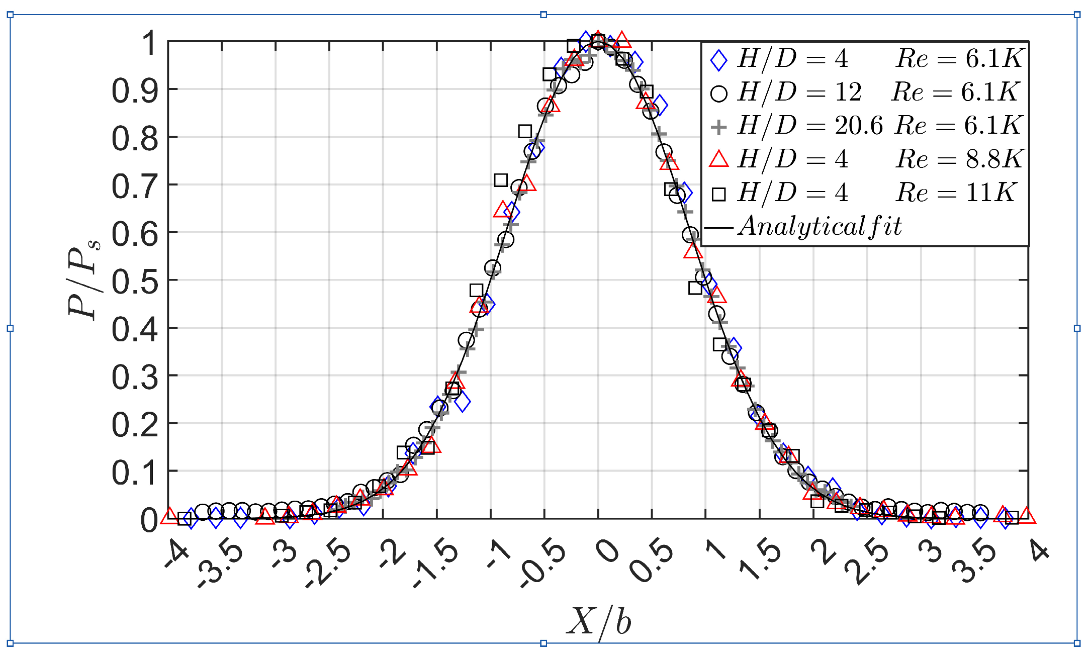
Figure 8 shows the corresponding impingement pressure profiles for some of the cases tested, encompassing three
and three different
in the air knife (see
Table 1). As anticipated, the results follow the established Gaussian distribution when normalized by the stagnation pressure recorded in each profile. This correlation has been documented in numerous prior studies as:
where both the coefficient
and the function
depend on the reference. Note that from a physical standpoint,
can be interpreted as a measure of the lateral momentum redistribution induced by turbulent mixing and is therefore directly related to jet spreading and air entrainment mechanisms. Taking into account the absence of honeycomb, it should be expected that
values would be smaller than in the literature, especially those where the air knife is involved with numerous elements (perforated plates, screens, etc.) to reduce turbulence, e.g., [
15,
16]. However, all the results of this investigation align remarkably well with the coefficients provided by [
16],
, reaching an agreement of
coefficient of 0.9812. The fact that the dimensionless impingement pressure field appears to be unaffected involves the lack of honeycomb, which is partially compensated for. Here, the authors consider that the ratio between the lip length and the nozzle gap (
) is enough to suppress transversal velocities and reach a stabilized top-hat velocity profile [
36].
On the other hand, the large ratio between the lip length and the nozzle gap has a side effect. While it stabilizes the flow, it also promotes a more pronounced boundary layer growth, generating viscous losses and increasing the displacement thickness along the lips, which reduces the jet’s core velocity.
As a consequence, downstream of the nozzle exit, the width of the jet increases while the potential core length diminishes [
16,
26], leading to a reduction in the stagnation pressure. Consequently, when comparing the results to the literature, an underestimation of the maximum impingement pressure
is observed. It increases with
and reaches a deficit of 10% for the largest
tested.
According to [
16], the influence of the upstream turbulence is appreciated from distances
, which is in agreement with the results of this work. Although further investigations should be made to evaluate the dependency on the level of upstream turbulence and lip length, the data obtained in this work, for
, follow the proposed fitting expression:
.
From these findings, it is concluded that the absence of the honeycomb is affecting the value of the maximum impingement pressure, but the dimensionless profile for all the cases is unaffected. Therefore, this expression is recommended for applications where no honeycomb is incorporated within the air knife, provided the nozzle geometry is such that a top-hat velocity profile is reached.
In addition, it is also seen that there is independence of the Reynolds number within the ranges analyzed (
Table 1) in the three
distances studied, in agreement with many references, e.g., [
15,
16].
3.2. Span-Wise Distribution of Maximum Impingement Pressure
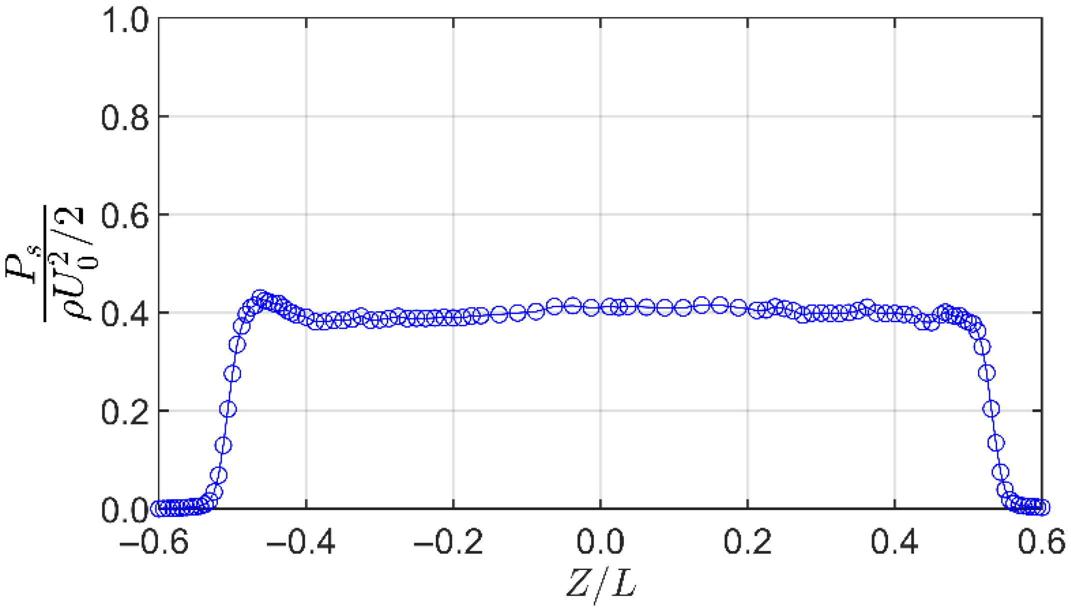
Figure 9 is focused on one of the objectives of this work. It shows the evolution of the maximum impingement pressure registered during the scanning process along the impingement line situated on the
OZ-axis for the specific case of
and
. As expected, the performance is almost 2D within the central 90% of the air knife. However, there is a local bump on the left side across all cases, resulting in a deviation that ranges from 4% to 6% relative to the midspan, depending on the case. It was determined that it was created by a change in the feeding pressure because it appears in all the tests and in the same location. The width of the air knife was checked by a caliper, finding that the difference in width along the whole span was less than 2.5%. Thus, since similar deviations are shown in [
31] for a double-fed air knife, the hypothesis of the authors is that this deviation is related to the absence of any honeycomb and the interaction between the inlet jets, which are placed just in front of each other. Nevertheless, the authors acknowledge that further studies in this research line should corroborate this hypothesis. Despite the pressure differential remaining below 6%, it is suggested that the design methodologies employed by the majority of air knife manufacturers (not including a honeycomb) may lead to certain deviations from the ideal 2-D operational performance.
The degree of uniformity in the pressure field, closely related to the double-fed air knife, must be taken into account when analyzing the forthcoming results. Note that any deviation from this degree of uniformity, e.g., in single-side-fed air knife, would lead to results different from those reported in the following sections.
3.3. Impingement Pressure Profiles at Air Knife Lateral Boundaries
As shown in
Figure 9, the gradients at the air knife sides are unexpectedly large. The extent of the jet’s impingement is merely 10% greater than the length of the nozzle. Focusing on the gradients at the sides, several noteworthy conclusions can be deduced. From
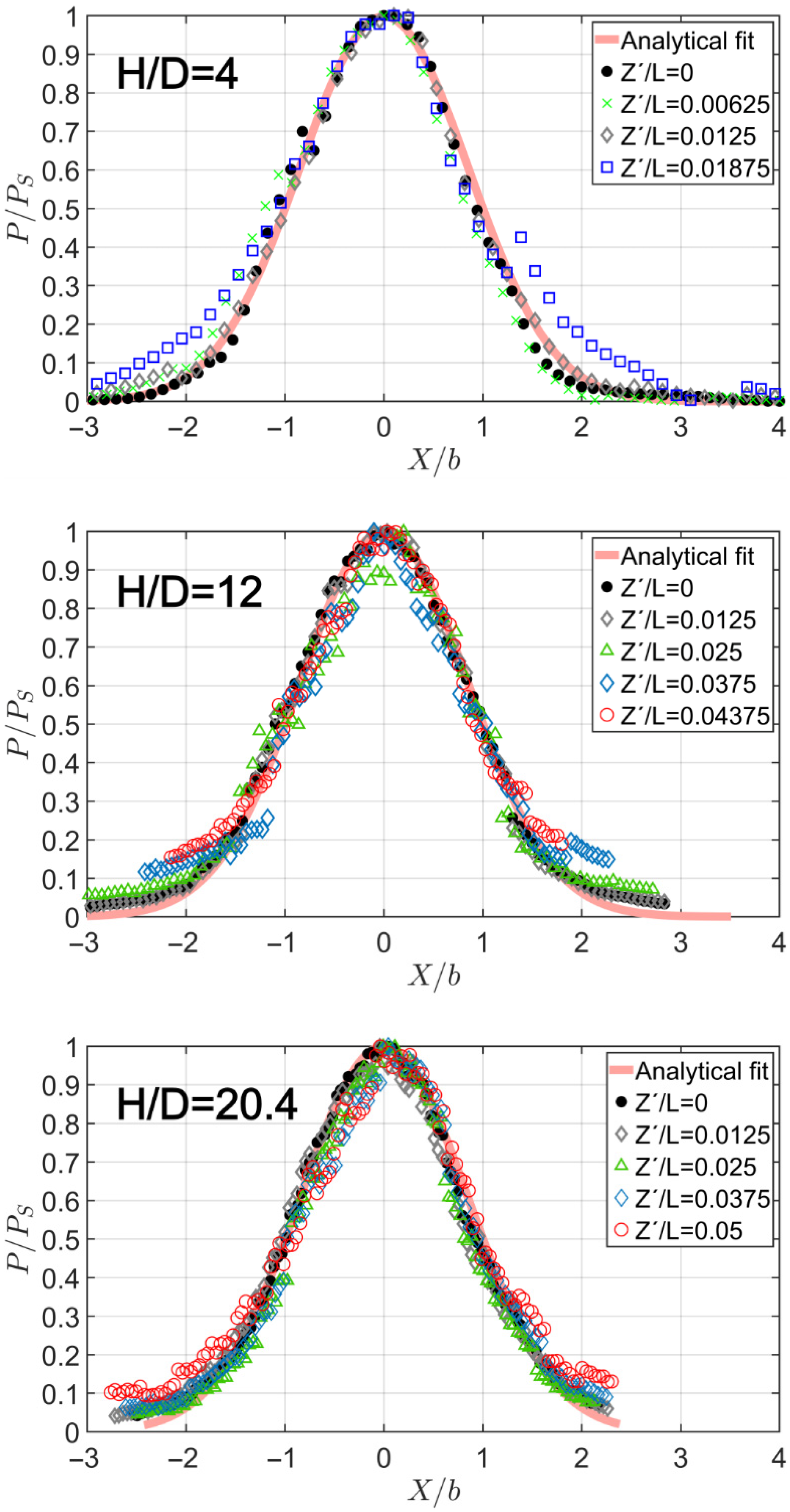
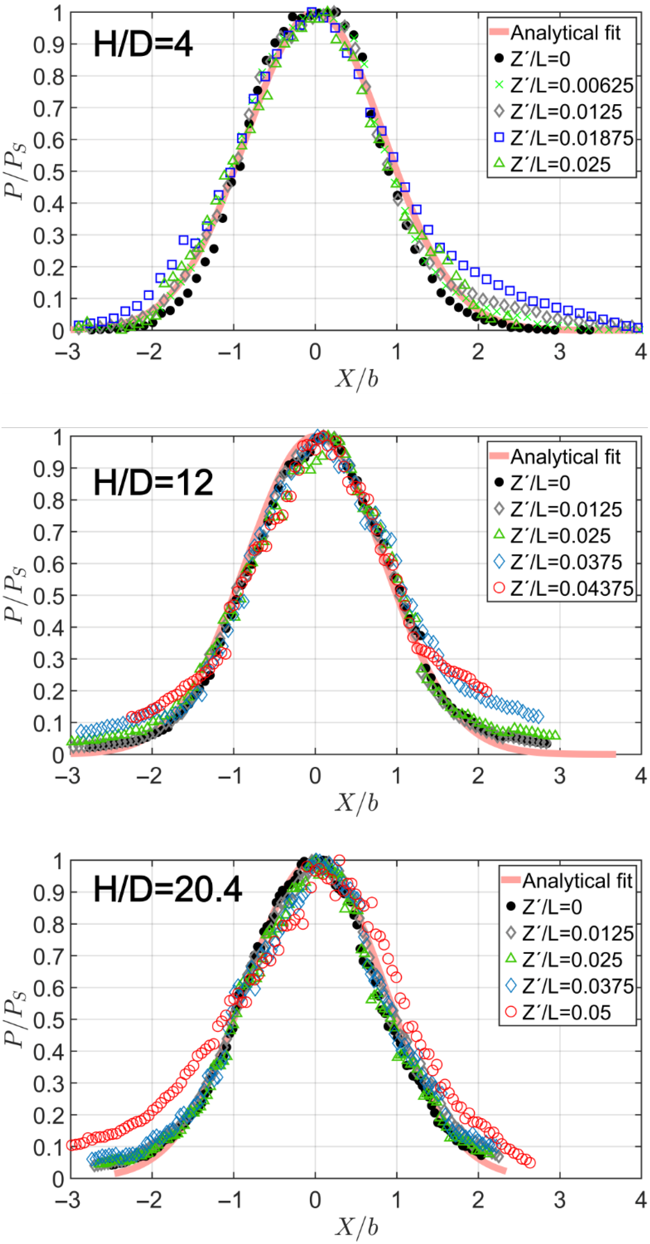
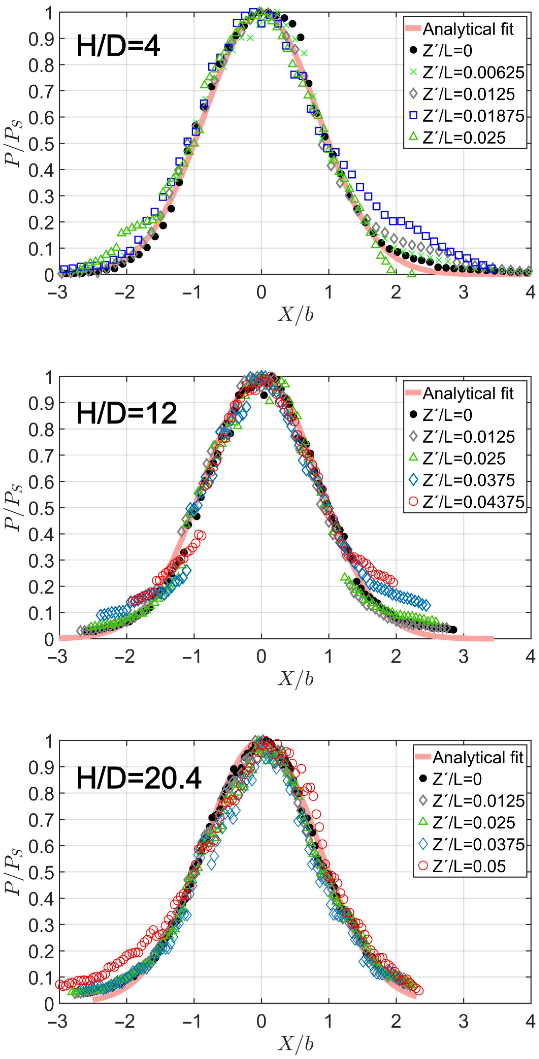
Figure 10,
Figure 11 and
Figure 12, the impingement pressure profiles for different
-coordinate positions in the tests with
for
are shown. The data were collected starting from 1 mm within the projection of the nozzle and moving outwards. Coordinate
can be seen in
Figure 7.
It should be noted that the results presented in
Figure 10,
Figure 11 and
Figure 12 correspond to the right side of the nozzle. Nevertheless, the authors would like to remark that the deviation between the left and right sides does not exceed
. To avoid redundancy, only the results from the right side are presented.
Note that in cases of
, since the nozzle is closer to the surface, the spreading of the jet in
direction is extended no more than 3 or 4 millimeters before the measured pressures are negligible. Thus, a lower number of pressure profiles are available in the top-of-figure subplots in
Figure 10,
Figure 11 and
Figure 12. On the other hand, more data series are available for larger
values, but certain series have been omitted for clarity.
From comparing
Figure 10,
Figure 11 and
Figure 12, it is confirmed that the whole set of pressure profiles presents an evident similarity. They follow a similar law to the one at the midspan (Equation (1), extracted from [
16]), only changing the maximum impingement pressure, which depends on the
-coordinate. Only minimal deviations were registered where the pressure approaches the uncertainty of the measurement process, which occurs at the largest
values and at the limit of the impingement region (large
). Comparing the experimental data with Equation (1), the agreement is excellent with
ranging from 0.9574 to 0.9865. The fact that the pressure profiles at the side boundaries match the same expression used for midspan is a finding not yet reported in the literature, to the authors’ knowledge.
On the other hand, the value of
for each profile measured at different
-coordinates also exhibits similarity.
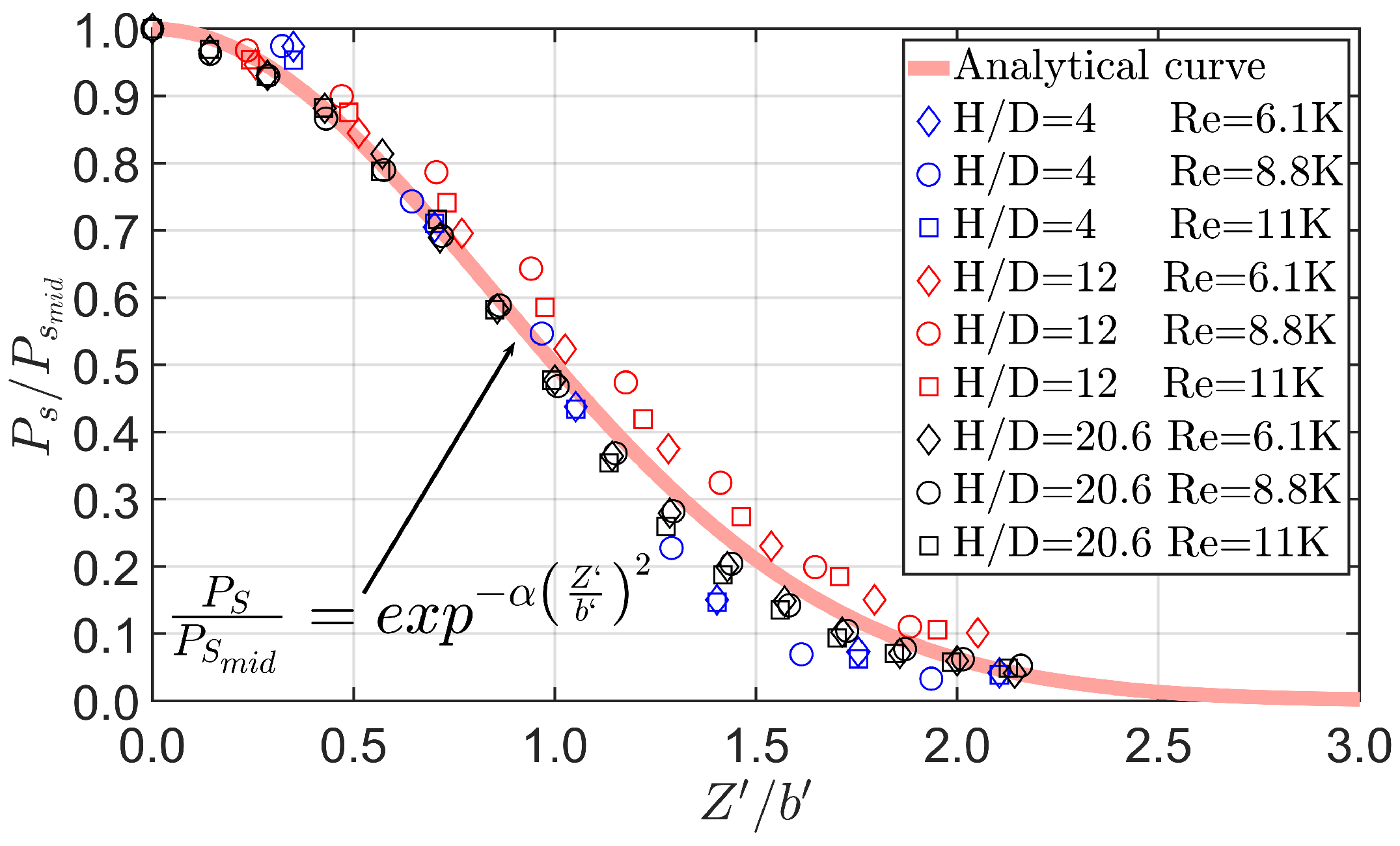
Figure 13 presents the dimensionless ratio between the maximum impingement pressure of each profile at the designated
-coordinate positions and the maximum pressure recorded at the midspan, which functions as the reference point. All the tests are included in this picture. Since this variable is closely related to the jet spreading, the data should match an expression of the same type as planar or round jets. Accordingly, the values adhere to a distinct trend that can be approximated by an expression of the form:
where
is measured as shown in
Figure 6, but in
-coordinate, from
up to the location of half-maximum pressure. The results agree very well with the proposed expression, reaching an excellent
when
. Thus, the pressure impingement profiles at the midspan in
-plane, the pressure profiles at the lateral boundaries of the air knife in
-planes for different
-coordinates, and the impingement pressure profile in the
-plane can be expressed using the same equation. This is surprising since it is known that rectangular free jets of large aspect ratios, see [
37,
38], register an almost negligible growth in the
-coordinate, in contrast to the transverse spreading, which increases almost linearly. This difference in the lateral spreading compared to other works, also observed in other research on rectangular free jets, is attributed to the nozzle geometry [
37,
38]. See those references for more information about the spreading phenomena.
Consequently, the impingement pressure profile can be characterized along the entire span of the air knife, including regions beyond the lateral boundaries, using mathematical formulations. Therefore, these findings assert that, once the exit velocity of the nozzle is evaluated, the mathematical expressions provided yield precise predictions of the pressure distribution of an air knife of finite length.
4. Conclusions
Experimental tests of an air knife blowing perpendicularly against a flat surface have been carried out in the present work. In addition to the conventional measurements of impingement pressure in the midplane, novel measurements were conducted to characterize the performance at the lateral sides of the impingement jet. This approach allowed us to evaluate the limitations associated with three-dimensional effects resulting from the finite length of the air knife. The test campaign covered different values of the ratio and the Re number to analyze a wide range of performance conditions.
Pressure profile measurements at midspan follow the well-known bell-shaped structure previously reported in the bibliography. On the other hand, the measurements at the sides of the impingement jet have unveiled interesting facts. Pressure profiles at these lateral regions show a clear similarity, which facilitates their analytical determination through mathematical expressions. The main finding of this work is that the impingement pressure profiles at the lateral boundaries of the jet agree extremely well with the same expression at the midspan.
Consequently, it becomes feasible to quantitatively characterize the pressure profiles within the impingement zone across the entire span of an air knife, encompassing areas influenced by the three-dimensional effects resulting from the finite length of the air knife. These findings highlight a characteristic that has not been previously documented in existing literature.
Nevertheless, the conclusions of this work should be extended beyond the specific geometry and operating conditions of the tested configuration with caution. Additional experiments covering a wider range of values, Reynolds numbers, and turbulence levels would provide further support for the conclusions drawn.




 ,
,