Abstract
Snow and ice accumulation on transportation infrastructure presents significant safety and maintenance challenges in cold regions, while conventional removal methods are both energy-intensive and environmentally detrimental. This study proposes a passive Heat Pipe–Coupled Geothermal Snow Melting System (HP-GSMS) that harnesses shallow geothermal energy to maintain snow-free surfaces without external energy input. Using Fluent-based CFD simulations, the system’s thermal performance was evaluated under various working fluids (ammonia, carbon dioxide, water) and pipe materials (stainless steel, aluminum). A one-dimensional thermal resistance model validated the CFD results under ammonia–stainless steel conditions, predicting a heat flux of 358.6 W/m2 compared to 361.0 W/m2 from the simulation, with a deviation of only 0.66%, confirming model accuracy. Ammonia demonstrated superior phase-change efficiency, with the aluminum–ammonia configuration yielding the highest heat flux (up to 677 W/m2), surpassing typical snow-melting thresholds. Aluminum pipes enhanced radial heat conduction without compromising phase stability, while water exhibited poor phase-change performance and CO2 showed moderate but stable behavior. Additionally, a dynamic three-node RC thermal network was employed to assess transient performance under realistic diurnal temperature variations, revealing surface heat fluxes ranging from 230 to 460 W/m2, with a daily average of approximately 340 W/m2. These findings demonstrate the HP-GSMS’s practical viability in cold climates and underscore the importance of selecting low-boiling-point fluids and high-conductivity materials for scalable, energy-efficient, and low-carbon snow-melting applications in urban infrastructure.
1. Introduction
Amid the escalating impacts of global climate change, extreme snow and ice events increasingly disrupt urban transportation, public infrastructure, and daily mobility in cold regions [1]. In the Waterloo region of Canada, for example, annual snowfall exceeds 200 cm, with extreme temperatures dropping below −30 °C. These harsh conditions render conventional snow removal methods inefficient, especially during heavy snowfall or extreme cold [2]. According to the Ontario Ministry of Transportation, winter road maintenance accounts for 38% of the annual transportation budget. Moreover, the widespread use of chemical deicers leads to severe environmental degradation, including corrosion of roads and bridges, with annual repair costs exceeding CAD 200 million. These practices also conflict with Canada’s 2050 net-zero emission targets [3,4]. This situation highlights the urgent need for more sustainable, energy-efficient, and environmentally friendly snow removal technologies.
Geothermal snow-melting technology has emerged as a promising solution due to its low energy demand, environmental compatibility, and high thermal efficiency [5]. It harnesses the stable heat of the subsurface isothermal layer, transferring geothermal energy to the surface through embedded heat exchange pipes to prevent snow and ice accumulation [6,7]. However, conventional U-shaped ground-coupled systems suffer from limitations. Continuous heat extraction disrupts subsurface thermal equilibrium, leading to thermal recovery periods of up to 6–8 months. Additionally, commonly used water-based fluids show significant performance degradation at low temperatures—exhibiting increased viscosity and over 40% reduction in thermal conductivity below −15 °C—compromising system efficiency in severe winter climates [8].
To address these limitations, this study proposes a novel Heat Pipe–Coupled Geothermal Snow Melting System (HP-GSMS). This system features a vertically extended evaporator penetrating the underground isothermal layer for heat extraction, and a horizontally embedded condenser within the pavement base for surface heating. This “deep heat extraction–shallow heat release” configuration enables unidirectional, efficient thermal transfer while maintaining subsurface thermal balance and enhancing long-term operational stability in cold environments.
Considering the region’s unique glacial till with low thermal conductivity and pronounced freeze–thaw cycles, this study integrates theoretical modeling and experimental validation. A multiphysics-coupled numerical model is developed, incorporating unsteady thermal conduction in pavement layers, porous soil flow, and the phase-change behavior of working fluids within the heat pipe. This study further evaluates the thermal performance of three working fluids—ammonia, carbon dioxide, and water—and compares two pipe materials—stainless steel and aluminum—under extreme cold conditions.
The proposed HP-GSMS system is expected to bring significant benefits to the Waterloo region. From an economic perspective, it will reduce the high maintenance costs associated with traditional snow removal methods, thereby easing public financial pressures [9,10,11]. Environmentally, using eco-friendly fluids like ammonia and CO2 eliminates the ecological damage caused by chloride-based deicers. From a resilience perspective, the system enhances roadway functionality and emergency responsiveness during extreme winter weather, contributing to a more sustainable and adaptive urban infrastructure.
2. Technical Principles and System Design
2.1. Principles of Heat Pipe Technology
The heat pipe is a highly efficient, passive thermal transfer device that operates via cyclic phase transitions (liquid ⇌ vapor) of a working fluid, driven by internal pressure gradients [12]. In the single-module simulation of the snow-melting system, a closed thermodynamic cycle is established. This section absorbs geothermal energy at a stable temperature of 10 °C [13], which causes the working fluid to vaporize. The generated vapor rises through the adiabatic section of the vertical heat pipe, which is insulated with a polyurethane foam layer. It then enters the horizontal heat pipe near the ground surface. This section functions as the condenser and is exposed to ambient air at 0 °C. Through natural convection, with a heat transfer coefficient of 50 W/m2·K [14,15], the vapor releases its latent heat and condenses. The resulting condensate returns to the evaporator under gravity along the pipe’s inner wall. A 5 m height differential in the vertical pipe and a 10° downward slope in the horizontal pipe ensure self-sustained fluid circulation without external power input. This configuration forms a continuous, passive geothermal-to-surface energy transfer system.
2.2. Selection of Heat Pipe Materials and Working Fluids
The selection of working fluid and pipe material critically influences the system’s thermal performance and reliability under low-temperature conditions. Ammonia (NH3), with a low boiling point (−33.3 °C) and high latent heat of vaporization (1370 kJ/kg), is ideal for cold climates. Carbon dioxide (CO2) offers environmental advantages and maintains a high saturation pressure at low temperatures (44.5 bar at 10 °C), enabling compact system design [16]. Water (H2O), although unsuitable for extremely cold conditions, provides exceptional latent heat (~2400 kJ/kg) for applications in moderate climates.
Pipe material selection balances thermal conductivity and mechanical performance. Stainless steel delivers superior structural integrity and pressure resistance, maintaining reliability under high thermal gradients and mechanical stress. In contrast, aluminum, with a much higher thermal conductivity (~237 W/m·K), significantly enhances heat transfer efficiency. Its lightweight nature also facilitates easier transport and installation, making it a practical choice for large-scale deployment.
2.3. System Configuration and Parametric Design (Single Module)
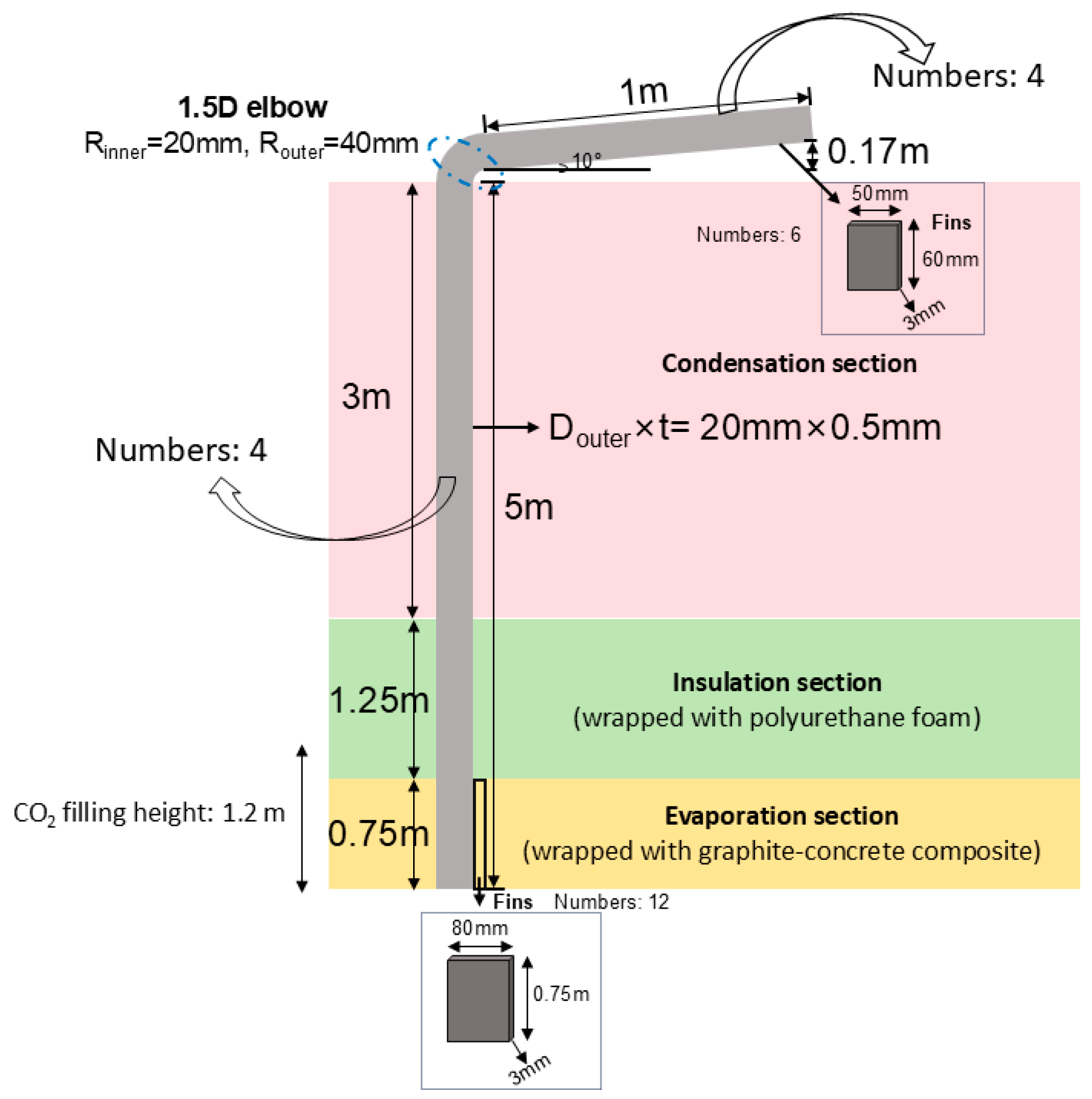
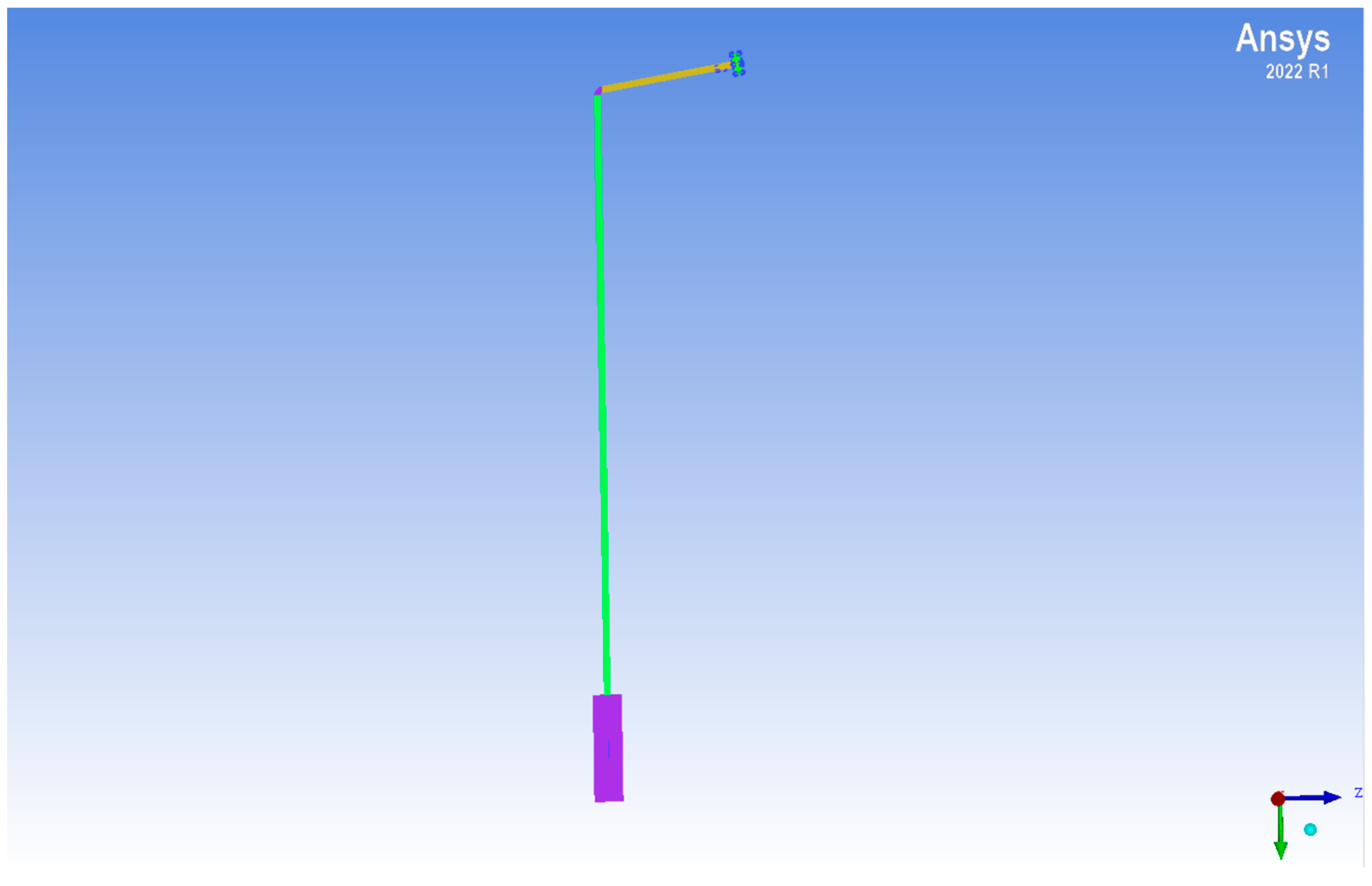
To evaluate the heat transfer performance of the geothermal-driven heat pipe system for snow melting, a single-module unit—comprising one vertical and one horizontal heat pipe—was developed. The structural layout and key geometric parameters are depicted in Figure 1, and the corresponding 3D numerical model is presented in Figure 2.
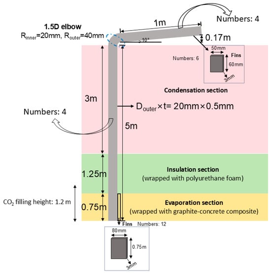
Figure 1.
Schematic diagram of the heat pipe module with key dimensions.
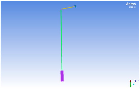
Figure 2.
3D model of the single-module heat pipe system (Ansys 2022 R1).
The system adopts a “vertical + horizontal” configuration to enable directional energy transfer from underground to the surface. The vertical heat pipe, with a total length of 5 m, is fully buried and consists of three segments: an evaporation section (0.75 m), an adiabatic section (1.25 m), and a condensation section (3 m), arranged from bottom to top. The evaporation section is embedded in a graphite–concrete composite to enhance geothermal heat absorption. To improve phase-change efficiency, 12 annular fins (80 mm height, 3 mm thickness, 0.75 m coverage) are installed along the evaporation zone.
The adiabatic section is insulated with polyurethane foam to minimize axial heat loss during vapor transport. In the condensation section, although still underground, heat is conductively transferred to the connected horizontal pipe. The vapor condenses in this region, releasing latent heat, and the condensate flows back to the evaporator along the pipe wall under gravity, forming a closed thermodynamic cycle. The vertical pipe has a uniform outer diameter of 20 mm and wall thickness of 0.5 mm, with a working fluid fill height of 1.2 m.
At the top, a 1.5D elbow (20 mm inner diameter, 40 mm outer diameter) connects the vertical pipe to a 1 m long horizontal pipe inclined upward at 10°, facilitating condensate return. To enhance heat dissipation in the surface-level condensation zone, six external fins (50 mm height, 60 mm coverage, 3 mm thickness) are mounted on the horizontal pipe. Additionally, a steel plate (1.5 m × 2.5 m × 5 mm) is embedded at the ground surface in direct contact with the horizontal pipe to simulate the snow-melting interface and promote latent heat release to the environment.
In the numerical model, the thermal contact resistance between the steel plate and the horizontal pipe is set to Rcontact ≈ 0.03 m2·K/W, representing realistic interfacial conditions. Local mesh refinement is applied to critical regions—such as the evaporation boundary layer (first-layer thickness: 0.05 mm), elbow transition, and fin surfaces—to resolve steep thermal gradients and phase-change dynamics with high accuracy. The full 3D model is constructed using ANSYS 2022 R1, as shown in Figure 2.
2.4. Mathematical Formulation
To accurately simulate the coupled heat transfer and phase-change behavior of the HP-GSMS, a set of governing equations is implemented within a CFD framework. These equations capture energy transport in solids, mass and momentum conservation in fluids, and latent heat effects during phase transitions [8,17]. All simulations are performed under steady-state conditions using the enthalpy–porosity model in ANSYS Fluent.
Heat conduction in solid domains—such as the pipe walls, steel plate, and surrounding soil—is governed by
where is the solid density, is the specific heat capacity, is the temperature, and is the thermal conductivity. Under steady-state conditions, the time derivative is neglected. This equation governs the spatial evolution of temperature through the system structure.
In the fluid domain, the continuity equation ensures mass conservation:
Here, represents the fluid density and is the velocity vector. This is especially critical in regions of phase change, where density varies locally due to vaporization or condensation.
Momentum transport is described by the incompressible Navier–Stokes equation:
where is the pressure, is the dynamic viscosity, and is the gravitational acceleration vector. This equation captures fluid motion driven by pressure gradients and buoyancy, enabling accurate modeling of vapor transport from evaporator to condenser.
The thermal energy equation accounts for both sensible and latent heat effects and is expressed as
The specific enthalpy in this context includes contributions from both temperature change and phase change, defined as
where is the specific heat capacity at constant pressure, is the latent heat of vaporization, and is the local liquid fraction. This approach allows for smooth tracking of phase transitions without explicit interface resolution, improving numerical stability.
The evolution of the liquid fraction is determined using a piecewise linear interpolation based on temperature:
This formulation enables a smooth transition between solid and liquid phases across a narrow temperature interval, avoiding numerical oscillations near the phase boundary.
Collectively, these equations form a comprehensive model for simulating the thermo-hydraulic behavior of the HP-GSMS. Temperature-dependent physical properties—including density, thermal conductivity, specific heat, and viscosity—are assigned to accurately represent the behavior of ammonia, carbon dioxide, and water as working fluids. Boundary conditions include a geothermal heat flux at the base, adiabatic constraints along insulated sections, and convective cooling at the top surface. This robust mathematical foundation supports reliable numerical analysis and performance evaluation of the proposed system.
3. Numerical Simulation and Methodology
3.1. Fluent Simulation Setup
To evaluate the thermal performance of the HP-GSMS under different working fluids and pipe materials, a multiphysics-coupled CFD model was developed using ANSYS Fluent 2022 R1. The model incorporates solid conduction, phase-change heat transfer, and porous soil behavior. The geometry is based on the single-module configuration described in Section 2.3, consisting of one vertical and one horizontal heat pipe embedded in soil and connected to a ground-level steel plate. A structured hexahedral mesh was employed, with local refinement applied to critical regions such as phase-change zones, fins, elbows, and thermal contact interfaces. Boundary conditions were defined as follows: a geothermal heat source at 10 °C was applied at the base of the vertical pipe, while the steel plate near the horizontal condenser was maintained at 2 °C. Natural convection was imposed on external surfaces with a heat transfer coefficient of 50 W/m2·K. Working fluids—ammonia, carbon dioxide, and water—were modeled with temperature-dependent thermophysical properties using the enthalpy–porosity method to capture phase-change phenomena. Pipe walls were assigned thermal conductivities of 16.2 W/m·K for stainless steel and 237 W/m·K for aluminum, with consistent wall thicknesses maintained across materials for comparative analysis.
To ensure the numerical robustness of the CFD simulations, the convergence behavior of all governing equations—including continuity, momentum, and energy—was closely monitored. In all simulation cases, the residuals of these equations were reduced below 1 × 10⁻⁶ within 2000 iterations, demonstrating strong numerical convergence. To avoid pseudo-convergence, key physical variables such as the average surface heat flux on the condenser plate and the vapor–liquid fraction distribution within the heat pipe were also tracked. These variables exhibited stabilization within the final 500 iterations, with fluctuations remaining below 1%, indicating consistent thermodynamic behavior and convergence at the physical level. A mesh independence analysis was performed using three different mesh densities: coarse (approximately 0.48 million cells), medium (approximately 0.76 million cells), and fine (approximately 1.12 million cells), based on the ammonia–stainless steel configuration. The predicted surface heat flux differed by less than 2.1% across these cases, and the thermal distributions obtained from the medium and fine meshes were nearly identical. These results confirm that the simulations are independent of mesh resolution. Accordingly, the medium-resolution mesh was selected for all reported cases to achieve a balance between computational cost and accuracy.
3.2. Comparative Simulation of Working Fluids and Pipe Materials
To evaluate the impact of working fluid selection on system performance, three simulation scenarios were conducted using stainless steel pipes with ammonia (NH3), carbon dioxide (CO2), and water (H2O) as working fluids. All cases shared identical geometries and boundary conditions. Key performance metrics included total surface heat flux and vapor–liquid volume fraction, which jointly characterize heat transfer efficiency and phase-change behavior. The fluid yielding the highest total heat flux at the condenser surface was identified as the optimal working fluid. Subsequently, a fourth simulation was conducted using this optimal fluid in combination with an aluminum pipe to isolate and assess the effect of pipe material. All simulations were run to convergence, with residuals below 10−6, and identical post-processing procedures were applied to ensure consistency and comparability across all cases.
3.3. Analysis Methodology
Two primary indicators were used to evaluate system performance: total surface heat flux and vapor–liquid volume fraction. Surface heat flux was computed on the horizontal pipe and steel plate to quantify thermal output and assess snow-melting capacity. The vapor–liquid volume fraction was evaluated throughout the entire heat pipe domain to reflect phase-change efficiency and the steady-state behavior of the working fluid. Together, these metrics provide a comprehensive understanding of both external energy transfer and internal thermodynamic processes within the system [18,19]. Consistent post-processing methodologies were applied to all simulations to ensure reliable comparisons across different working fluids and pipe materials.
4. Results and Discussion
4.1. Model Validation
To verify the accuracy of the Fluent numerical simulation results and enhance the credibility of this study’s findings, a simplified one-dimensional thermal resistance network (1D Thermal Resistance Network, TRN) was established to calculate the steady-state surface heat flux and perform cross-validation with the CFD simulation outputs. This validation specifically compares the simplified model with the CFD results for the case using ammonia as the working fluid and stainless steel pipes.
In this framework, the heat transfer path includes the following:
- From the underground isothermal layer (Tgeo = 10 °C) to the outer wall of the evaporation section;
- Radial conduction through the heat pipe wall;
- Thermal contact resistance between the pipe and the ground steel plate;
- Natural convective heat transfer between the ground steel plate and the ambient air.
The steady-state heat flux is calculated using
where the temperature difference ΔT represents the difference between the underground temperature and the surface temperature, taken as 8 K (Tgeo = 10 °C, Tsurf = 2 °C).
The total thermal resistance is expressed as
Soil thermal resistance Rsoil:
Evaluated as the ratio of the effective heat transfer distance in the soil layer to its thermal conductivity,
Pipe radial conduction resistance Rpipe:
where kpipe accounts for the enhanced effective thermal conductivity due to phase change and internal vapor–liquid convective heat transfer during operation.
Thermal contact resistance Rinterface:
Represents the thermal resistance at the contact interface between the pipe and the steel plate.
Surface convective heat transfer resistance Rsurface:
Determined by the natural convective heat transfer coefficient and effective surface area,
These components together define the total thermal resistance of the system, which can be used to estimate the steady-state surface heat flux under specified thermal boundary conditions using
where ΔT is the temperature difference between the geothermal source and the surface environment.
By summing these values, the total thermal resistance of the system is calculated as Rtotal = 0.022641 m2·K/W. Under a temperature difference of 8 K, the predicted steady-state heat flux is q = 353.34 W/m2. This result is in excellent agreement with the Fluent simulation value of 361 W/m2, with a relative deviation of only 2.12%.
The excellent agreement confirms that the 1D TRN model effectively captures the dominant heat transfer mechanisms and provides a reliable approximation of overall thermal performance under steady-state conditions. This validation supports the credibility of the CFD approach and reinforces the HP-GSMS’s potential for stable and efficient operation in low-temperature environments. Detailed parameters and calculation procedures are provided in Appendix A. It should be noted that while the one-dimensional thermal resistance network provides strong agreement with the steady-state CFD results, this method inherently simplifies complex transient behaviors within the heat pipe, including vapor–liquid interface fluctuations, condensate retention, and capillary transport dynamics. These factors are critical under non-steady or spatially varying conditions. Therefore, while useful for baseline validation, the TRN framework does not replace high-resolution multiphysics models. Future work will consider transient CFD simulations with enhanced phase-change tracking to address these dynamic phenomena.
4.2. Comparison of Working Fluids: Ammonia, Carbon Dioxide, and Water
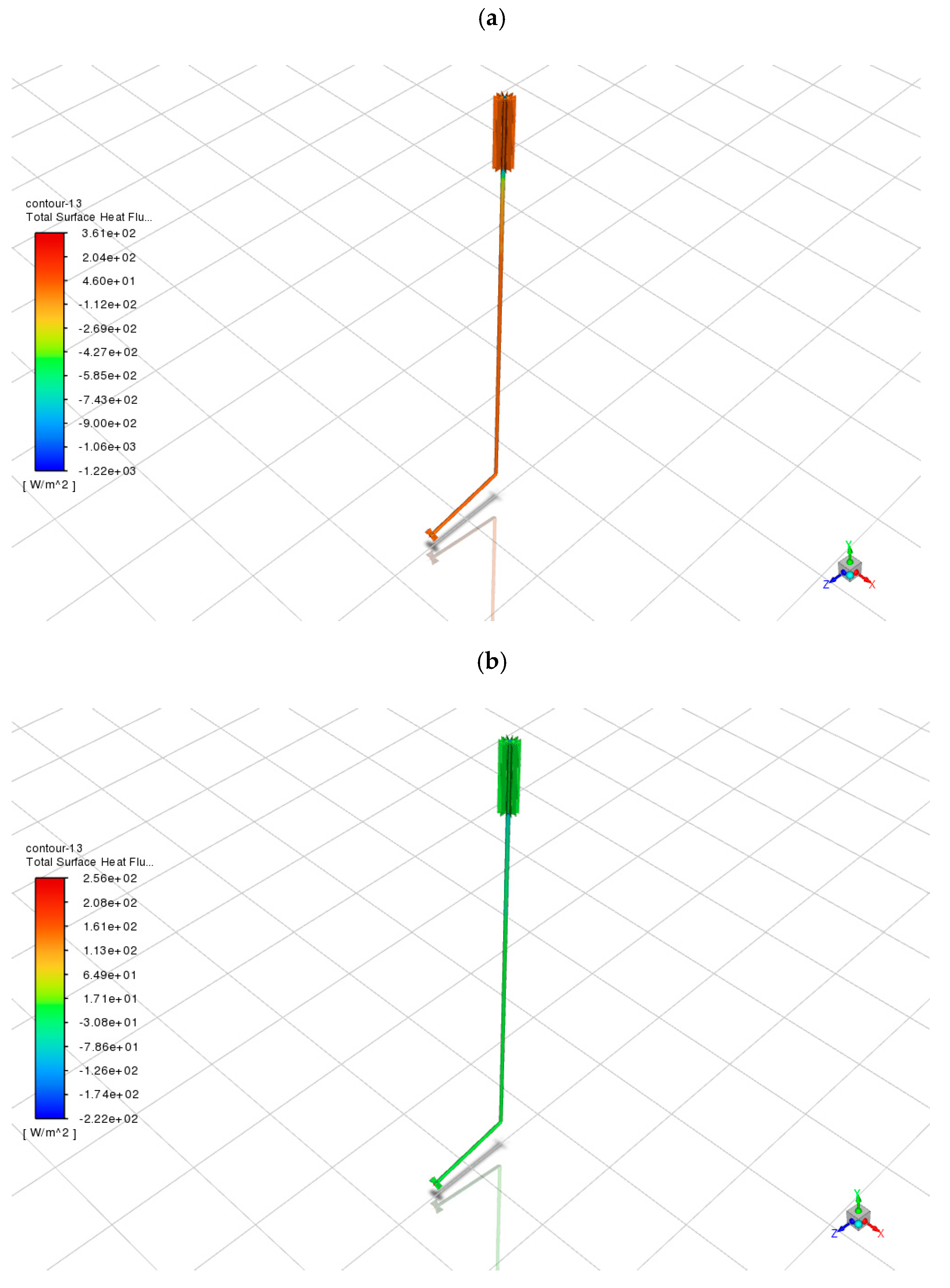
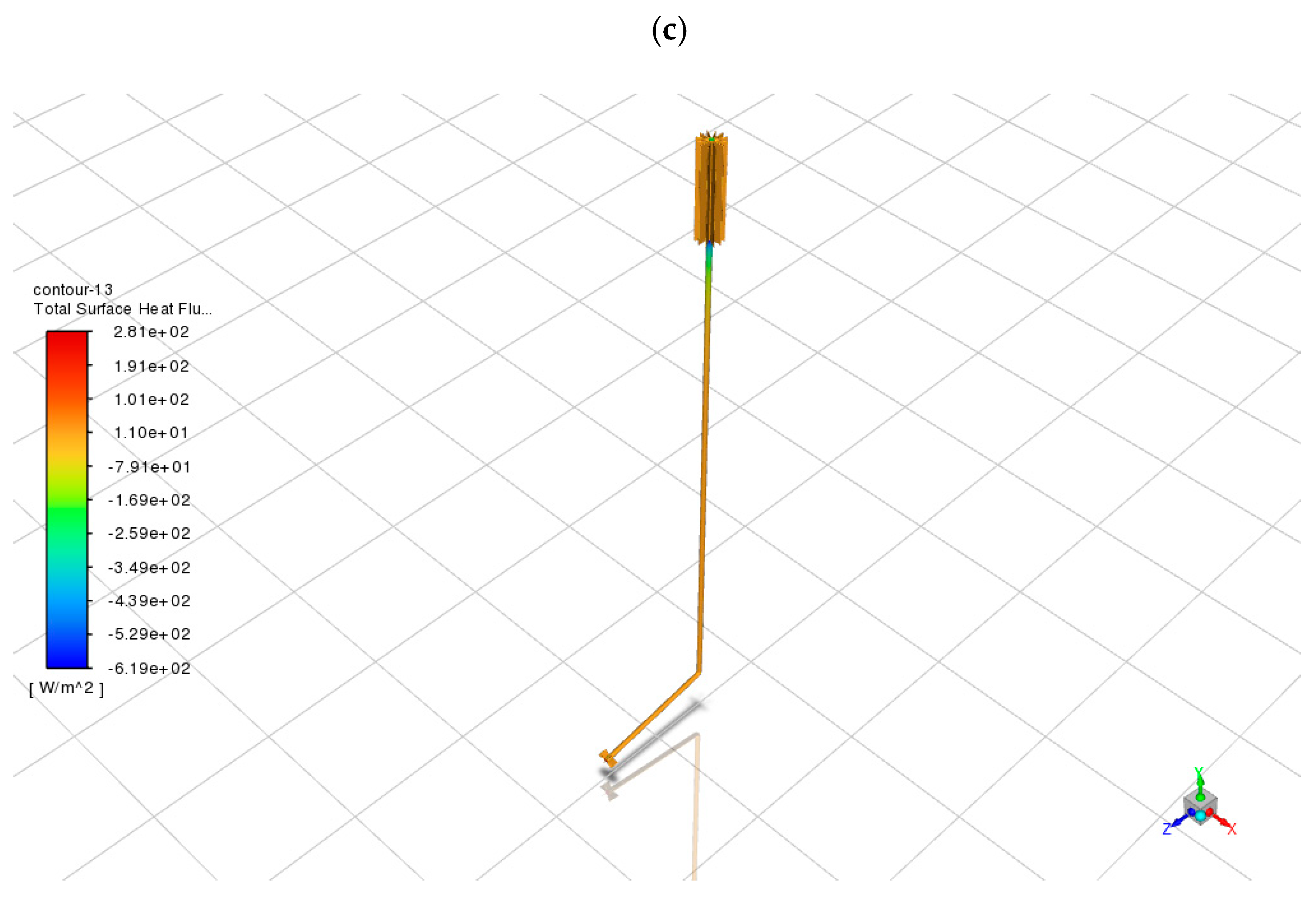
To assess the impact of working fluid selection on the thermal performance of the HP-GSMS, three simulation scenarios were conducted under identical geometric and thermal boundary conditions using stainless steel pipes. The resulting surface heat flux distributions for ammonia (NH3), carbon dioxide (CO2), and water (H2O) are shown in Figure 3a–c.
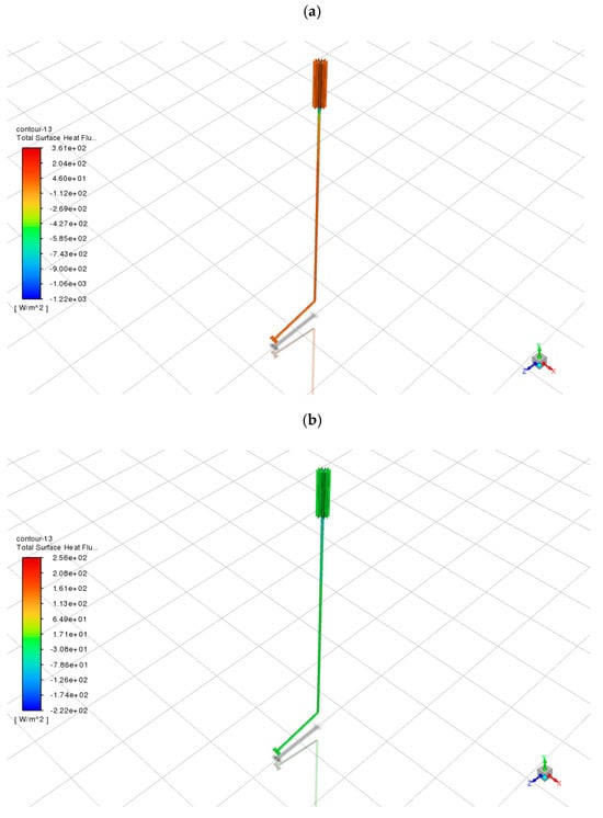
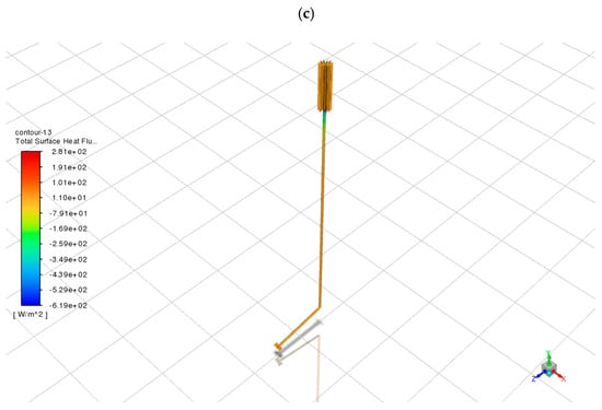
Figure 3.
Total surface heat flux distributions for different working fluids in stainless steel pipes: (a) NH3; (b) CO2; (c) H2O.
Among the tested fluids, ammonia exhibited the best performance. As shown in Figure 3a, the peak surface heat flux reached approximately 361.6 W/m2, with high flux density concentrated in the horizontal condenser and upper finned regions of the vertical pipe. More importantly, the spatial distribution was uniform, with most areas exceeding 250 W/m2 and no evidence of thermal stagnation or backflow. This reflects effective vapor transport and latent heat release during condensation [20]. Ammonia’s low boiling point (−33.3 °C), high latent heat of vaporization (1370 kJ/kg), and moderate saturation pressure facilitate stable phase change even under low geothermal input (10 °C). These results confirm that ammonia can sustain surface heat flux levels above typical snow-melting thresholds (200–300 W/m2), making it well-suited for sidewalks, roads, and public spaces in cold climates [21].
In contrast, CO2 exhibited lower and more heterogeneous heat flux patterns. Figure 3b shows a maximum heat flux of 256.0 W/m2, barely meeting the minimum requirement for snow melting. Substantial portions of the surface, especially near the elbow and lower horizontal regions, showed flux values below 100 W/m2, suggesting inefficient heat release due to premature condensation or limited vapor flow. While CO2 is environmentally friendly and readily available, its high operating pressure (44.5 bar at 10 °C) and lower latent heat (574 kJ/kg) reduce its effectiveness in passive systems [22].
Water, as shown in Figure 3c, yielded a peak heat flux of 281.0 W/m2, slightly higher than CO2. However, its distribution was poor, with most regions below 150 W/m2 and areas of negative flux, indicating possible reverse conduction or thermal stagnation. Due to its high boiling point (100 °C) and low vapor pressure at 10 °C, water exhibits limited phase change under these conditions. Despite its high latent heat (2400 kJ/kg), the system fails to activate sufficient evaporation, making water unsuitable for low-temperature snow melting without external heating or pressure augmentation [6,23].
Overall, ammonia provided the highest and most consistent heat flux output under passive operation. Its distribution suggests efficient and uniform thermal delivery across the target surface. CO2 may be feasible in pressure-assisted systems, while water is not recommended for passive snow-melting applications without system enhancements.
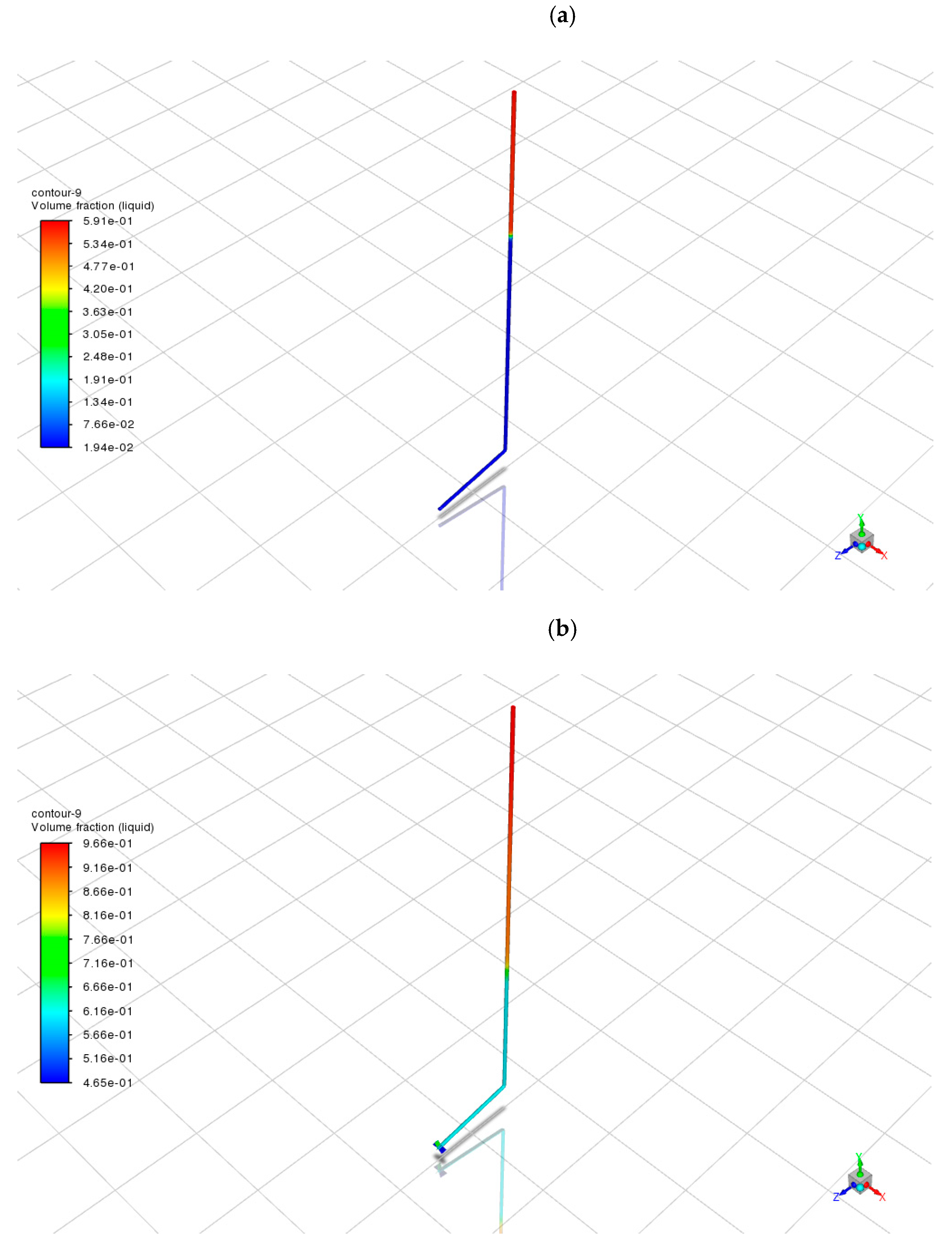
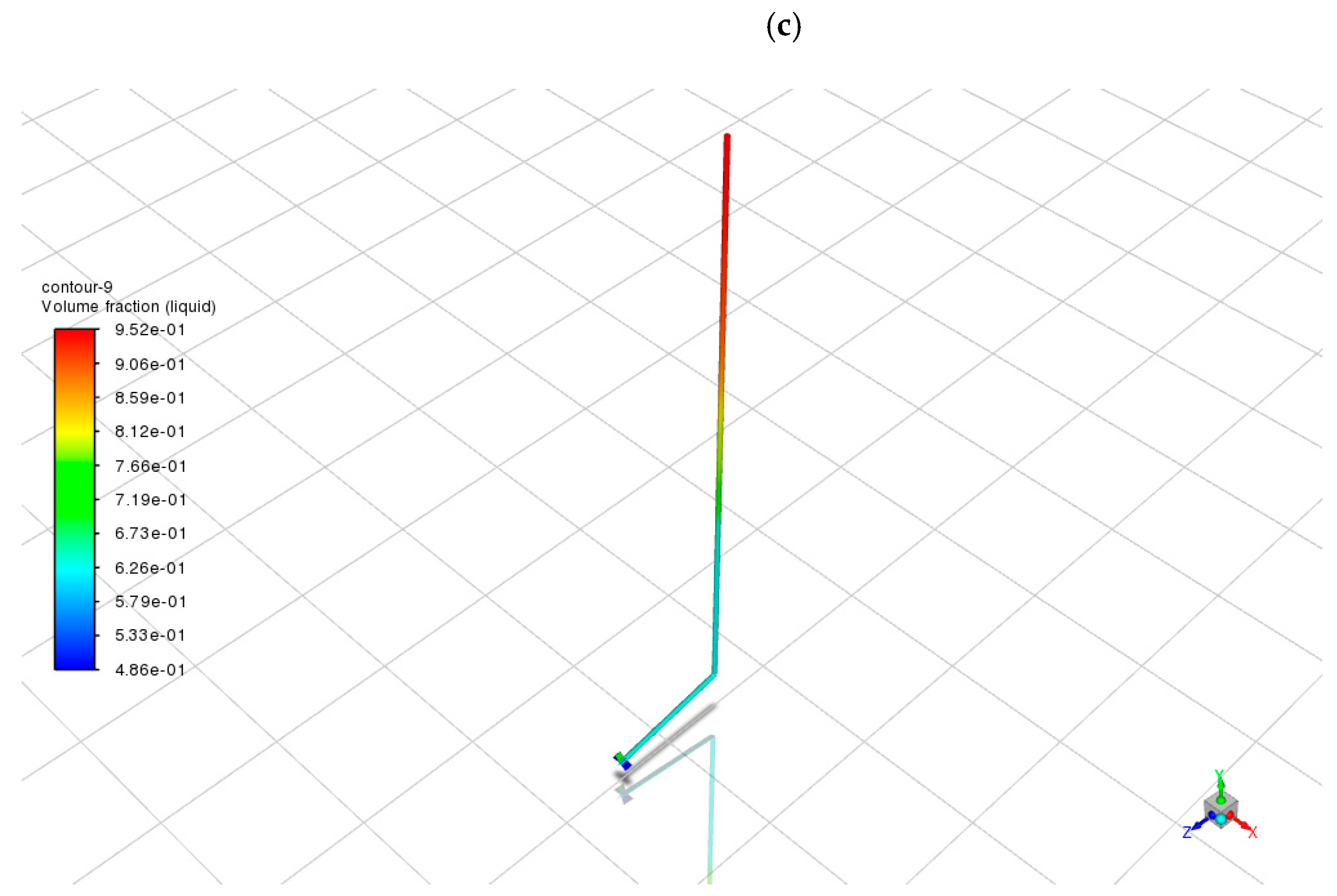
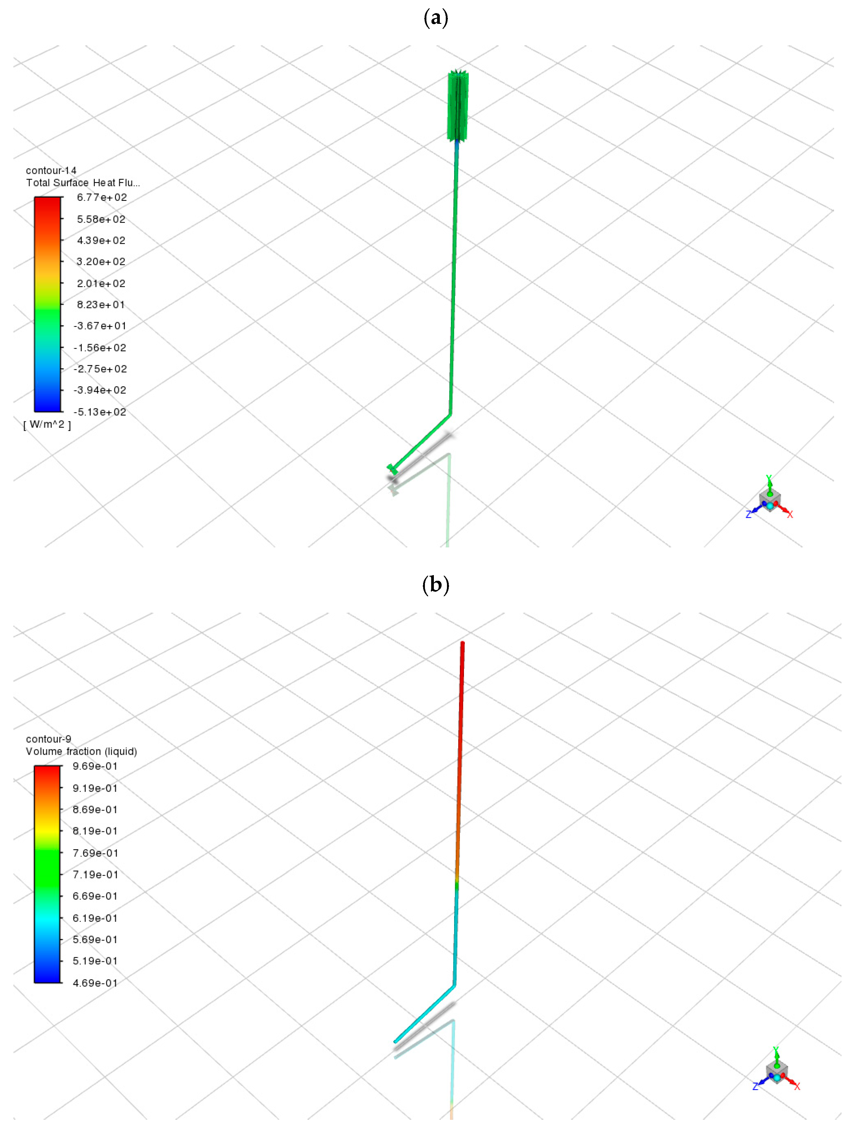
Beyond surface heat flux, the vapor–liquid volume fraction distribution provides critical insight into internal phase-change dynamics, fluid circulation, and thermal conversion stability. Figure 4a–c illustrates the liquid-phase distributions for NH3, CO2, and H2O, respectively.
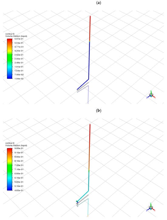
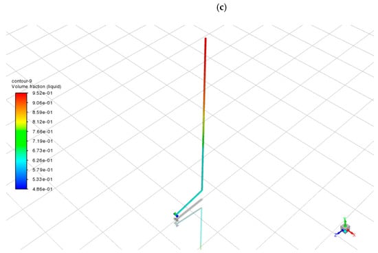
Figure 4.
Volume fraction (liquid phase) distributions for different working fluids in stainless steel pipes: (a) NH3; (b) CO2; (c) H2O.
As shown in Figure 4a, ammonia presents a distinct stratified liquid distribution. The condenser region near the top accumulates a high liquid volume fraction (up to 0.59), while the evaporator and adiabatic sections maintain low values (<0.20), indicating efficient vapor generation and condensation. The sharp gradient along the pipe and absence of flooding confirm a stable, self-sustained phase-change cycle. Smooth liquid return under gravity further supports continuous passive operation [24].
In contrast, the CO2-filled case (Figure 4b) shows a noticeably different distribution. The entire vertical pipe contains a relatively high liquid volume fraction, with values ranging from 0.45 to 0.97 throughout, suggesting the presence of condensed fluid along much of the pipe length. Although the top of the pipe still accumulates the most condensed phase (as expected), the absence of a clear liquid–vapor interface and the extensive presence of liquid in the mid and lower sections imply poor vapor transport efficiency and incomplete evaporation. This is likely a result of CO2’s high saturation pressure at 10 °C (~44.5 bar), which makes full vaporization more difficult under limited energy input, especially in a passive system [25]. The relatively large volume of liquid throughout the pipe may hinder heat transfer, reduce flow velocity, and increase thermal resistance, ultimately lowering overall system performance despite a high local condensation rate.
Water (Figure 4c) shows intermediate behavior. While the condenser exhibits a high liquid fraction (up to 0.95), the rest of the pipe also retains substantial liquid (minimum > 0.48). This indicates weak evaporation in the lower section and limited vapor migration. Water’s high boiling point and low volatility at 10 °C hinder effective phase cycling despite its large latent heat capacity [26,27].
Comparatively, ammonia shows the most favorable vapor–liquid separation, supporting robust phase change and directional heat transport. CO2 suffers from over-condensation and incomplete vapor flow, while water’s limited evaporation results in a liquid-dominant system, incapable of sustaining efficient cycling without external input.
When considered alongside surface heat flux results (Figure 3), the vapor–liquid profiles in Figure 4 strongly support ammonia as the optimal working fluid under passive geothermal snow-melting conditions. Its effective phase separation, efficient condensation, and stable return path enable consistent performance in subzero environments. Our simulation findings are in general agreement with previous experimental observations of snow-melting performance using ammonia-based or CO2-assisted geothermal systems [28,29].
4.3. Comparison of Pipe Materials: Stainless Steel vs. Aluminum
To further investigate the impact of pipe material on system performance, a fourth simulation was performed using NH3 as the working fluid and aluminum as the pipe material, replacing stainless steel. This material comparison was confined to ammonia because it exhibited the highest phase-change efficiency in preceding evaluations. Given the poor evaporation characteristics of water and the pressure sensitivity of CO2 under passive operating conditions, ammonia was deemed the most representative and thermodynamically viable scenario for isolating material effects. The corresponding results are presented in Figure 5a,b, including the total surface heat flux distribution and the vapor–liquid volume fraction map. Future investigations will aim to extend this comparison to encompass all fluid–material pairings, enabling a more comprehensive factorial assessment.
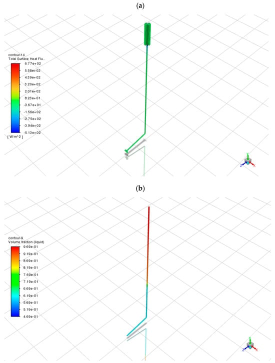
Figure 5.
Simulation results for ammonia in aluminum pipes: (a) Total surface heat flux distribution; (b) vapor–liquid volume fraction distribution.
As shown in Figure 5a, the aluminum pipe system achieves a peak surface heat flux of approximately 677.0 W/m2—an increase of nearly 40% compared to its stainless steel counterpart (361.6 W/m2 in Figure 3a). This significant enhancement is attributed to aluminum’s high thermal conductivity (237 W/m·K), which is over 14 times greater than that of stainless steel (16.2 W/m·K). The superior conductivity enables more efficient radial heat transfer from the fluid core to the pipe exterior.
Importantly, this enhancement is not localized; a substantial portion of the horizontal condenser section consistently maintains heat fluxes above 400 W/m2—well above the typical snow-melting threshold of 200–300 W/m2. The higher flux intensity suggests that aluminum facilitates faster and more uniform heat release, making it particularly suitable for applications requiring broad and consistent deicing coverage.
The heat flux distribution along the vertical pipe also exhibits a more gradual gradient compared to the stainless steel case, indicating that aluminum not only enhances local conduction at the condenser but also promotes axial heat transport. This minimizes thermal losses within the pipe and maximizes energy delivery to the surface [30].
The corresponding vapor–liquid volume fraction map (Figure 5b) supports these observations. The condenser region shows a high liquid volume fraction (>0.96), confirming efficient condensation. The evaporator remains predominantly vapor-filled (liquid fraction <0.30), indicating a stable and continuous phase-change cycle. Compared to the stainless steel configuration, the aluminum system demonstrates a smoother vapor–liquid transition and more uniform distribution, suggesting improved circulation dynamics and condensate return—likely facilitated by reduced thermal resistance and enhanced wall-to-fluid heat exchange [31,32].
Among all tested materials—including aluminum, stainless steel, and hypothetical low-conductivity alternatives such as plastic or uncoated carbon steel—aluminum offers the greatest potential for thermal enhancement in passive snow-melting systems. While stainless steel excels in mechanical strength, corrosion resistance, and pressure tolerance, its low thermal conductivity limits its effectiveness in heat transfer-driven applications. In contrast, aluminum strikes a balance between thermal performance and structural adequacy for moderate service conditions, making it an attractive candidate for retrofitting cold-climate infrastructure.
Nonetheless, practical deployment must consider cost, susceptibility to oxidation, and fatigue under thermal cycling. In some scenarios, hybrid solutions—such as composite pipes with aluminum liners or thermally coated stainless steel—may provide an optimal compromise between durability and performance.
To support a more systematic material selection strategy, future work will incorporate multi-criteria decision-making tools such as the Analytic Hierarchy Process (AHP). This approach allows different performance metrics—including thermal efficiency, cost, corrosion resistance, fatigue strength, and environmental adaptability—to be quantitatively compared and weighted. An example AHP matrix has been constructed to reflect typical engineering priorities, as detailed in Appendix C. This method enables a balanced evaluation of pipe materials beyond simulation metrics alone, aiding more informed design decisions for real-world applications.
4.4. System Performance Evaluation
A comprehensive evaluation of the HP-GSMS was conducted by integrating results from surface heat flux distributions, vapor–liquid volume fractions, and material-specific thermal behavior. This analysis provides a holistic understanding of how working fluid type and pipe material jointly influence snow-melting performance, phase-change stability, and practical applicability in cold climates.
Among all tested configurations, the ammonia–aluminum system exhibited superior performance across all thermal indicators. It achieved the highest peak surface heat flux (677.0 W/m2) and demonstrated a well-defined, efficient phase-change cycle—characterized by high liquid fractions (>0.96) in the condenser and a vapor-dominant evaporator. Aluminum’s high thermal conductivity significantly improved radial heat transfer, enabling rapid and uniform energy delivery to the surface. The recorded heat flux values not only exceed the empirical snow-melting threshold (typically 200–300 W/m2) [33,34] but also suggest a margin of safety for system performance under variable weather conditions.
The stainless steel–ammonia configuration, while slightly less efficient, still performed reliably, with a peak flux of 361.6 W/m2. It maintained stable phase separation and circulation, with minimal thermal loss along the vertical shaft. Although stainless steel’s lower thermal conductivity limits rapid responsiveness, its thermal inertia may contribute to system stability during freeze–thaw cycles and intermittent snowfall.
The CO2–steel system yielded moderate results. Despite CO2’s environmental friendliness and structural safety under high pressure, its relatively low latent heat (574 kJ/kg) and high saturation pressure at 10 °C (44.5 bar) limited vapor generation. This resulted in a flatter heat flux profile (peak: 256.0 W/m2) and widespread liquid accumulation, impeding effective phase cycling. The absence of a distinct vapor–liquid interface indicates inefficient circulation. Nonetheless, with pressure-assisted enhancements, CO2 remains a viable option, especially for compact or eco-friendly system designs.
The water–steel system, though theoretically advantageous due to its high latent heat (2400 kJ/kg), showed the poorest performance in practice. Its high boiling point and low volatility at 10 °C severely restricted phase change, leading to a predominantly liquid-filled pipe, weak vapor transport, and a maximum surface heat flux of only 281.0 W/m2. Regions of negative flux further indicated local heat absorption rather than release, undermining the snow-melting function. Without external heating or pressurization, water is unsuitable for low-energy passive systems in freezing conditions.
From a reliability standpoint, the ammonia–aluminum configuration demonstrated the most stable and self-sustaining operation. The effective gravitational return, minimal flooding, and absence of vapor choke ensure robust, long-term performance without mechanical intervention—an essential feature for infrastructure applications with limited maintenance access.
From an engineering integration perspective, pipe material selection must balance thermal performance, mechanical strength, and lifecycle cost. While aluminum offers superior heat transfer, it is more prone to oxidation and thermal fatigue. Stainless steel, despite its lower conductivity, provides excellent durability. A promising design strategy could involve hybrid structures—such as aluminum-lined steel pipes or polymer-coated aluminum—to combine the advantages of both materials.
To facilitate cross-case comparison, Table 1 summarizes the key performance metrics across all simulation scenarios, including surface heat flux extremes, vapor–liquid distribution, and qualitative assessments of phase-change stability. This consolidated view supports clearer interpretation of system-level trade-offs discussed in subsequent sections.

Table 1.
Summary of key performance indicators under different working fluids and pipe materials.
4.5. Dynamic Performance Analysis
To evaluate the dynamic heat transfer behavior of the geothermal snow-melting system under typical winter diurnal temperature cycles, a three-node dynamic RC (thermal resistance–capacitance) network model was developed. The model includes the soil layer, steel plate, and snow layer, and is configured based on real-world conditions using ammonia as the working fluid and 304 stainless steel as the pipe material.
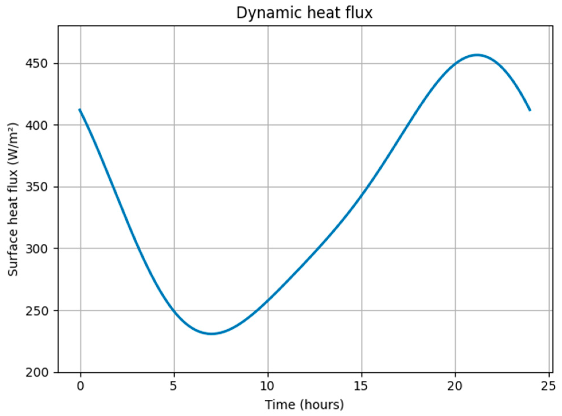
The simulation incorporates sinusoidal ambient temperature variations (from −20 °C to −5 °C), time-dependent convective heat transfer coefficients reflecting wind speed fluctuations (10–15 W/m2·K), and accounts for snow layer thermal resistance and latent heat consumption during melting. Using energy conservation principles, the model sequentially calculates temperature evolution and heat flux across system components, including the soil, composite shell, steel plate, and snow layer. By incorporating the thermal conductivity of snow, natural surface convection, and ammonia’s latent heat of vaporization, the model captures the temporal variation in surface heat flux throughout a 24 h cycle. Detailed parameter settings and the simulation implementation, conducted using Python 3.12, are provided in the Python code in Appendix B. As shown in Figure 6, the system’s surface heat flux exhibits clear diurnal oscillations, with nighttime minima around 230 W/m2 and daytime peaks near 460 W/m2, resulting in an average flux of approximately 340 W/m2. Notably, the nighttime troughs and most daytime periods maintain heat flux levels above the typical snow-melting threshold (200–300 W/m2), while showing good agreement with the CFD steady-state simulation results (361 W/m2). This indicates that the system possesses robust dynamic snow-melting capability under idealized diurnal fluctuations. It should be noted that the ambient temperature profile was modeled as a smooth sinusoidal variation for clarity and control in baseline evaluation. In reality, stochastic fluctuations may exist due to meteorological variability. Future studies will incorporate measured or noise-augmented temperature data to assess the system’s resilience under more realistic and uncertain boundary conditions. This seemingly counterintuitive phenomenon—lower surface heat flux during nighttime despite a higher ground-to-air temperature difference—can be explained by the thermal inertia of the system and surface resistance effects. Specifically, the steel plate and snow layer act as thermal capacitors, delaying heat transfer despite the large driving temperature gradient. Additionally, the snow layer’s low thermal conductivity and reduced convective heat transfer coefficients at night (due to lower wind speeds) further suppress instantaneous heat flux, resulting in the observed minimum during nighttime hours.
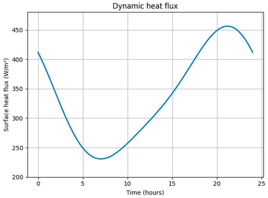
Figure 6.
Dynamic surface heat flux of the geothermal snow-melting system over 24 h under typical winter diurnal conditions.
5. System Optimization and Scalability
5.1. Design Optimization Strategies
Based on the simulation results, several key parameters have been identified to enhance system performance. First, the choice of working fluid is critical. Ammonia consistently outperformed other fluids due to its low boiling point, high latent heat of vaporization, and favorable vapor–liquid distribution under low-temperature geothermal input. Future designs should prioritize low-boiling-point fluids with stable thermodynamic properties in subzero environments [35]. Environmentally benign alternatives—such as ammonia derivatives or ammonia–CO2 blends—may also be explored to balance performance with safety and regulatory compliance.
Second, the selection of pipe material must optimize both thermal conductivity and structural durability. Although aluminum significantly improved heat flux, its susceptibility to oxidation, corrosion, and thermal fatigue limits its long-term standalone use. Hybrid configurations—such as composite pipes with aluminum inner liners and stainless steel outer shells, or anodized coatings—could offer a cost-effective compromise between efficiency and reliability [36]. Additionally, optimizing pipe wall thickness and diameter ratios may further improve heat transfer and fluid return, especially across different climatic regions.
Third, incorporating fins or extended heat transfer elements on the condenser section can enhance natural convection and snow-melting efficiency. While this study focused on cylindrical pipe geometries, integrating surface textures or micro-channel enhancements may yield further improvements. Future experimental validation and multi-objective optimization studies are recommended to explore these configurations.
5.2. Practical Applicability and Deployment Scenarios
The HP-GSMS exhibits strong practical potential for infrastructure in cold climates. Its passive operation eliminates the need for external energy input, making it ideal for remote or energy-constrained environments. When embedded beneath roads, sidewalks, airport runways, or bridge decks, the system continuously prevents snow accumulation and ice formation, thereby reducing reliance on mechanical removal and chemical deicers [37,38].
A compelling deployment scenario is the city of Waterloo, Ontario, Canada, which experiences prolonged winters with over 150 cm of annual snowfall and sustained subzero temperatures from November through March. The University of Waterloo campus—with its extensive pedestrian paths, bike lanes, and public spaces—presents an ideal setting for HP-GSMS installation. In such areas, passive snow-melting systems could reduce winter maintenance costs while improving safety for students and staff.
The modular nature of the system supports scalable deployment. Depending on site-specific conditions and thermal gradients, units can be arranged in series or parallel. High-traffic areas such as crosswalks, wheelchair ramps, or parking entrances may require denser pipe arrays, while low-priority zones can adopt sparser configurations [39]. Integration with smart monitoring systems (e.g., thermal sensors, flow meters) can further enhance adaptive performance and lifecycle management, aligning with the City of Waterloo’s goals for data-driven, sustainable infrastructure development.
Moreover, the system is compatible with existing urban infrastructure, requiring minimal excavation or structural modification. This ease of integration, combined with low maintenance requirements and long service life, makes HP-GSMS a viable retrofit solution for aging snow and ice control systems—a growing concern in southern Ontario cities facing frequent freeze–thaw cycles and accelerated infrastructure degradation.
While the simulation results suggest strong thermal performance, the practical deployment of HP-GSMS at large scale is subject to several important constraints. First, the installation cost and long-term durability of piping materials must be carefully evaluated. While copper is widely used in traditional snow-melting systems due to its excellent corrosion resistance and thermal conductivity (~400 W/m·K), its high cost—exceeding USD 1000 per meter for buried roadway applications—limits economic feasibility for large-scale deployment. In contrast, aluminum and stainless steel offer more cost-effective alternatives. Aluminum provides high thermal performance (~237 W/m·K) and low density but is susceptible to oxidation and corrosion in chemically aggressive soils. Stainless steel exhibits excellent mechanical strength and environmental resistance, though with lower conductivity (~16–20 W/m·K). Field applications must weigh these trade-offs based on local soil chemistry, groundwater conditions, and expected freeze–thaw cycles. In this context, site-specific durability assessments are crucial to inform material selection and maintenance planning. First, the installation cost and material-specific maintenance requirements must be carefully evaluated. Although aluminum offers favorable conductivity, it may be susceptible to corrosion and mechanical fatigue, prompting the need for composite materials or protective coatings. Second, repeated freeze–thaw cycles can impose thermal stresses on both the steel surface and the buried pipe–soil interface, affecting long-term reliability. These effects should be addressed through field validation and extended durability testing. Third, integration with existing urban infrastructure may face spatial and logistical limitations; thus, modular system design and phased installation strategies are recommended. Early-stage deployment in controlled or semi-open environments, such as campus walkways or institutional entrances, can provide critical feedback with minimized operational risk. In addition, snow loads of varying intensity may impose surface deformation or insulation challenges that influence thermal response and structural stability. Fouling and particulate accumulation on the surface could further degrade heat exchange efficiency over time. These operational degradation factors should be included in long-term monitoring and maintenance protocols to ensure sustained performance.
5.3. Policy Alignment and Market Prospects
The development and deployment of passive geothermal snow-melting systems (HP-GSMS) align closely with global and national agendas on carbon neutrality, climate resilience, and sustainable infrastructure. In regions such as Northern Europe, North America, and Northeast Asia—where winter snowfall imposes significant burdens on public budgets—HP-GSMS presents a low-emission, low-maintenance alternative that reduces both energy consumption and environmental pollution associated with conventional snow removal methods.
In the Canadian context, HP-GSMS supports federal and provincial commitments to achieving net-zero emissions by 2050 and advancing sustainable urban development. Cities like Waterloo, which have declared climate emergencies and adopted long-term sustainability plans, are actively seeking scalable solutions to lower winter maintenance-related emissions. HP-GSMS technologies offer a viable pathway to meet these targets without increasing energy demand or reliance on fossil-fuel-based interventions.
The system also aligns with emerging policy frameworks promoting low-impact development (LID), climate-resilient design, and green building certifications such as LEED and BOMA BEST. By leveraging shallow geothermal energy without mechanical assistance, HP-GSMS complements broader renewable energy strategies and can be integrated into municipal building codes, smart city planning, and green retrofitting incentive programs. In the Waterloo region, which is expanding its light rail transit (LRT) system and upgrading public spaces, HP-GSMS could serve as a demonstration technology for sustainable winterization of key transit nodes and civic plazas.
From a market perspective, continued technological maturation and economies of scale—particularly in aluminum processing and heat pipe manufacturing—are expected to reduce costs and improve affordability. Supported by initiatives such as NRCan’s Green Infrastructure Fund or Ontario’s Community Energy Plans, pilot deployments in municipalities like Waterloo could serve as proof-of-concept projects for broader adoption. Moreover, integration with district heating networks, solar–geothermal hybrid systems, or seasonal thermal energy storage (STES) could unlock new commercial applications in permafrost stabilization, cold-climate building heating, and winter pavement protection.
6. Conclusion and Future Work
6.1. Major Findings
This study proposes and evaluates a passive geothermal snow-melting system (HP-GSMS) based on heat pipe technology. Using CFD simulations in ANSYS Fluent, the effects of different working fluids (NH3, CO2, H2O) and pipe materials (stainless steel, aluminum) on system performance were systematically analyzed. The key findings are as follows:
- A one-dimensional thermal resistance network (1D TRN) was developed to validate the CFD model under ammonia–stainless steel conditions. The TRN predicted a surface heat flux of 358.6 W/m2, closely aligning with the CFD result of 361.0 W/m2 (0.66% deviation), confirming model accuracy.
- Ammonia was identified as the most effective working fluid, achieving the highest surface heat flux (up to 677.0 W/m2 with aluminum pipes) and demonstrating stable and efficient phase-change behavior. Its low boiling point and high latent heat enable reliable operation under low-temperature geothermal input.
- Aluminum pipes significantly enhanced heat transfer due to their high thermal conductivity. When paired with ammonia, surface heat flux increased by over 40% compared to stainless steel, without compromising phase stability or fluid circulation.
- Water exhibited poor phase-change performance under low-temperature conditions, rendering it unsuitable for passive snow-melting systems. CO2 provided moderate performance but showed sensitivity to pressure and flow stability despite its environmental advantages.
- Combined analysis of surface heat flux and vapor–liquid distribution confirmed that the ammonia–aluminum configuration offers the most balanced and effective snow-melting performance, delivering high energy output with minimal external input.
- A dynamic three-node RC network model was developed to assess transient performance under realistic diurnal temperature fluctuations. The system maintained surface heat fluxes between 230 W/m2 (night) and 460 W/m2 (day), averaging 340 W/m2. These results validate the system’s robust and continuous operation under real-world winter conditions, supporting its practical feasibility in cold regions.
6.2. Future Work
Although the current study provides a strong foundation for HP-GSMS design, several future directions remain:
Experimental field validation is necessary to verify simulation outcomes and account for variable soil properties, ambient wind, freeze–thaw cycles, and installation constraints. Pilot-scale systems installed in cold-climate regions can provide practical performance benchmarks.
Unsteady and climate-adaptive simulations should be conducted to explore system response under fluctuating temperatures, intermittent snowfall, and diurnal cycles. These models support more robust and weather-resilient system design.
Alternative working fluids with lower GWP or improved safety, such as hydrofluoroolefins (HFOs) or zeotropic mixtures, are worth exploring to meet future regulatory and environmental standards.
While ammonia has been identified as the most thermally efficient working fluid in this study, its toxicity and volatility raise critical safety and regulatory concerns for deployment in urban environments. Future designs must ensure sealed containment, leak detection, and ventilation control to mitigate risk. To address these concerns, Section 6.2 has been revised to include reference to safety standards such as ASHRAE 15 [40] and CSA B52 [41]. Moreover, further exploration of low-toxicity alternatives—including HFOs and ammonia–CO2 zeotropic blends—will be pursued to balance performance with environmental and public safety considerations. Pilot installations are recommended in controlled-access or semi-open outdoor areas to minimize exposure risks during early validation phases.
Advanced materials, including composite or nanostructured heat pipe walls, corrosion-resistant coatings, or high-conductivity alloys, may further improve thermal performance, reduce weight, and extend lifespan under harsh conditions. It is also important to acknowledge the simplifications inherent in the current simulation framework. The soil domain was modeled as isotropic and homogeneous, which may not reflect stratification, moisture gradients, or localized conductivity variations present in real subsurface environments. Surface and geothermal boundary conditions were treated as idealized or constant inputs, omitting meteorological fluctuations or transient disturbances. Additionally, the model does not capture latent heat effects from freezing or thawing ground moisture, which may influence near-surface thermal behavior. While these assumptions facilitate tractable analysis, they could lead to optimistic performance estimations. Future models will incorporate anisotropic soil layers, dynamic boundary forcing, and moisture–phase-change coupling to enhance physical realism and predictive reliability.
Integration with broader energy systems, such as district heating, solar–geothermal hybrids, or seasonal thermal storage, enables the HP-GSMS to serve multifunctional roles in climate-adaptive infrastructure networks. In addition, experimental validation will be conducted as a key future step. Pilot-scale prototypes of the HP-GSMS will be deployed on selected test sites, such as pedestrian walkways or building entrances at the University of Waterloo. These tests will assess surface heat flux, phase-change stability, and seasonal durability under real ambient and subsurface conditions. The insights from these validations will be used to further calibrate the simulation models and guide large-scale implementation. In parallel, future work will incorporate a full-factorial simulation framework that systematically evaluates all working fluids (NH3, CO2, and H2O) in combination with both stainless steel and aluminum pipe materials. This approach will enable a more comprehensive understanding of the interactions between fluid thermophysical properties and material thermal conductivity. Such analysis will also enhance the generalizability of the system design, allowing it to be more effectively tailored to diverse climatic conditions and deployment contexts.
In parallel, future research should also investigate the development of advanced or composite pipe materials that combine thermal conductivity with long-term environmental resistance. Hybrid configurations—such as aluminum-lined stainless-steel pipes—may offer improved performance by leveraging aluminum’s high conductivity and stainless steel’s corrosion resistance.
Additionally, protective linings and surface treatments—including anodized coatings, ceramic-metallic barriers, or epoxy resins—should be explored to enhance durability in corrosive soils and mitigate internal chemical attack from ammonia. These measures are particularly relevant to avoid stress corrosion cracking (SCC), a known degradation mode for ammonia-exposed metals.
Experimental material testing under realistic freeze–thaw, soil pH, and groundwater salinity conditions will be essential to validate these concepts. Long-term monitoring of fatigue, adhesion, and thermal cycling effects should also be integrated into future prototype deployments.
To guide engineering decisions, future work should include site-specific material selection frameworks based on subsurface geochemical profiles, climate data, and maintenance constraints. Multi-criteria decision tools—such as lifecycle cost assessment (LCCA) or the Analytic Hierarchy Process (AHP)—can support balanced optimization across performance, durability, and economic feasibility.
6.3. Regional Application Potential: The Case of Waterloo, Canada
The proposed HP-GSMS demonstrates strong application potential in Waterloo, Ontario—a city characterized by prolonged subzero temperatures and annual snowfall exceeding 150 cm. In public areas such as the University of Waterloo campus, where safety, sustainability, and maintenance costs are key concerns, HP-GSMS offers a passive, low-maintenance alternative to conventional snow removal methods.
Municipal infrastructure including pedestrian corridors, LRT stations, and parking lots could benefit from scalable HP-GSMS deployment. The system’s compatibility with shallow geothermal gradients and minimal retrofit requirements makes it particularly well-suited for cold-climate urban upgrades. Additionally, its passive design aligns with local policy goals related to climate resilience, emissions reduction, and green infrastructure implementation.
Author Contributions
Writing—original draft preparation, W.C., Y.C.; supervision, S.A., S.Y. All authors have read and agreed to the published version of the manuscript.
Funding
This research received no external funding.
Data Availability Statement
The corresponding author will provide the data generated or analyzed during this study upon reasonable request.
Conflicts of Interest
The authors declare no financial or personal relationships that could have influenced the work reported in this manuscript.
Appendix A
Python Code for Steady-State 1D Thermal Resistance Network Validation
import numpy as np
# 1. Known conditions
T_geo = 10.0 # Evaporator section temperature (°C)
T_surf = 2.0 # Ground plate temperature (°C)
delta_T = T_geo—T_surf
q_fluent = 361.0 # CFD steady-state heat flux (W/m2)
# 2. Thermal resistances
# 2.1 Conduction resistance of graphite-concrete composite shell
d_shell = 0.02 # Thickness (m)
k_shell = 31.2 # Effective conductivity (W/m·K)
R_shell = d_shell / k_shell
# 2.2 Pipe radial conduction resistance (effective)
r_o = 0.0100 # Outer radius (m)
r_i = 0.0095 # Inner radius (m)
L = 5.0 # Length (m)
k_pipe_eff = 1e6 # Effective conductivity (W/m·K)
R_pipe = np.log(r_o / r_i) / (2 * np.pi * k_pipe_eff * L)
# 2.3 Contact resistance between pipe and steel plate
R_int = 0.002 # (m2·K/W)
# 2.4 Surface convection resistance
h = 50.0 # Convective coefficient (W/m2·K)
A = 1.0 # Surface area (m2)
R_surf = 1.0 / (h * A)
# 3. Heat flux calculation and deviation
R_total = R_shell + R_pipe + R_int + R_surf
q_calc = delta_T / R_total
deviation = abs(q_calc - q_fluent) / q_fluent * 100
# 4. Results output
print("=== 1D Model Validation (Adjusted) ===")
print(f"R_shell = {R_shell:.6f} m2·K/W")
print(f"R_pipe = {R_pipe:.6f} m2·K/W")
print(f"R_int = {R_int:.6f} m2·K/W")
print(f"R_surf = {R_surf:.6f} m2·K/W")
print(f"R_total = {R_total:.6f} m2·K/W\n")
print(f"q_calc = {q_calc:.2f} W/m2")
print(f"q_fluent = {q_fluent:.2f} W/m2")
print(f"Deviation = {deviation:.2f}%")
Appendix B
Python Code for Dynamic 1D Lumped-Capacitance Surface Heat Flux Simulation
import numpy as np
import matplotlib.pyplot as plt
# Dynamic 3-node RC + snow layer + latent melting
# Parameters
T_geo = 10.0 # Ground temp (°C)
T_mean = -12.5 # Ambient mean (°C)
T_amp = 7.5 # Ambient amplitude (°C)
period = 24 * 3600 # 24h (s)
dt = 300 # Time step (s)
t = np.arange(0, period+dt, dt)
omega = 2 * np.pi/period
# Capacitances (J/K)
C_soil = 8e6
C_shell = 2e6
C_plate = 2e6
# Resistances
R_s2c = 0.02/31.2 # Soil→shell
R_inter = np.log(0.0095/0.0090)/(2 * np.pi * 1e6 * 5) + 0.005 # Shell→plate
# Snow properties
d_snow0 = 0.02 # Initial snow depth (m)
k_snow = 0.3 # Snow conductivity (W/m·K)
L_anh = 1.37e6 # J/kg
rho_s = 200 # kg/m3
A = 1.0 # m2
# Ambient and convection
T_amb = T_mean + T_amp * np.sin(omega * t)
wind = 2 + np.sin(omega * t + np.pi/4)
h = 10 + 5 * wind # W/m2·K
# Init
T_soil = np.full_like(t, T_geo)
T_shell = np.full_like(t, T_geo)
T_plate = np.full_like(t, T_geo - 5)
d_snow = np.full_like(t, d_snow0)
# Steady latent calibration
R_ground = R_s2c + R_inter
q_cond0 = (T_geo - T_mean)/R_ground
q_target = 361.0 # CFD result
Q_lat0 = q_target - q_cond0
# Transient simulation
for i in range(len(t)-1):
# Soil
Q1 = (T_geo - T_soil[i]) / R_s2c
Q2 = (T_soil[i] - T_shell[i]) / R_inter
T_soil[i+1] = T_soil[i] + (Q1 - Q2)/C_soil * dt
# Shell
Q3 = Q2
Q4 = (T_shell[i] - T_plate[i]) / R_inter
T_shell[i+1] = T_shell[i] + (Q3 - Q4)/C_shell * dt
# Snow resistance & melt
R_cond = d_snow[i]/k_snow
R_conv = 1/(h[i] * A)
R_ps = R_cond + R_conv
Q_ps = (T_plate[i] - 0.0)/R_ps
# Latent as function of Q_ps
latent = Q_ps if (T_plate[i]>0 and d_snow[i]>0) else 0
dm = latent/L_anh * dt
d_snow[i+1] = max(0.0, d_snow[i] - dm/rho_s)
# Plate
Qin = Q4
Qout = Q_ps
T_plate[i+1] = T_plate[i] + (Qin - Qout)/C_plate * dt
# Surface heat flux
R_cond = d_snow/k_snow
R_conv = 1/(h * A)
q = (T_plate - 0.0)/(R_cond + R_conv)
q[d_snow==0] = h[d_snow==0] * (T_plate[d_snow==0] - T_amb[d_snow==0])
# Plot
plt.figure()
plt.plot(t/3600, q, linewidth=2)
plt.xlabel("Time (hours)")
plt.ylabel("Surface heat flux (W/m2)")
plt.title("Dynamic heat flux")
plt.ylim(200, 480)
plt.grid(True)
plt.tight_layout()
plt.show()
Appendix C
AHP-Derived Weights for Pipe Material Evaluation
| Criterion | Weight |
| Thermal Performance | 0.5679 |
| Cost | 0.2026 |
| Corrosion Resistance | 0.1010 |
| Fatigue Resistance | 0.0616 |
| Environmental Adaptability | 0.0669 |
References
- Ye, K.H.; Cohen, J.; Chen, H.W.; Zhang, S.Y.; Luo, D.H.; Hamouda, M.E. Attributing climate and weather extremes to Northern Hemisphere sea ice and terrestrial snow: Progress, challenges and ways forward. npj Clim. Atmos. Sci. 2025, 8, 166. [Google Scholar] [CrossRef] [PubMed]
- Connon, R.F.; Chasmer, L.; Haughton, E.; Helbig, M.; Hopkinson, C.; Sonnentag, O.; Quinton, W.L. The implications of permafrost thaw and land cover change on snow water equivalent accumulation, melt and runoff in discontinuous permafrost peatlands. Hydrol. Process. 2021, 35, e14363. [Google Scholar] [CrossRef]
- Nutile, S.A.; Solan, M.E. Toxicity testing of “eco-friendly” de-icing formulations using Chironomus dilutus. Environ. Pollut. 2019, 246, 408–413. [Google Scholar] [CrossRef]
- Elmanakhly, F.; DaCosta, A.; Berry, B.; Stasko, R.; Fowler, M.; Wu, X.Y. Hydrogen economy transition plan: A case study on Ontario. AIMS Energy 2021, 9, 775–811. [Google Scholar] [CrossRef]
- Usman, M.; Kim, Y.K. Pipe Insulation Evaluation for Low-Temperature District Heating Implementation in South Korea. Front. Energy Res. 2022, 9, 793557. [Google Scholar] [CrossRef]
- Zhao, W.K.; Wang, L.J.; Zhang, Y.N.; Cao, X.Y.; Wang, W.; Liu, Y.; Li, B.X. Snow melting on a road unit as affected by thermal fluids in different embedded pipes. Sustain. Energy Technol. Assess. 2021, 46, 101221. [Google Scholar] [CrossRef]
- Liu, K.; Huang, S.L.; Wang, F.; Xie, H.Z.; Lu, X.Y. Energy consumption and utilization rate analysis of automatically snow-melting system in infrastructures by thermal simulation and melting experiments. Cold Reg. Sci. Technol. 2017, 138, 73–83. [Google Scholar] [CrossRef]
- Chen, X.; Huang, G.; Li, Q.; Yang, C.Y. A novel geothermal pavement ice and snow melting system with reversible loop heat pipes to eliminate underground thermal imbalance. Appl. Therm. Eng. 2025, 269, 126052. [Google Scholar] [CrossRef]
- Wu, X.C.; Ma, M.Z.; Lu, J.; Su, L.B.; Yuan, X.B.; Chen, H.Y.; Ishnazarov, O. A Passive Geothermal-Based Approach to Snow Melting Using Natural Circulation. Heat Transf. Eng. 2025, 1–15. [Google Scholar] [CrossRef]
- Gao, Y.L.; Huang, L.; Zhang, H.L. Study on anti-freezing functional design of phase change and temperature control composite bridge decks. Constr. Build. Mater. 2016, 122, 714–720. [Google Scholar] [CrossRef]
- Tan, Y.-P.; Song, J.; Chen, Z.; Xiao, H.-l. Experimental Study on the Influence of Buried Geothermal Pipes on the Temperature Field of Concrete Roads. Adv. Civ. Eng. 2021, 2021, 9977400. [Google Scholar] [CrossRef]
- Zhang, C.; Tan, Y.Q.; Chen, F.C.; Ye, Q.; Xu, H.N. Long-term thermal analysis of an airfield-runway snow-melting system utilizing heat-pipe technology. Energy Convers. Manag. 2019, 186, 473–486. [Google Scholar]
- Canada, N.R. Canadian Ground Temperature Database; Government of Canada: Ottawa, ON, Canada, 2020.
- Yiqiu, T.; Chi, Z.; Huijie, L.; Hao, S.; Huining, X. Experimental and numerical analysis of the critical heating strategy for hydronic heated snow melting airfield runway. Appl. Therm. Eng. 2020, 178, 115508. [Google Scholar] [CrossRef]
- Jouhara, H.; Robinson, A.J. Experimental investigation of small diameter two-phase closed thermosyphons charged with water, FC-84, FC-77 and FC-3283. Appl. Therm. Eng. 2010, 30, 201–211. [Google Scholar] [CrossRef]
- Ho, I.H.; Dickson, M. Numerical modeling of heat production using geothermal energy for a snow-melting system. Geomech. Energy Environ. 2017, 10, 42–51. [Google Scholar] [CrossRef]
- Liu, K.; Fu, C.L.; Xie, H.Z.; Wang, F.; Wang, X.C.; Bai, H.J. Design of electric heat pipe embedding schemes for snow-melting pavement based on mechanical properties in cold regions. Cold Reg. Sci. Technol. 2019, 165, 102806. [Google Scholar] [CrossRef]
- Zheng, X.G.; Song, Z.B.; Ding, Y.P. Heat exchange characteristics of underground and pavement buried pipes for bridge deck heating conditions. PLoS ONE 2024, 19, e0298077. [Google Scholar] [CrossRef]
- Habibzadeh-Bigdarvish, O.; Li, T.; Lei, G.; Banerjee, A.; Yu, X.B.; Puppala, A.J. De-icing Test of the Externally Heated Geothermal Bridge in Texas. In Advances in Transportation Geotechnics IV, Volume 3; Springer: New York, NY, USA, 2022; Volume 166, pp. 261–273. [Google Scholar]
- Jaiswal, P.; Anupam, B.R.; Chandrappa, A.K.; Sahoo, U.C. Harvesting heat energy using geothermal and hydronic pavements for sustainable cities: A comprehensive review of an emerging idea. Sustain. Cities Soc. 2023, 93, 104539. [Google Scholar] [CrossRef]
- Peng, J.G.; Li, Q.W.; Huang, C.H. A New Environmentally Friendly Utilization of Energy Piles into Geotechnical Engineering in Northern China. Adv. Civ. Eng. 2021, 2021, 4689062. [Google Scholar] [CrossRef]
- Ghalandari, T.; Hasheminejad, N.; Van den Bergh, W.; Vuye, C. A critical review on large-scale research prototypes and actual projects of hydronic asphalt pavement systems. Renew. Energy 2021, 177, 1421–1437. [Google Scholar] [CrossRef]
- Nagai, N.; Miyamoto, S.; Osawa, Y.; Igarashi, S.; Shibata, K.; Takeuchi, M. Numerical Simulation of Snow Melting Using Geothermal Energy Assisted by Heat Storage during Seasons. HEAT Transf. -Asian Res. 2013, 42, 724–744. [Google Scholar] [CrossRef]
- Kügele, S.; Mathlouthi, G.O.; Renze, P.; Grützner, T. Numerical Simulation of Flow and Heat Transfer of a Discontinuous Single Started Helically Ribbed Pipe. Energies 2022, 15, 7096. [Google Scholar] [CrossRef]
- Wang, H.G.; Bao, Y.H.; Zhu, S.; Liu, M.; Rao, Z.H. Experimental research on heat transfer performance of CO2 low temperature heat pipe. Int. J. Heat Mass Transf. 2021, 170, 120987. [Google Scholar] [CrossRef]
- Naruka, D.S.; Dwivedi, R.; Singh, P.K. Experimental inquisition of heat pipe: Performance evaluation for different fluids. Exp. Heat Transf. 2020, 33, 668–682. [Google Scholar] [CrossRef]
- Savino, R.; De Cristofaro, D.; Cecere, A. Flow visualization and analysis of self-rewetting fluids in a model heat pipe. Int. J. Heat Mass Transf. 2017, 115, 581–591. [Google Scholar] [CrossRef]
- Zhao, W.; Zhang, Y.; Li, L.; Su, W.; Li, B.; Fu, Z. Snow melting on the road surface driven by a geothermal system in the severely cold region of China. Sustain. Energy Technol. Assess. 2020, 40, 100781. [Google Scholar] [CrossRef]
- Liu, H.; Maghoul, P.; Bahari, A.; Kavgic, M. Feasibility study of snow melting system for bridge decks using geothermal energy piles integrated with heat pump in Canada. Renew. Energy 2019, 136, 1266–1280. [Google Scholar] [CrossRef]
- Babu, N.N.; Kamath, H.C. Materials Used in Heat Pipe. Mater. Today Proc. 2015, 2, 1469–1478. [Google Scholar] [CrossRef]
- Jouhara, H.; Chauhan, A.; Nannou, T.; Almahmoud, S.; Delpech, B.; Wrobel, L.C. Heat pipe based systems—Advances and applications. Energy 2017, 128, 729–754. [Google Scholar] [CrossRef]
- Zhang, X.F.; Zhou, X.X. Experimental Study on Wall Temperature and Heat Transfer Characteristics of Gravity Heat Pipe by Heat Input Power and Working Materials. Combust. Sci. Technol. 2023, 195, 2311–2326. [Google Scholar] [CrossRef]
- ASHRAE. Chapter 51: Snow Melting and Freeze Protection. In ASHRAE Handbook—Applications; American Society of Heating, Refrigerating and Air-Conditioning Engineers: Atlanta, GA, USA, 2019. [Google Scholar]
- ASTM F510-93(2011); Standard Test Method for Measuring the Thermal Output of Snow Melting Systems. ASTM International: West Conshohocken, PA, USA, 2011.
- Adrian, L.; Szufa, S.; Piersa, P.; Mikolajczyk, F. Numerical Model of Heat Pipes as an Optimization Method of Heat Exchangers. Energies 2021, 14, 7647. [Google Scholar] [CrossRef]
- Caruana, R.; Guilizzoni, M. Modeling of Conventional Heat Pipes with Capillary Wicks: A Review. Energies 2025, 18, 2213. [Google Scholar] [CrossRef]
- Kayaci, N.; Kanbur, B.B. Numerical and Economic Analysis of Hydronic-Heated Anti-Icing Solutions on Underground Park Driveways. Sustainability 2023, 15, 2564. [Google Scholar] [CrossRef]
- Zhao, W.K.; Chen, X.; Wang, W.; Zhang, Y.N.; Su, W.T.; Li, B.X. Numerical study on thermal performances of bare, circular and rectangular finned pipes for road heating. J. Therm. Anal. Calorim. 2020, 140, 1147–1157. [Google Scholar] [CrossRef]
- Olabi, A.G.; Haridy, S.; Sayed, E.T.; Al Radi, M.; Alami, A.H.; Zwayyed, F.; Salameh, T.; Abdelkareem, M.A. Implementation of Artificial Intelligence in Modeling and Control of Heat Pipes: A Review. Energies 2023, 16, 760. [Google Scholar] [CrossRef]
- ASHRAE Standard 15-2022; Safety Standard for Refrigeration Systems. American Society of Heating, Refrigerating and Air-Conditioning Engineers: Atlanta, GA, USA, 2022.
- CSA B52-21; Mechanical Refrigeration Code. Canadian Standards Association (CSA): Mississauga, ON, Canada, 2021.
Disclaimer/Publisher’s Note: The statements, opinions and data contained in all publications are solely those of the individual author(s) and contributor(s) and not of MDPI and/or the editor(s). MDPI and/or the editor(s) disclaim responsibility for any injury to people or property resulting from any ideas, methods, instructions or products referred to in the content. |
© 2025 by the authors. Licensee MDPI, Basel, Switzerland. This article is an open access article distributed under the terms and conditions of the Creative Commons Attribution (CC BY) license (https://creativecommons.org/licenses/by/4.0/).

