Article

Enhancing Thermal Comfort in Buildings: A Computational Fluid Dynamics Study of Multi-Layer Encapsulated Phase Change Materials–Integrated Bricks for Energy Management

by
Farzad Ghafoorian
1,
Mehdi Mehrpooya
2,*,
Seyed Reza Mirmotahari
1 and
Mahmood Shafiee
3
1
Department of Energy Conversion, School of Mechanical Engineering, Iran University of Science and Technology, Tehran 16846-13114, Iran
2
School of Energy Engineering and Sustainable Resources, College of Interdisciplinary Science and Technology, University of Tehran, Tehran 14399-57131, Iran
3
Energy Resilience Centre, School of Engineering, University of Surrey, Guildford GU2 7XH, UK
*
Author to whom correspondence should be addressed.
Fluids 2025, 10(7), 181; https://doi.org/10.3390/fluids10070181
Submission received: 28 May 2025 / Revised: 1 July 2025 / Accepted: 7 July 2025 / Published: 10 July 2025
(This article belongs to the Special Issue Heat Transfer in the Industry)

Abstract

Thermal energy storage plays a vital role in enhancing the efficiency of energy systems, particularly in building applications. Phase change materials (PCMs) have gained significant attention as a passive solution for energy management within building envelopes. This study examines the thermal performance of encapsulated PCMs integrated into bricks as a passive cooling method, taking into account the outdoor climate conditions to enhance indoor thermal comfort throughout summer and winter seasons. A computational fluid dynamics (CFDs) analysis is performed to compare three configurations: a conventional brick, a brick with a single PCM layer, and a brick with three PCM layers. Results indicate that the three-layer PCM configuration provides the most effective thermal regulation, reducing peak indoor temperature fluctuations by up to 4 °C in summer and stabilizing indoor temperature during winter. Also, the second and third PCM layers exhibit minimal latent heat absorption, with their liquid fractions indicating that melting does not occur. As a result, these layers primarily serve as thermal insulation—limiting heat ingress in summer and reducing heat loss in winter. During summer, the absence of the first PCM layer in the single-layer configuration leads to faster thermal penetration, causing the brick to reach peak temperatures approximately two hours earlier in the afternoon and increasing the temperature by about 5 °C.

1. Introduction

The building sector’s heavy reliance on fossil fuels, such as oil and gas, results in substantial carbon emissions and contributes significantly to environmental degradation and global warming. As concerns about the climate crisis intensify, there is growing interest in sustainable development practices aimed at reducing energy consumption and minimizing environmental impact. In response, the construction industry has increasingly focused on the development of advanced building materials and efficient thermal systems that enhance energy performance [1]. Particularly within the residential sector, the adoption of innovative technologies is essential to meet the energy needs of occupants while improving overall efficiency. Energy cost optimization remains a key priority for both homeowners and policymakers, driving demand for thermal energy storage (TES) materials in residential construction [2]. TES materials present a practical solution for improving energy efficiency, lowering energy demand, and enhancing indoor thermal comfort. By reducing dependence on mechanical heating and cooling systems, these materials support long-term sustainability goals and contribute to a more resilient built environment [3].
The integration of phase change materials (PCMs) into construction applications—particularly within building envelopes and artificial building materials such as bricks—substantially improves energy efficiency by enabling the storage of both latent and sensible thermal energy [4]. Among the various methods for incorporating PCMs into building components—namely, direct incorporation [5], impregnation [6], and encapsulation [7]—encapsulation emerges as the most viable approach for the integration of PCMs into both building envelopes and structural materials, such as clay bricks. This methodology effectively mitigates the risk of PCM leakage during phase transitions, thereby ensuring the thermal reliability of the system. Furthermore, encapsulation safeguards the mechanical integrity of the host material, which is particularly crucial in structural applications involving bricks [5]. In contrast to direct incorporation or impregnation, encapsulated PCMs can be uniformly and safely embedded within construction materials without compromising their strength or durability. Additionally, encapsulation provides enhanced design flexibility. These characteristics render encapsulation a technically sound and scalable solution for advancing energy-efficient building technologies [8].
PCMs, particularly paraffin-based variants such as the RT-line PCM series, offer numerous advantages for building envelope applications and latent energy storage. These advantages include their accessibility and cost-effectiveness, as well as their uncomplicated integration capabilities across various geometries. The ease of encapsulation of paraffin-based PCMs, coupled with their significant life cycle, allows them to undergo multiple charging and discharging cycles without decomposition. This long life cycle, along with their cost-effectiveness and straightforward encapsulation process, makes the integration of these materials into building envelopes a highly effective strategy for enhancing energy efficiency [9,10]. Encapsulated PCM integration can reduce energy consumption in the building sector by approximately 20–30%, thereby lowering carbon emissions and operational pollution associated with heating and cooling systems [11]. PCMs are especially valuable when embedded in various building components, where their ability to store latent heat becomes crucial. The most effective strategies for incorporating PCMs—capable of transitioning between solid and liquid phases in response to ambient temperature fluctuations—include direct method, impregnation into construction materials, and encapsulation within structural elements such as bricks [12]. As the PCM in its solid state is heated, its temperature rises due to sensible heat absorption until it reaches the phase change temperature. At this point—typically near the material’s melting or liquidus temperature—latent heat is absorbed, and the temperature remains constant during the phase transition. Once the material is fully melted, any additional heat leads to a further temperature increase, again in the form of sensible heat absorption [13,14]. According to Li et al. [15], latent heat storage systems, due to their higher energy storage density, outperform sensible heat systems, allowing PCMs to store more energy in a smaller volume compared to conventional materials such as standard bricks. PCMs can be integrated into a range of building envelope components—including floors [16], masonry walls [17], roofing structures [18], and window glazing [19]—with the aim of regulating indoor thermal comfort. Numerous experimental and numerical studies have shown that incorporating PCMs significantly improves the thermal capacity and equilibrium of interior spaces. Several methods exist for integrating PCMs into building construction materials, such as embedding them in mortar or cement between brick layers [20], filling hollow cavities of square or circular clay bricks [21], or using encapsulated PCMs in various geometric configurations [22,23].
In exploring the integration of PCMs as functional layers within wall structures, Javidan et al. [24] demonstrated a substantial reduction in peak indoor temperatures—achieving up to a 24% decrease—by incorporating PCMs between two brick layers in a building wall. Typically, PCMs are embedded into the interlayer of masonry walls using binding agents such as mortar or cement. A higher PCM mass fraction is correlated with improved regulation of thermal fluctuations [25]. Rai [26] also highlighted the advantages of selecting PCM layers with a liquidus temperature that closely aligns with the indoor set-point temperature and positioning them near the interior surface. For optimal performance, insulation layers should be placed facing the exterior surface.
Regarding PCM utilization in brick cavities, Abbas et al. [27] showed that filling circular cavities with PCM delayed the increase in room temperature by approximately two hours and reduced thermal fluctuations by 24%, improving thermal comfort regulation. In the context of Morocco’s climate, Chihab et al. [28] developed a clay brick containing 12 square cavities (arranged in three columns of four) and filled them with PCM. Their results demonstrated that positioning PCM in the central cavities, while insulating both the inner and outer cavities, delayed interior heat wave penetration by up to four hours and enhanced the brick’s thermal inertia compared to conventional bricks. In scenarios where insulation is not feasible, filling all cavity columns with PCM proved to be the most effective strategy for reducing peak indoor temperatures and enhancing thermal comfort [29]. Huang et al. [30] reported that when all square cavities were filled and free convection was considered, the PCM application reduced heat flux toward the interior and lowered the brick’s temperature rise by 5.6 °C compared to bricks without PCM. Jia et al. [31] demonstrated that using PCM in clay brick cavities could reduce peak heat flux to the interior by up to 50% relative to standard bricks. The most effective arrangement involved positioning PCM with the highest liquidus temperature in the outer cavity column and PCM with a liquidus temperature close to room temperature in the inner column cavity adjacent to the indoor surface [32]. Hamidi et al. [15] demonstrated that the strategic placement of PCMs within cavity layers could significantly influence thermal comfort, and PCMs closer to the interior surface were shown to be more effective in mitigating temperature fluctuations. The selection of PCMs based on their liquidus temperature is also critical and must align with regional climatic conditions. For tropical climates, selecting PCMs with a liquidus temperature range between 295 K and 305 K can result in energy savings of up to 58% [33]. While PCMs with higher liquidus temperatures are suitable for hot days, those with medium liquidus temperatures are more effective for cooler periods [34]. Therefore, incorporating PCM into square cavities improves indoor temperature regulation and thermal inertia year-round, offering energy savings ranging from 17% to 50% and enhancing indoor thermal comfort [35].
The incorporation of encapsulated PCMs in conjunction with air cavities in bricks has demonstrated a significant enhancement in thermal inertia. The air cavities serve to provide additional insulation, thereby improving overall energy efficiency. Furthermore, the process of encapsulating PCMs as additional thermal isolation for latent energy storage is straightforward, cost-effective, and has an extended lifecycle, making it a viable option for sustainable construction practices [36]. In tropical climates, where hot daytime temperatures prevail, the role of natural convection within air cavities becomes more pronounced [37]. Accordingly, the optimal positioning of encapsulated PCMs depends on the ambient temperature conditions. For residential applications, positioning encapsulated PCMs near the middle of the brick structure has been recommended [23]. Mahdaoui et al. [38] demonstrated that circular encapsulated PCMs embedded in clay bricks with square air cavities stabilized inner surface temperatures during Morocco’s hot summers. Taj et al. [39] showed that employing encapsulated PCMs at the side surfaces and center of the clay bricks led to a 5.5 °C temperature reduction and a 32% decrease in thermal fluctuations. Dabiri et al. [22] demonstrated that positioning a square PCM capsule between circular air cavities further optimized thermal comfort under hot conditions.
Despite the extensive body of research on PCM use in building envelopes, most prior studies have concentrated on single-layer PCM configurations or homogeneous distributions within construction materials. These methodologies often fall short in optimizing PCM thermal buffering across varied climatic scenarios. This study addresses this gap by examining the thermal performance of a multi-layer PCM-integrated brick system under both summer and winter conditions, with particular focus on the distinct thermal responses of each PCM layer. Unlike previous research that often assumes idealized or steady-state thermal conditions, this research employs CFD analysis to model transient heat transfer and dynamic thermal behavior. The novelty of this study lies in its comparative evaluation of three configurations: a conventional brick, a brick with a single PCM layer, and a brick with three distinct PCM layers. The findings reveal that the strategic placement of multiple PCM layers significantly improves energy efficiency and thermal comfort by minimizing temperature fluctuations, delaying thermal penetration during hot days, and reducing heat dissipation in cold conditions. This is particularly relevant for Tehran’s hot–arid climate—a context largely overlooked in previous studies. By systematically assessing various encapsulated PCM layers, this research offers valuable insights into optimal PCM integration strategies, presenting a more effective passive cooling and thermal insulation solution than traditional single-layer applications.

2. Problem Description and Solution Strategy

This section outlines the proposed brick geometry, governing equations, and thermophysical assumptions underlying the numerical approach. Additionally, it will describe the applied boundary conditions, the discretization methodology, and the verification process used to ensure the accuracy of the solution.

2.1. Proposed Geometry

In this simulation, a clay brick, as illustrated in Figure 1 was selected due to its widespread use in the Iranian construction industry.
Figure 1 presents a proposed model of the clay brick, which is one of the most widely used construction materials in Iran, along with its boundary conditions. Clay bricks are widely recognized as a preferred construction material due to their ease of production, which results in low costs across various regions of Iran. Moreover, their inherent properties enable them to adapt to diverse climatic conditions, thereby enhancing the accessibility of construction projects. This particular clay brick typically has standard dimensions of 190 mm in length ( l ) and 120 mm in width ( w ) . The height, measured at 50 mm, is not incorporated in the subsequent two-dimensional simulation. Generally, this type of clay brick is characterized by two columns containing five air cavities each, which are filled with grout and cement during the construction process (refer to item 4). In this simulation, a novel approach has been implemented by incorporating three rows of rectangular encapsulated PCMs designed to function as an isolation layer. This integration aims to enhance thermal comfort by stabilizing indoor temperatures. These rows are numbered 1, 2, and 3 and are strategically positioned along the periphery and the center of the brick structure (refer to number 5). The PCM capsules are constructed from aluminum, which acts as a protective barrier surrounding the PCM domain, effectively preventing any potential leakage of liquid PCM into the brick matrix. Dimensions of all components are detailed in Table 1.
According to Table 1, the first and third encapsulated PCM layers, numbered as layers 1 and 3 in Figure 1a, located at the sides of the clay brick, have identical dimensions. However, the second encapsulated PCM layer, numbered as layer 2 and positioned in the center of the clay brick, has the same length as the other two layers but features a width that is fourfold greater. This design decision was made because the clay brick center offers more available solid space, which enables the effective integration of the encapsulated PCM, thereby optimizing the utilization of the unused solid space within the clay brick. Additionally, all ten standard air cavity diameters are consistently maintained at 20 mm. The simulation analyzes three configurations: (1) a conventional brick with only air cavities, (2) a brick incorporating three rows of encapsulated PCM layers, and (3) a brick model featuring only the central PCM layer (number 2). This study examines the impact of clay brick incorporating a single middle PCM layer, which has larger dimensions and allows for greater PCM volume integration, compared to the clay brick with three encapsulated PCM layers and conventional brick materials. The focus is on the thermal performance of these three configurations and their influence on indoor thermal comfort and temperature stabilization.

2.2. Physical Model Assumptions

To accurately simulate heat transfer and phase transition processes—specifically solidification and melting—in bricks with encapsulated PCM, the following assumptions were made to simplify the physical model:
  • The air motion and free convection heat transfer within the cavities are considered to be 2D, as both the airflow and heat transfer processes are framed within a 2D context.
  • The air motion and free convection heat transfer within the cavities are also regarded as laminar, given that the Rayleigh number ( R a ) remains below the critical threshold for turbulence (typically R a < 10 9 ) under the specified thermal and geometric conditions.
  • Molten PCM flow due to buoyancy effects is considered Newtonian, incompressible, and laminar as both Ra and Re numbers are below the turbulence threshold and agree with the thermophysical behavior of paraffin-based PCMs.
  • The Boussinesq approximation is employed to model buoyancy-driven flow in both the air cavities and the molten PCM, assuming density variations are negligible except where they influence buoyancy forces.
  • The thermophysical properties of the bricks and PCMs are considered temperature-independent and constant throughout the relevant range.
  • A mushy zone represents the melting interface, characterizing the PCM in a partially solid/liquid state during phase transition.
  • Convection occurs within the air cavities, while heat transfer in the brick is governed solely by conduction. Radiative heat transfer is neglected.
  • Heat transfer between the solid brick and PCM zones occurs via both conduction and natural convection.

2.3. Governing Equations

Based on the previously stated assumptions and simplifications, the governing equations for fluid flow and energy transfer have been formulated as follows [22]:
· V = 0
ρ f V t + ρ f u · V = P + μ f 2 V + ρ f g β T f T m A V
Equation (1) represents the continuity equation, while Equation (2) corresponds the momentum equation for fluid zones for both air and melted PCM. The term A denotes the momentum source term and is derived from the Carman–Kozeny equation as follows [40]:
A = C 1 F l 2 δ + F l 3
The liquid fraction of the PCM, denoted by F l , ranges from 0 (completely solid) to 1 (a pure liquid state). The parameter C represents a mushy zone constant that governs the suppression of fluid velocity during solidification. This constant is set to the FLUENT default value of 10 5 . Notably, the classical Carman–Kozeny model yields a singularity—an infinite value of A —when the liquid fraction reaches zero. To address this, a small correction factor δ , set to 10 3 , is added to the denominator of Equation (3). The liquid fraction F l varies with temperature as follows [40]:
F l = 0 T f < T s o l T f T s o l T l i q T s o l T s o l T f T l i q 1 T f > T l i q
where T s o l and T l i q represent the solidus and liquidus temperatures of the PCM, respectively. Heat transfer within the capsulated PCM and the solid brick matrix are modeled by [40]:
ρ f C p f T f t + ρ f C p f V · T f = · k f T f ρ f L F l t
and
ρ s C p s T t = · k s T s
The interface between the PCM capsule shell and the surrounding material must satisfy temperature compatibility conditions to ensure continuity of heat flow [40].
T s = T f
k s T s n = k f T f n

2.4. Material Properties

This study focuses on the climate of Tehran, the capital of Iran characterized by arid conditions, hot dry summers, and cold dry winters. PCM RT31 [41], a paraffin-based PCM, was selected for analysis due to its exceptional cycling stability, exceeding 10,000 cycles, and its satisfactory overall stability. Additionally, its melting and solidification temperature range is well-suited to the region’s environmental conditions. Although the nominal liquidus temperature of this PCM is typically reported to be approximately 304 K, it experiences a phase transition over a range of approximately 302 K to 307 K. For the purposes of this study, 302 K has been selected as the effective melting point, denoting the onset of the phase transition. This selection is particularly pertinent when modeling the initial thermal response of the PCM within the building envelope. By adopting this conservative estimate, latent heat absorption is initiated as early as possible, which enhances responsiveness to rising external temperatures, particularly within the context of Tehran’s climate. This methodology is employed, as the timely activation of latent heat storage is crucial for minimizing peak loads and ensuring thermal comfort by preventing thermal penetration and dissipation. Clay brick, one of the most widely used construction materials in Iran, serves as the solid matrix in the simulation. The thermophysical properties of all materials employed in the brick assembly are listed in Table 2.

2.5. Boundary and Initial Conditions

In this study, the boundary and initial conditions are defined based on Tehran’s climatic data. The summary of initial and boundary conditions is detailed in Table 3.
According to Table 3, the external and internal convective heat transfer coefficients are set to 7.69 W / m 2 · K . This value represents the climatic conditions in Tehran [22], and the influence of wind between the air and solid zones for both sides has been disregarded in this analysis. The initial room (indoor) temperature is set at 293.15 K, representing an optimal thermal comfort level for Tehran’s indoor environment. Meanwhile, the initial temperature of the brick (outdoor) is recorded as 296.15 K, representing the average temperature due to diurnal thermal fluctuations. Thermal coupling conditions are implemented at the interfaces between the brick and both the air cavities and the PCM layers to accurately simulate the heat transfer mechanisms. This approach effectively captures the thermal conduction and convection processes occurring between the solid and fluid regions across various materials. Furthermore, the upper and lower surfaces of the brick are assumed to be adiabatic by applying heat flux of zero. Additionally, the profile of equivalent temperature variations on the external brick wall is modeled utilizing data from two representative days: one during the peak of summer (22 July) and the other in the depths of winter (28 January). Equations (9) and (10) represent the governing equations for the external surface equivalent temperature of the brick under both summer and winter conditions, respectively, as illustrated in Figure 1b. These equations were generated using a user-defined function (UDF), in which the hourly temperature for each day was modeled as a function of time through the application of a #DEFINE_PROFILE macro. In these equations, the time variable t represents the number of hours elapsed since midnight [22].
T e x t e r n a l   w a l l = 0.00000080055 t 8 0.000076049 t 7 + 0.0028855 t 6 0.055421 t 5 + 0.56304 t 4 2.9059 t 3 + 7.151 t 2 8.4718 t + 308.55
T e x t e r n a l   w a l l = 0.0000012961 t 8 0.0001269 t 7 + 0.0049918 t 6 0.10045 t 5 + 1.0915 t 4 6.2756 t 3 + 18.16 t 2 24.404 t + 286.41
Upon considering the above equations, it has been determined that PCM RT31 [41] is the suitable choice for the encapsulated PCM layers for this application, given its liquidus temperature range of 302 K to 307 K. This temperature range is well aligned with the characteristic external wall surface equivalent temperature encountered in Tehran’s climate. According to Equations (9) and (10), which delineate typical equivalent temperature profiles for both summer and winter, equivalent wall temperatures often surpass 307 K during peak summer hours. This phenomenon enables the complete melting of PCM, allowing it to effectively absorb latent heat and thereby mitigate thermal penetration, reducing fluctuations in indoor temperatures. Conversely, during the winter months, wall temperatures predominantly remain below the melting threshold, thereby ensuring the PCM remains in a solid state. This behavior enables the encapsulated PCM to avoid thermal dissipation, which is instrumental in maintaining indoor thermal comfort and overall stability. As a result, PCM RT31 [41] demonstrates considerable seasonal responsiveness, thereby enhancing the building’s thermal energy management capabilities.
This CFD simulation is conducted using the Ansys Fluent 2021 R1 commercial software package. In light of the complexities inherent in this problem, which encompass multi-physics challenges involving phase transition phenomena due to heat transfer mechanisms, it is essential to solve the energy equation simultaneously with the momentum equation over specified time intervals. Consequently, a pressure-based, time-dependent transient approach characterized by laminar flow behavior in fluid regions has been selected for this simulation. To ensure numerical stability and convergence, under-relaxation factors were applied to several simulation parameters including pressure, density, body force, momentum, energy, and liquid fraction. These factors were set at 0.1 for pressure, 0.3 for momentum, 0.4 for energy, and 0.4 for liquid fraction. A convergence criterion of 10 5 was established for all residuals to ensure solution accuracy. Additionally, the SIMPLEC algorithm was employed for pressure–velocity coupling, while second-order accuracy schemes were used for discretizing both energy and momentum equations.

2.6. Mesh Generation and Study

In this simulation, a quadrilateral face mesh is utilized to discretize the brick model, including the PCM layers and air cavities. To ensure accuracy, mesh refinement is applied to the PCM and air cavity boundaries, with a mesh size of 0.5 mm. A schematic representation of the mesh configuration is shown in Figure 2.
As part of the numerical validation process, a mesh sensitivity analysis was conducted using three levels of mesh refinement: coarse, medium, and fine. The evaluation focused on the average temperature of a conventional brick at 3 PM under two representative climatic conditions—22 July (a typical hot summer day) and 28 January (a typical cold winter day). The results of this analysis are presented in Table 4.
The mesh was refined at the interfaces between the air cavities and the brick, as well as between the PCM and the brick, across all three levels of refinement. The average orthogonal quality for each mesh remained within an acceptable range, achieving values up to 0.99. This proximity to the ideal value of 1 confirms the high quality of the mesh and reduces the risk of numerical divergence. Moreover, the recorded average temperatures of the brick at 3 PM for both climatic conditions showed minimal variation between the medium and fine mesh levels. Specifically, the temperature difference was only 0.02% on 22 July and 0.03% on 28 January—both well below the 1% threshold commonly used to determine mesh independence. These results indicate that the solution is independent of mesh density, confirming mesh convergence. Therefore, to balance accuracy with computational efficiency, the medium mesh level was selected for the remainder of the simulation.

2.7. CFD Model Validation

To evaluate the accuracy of the simulation methodology, the numerical results were validated against experimental and numerical data reported by Alqallaf and Alawadhi [42], who adopted a similar CFD approach for building thermal management using PCM. Their study examined the concrete roof featuring cavities embedded with PCM and investigated the correlation between indoor and outdoor temperatures. This research, similar to our current CFD simulation, considered free convection for the indoor conditions with certain initial temperature and equivalent free convection, along with temperature, in the outdoor environment influenced by solar radiation. Given that the thermal boundary condition of the concrete roof with embedded PCM aligns closely with our focus and considering that the proposed city of Kuwait experiences arid water conditions similar to those of Tehran, this model may serve as a suitable reference for validating the CFD model. For validation purposes, the model developed by Alqallaf and Alawadhi [42] was reproduced using the current CFD approach. The simulation integrated their geometric configuration, the specific type of PCM utilized—whose latent heat and liquidus temperature are nearly identical to that of RT31 [41]—the thermal properties of the metal sheet surface, and the characteristics of the concrete material, which may be considered semi-comparable to the thermal properties of clay bricks. Furthermore, the temperature profile was adapted to reflect the climatic conditions of Kuwait, which are similar to those in Tehran, characterized by arid climates. Notably, their simulation focused exclusively on the summer months, specifically from June to September, during which the temperature profile varied between 305 K and 327 K, correlating with the temperature profile observed in Tehran during the summer season in July. The initial room temperature was set to 301 K, which aligns with the typical thermal comfort range for that region. A comparison of the current CFD simulation results with previous numerical and experimental findings for indoor temperature profiles under Kuwait’s climatic conditions is shown in Figure 3.
Figure 3 demonstrates strong agreement between the current simulation results and the CFD and experimental data reported by Alqallaf and Alawadhi [42] under Kuwait’s climatic conditions. This study employed a similar numerical methodology, adopting comparable boundary and initial conditions, including an initial indoor temperature of 301 K—representative of thermal comfort levels for the region and the free convection for the outdoor environment resulted from the equivalent solar radiation. Using identical geometric configurations and PCM properties, the current results show excellent agreement with those previously published. The maximum deviation between the present CFD results and the previous experimental data was found to be 0.5%, which falls well within acceptable margins of error. The close correlation observed in both values and trends between our current CFD results and prior CFD and experimental models of cavities embedded with PCM in building roofs substantiates the accuracy and reliability of the current CFD methodology. This evaluation was conducted using nearly identical thermal properties for both PCM and concrete, alongside almost identical initial and boundary conditions that incorporate convection assumptions for both outdoor and indoor environments, as well as temperature profiles reflective of summer conditions in an arid region. Consequently, this validation affirms the suitability of the current CFD approach for further simulations.

3. Results and Discussion

This section evaluates the thermal performance of bricks incorporating encapsulated PCMs under different climatic conditions. To achieve this objective, an investigation was conducted on bricks containing either three layers or one layer of encapsulated PCMs, and the results were compared to a standard brick with no PCM layers, consisting only of air cavities.

3.1. Brick with Three Encapsulated PCM Layers

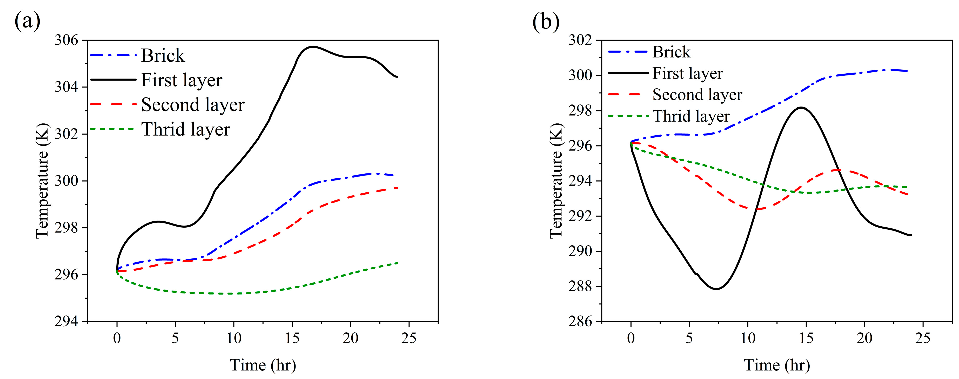
The configuration featuring three PCM layers places two thinner layers on the left and right sides of the brick—adjacent to the outdoor and indoor environments, respectively—and a thicker layer in the center. The temperature histories of these PCM layers and the brick’s solid structure under two distinct conditions, namely a hot summer day (22 July) and a cold winter day (28 January), as illustrated in Figure 4.
Based on Figure 4a, on the warm summer day of 22 July, the outermost PCM layer—located adjacent to the outdoor environment—exhibited the highest temperature fluctuations, reaching a peak of approximately 306 K (~33 °C) at 3 PM due to elevated outdoor temperatures and direct solar radiation. In contrast, the second and third PCM layers, positioned progressively inward, showed lower peak temperatures of approximately 299 K (~26 °C) and 296 K (~23 °C) at 3 PM and 12 AM, respectively. These findings demonstrate a sequential thermal absorption effect, with delayed heat transfer and reduced fluctuation as layers move inward. The third PCM layer, closest to the indoor space, remained relatively insulated from external conditions, primarily influenced by lower indoor temperatures. As a result, this layer experienced a gradual temperature decline until 5 AM, reflecting its role in maintaining cooler indoor conditions and highlighting the PCM’s capacity for thermal regulation and delayed heat transfer. Furthermore, the temperature peak for this layer does not occur in the afternoon (around 3 PM), as it is minimally affected by outdoor temperatures. The brick’s solid domain exhibited a smoother thermal response, with temperature fluctuations mirroring those of the second PCM layer and peaking around 300 K (~27 °C). The observed temperature gradient across the PCM layers underscores their effectiveness in impeding heat penetration and enhancing passive cooling, particularly in hot, arid climates.
Based on Figure 4b, on the cold winter day of 28 January, the first PCM layer, exposed to the outdoor air, experienced a temperature drop to approximately 288 K (~15 °C) by 7 AM. This decrease is attributed to the low ambient temperatures typical of winter and the effects of convective heat transfer. Meanwhile, the second and third PCM layers, positioned closer to the warmer indoor environment and insulated by the outer PCM, exhibited reduced temperature fluctuations and retained higher thermal levels. This behavior helps to maintain elevated temperatures in proximity to indoor spaces during cold winter days, highlighting the latent heat storage capability of the PCM. The temperature trend observed within the brick domain remains largely stable, exhibiting minimal fluctuations. This pattern aligns with the behavior of the second and third PCM layers, which reached their peak temperature of 300 K (~27 °C) in the afternoon, specifically after 3 PM. This observation highlights the contrast between the active thermal regulation provided by PCMs and the passive thermal inertia characteristic of conventional building materials, particularly under cold winter conditions. The reduced temperature fluctuations observed in the middle and right-hand side encapsulated PCM layers, along with the steady increase in the brick’s temperature, suggest that these layers are effective in minimizing heat loss and maintaining thermal equilibrium within the brick structure.
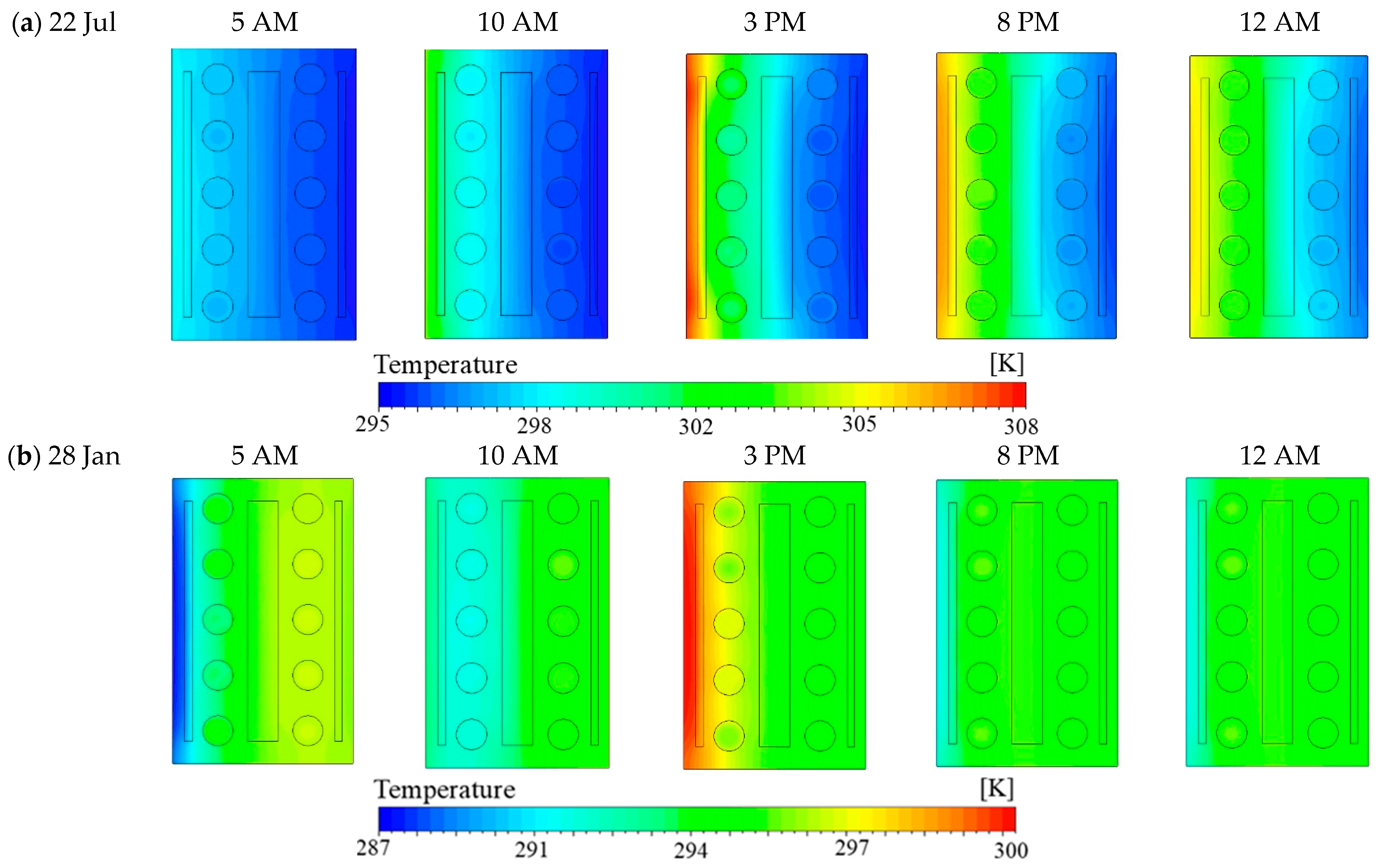
Figure 5 illustrates the temperature distribution at different hours throughout the day and night for both a hot summer day (22 July) and a cold winter day (28 January).
According to Figure 5a, on 22 July, the temperature gradient shows a steady increase from the outdoor environment toward the indoor area. This pattern continues until it reaches the first PCM layer, where a noticeable drop in temperature occurs, indicating the PCM’s role in resisting thermal penetration. Additionally, the temperature decreases from the center of the brick toward the rightmost (indoor-facing) section, as the indoor temperature is lower than the outdoor. This gradient remains evident throughout the day, from the leftmost (outdoor-facing) to the rightmost side. During the early morning hours (5 AM and 10 AM), the temperatures are relatively lower, with the outermost PCM layer exhibiting the coolest temperatures due to nighttime heat dissipation. By 3 PM, a significant thermal gradient emerges— both the rightmost surface and the first PCM layer reach temperatures of above 308 K (~35 °C), reflecting substantial thermal accumulation typical of summer conditions. Despite this, the first PCM layer effectively reduces heat transfer, as indicated by lower temperatures in the inner layers. At 8 PM and 12 AM, the envelope begins releasing stored heat, while internal layers remain cooler, aligning with indoor thermal conditions. This behavior illustrates the PCM’s thermal energy storage capacity and delayed heat release, demonstrating its role in preventing indoor overheating. The combined effect of thermal inertia and latent heat storage significantly enhances indoor thermal comfort and reduces cooling energy demand in hot climates.
According to Figure 5b, the temperature gradient on 28 January, during winter conditions, reveals a distinct pattern compared to summer. This variation is attributed to lower solar intensity and prevailing cold ambient temperatures. The gradient demonstrates a steady temperature decrease from the leftmost (outdoor-facing) section to the first PCM layer, followed by a gradual increase from the left-hand side to the right-hand side, spanning from the center of the brick toward the indoor environment. An exception to this trend occurs at 3 PM, when outdoor temperatures peak. At this time, the temperature on the left side of the brick (closer to the outdoor surface) is higher than that near the rightmost (indoor-facing) side. In the early hours of the day, particularly at 5 AM and 10 AM, the external surface registers significantly lower temperatures, approximately 287 K (~14 °C), indicating notable nocturnal heat loss to the cold outdoor environment. As solar radiation intensifies by mid-afternoon (3 PM), the outer surface temperature rises reaching up to 300 K (~27 °C). Despite this, the PCM layers facilitate a relatively uniform thermal distribution across the brick by absorbing and gradually releasing heat. During the nighttime hours (8 PM and 12 AM), heat retention becomes critical, and the PCM layers effectively minimize heat loss, sustaining elevated temperatures in the inner regions adjacent to indoor spaces. This behavior highlights the dual functionality of PCM in reducing cooling loads during summer and preserving heat during winter. To examine the impact of daily temperature variations, 
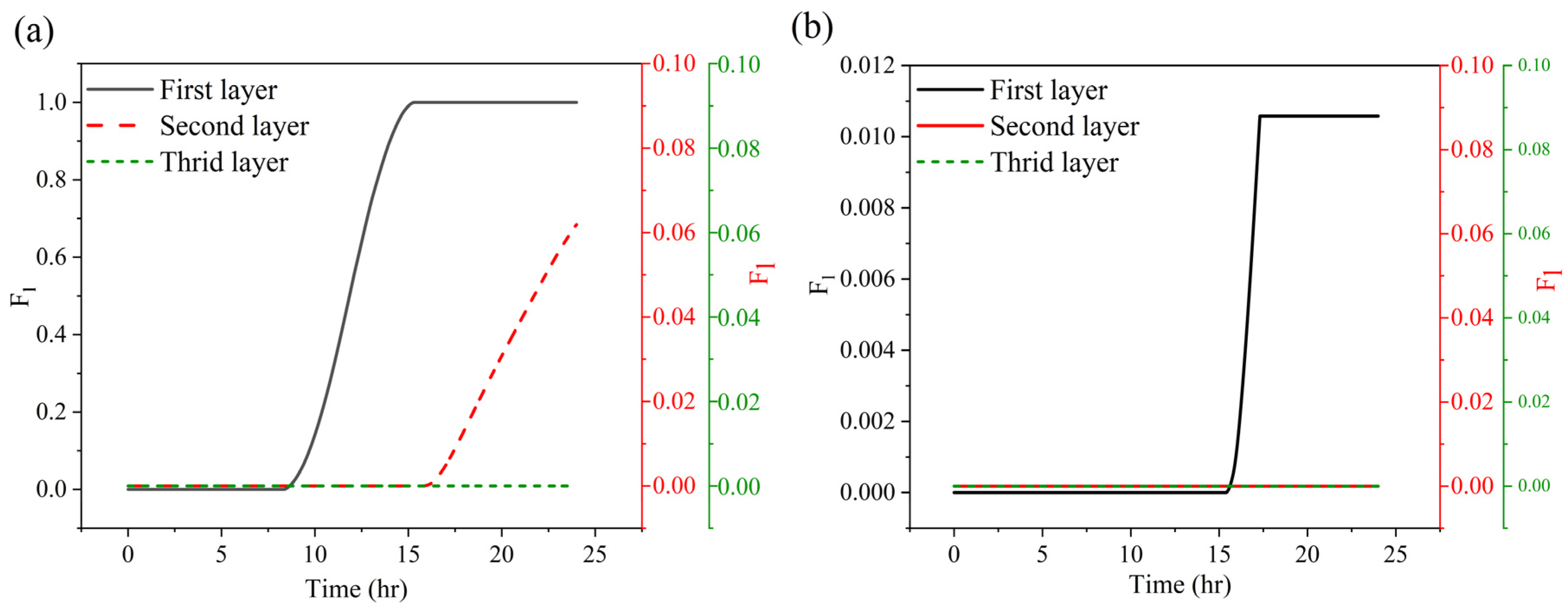
Figure 6 illustrates the liquid fraction evolution of the different encapsulated PCM layers on a hot summer day (22 July) and a cold winter day (28 January).
Based on Figure 6a, during the summer scenario, the first PCM layer—which is located closest to the outdoor environment—did not commence melting until approximately 9 AM, as its temperature remained significantly below the liquidus temperature of 302 K earlier in the day (see Figure 4a). The melting process gradually progressed, reaching its peak at around 3 PM, when the temperature of the first PCM layer was at its highest. At this point, the PCM within the first layer became fully liquefied and achieved a steady thermal state. The second phase PCM layer exhibited a delayed thermal response, initiating its phase change around 3 PM as its temperature crossed the liquefaction threshold. Meanwhile, the third PCM layer, positioned adjacent to the indoor environment, remained largely in the solid phase, indicating a notable thermal gradient across the PCM layers. This sequential melting behavior underscores the PCM’s capability to absorb and buffer external heat—particularly from the outermost layer inward—effectively delaying heat transfer into the indoor space. The fact that the third PCM layer remains predominantly solid, with a temperature lower than the adjacent brick layers, demonstrates its role in enhancing indoor thermal comfort and reducing cooling energy demand during high summer temperatures.
Figure 6b shows a significantly reduced phase transition across the PCM layers due to the lower ambient temperature of winter conditions. The first PCM layer undergoes a limited phase change, primarily between 3 PM and 4 PM, which corresponds to the period of peak outdoor temperature (refer to Figure 4b). Even at this peak, the phase transition remains partial, and the layer only reaches a steady state well below full liquefaction. The second and third PCM layers exhibit negligible variation in their liquid fractions, indicating that they remain predominantly in a solid state throughout the day. This observation is consistent with their recorded temperatures, which do not exceed the liquidus point of the PCM. As a result, these inner PCM layers serve primarily as passive thermal masses, rather than active phase-change. The limited extent of phase transition implies that, under winter conditions, the PCM’s primary role shifts toward minimizing heat loss rather than absorbing excess heat, which subsequently enhances the thermal insulation performance of the wall system. 
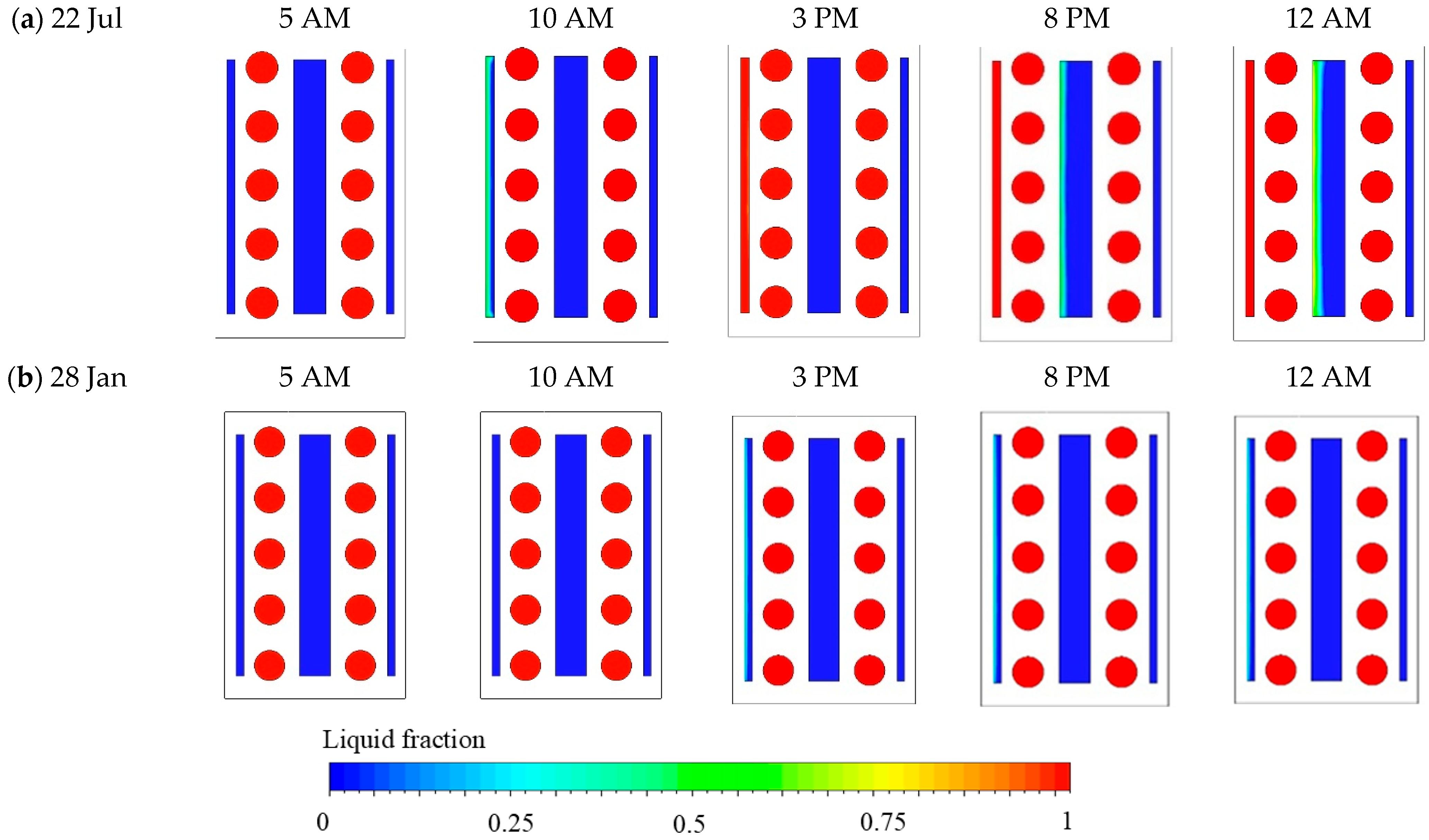
Figure 7 further illustrates the spatial distribution of liquid fraction contours at different times of day and night for both a hot summer day (22 July) and a cold winter day (28 January).
As indicated in Figure 7a, the first PCM layer—positioned adjacent to the outdoor environment—exhibits partial melting as early as 10 AM, with a distinct interface emerging between the solid and liquid phases. This observation corresponds with the gradual temperature rise originating from the leftmost side of the outdoor environment to the first PCM layer. By 3 PM, when external temperatures reach their peak, the first PCM layer reveals nearly complete melting, signifying substantial thermal energy absorption. In contrast, the inner PCM layers remain predominantly in the solid phase throughout the day. Their relatively lower temperatures—compared to the outermost layer—suggest their insulating role in delaying thermal penetration and mitigating indoor overheating. Between 8 PM and 12 AM, although outdoor temperatures begin to decrease, they remain above the PCM’s liquidus temperature. Consequently, partial melting begins to occur in the second PCM layer during these evening hours. However, the third PCM layer, located nearest to the indoor environment and subjected to the lowest thermal fluctuations, remains solid, functioning solely as a thermal absorber without undergoing a phase change. This behavior exemplifies the PCM’s effectiveness in mitigating daytime thermal penetration, regulating nocturnal temperatures, and enhancing indoor cooling efficiency during hot summer days.
According to Figure 7b, the PCM remains predominantly solid until 10 AM, with only a slight phase transition occurring near the outermost PCM layer around 3 PM. However, the system quickly stabilizes as it reaches a steady state condition. As temperatures drop in the evening, the PCM does not undergo further phase change, highlighting its role in maintaining thermal stability by minimizing excessive heat loss from the indoor environment to the colder outdoors.
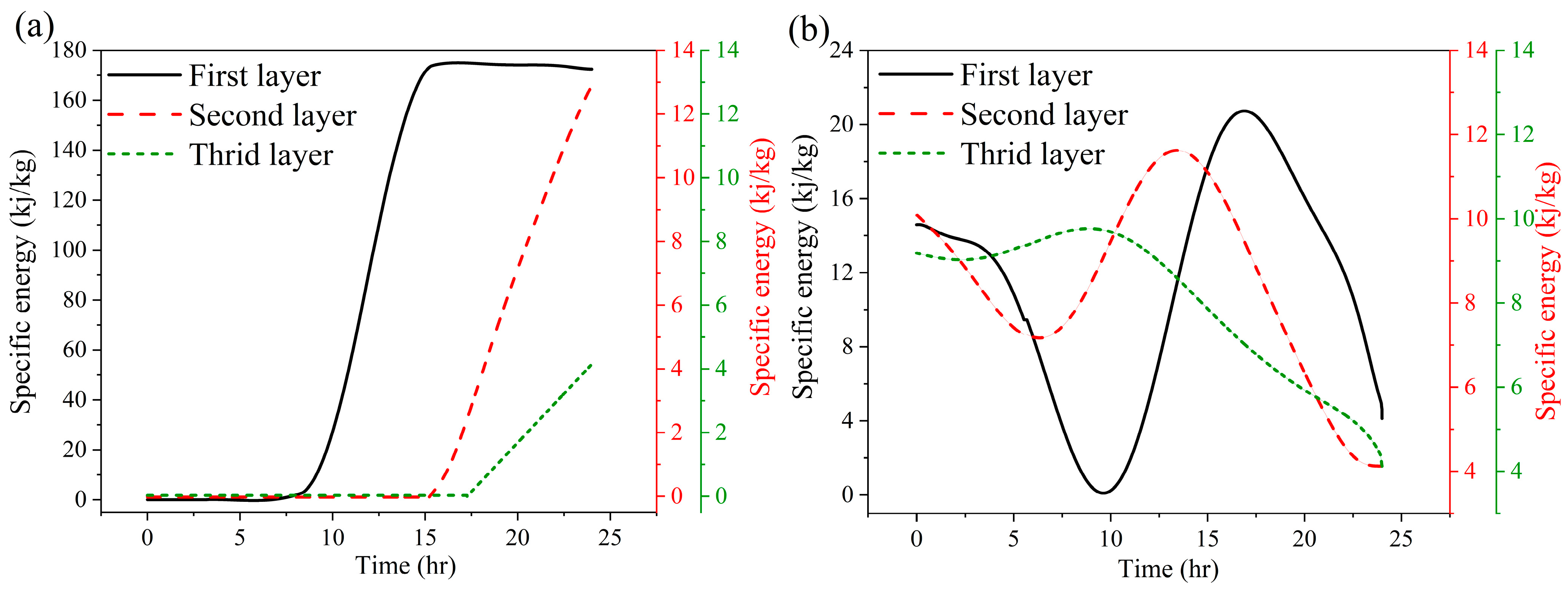
Figure 8 shows the specific absorbed energy for the encapsulated PCM layers on both a hot summer day (22 July) and a cold winter day (28 January).
Based on Figure 8a, the specific absorbed energy aligns closely with the temperature profile and liquid fraction trends discussed earlier. The first PCM layer, located adjacent to the outdoor environment on the leftmost side, demonstrates an initial increase in thermal energy absorption as sensible heat. However, this initial absorption is negligible compared to the latent thermal energy absorbed during phase transition after 9 AM. This initial negligible thermal energy absorption is due to the thermal equilibrium between the PCM and the outdoor environment, as well as the fact that its temperature remains below the PCM’s liquidus temperature until approximately 9 AM. Following this specified timeframe, a notable increase in specific energy absorption is observed, indicating the onset of latent heat storage form. This phenomenon is recognized as the second form of absorbed energy, which not only contributes to an increase in temperature but also initiates phase transitions. Therefore, the PCM phase transition and melting process are initiated, which continue until 3 PM, at which point the PCM completely melts. The specific absorbed energy reaches its peak at 170 kJ/kg, confirming the attainment of complete melting and reaching the steady-state condition. The sustained unity liquid fraction further confirms the steady-state condition and indicates that the PCM is fully melted from 3 PM to midnight. Given the estimated PCM mass of 3.26 × 10⁻² kg (as derived from its density in Table 2), the total thermal energy absorbed by the first layer is calculated to be approximately 5.54 kJ. The second PCM layer, with a mass of 13.04 × 10⁻² kg, begins to absorb thermal energy gradually from 3 PM onwards, reflecting the delayed onset of phase transition as temperatures rise to the PCM’s liquidus point. The specific absorbed energy peaks at around 13 kJ/kg, resulting in a total absorbed energy of approximately 1.67 kJ. While this value is only about one-third of the energy absorbed by the first layer, it underscores the second layer’s crucial role in impeding inward thermal penetration. The third PCM layer, positioned closest to the indoor environment, remains mostly solid throughout the day. It displays only a slight increase in specific energy absorption around 5 PM, associated with minimal latent heat storage. Given its similar mass to the first layer, the total energy absorbed is calculated to be approximately 0.13 kJ. The significantly lower energy absorption in the second and third PCM layers reflects both thermal resistance and the time lag in heat transfer from the outer layers inward.
According to Figure 8b, the specific absorbed energy trends during the cold winter day exhibit noticeable fluctuations, particularly during the early morning hours. These variations are most prominent in the leftmost PCM layers, which are in direct contact with the cold outdoor environment. This behavior is attributed to thermal energy dissipation to the outdoors and reflects the bidirectional nature of heat exchange between indoor and outdoor environments. The first PCM layer shows the most significant oscillations due to its direct exposure to ambient conditions. In the early morning, its specific absorbed energy decreases sharply as heat is lost to the cold surroundings. As the day progresses and outdoor temperatures increase slightly, a minor rise in specific energy is observed, corresponding to limited PCM melting in the afternoon. Based on its mass (3.26 × 10⁻² kg) and a peak specific energy of 23 kJ/kg, the maximum energy absorbed by this layer is approximately 0.75 kJ. However, this value drops to 0.16 kJ by 12 AM, which is lower than its initial energy state, indicating continuous thermal energy loss during the nighttime.
Initially, all PCM layers retain some residual thermal energy stored from the previous day, but the temperature gradient between the warmer interior and the colder exterior promotes energy dissipation over time. The second PCM layer exhibits a more stable energy profile and reduced fluctuations due to its insulation from the leftmost outdoor environment. This layer’s enhanced thermal mass effectively mitigates thermal dissipation. Given its higher mass (13.04 × 10⁻² kg) and peak specific energy of 12 kJ/kg, the total absorbed energy is approximately 1.56 kJ—double that of the first layer—highlighting its effectiveness in thermal stabilization. The third PCM layer, closest to the indoor space, exhibits a muted thermal response. It registers a peak specific energy of 9 kJ/kg around 10 AM, with a total energy absorption of 0.29 kJ, given its equal mass to the first layer. This energy is approximately half that of the first layer, underscoring the third layer’s limited exposure to external thermal influence. The reduced energy absorption and lower fluctuation amplitude highlight the effectiveness of the PCM system in enhancing thermal comfort during winter by reducing heating loads and preserving internal heat through the mitigation of heat loss across the building envelope.

3.2. Brick with Single Encapsulated PCM Layer

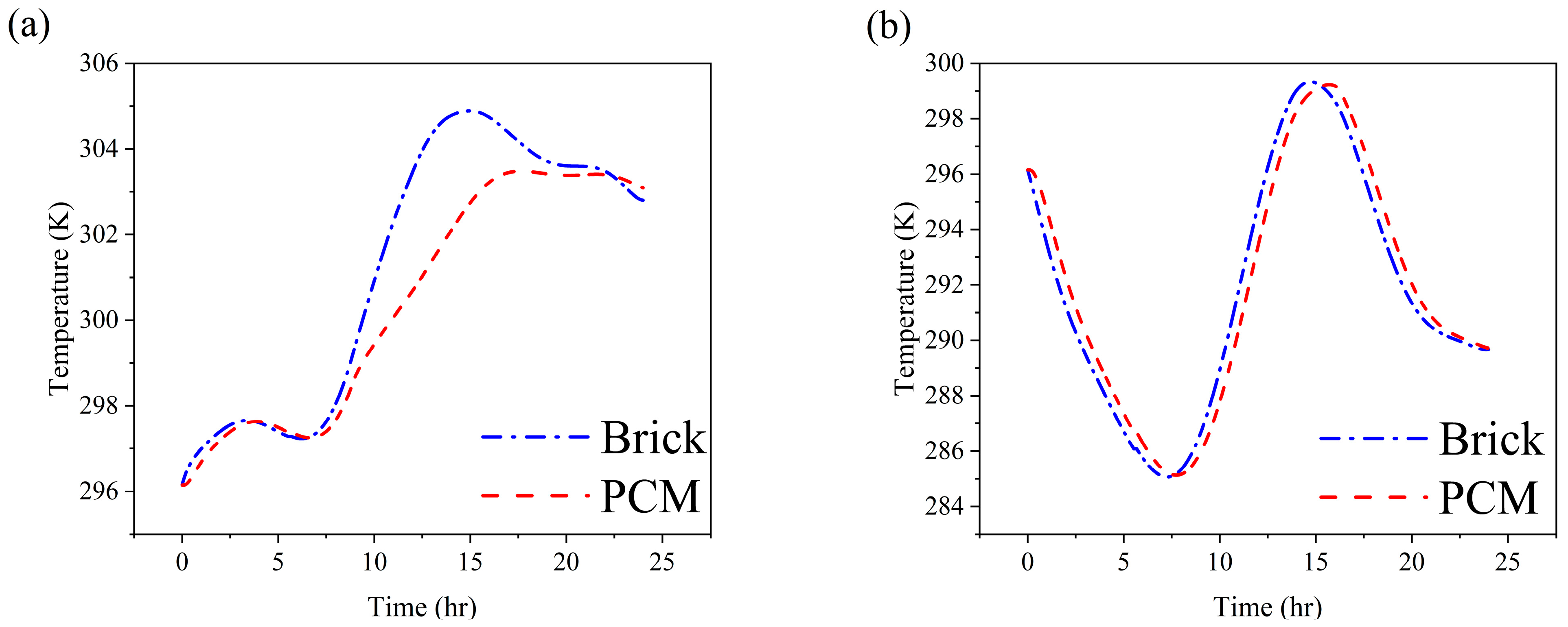
This configuration features a single encapsulated PCM layer strategically embedded at the central part of the brick structure. The analysis focuses on the temperature history of both the PCM layer and the surrounding solid brick material under two contrasting climatic conditions, namely a hot summer day (22 July) and a cold winter day (28 January), as depicted in Figure 9.
Figure 9a presents the averaged temperature history of the PCM and brick layers under summer conditions. The centrally embedded PCM layer exhibits a delayed and attenuated temperature response compared to the surrounding brick layers. Between 10 AM and 8 PM, the PCM reaches a maximum temperature of approximately 304 K (~31 °C) at 3 PM, whereas the brick layer peaks earlier at 1 PM with a slightly higher temperature of 305.5 K (~32 °C). Notably, this peak brick temperature exceeds that observed in the configuration with three PCM layers, emphasizing the enhanced thermal resistance provided by additional PCM layers in limiting heat penetration toward the indoor-facing side (see Figure 4a). The observed delay and the lower peak temperature of the single PCM layer are consistent with the behavior seen in the central PCM of the three-layer configuration. As the central layer, the PCM functions as an insulator, highlighting its essential role in absorbing and storing thermal energy during periods of high outdoor temperatures. This mechanism reduces thermal transmission through the brick and contributes to improved indoor thermal comfort. In contrast, Figure 9b illustrates the winter scenario, where both the PCM and brick layers exhibit nearly identical thermal profiles throughout the 24 h cycle. During the early morning cooling phase, when the leftmost (outdoor-facing) surface temperature drops below the initial temperature of the brick (until 9 AM), both materials experience a rapid temperature decline, reaching a minimum of approximately 285 K (~12 °C). This suggests the PCM provides limited resistance to heat loss during this period. Similarly, during the daytime heating phase leading up to 3 PM, both materials warm in tandem, with the PCM reaching a peak temperature nearly identical to that of the brick (~299 K or ~26 °C). The similar thermal response between the PCM and brick in this single-layer configuration indicates that under cold winter conditions, the PCM primarily acts as an insulator, offering minimal latent heat contribution. As a result, sensible heat storage dominates the system’s thermal performance, and the overall performance is nearly indistinguishable from that of the brick alone. This finding underscores the temperature-dependent nature of PCM functionality, where its thermal benefits diminish when ambient temperatures fall outside its phase change range.
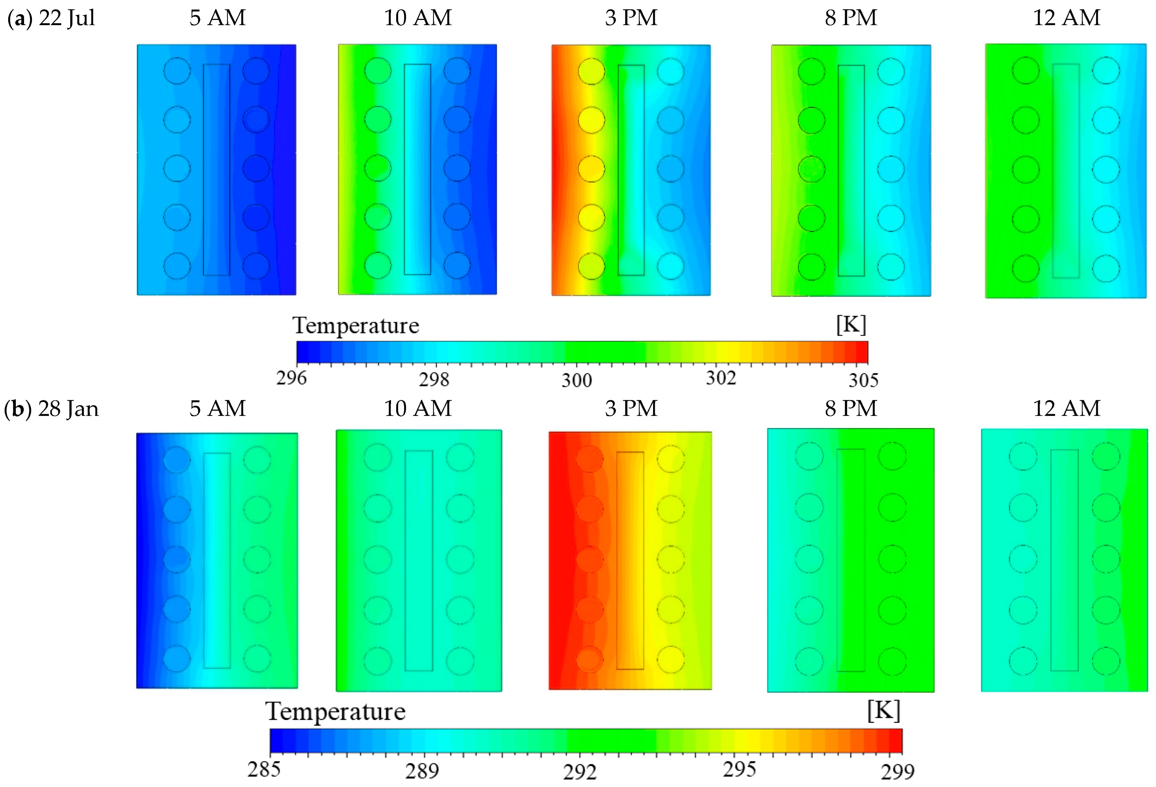
Figure 10 further illustrates the temperature distribution for both the hot summer day (22 July) and the cold winter day (28 January), offering deeper insight into the thermal behavior across the brick–PCM configuration.
According to Figure 10a, the temperature gradient during summer varies from approximately 296 K (~23 °C) at 5 AM to a peak of about 305 K (~32 °C) at 3 PM, with the highest temperatures observed on the brick’s leftmost (outdoor-facing) side. Notably, the thermal penetration from the outer surface to the brick’s center, particularly around the PCM layer, is significantly more pronounced in this single-layer configuration compared to the brick with three PCM layers (refer to Figure 5). This discrepancy stems from the absence of the first PCM layer, which acts as a thermal buffer by delaying heat propagation and absorbing it via latent heat storage. Without this layer, both the brick and PCM exhibit a more rapid temperature rise throughout the day. By 8 PM and 12 AM, the system begins to release stored heat, resulting in a rapid temperature decline from the outer layers to the environment. This cooling trend is more pronounced in the single-layer configuration due to insufficient insulation and limited thermal storage capacity on the exterior side, further highlighting the role of multiple PCM layers in moderating thermal discharge. Although the single encapsulated PCM layer exhibits some thermal mass and sustains elevated temperatures compared to early morning levels, its latent heat storage capacity is limited and less effective in maintaining thermal comfort than a multi-layer PCM system.
In contrast, Figure 10b illustrates the temperature field under winter conditions. During early morning hours, the temperature is lower on the leftmost (outdoor-facing) side than on the rightmost (indoor-facing) side due to colder external conditions. This trend continues until 5 AM. However, unlike the three-PCM-layer configuration, the temperature on the leftmost side exceeds that on the rightmost side by 10 AM, primarily due to the absence of the first PCM layer (see Figure 5). While temperatures peak around 3 PM, they remain significantly lower than summer values, and thermal penetration is more substantial due to the lack of latent heat buffering from an external PCM layer.
Despite this, the centrally placed PCM layer still provides a modest insulating effect, maintaining a relatively stable temperature gradient across the brick. By 8 PM and 12 AM, the system reaches thermal equilibrium, though with reduced heat retention compared to summer. The absence of both the first and third PCM layers—critical for insulation and temperature regulation—significantly reduces temperature and causes intense thermal fluctuations during winter. This seasonal variation in thermal behavior underscores the phase-dependent nature of PCM. Its efficiency in energy storage and release is significantly reduced during winter due to lower ambient temperatures that inhibit complete phase transition. This analysis highlights the PCM’s strong performance in mitigating extreme temperature fluctuations during summer, while offering moderate thermal regulation under colder winter conditions.
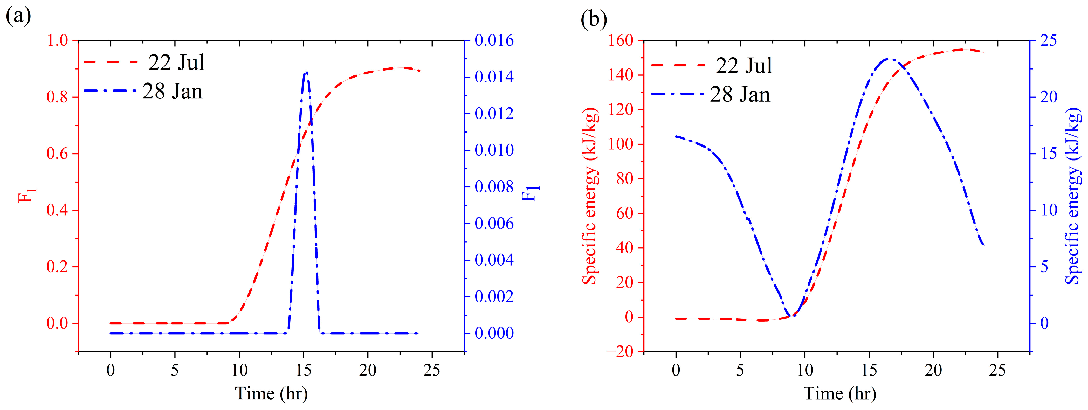
To further evaluate the impact of daily temperature fluctuations, Figure 11 presents the liquid fraction and specific absorbed energy of the single PCM layer on a hot summer day (22 July) and a cold winter day (28 January).
Regarding Figure 11a, under summer conditions, the PCM undergoes a gradual phase transition beginning around 10 AM—coinciding with the onset of melting observed in the first PCM layer of the three-layer configuration. In this single-layer setup, the centrally located PCM layer directly interacts with thermal penetration due to the absence of insulating layers (see Figure 6). As a result, the liquid fraction steadily increases throughout the day, reaching approximately 0.9 by 8 PM, indicating that steady-state conditions have been achieved. In contrast, the winter scenario reveals a sharp and limited phase transition at 3 PM, occurring only when the average temperature approaches the PCM’s liquidus point. The peak liquid fraction in this case is just 0.015, significantly lower than in the summer scenario. This discrepancy underscores the influence of ambient conditions on PCM behavior: elevated temperatures enable extended energy absorption and storage, whereas colder conditions lead to a rapid but minimal phase change. Additionally, unlike the three-layer PCM configuration—where the phase transition remains constant at a liquid fraction of zero—the liquid fraction in the single-layer PCM begins to decrease as temperatures fall, resulting in solidification. This behavior results from the absence of the first and third PCM layers that previously acted as thermal buffers. These findings underscore the importance of configuration design, illustrating that while PCM is effective in mitigating temperature fluctuations, its thermal performance is highly sensitive to climatic conditions and the extent of thermal insulation.
Based on Figure 11b, under summer conditions, the specific energy remains relatively constant during the early hours, with only minimal sensible heat absorption and no phase transition. Subsequently, a gradual increase begins around 10 AM, corresponding to the onset of phase change, during which latent heat is absorbed. This continues until the PCM reaches a peak specific energy level of approximately 150 kJ/kg under steady-state conditions. In contrast, the winter scenario exhibits a fluctuating specific energy profile. An initial decrease is observed up to 10 AM, resulting from lower ambient temperatures, followed by a sharp increase around 3 PM, peaking at approximately 24 kJ/kg as latent heat storage is briefly absorbed during a limited phase transition.
Given the PCM mass of 13.04 × 10 2   k g , the total absorbed energy in summer reaches approximately 19.56 kJ, whereas in winter, it is significantly lower at just 3.13 kJ. This disparity is directly linked to the behavior of the liquid fraction: in summer, a gradual phase transition enables sustained latent heat absorption, while in winter, the abrupt and limited phase transition limits the PCM’s energy storage potential. These findings underscore the critical role of the liquid fraction in determining the PCM’s thermal performance. The extent and duration of the phase transition largely dictate the material’s ability to regulate indoor temperature fluctuations under varying climatic conditions.
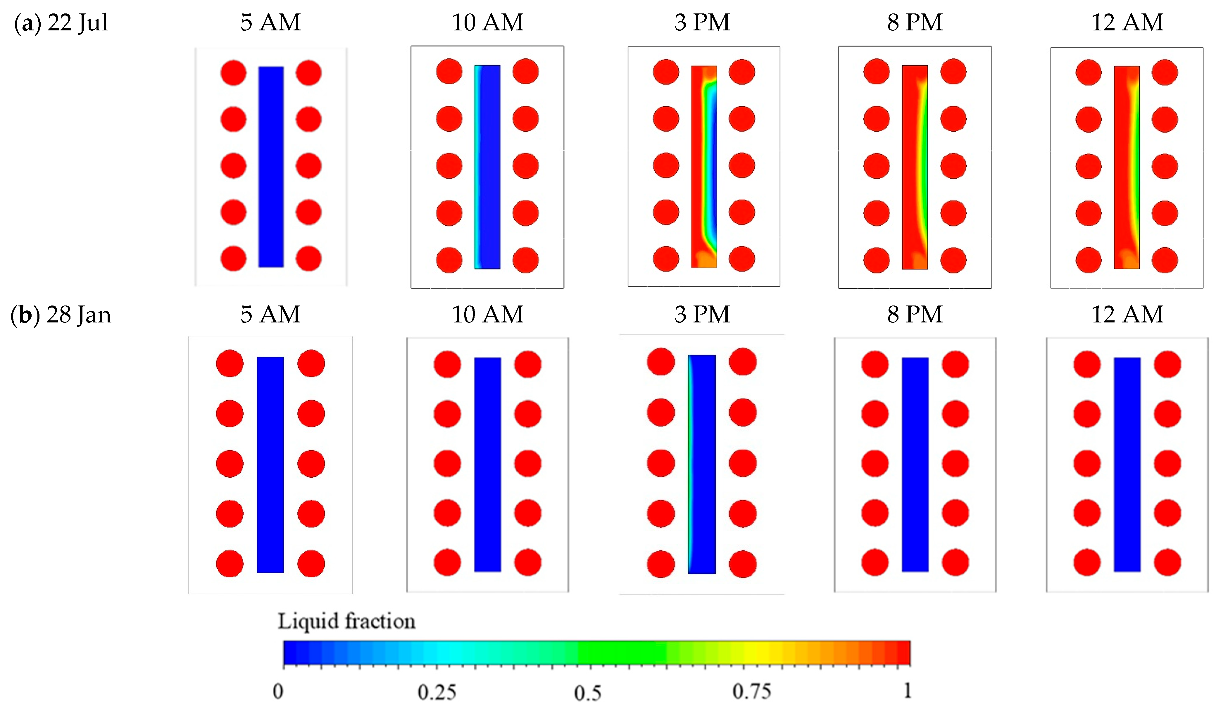
Figure 12 presents the liquid fraction contours at different times throughout the day and night for both a hot summer day (22 July) and a cold winter day (28 January).
Based on Figure 12a, the phase transition of the PCM on a hot summer day exhibits a progressive phase transition. This process begins around 10 AM as rising temperatures initiate the shift from sensible to latent heat storage, marked by the appearance of the solid–liquid interface. By 3 PM, at peak ambient temperature, a substantial portion of the PCM undergoes melting, driven by latent heat absorption. This thermal penetration from the leftmost (outdoor-facing) to the rightmost side induces a non-uniform melting pattern, with the top and middle sections transitioning first due to buoyancy-driven natural convection effects. The liquid fraction increases gradually along the PCM’s vertical centerline, reaching its maximum extent by 8 PM and stabilizing thereafter, indicating the attainment of steady-state conditions. By 12 AM, a partially melted state is still maintained due to the stored thermal energy, demonstrating the effectiveness of PCM not only in mitigating temperature fluctuations and thermal penetration during the day but also in preventing thermal dissipation at night.
According to Figure 12b, the PCM remains predominantly in a solid state during the early hours of the winter day. However, a minor phase transition is observed around 3 PM, corresponding to a temporary rise in temperature. Following this time, the liquid fraction field exhibits a rapid solidification by 8 PM. This behavior is primarily attributed to the limited thermal input from the leftmost side and the absence of adjacent PCM layers, which would otherwise serve as thermal buffers to reduce heat loss. Considering the temperature and liquid fraction distributions, the absence of lateral PCM layers on both the left-hand and right-hand sides significantly limits latent thermal storage and thermal insulation capabilities, thereby facilitating rapid thermal dissipation under cold climate conditions.

3.3. Simple Brick Without Encapsulated PCM Layer

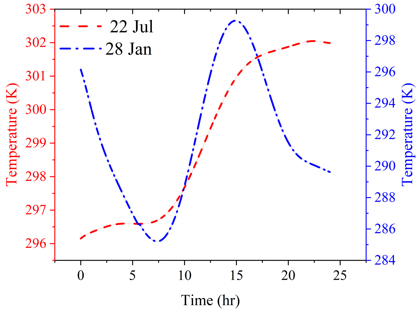
This section presents an analysis of a conventional clay brick with cavities, excluding any encapsulated PCM layers, under two contrasting climatic conditions: a hot summer day (22 July) and a cold winter day (28 January). Figure 13 illustrates the temperature history of the brick for both summer and winter scenarios.
As illustrated in Figure 13, during summer conditions, the brick’s temperature consistently increases from early morning, reaching its peak around 6 PM, and remains elevated into the night. This sustained temperature is due to prolonged ambient thermal penetration and heat retention, which differs from the bricks incorporated with PCM layers, demonstrating a temperature decline in the afternoon, particularly after 3 PM. In winter, a sharper temperature drop occurs during the early hours, reaching a minimum of approximately 285 K before noon, followed by a rise to about 299 K. While the temperature profile of the simple brick on a cold winter day is similar to that of a single PCM layer, it diverges significantly from the three-layer PCM. This comparison underscores the enhanced thermal regulation provided by multiple PCM layers, effectively minimizing temperature fluctuations and heat loss under cold conditions.
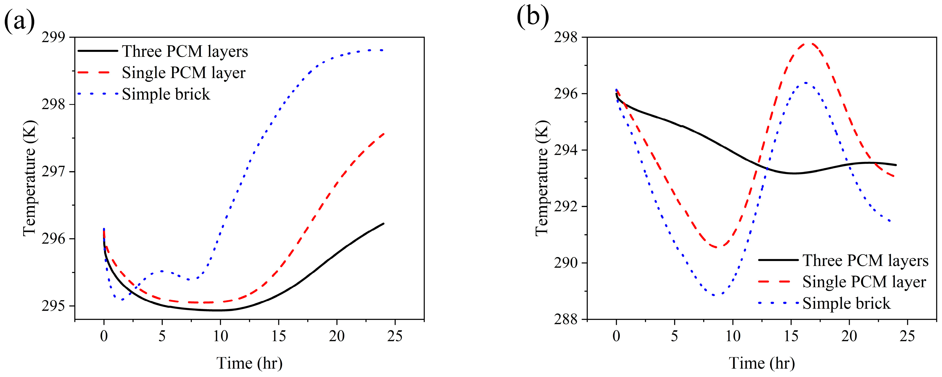
The advantages of PCM-based thermal regulation become particularly evident when examining the temperature histories of configurations incorporating PCM layers. In earlier analyses, the configuration with a single PCM layer exhibited a temperature plateau during the phase change process, indicating periods of latent heat absorption and storage. The implementation of three PCM layers further enhanced this effect by distributing thermal energy storage across multiple layers, thereby reducing peak temperatures and enhancing thermal buffering. In contrast, the absence of PCM results in pronounced heating and cooling cycles and greater thermal fluctuations. These uncontrolled variations may contribute to indoor thermal discomfort and increase energy demands for both cooling and heating.
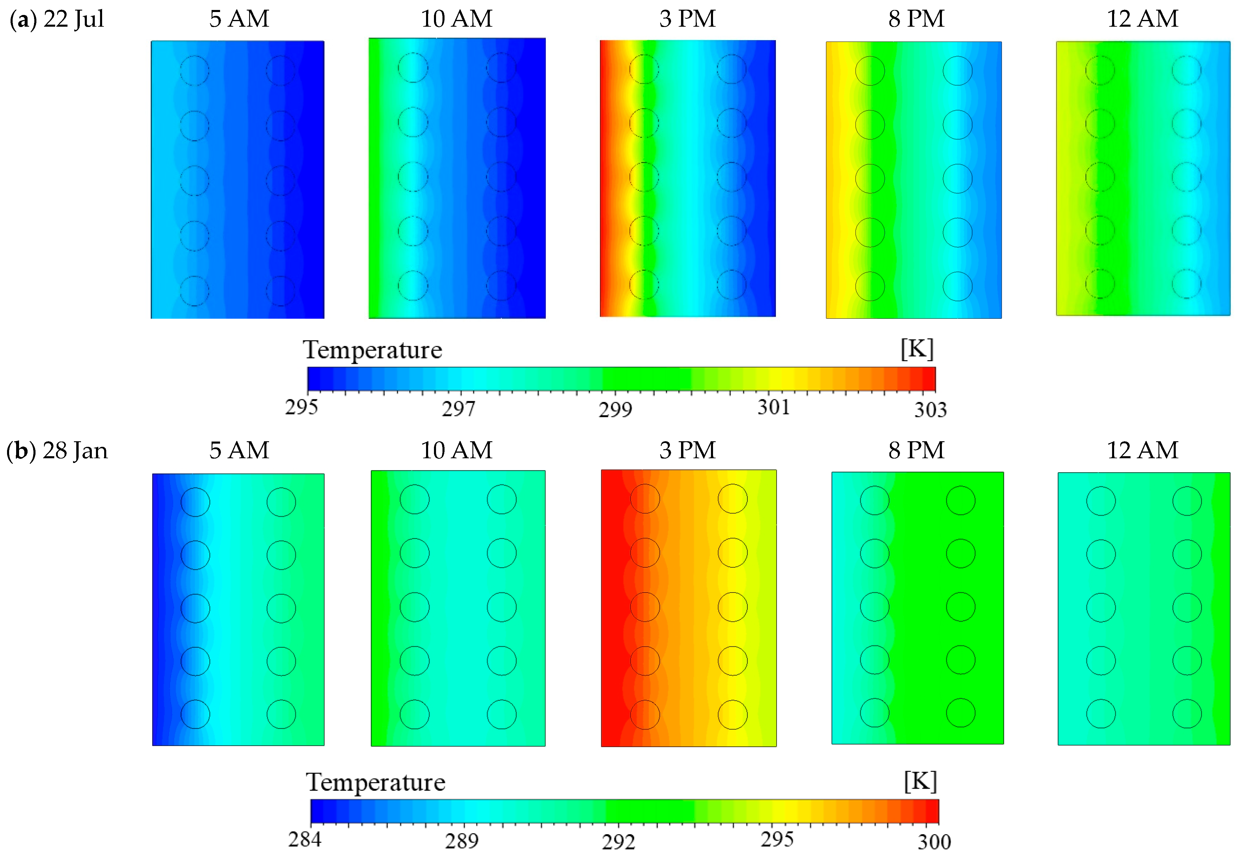
Figure 14 shows the temperature distribution for both hot summer (22 July) and cold winter (28 January) conditions, offering further insight into thermal behavior across configurations.
Based on Figure 14a, during a hot summer day, the temperature remains relatively low during in the early morning at 5 AM. As the outdoor temperature increases, the internal temperature of the brick rises, with the rightmost side reaching a peak of over 303 K (~30 °C) by 3 PM. Although a decrease in temperature is observed at 8 PM and 12 AM, it does not return to the early morning levels, indicating a degree of heat retention within the structure. However, in the absence of PCM layers, thermal penetration from the leftmost (outdoor-facing) side to the rightmost (indoor-facing) side is significantly more pronounced. This highlights the limited thermal buffering capacity of the plain brick configuration under high-temperature conditions.
In Figure 14b, the initial temperature distribution begins at a lower baseline, with early morning values around 284 K (~11 °C). As the day progresses, the temperature gradually increases, peaking near 300 K at approximately 3 PM. However, due to the lower ambient temperatures and reduced solar radiation during winter, heat loss occurs more rapidly. This results in a relatively uniform temperature distribution by nighttime. Compared to configurations incorporating PCM layers, this configuration exhibits a higher rate of heat exchange with the outdoor environment. These findings underscore the critical role of PCM in thermal regulation—particularly in mitigating abrupt temperature drops during winter—by functioning as an insulating barrier that slows down thermal dissipation.

3.4. Indoor Comfort Temperature Analysis

The integration of encapsulated PCM layers plays a vital role in moderating indoor temperatures throughout the day. The thermal penetration from the outdoor environment, from the leftmost side of the wall to the rightmost side toward the interior space, during the summer significantly affects room temperature and thermal comfort. Conversely, in the winter, thermal dissipation from the interior to the outdoor environment occurs. The incorporation of encapsulated PCM layers can mitigate thermal penetration in summer and dissipation in winter, thereby enhancing temperature retention and stabilization within the indoor environment and reducing energy demand as PCM layers play isolation role. An analysis of the indoor temperature history highlights the influence of these PCM layers on thermal comfort under two contrasting climatic conditions—a hot summer day (22 July) and a cold winter day (28 January)—as depicted in Figure 15.
Based on Figure 15a, the configuration utilizing simple bricks exhibits the most significant temperature fluctuations, with peak indoor temperatures exceeding 299 K (~26 °C). This is primarily due to direct thermal penetration from the leftmost side, as the absence of encapsulated PCM layers eliminates the insulating effects otherwise provided by latent heat storage. The introduction of a single PCM layer significantly reduces peak temperatures to approximately 297.5 K (~24 °C), demonstrating the PCM’s capacity to absorb and store thermal energy during peak heat periods. However, the most efficient thermal regulation is achieved with the configuration featuring three PCM layers, where the peak temperature is further reduced to around 296 K (~23 °C). This configuration exhibits superior thermal stability by effectively delaying and dampening heat transfer and thermal penetration from outdoor environment to the indoor by playing isolation role, which contributes to improved indoor comfort and reduced cooling energy demands.
Figure 15b presents a comparable trend under winter conditions, with the focus shifting toward thermal retention rather than thermal mitigation for the indoor environment by avoiding thermal dissipation from rightmost side to the leftmost side. The simple brick structure exhibits the lowest minimum temperatures, dropping to approximately 289 K (~16 °C), which may compromise thermal comfort and increase heating energy consumption, as it lacks a PCM layer that can act as an insulation layer and prevent thermal dissipation. Incorporating a single PCM layer helps moderate this decline, offering improved thermal retention during nighttime and avoiding thermal dissipation. Nevertheless, the three-layer PCM configuration provides the most stable temperature profile, minimizing thermal fluctuations and maintaining a near-constant indoor temperature throughout the day. This underscores the benefits of multi-layer PCM integration in reducing heating loss during winter while stabilizing the indoor thermal environment. The data indicate that encapsulated PCM layers significantly enhance thermal comfort when compared to configurations that do not incorporate PCM, as they serve as an effective insulation. These layers effectively prevent thermal penetration, thereby mitigating peak temperatures during the summer months and reducing heat loss and thermal dissipation in winter, which in turn reduces the indoor temperature drop. This underscores the importance of encapsulated PCM as an effective passive thermal management strategy.

4. Conclusions

This study systematically investigated the thermal performance of bricks integrated with encapsulated PCMs and evaluates their impact on indoor thermal comfort. The analysis included an evaluation of temperature history, liquid fraction evolution, and energy absorption, providing a comprehensive assessment of thermal regulation under contrasting climatic conditions—specifically, a hot summer day (22 July) and a cold winter day (28 January) in Tehran’s climate. Based on the results, the following conclusions are drawn.
Summer scenario: The simple brick configuration exhibited the highest peak indoor temperature, indicating a significant heat penetration. Incorporating a single PCM layer effectively reduced peak temperatures, demonstrating the effectiveness of latent heat absorption in mitigating overheating. The three-layer PCM configuration yielded the most stable indoor temperature, achieving a notable reduction in peak temperature and significantly enhancing thermal comfort while lowering cooling energy demand.
Winter scenario: The simple brick resulted in the lowest indoor temperatures, leading to potential thermal discomfort. The incorporation of a single PCM layer enhances thermal retention, mitigating nighttime temperature drops, and stabilizing the indoor environment. The three-layer PCM configuration proved most effective in minimizing thermal losses and maintaining indoor temperatures, thereby improving occupant comfort and reducing heating energy requirements.
PCM layer performance in summer: In the three-layer PCM configuration, the first layer—exposed directly to outdoor conditions—exhibited the highest melting rate due to its greater energy absorption. The second and third layers, located deeper within the wall, played a primarily insulating role with lower latent heat exchange, thereby limiting further thermal penetration and enhancing overall insulation.
PCM layer performance in winter: In the three-layer PCM configuration, thermal fluctuations were influenced by bidirectional heat exchange between the indoor and outdoor environments. The first PCM layer experienced the most pronounced energy variation, reaching its peak in the afternoon and declining by midnight due to heat loss. The second PCM layer, more insulated and possessing greater thermal mass, absorbed energy at nearly twice the rate of the first layer, contributing significantly to thermal stabilization. The third PCM layer, positioned closest to the indoor environment, exhibited minimal fluctuations and served to buffer indoor temperature, thereby maintaining internal thermal stability.
It should be noted, in this study, a singular PCM layer is centrally integrated within the brick structure, representing a streamlined and practical strategy for PCM implementation, particularly suitable for retrofitting applications. This configuration is evaluated against a three-layer wall design in which PCM is positioned along the inner and outer peripheries of the brick core. Although the structural designs differ, both configurations are subjected to identical thermal boundary conditions, thereby facilitating a meaningful comparison regarding thermal performance. The aim of this comparison is not to achieve architectural equivalence, but to assess the impact of various PCM placement strategies—concentrated at the center versus distributed at the periphery—on the wall’s capability to regulate temperature fluctuations and improve thermal comfort, as well as retard thermal penetration and dissipation. The standard clay brick without PCM serves as a control to evaluate the thermal enhancements provided by each design.

5. Future Study

In our research, we aim to systematically investigate the arrangement of encapsulated PCMs within clay bricks. This arrangement is intended to improve thermal comfort by reducing thermal penetration on hot summer days and minimizing thermal dissipation during cold winter days. However, like all CFD simulations, our study encountered specific limitations that could be explored further in future research. Firstly, we recommend exploring other paraffin-based PCMs and alternatives within the RT-line series, focusing on varying melting and solidification temperature ranges, as well as latent heat capacities, to identify the most optimal PCM for effective thermal regulation. Additionally, it is advisable to examine circular encapsulated PCMs within clay bricks featuring rectangular air cavities, which are recognized as widely accepted construction materials. Furthermore, incorporating solar radiation into the simulation, or modeling it as a periodic equivalent heat flux, could significantly enhance the accuracy of the simulations. Lastly, as discussed in the literature survey, paraffin-based PCMs are not only widely accessible and cost-effective but also possess a reasonable lifecycle. Therefore, we recommend conducting experimental investigations on encapsulated PCMs in clay bricks with various arrangements and different types of paraffin-based PCMs to demonstrate the practical application of PCM integration in construction materials.

Author Contributions

Conceptualization, F.G. and M.M.; methodology, F.G. and M.M.; software, F.G.; validation, F.G. and S.R.M.; formal analysis, F.G.; investigation, F.G. and S.R.M.; resources, F.G. and M.M.; data curation, F.G., M.M. and M.S.; writing—original draft preparation, F.G. and M.S.; writing—review and editing, M.M., M.S. and S.R.M.; visualization, F.G.; supervision, M.M. and M.S.; project administration, M.M. and M.S.; funding acquisition, F.G. and M.S. All authors have read and agreed to the published version of the manuscript.

Funding

This research received no external funding.

Data Availability Statement

The original contributions presented in this study are included in the article. Further inquiries can be directed to the corresponding author.

Conflicts of Interest

The authors declare no conflict of interest.

Nomenclature

Symbols
A Source term used in the momentum equation ( P a / m )
C Mushy zone constant ( P a . s / m 2 )
C p Specific heat ( J / k g . K )
F l Liquid fraction
k Thermal conductivity ( W / m . K )
L Latent heat of fusion ( J / k g )
T Temperature ( K )
q Heat flux ( W / m 2 )
T m Melting temperature ( K )
h Heat transfer coefficient ( W / m 2 · K )
Greek
β Thermal expansion coefficient ( 1 / K )
μ Viscosity ( P a · s )
ρ Density ( k g / m 3 )
Abbreviations
CFDComputational Fluid Dynamic
PCMPhase Change Material
TESThermal Energy Storage
Subscripts
sSolid
fFluid

References

  1. Mahdi, J.M.; Mohammed, H.I.; Talebizadehsardari, P.; Ghalambaz, M.; Sh Majdi, H.; Khan, A.; Yaïci, W.; Giddings, D. Simultaneous and consecutive charging and discharging of a PCM-based domestic air heater with metal foam. Appl. Therm. Eng. 2021, 197, 117408. [Google Scholar] [CrossRef]
  2. Hooftman, N.; Oliveira, L.; Messagie, M.; Coosemans, T.; Van Mierlo, J. Environmental analysis of petrol, diesel and electric passenger cars in a Belgian urban setting. Energies 2016, 9, 84. [Google Scholar] [CrossRef]
  3. Yadav, A.; Samykano, M.; Pandey, A.K.; Natarajan, S.K.; Vasudevan, G.; Muthuvairavan, G.; Suraparaju, S.K. Sustainable phase change material developments for thermally comfortable smart buildings: A critical review. Process Saf. Environ. Prot. 2024, 191, 1918–1955. [Google Scholar] [CrossRef]
  4. Jiao, K.; Lu, L.; Zhao, L.; Wang, G. Towards Passive Building Thermal Regulation: A State-of-the-Art Review on Recent Progress of PCM-Integrated Building Envelopes. Sustainability 2024, 16, 6482. [Google Scholar] [CrossRef]
  5. El Majd, A.; Sair, S.; Ait Ousaleh, H.; Berardi, U.; Moulakhnif, K.; Belouaggadia, N.; Younsi, Z.; El Bouari, A. Advancing PCM research in building efficiency: A comprehensive investigation into PCM selection and critical integration strategies. J. Build. Eng. 2024, 96, 110485. [Google Scholar] [CrossRef]
  6. Kim, Y.U.; Yun, B.Y.; Jin, D.; Kim, S. Enhancing thermal efficiency in sustainable building materials: Carbon-reinforced cementitious composites with microencapsulated and impregnated PCM. J. Build. Eng. 2025, 108, 112887. [Google Scholar] [CrossRef]
  7. Ait Laasri, I.; Es-Sakali, N.; Charai, M.; Mghazli, M.O.; Outzourhit, A. Recent progress, limitations, and future directions of macro-encapsulated phase change materials for building applications. Renew. Sustain. Energy Rev. 2024, 199, 114481. [Google Scholar] [CrossRef]
  8. Reyez-Araiza, J.L.; Pineda-Piñón, J.; López-Romero, J.M.; Gasca-Tirado, J.R.; Arroyo Contreras, M.; Jáuregui Correa, J.C.; Apátiga-Castro, L.M.; Rivera-Muñoz, E.M.; Velazquez-Castillo, R.R.; Pérez Bueno, J.d.J.; et al. Thermal energy storage by the encapsulation of phase change materials in building elements—A review. Materials 2021, 14, 1420. [Google Scholar] [CrossRef]
  9. Tahmasbi, M.; Siavashi, M.; Karimi, A.R.; Tousi, R.; Keshtkaran, A.H. The effects of fins number, metal foam, and helical coil on the thermal storage enhancement of the phase change material: An experimental study. Appl. Therm. Eng. 2024, 253, 123780. [Google Scholar] [CrossRef]
  10. Bhamare, D.K.; Rathod, M.K.; Banerjee, J.; Arıcı, M. Investigation of the Effect of Air Layer Thickness on the Thermal Performance of the PCM Integrated Roof. Buildings 2023, 13, 488. [Google Scholar] [CrossRef]
  11. Lamrani, B.; Johannes, K.; Kuznik, F. Phase change materials integrated into building walls: An updated review. Renew. Sustain. Energy Rev. 2021, 140, 110751. [Google Scholar] [CrossRef]
  12. Du, K.; Calautit, J.; Wang, Z.; Wu, Y.; Liu, H. A review of the applications of phase change materials in cooling, heating and power generation in different temperature ranges. Appl. Energy 2018, 220, 242–273. [Google Scholar] [CrossRef]
  13. Du, K.; Calautit, J.; Eames, P.; Wu, Y. A state-of-the-art review of the application of phase change materials (PCM) in Mobilized-Thermal Energy Storage (M-TES) for recovering low-temperature industrial waste heat (IWH) for distributed heat supply. Renew. Energy 2021, 168, 1040–1057. [Google Scholar] [CrossRef]
  14. Masood, U.; Haggag, M.; Hassan, A.; Laghari, M. A Review of Phase Change Materials as a Heat Storage Medium for Cooling Applications in the Built Environment. Buildings 2023, 13, 1595. [Google Scholar] [CrossRef]
  15. Li, G.; Hwang, Y.; Radermacher, R. Cold Thermal Energy Storage Materials and Applications Toward Sustainability. In Energy Solutions to Combat Global Warming; Zhang, X., Dincer, I., Eds.; Lecture Notes in Energy; Springer International Publishing: Cham, Switzerland, 2017; Volume 33, pp. 67–117. ISBN 978-3-319-26950-4. [Google Scholar] [CrossRef]
  16. Barzin, R.; Chen, J.J.J.; Young, B.R.; Farid, M.M. Application of PCM underfloor heating in combination with PCM wallboards for space heating using price based control system. Appl. Energy 2015, 148, 39–48. [Google Scholar] [CrossRef]
  17. Dora, S.; Kuznik, F.; Mini, K.M. A novel PCM-based foam concrete for heat transfer in buildings -Experimental developments and simulation modelling. J. Energy Storage 2025, 105, 114625. [Google Scholar] [CrossRef]
  18. Luo, Z.; Xu, H.; Lou, Q.; Feng, L.; Ni, J. GPU-accelerated lattice Boltzmann simulation of heat transfer characteristics of porous brick roof filled with phase change materials. Int. Commun. Heat Mass Transf. 2020, 119, 104911. [Google Scholar] [CrossRef]
  19. Li, C.; Tang, H. Phase change material window for dynamic energy flow regulation: Review. Renew. Sustain. Energy Rev. 2024, 189, 113937. [Google Scholar] [CrossRef]
  20. Rehman, A.U.; Sheikh, S.R.; Kausar, Z.; McCormack, S.J. Numerical Simulation of a Novel Dual Layered Phase Change Material Brick Wall for Human Comfort in Hot and Cold Climatic Conditions. Energies 2021, 14, 4032. [Google Scholar] [CrossRef]
  21. Hamidi, Y.; Malha, M.; Bah, A. Analysis of the thermal behavior of hollow bricks walls filled with PCM: Effect of PCM location. Energy Rep. 2021, 7, 105–115. [Google Scholar] [CrossRef]
  22. Dabiri, S.; Mehrpooya, M.; Nezhad, E.G. Latent and sensible heat analysis of PCM incorporated in a brick for cold and hot climatic conditions, utilizing computational fluid dynamics. Energy 2018, 159, 160–171. [Google Scholar] [CrossRef]
  23. Mukram, T.A.; Daniel, J. Performance evaluation of a novel cement brick filled with micro-PCM used as a thermal energy storage system in building walls. J. Energy Storage 2024, 77, 109910. [Google Scholar] [CrossRef]
  24. Javidan, M.; Asgari, M.; Gholinia, M.; Nozari, M.; Asgari, A.; Ganji, D.D. Thermal energy storage inside the chamber with a brick wall using the phase change process of paraffinic materials: A numerical simulation. Theor. Appl. Mech. Lett. 2022, 12, 100329. [Google Scholar] [CrossRef]
  25. Younsi, Z.; Naji, H. Numerical simulation and thermal performance of hybrid brick walls embedding a phase change material for passive building applications. J. Therm. Anal. Calorim. 2020, 140, 965–978. [Google Scholar] [CrossRef]
  26. Rai, A.C. Energy performance of phase change materials integrated into brick masonry walls for cooling load management in residential buildings. Build. Environ. 2021, 199, 107930. [Google Scholar] [CrossRef]
  27. Abbas, H.M.; Jalil, J.M.; Ahmed, S.T. Experimental and numerical investigation of PCM capsules as insulation materials inserted into a hollow brick wall. Energy Build. 2021, 246, 111127. [Google Scholar] [CrossRef]
  28. Chihab, Y.; Bouferra, R.; Garoum, M.; Essaleh, M.; Laaroussi, N. Thermal inertia and energy efficiency enhancements of hollow clay bricks integrated with phase change materials. J. Build. Eng. 2022, 53, 104569. [Google Scholar] [CrossRef]
  29. Dellagi, A.; Ayed, R.; Bouadila, S.; Guizani, A. Computational and experimental analysis of PCM-infused brick for sustainable heat regulation. J. Build. Phys. 2024, 48, 222–243. [Google Scholar] [CrossRef]
  30. Huang, Y.; Alekhin, V.N.; Hu, W.; Pu, J. Adaptability Analysis of Hollow Bricks with Phase-Change Materials Considering Thermal Performance and Cold Climate. Buildings 2025, 15, 590. [Google Scholar] [CrossRef]
  31. Jia, C.; Geng, X.; Liu, F.; Gao, Y. Thermal behavior improvement of hollow sintered bricks integrated with both thermal insulation material (TIM) and Phase-Change Material (PCM). Case Stud. Therm. Eng. 2021, 25, 100938. [Google Scholar] [CrossRef]
  32. Bondareva, N.S.; Sheremet, M.A. A Numerical Study of Heat Performance of Multi-PCM Brick in a Heat Storage Building. Mathematics 2023, 11, 2825. [Google Scholar] [CrossRef]
  33. Hamidi, Y.; Aketouane, Z.; Malha, M.; Bruneau, D.; Bah, A.; Goiffon, R. Integrating PCM into hollow brick walls: Toward energy conservation in Mediterranean regions. Energy Build. 2021, 248, 111214. [Google Scholar] [CrossRef]
  34. Bondareva, N.S.; Sheremet, M.A. Influence of phase change material melting point and its location on heat and mass transfer in a brick. J. Energy Storage 2021, 42, 103122. [Google Scholar] [CrossRef]
  35. Tunçbilek, E.; Arıcı, M.; Bouadila, S.; Wonorahardjo, S. Seasonal and annual performance analysis of PCM-integrated building brick under the climatic conditions of Marmara region. J. Therm. Anal. Calorim. 2020, 141, 613–624. [Google Scholar] [CrossRef]
  36. Rashid, F.L.; Dhaidan, N.S.; Al-Obaidi, M.; Mohammed, H.I.; Mahdi, A.J.; Ameen, A.; Parveen, R.; Kezzar, M.; Nazari, S.; Galal, A.M. Latest progress in utilizing phase change materials in bricks for energy storage and discharge in residential structures. Energy Build. 2025, 330, 115327. [Google Scholar] [CrossRef]
  37. Bondareva, N.S.; Sheikholeslami, M.; Sheremet, M.A. The influence of external temperature and convective heat exchange with an environment on heat transfer inside phase change material embedded brick. J. Energy Storage 2021, 33, 102087. [Google Scholar] [CrossRef]
  38. Mahdaoui, M.; Hamdaoui, S.; Ait Msaad, A.; Kousksou, T.; El Rhafiki, T.; Jamil, A.; Ahachad, M. Building bricks with phase change material (PCM): Thermal performances. Constr. Build. Mater. 2021, 269, 121315. [Google Scholar] [CrossRef]
  39. Taj, S.A.; Khalid, W.; Nazir, H.; Khan, A.; Sajid, M.; Waqas, A.; Hussain, A.; Ali, M.; Zaki, S.A. Experimental investigation of eutectic PCM incorporated clay brick for thermal management of building envelope. J. Energy Storage 2024, 84, 110838. [Google Scholar] [CrossRef]
  40. Qureshi, Z.A.; Al-Omari, S.A.B.; Elnajjar, E.; Al-Ketan, O.; Al-Rub, R.A. Using triply periodic minimal surfaces (TPMS)-based metal foams structures as skeleton for metal-foam-PCM composites for thermal energy storage and energy management applications. Int. Commun. Heat Mass Transf. 2021, 124, 105265. [Google Scholar] [CrossRef]
  41. Refaey, H.A.; Abdo, S.; Saidani-Scott, H.; El-Shekeil, Y.A.; Bendoukha, S.; Barhoumi, N.; Abdelrahman, M.A. Thermal regulation of photovoltaic panels using PCM with multiple fins configuration: Experimental study with analysis. Therm. Sci. Eng. Prog. 2024, 49, 102457. [Google Scholar] [CrossRef]
  42. Alqallaf, H.J.; Alawadhi, E.M. Concrete roof with cylindrical holes containing PCM to reduce the heat gain. Energy Build. 2013, 61, 73–80. [Google Scholar] [CrossRef]
Figure 1. (a) The proposed clay brick model with boundary conditions and the following components: 1, 2, and 3—encapsulated PCM layers; 4—air cavities; 5—clay brick. (b) Equivalent temperature profile of Tehran for hot summer day (22 July) and cold winter day (28 January).
Fluids 10 00181 g001
Figure 2. Mesh configuration with details of air cavity and PCM layers.
Fluids 10 00181 g002
Figure 3. A comparison between the current CFD simulation results and the numerical and experimental findings reported by Alqallaf and Alawadhi [42] for indoor temperature profiles under Kuwait’s climatic conditions.
Fluids 10 00181 g003
Figure 4. Averaged temperature history for brick and PCM layers on (a) a hot summer day (22 July) and (b) a cold winter day (28 January).
Fluids 10 00181 g004
Figure 5. Temperature distribution on (a) a hot summer day (22 July) and (b) a cold winter day (28 January).
Fluids 10 00181 g005
Figure 6. F l for (a) hot summer day (22 July); (b) cold winter day (28 January).
Fluids 10 00181 g006
Figure 7. F l contour for (a) a hot summer day (22 July) and (b) a cold winter day (28 January).
Fluids 10 00181 g007
Figure 8. Specific absorbed energy for (a) a hot summer day (22 July) and (b) a cold winter day (28 January).
Fluids 10 00181 g008
Figure 9. Averaged temperature history for brick and PCM layer: (a) hot summer day (22 July); (b) cold winter day (28 January).
Fluids 10 00181 g009
Figure 10. Temperature field: (a) hot summer day (22 July); (b) cold winter day (28 January).
Fluids 10 00181 g010
Figure 11. (a) F l (b) specific energy for PCM on summer and winter days.
Fluids 10 00181 g011
Figure 12. F l contours for (a) hot summer day (22 July) and (b) cold winter day (28 January).
Fluids 10 00181 g012
Figure 13. Averaged temperature history for the brick.
Fluids 10 00181 g013
Figure 14. Temperature field for (a) a hot summer day (22 July) and (b) a cold winter day (28 January).
Fluids 10 00181 g014
Figure 15. Averaged temperature history of indoor space: (a) hot summer day (22 July) and (b) cold winter day (28 January).
Fluids 10 00181 g015
Table 1. Dimensional properties of various components of the geometry.
First and Third PCM LayersSecond PCM LayerCapsulesAir Cavity
Width (mm)Length (mm)Width (mm)Length (mm)Thickness (mm)Diameter (mm)
5160201600.620
Table 2. Thermophysical properties of the employed material [22,41].
ParameterPCMAirBrickAluminum
Density, ρ   k g / m 3 8151.12519762700
Specific heat, C p J / k g · K 20001006.43835871
Thermal conductivity, k W / m · K 0.20.02420.77202.4
Pure melting heat, H l J / k g 165,000---
Liquidus temperature, T l i q K 302.15---
Solidus temperature, T s o l K 300.15---
Table 3. Boundary and initial conditions summary.
Condition DescriptionIndoorOutdoor
Free convection W / m 2 · K 7.697.69
Initial temperature K 293.15296.15
Equivalent temperature profile (22 July)-Equation (9)
Equivalent temperature profile (28 January)-Equation (10)
Table 4. Mesh levels specification.
Mesh TypeNumber of ElementsInterface Element Size (mm)Average Orthogonal QualityBrick Temperature (22 Jul)Brick Temperature (28 Jan)
Coarse52,5000.70.991301.24298.57
Medium100,2000.50.992301.18298.47
Fine271,6000.30.994301.12298.39
Disclaimer/Publisher’s Note: The statements, opinions and data contained in all publications are solely those of the individual author(s) and contributor(s) and not of MDPI and/or the editor(s). MDPI and/or the editor(s) disclaim responsibility for any injury to people or property resulting from any ideas, methods, instructions or products referred to in the content.

