Article

Hydraulic Performance and Flow Characteristics of a High-Speed Centrifugal Pump Based on Multi-Objective Optimization

1
College of Water Resources and Architectural Engineering, Northwest Agriculture and Forestry University, Yangling 712100, China
2
School of Energy and Power Engineering, Xi’an Jiaotong University, Xi’an 710049, China
*
Authors to whom correspondence should be addressed.
Fluids 2025, 10(7), 174; https://doi.org/10.3390/fluids10070174
Submission received: 26 May 2025 / Revised: 22 June 2025 / Accepted: 24 June 2025 / Published: 2 July 2025

Abstract

Pump-driven liquid cooling systems are widely utilized in unmanned aerial vehicle (UAV) electronic thermal management. As a critical power component, the miniaturization and lightweight design of the pump are essential. Increasing the operating speed of the pump allows for a reduction in impeller size while maintaining hydraulic performance, thereby significantly decreasing the overall volume and mass. However, high-speed operation introduces considerable internal flow losses, placing stricter demands on the geometric design and flow-field compatibility of the impeller. In this study, a miniature high-speed centrifugal pump (MHCP) was investigated, and a multi-objective optimization of the impeller was carried out using response surface methodology (RSM) to improve internal flow characteristics and overall hydraulic performance. Numerical simulations demonstrated strong predictive capability, and experimental results validated the model’s accuracy. At the design condition (10,000 rpm, 4.8 m3/h), the pump achieved a head of 46.1 m and an efficiency of 49.7%, corresponding to its best efficiency point (BEP). Sensitivity analysis revealed that impeller outlet diameter and blade outlet angle were the most influential parameters affecting pump performance. Following the optimization, the pump head increased by 3.7 m, and the hydraulic efficiency improved by 4.8%. In addition, the pressure distribution and streamlines within the impeller exhibited better uniformity, while the turbulent kinetic energy near the blade suction surface and at the impeller outlet was markedly decreased. This work provides theoretical support and design guidance for the efficient application of MHCPs in UAV thermal management systems.

1. Introduction

With the rapid advancement of UAV technologies, the thermal loads associated with onboard systems such as power electronics, flight control units, and sensors have increased significantly [1]. Managing these thermal loads throughout the flight has become a persistent challenge. Consequently, the development of efficient thermal management systems is crucial for ensuring the reliable operation and prolonged service life of UAVs [2,3].
Liquid cooling loops, driven by mechanical pumps, have emerged as an effective solution for removing high heat fluxes [4]. However, the stringent constraints on volume, weight, and energy supply inherent to UAV platforms impose increasingly demanding requirements on pump design. To meet these challenges, pumps must be miniaturized and lightweight while simultaneously delivering higher hydraulic performance and reduced energy consumption. Increasing the rotational speed of centrifugal pumps offers a promising pathway to reduce the impeller outer diameter, thereby achieving significant reductions in overall pump size and mass. Nevertheless, the elevated rotational speeds introduce complex internal flow phenomena, such as intensified secondary flows [5], flow separation [6], and cavitation [7], which can severely degrade the impeller work capacity and diminish the overall pump efficiency. As a result, there is an urgent need to establish a systematic optimization methodology that accurately captures the internal flow characteristics of miniature high-speed pumps and enables the enhancement of impeller performance while minimizing energy losses.
During high-speed operation, complex flow phenomena occur within the pump, significantly affecting its performance and leading to efficiency degradation. Consequently, extensive research efforts have been devoted to investigating the flow characteristics of pumps. Kye et al. conducted a large eddy simulation to investigate the vortex flow characteristics in a volute-type centrifugal pump, revealing the flow separation and instability caused by the interaction between vortex structures and clearance leakage in both the impeller and volute [8]. Lin et al. developed a comprehensive full-domain computational model that considered the impeller clearance, motor gap, and bearing gap. By coupling CFX 18.0 with MATLAB 2018a, they explored the effect of impeller leakage on the pump hydraulic performance [9]. Wang et al. numerically investigated the relationship between cavitating flow and irreversible flow loss based on entropy generation theory. Their findings showed that cavitating flow alters the flow field distribution and shifts the region of maximum entropy production. Turbulent velocity fluctuations were identified as the primary source of increased entropy generation, with high-speed vortices contributing significantly to irreversible losses [10]. Xue et al. decomposed the energy loss components in different sections of a low-specific-speed high-speed pump and established a flow loss model, enabling accurate prediction of pump head and efficiency [11]. Zhang et al. employed proper orthogonal decomposition to study unsteady turbulent flow in a centrifugal pump, analyzing how blade geometry and rotational speed affect impeller flow instability and energy distribution under varying operating conditions [12]. Fu et al. focused on cavitation-induced unsteady flow behavior, capturing flow phenomena near the pump inlet via experiments and analyzing pressure pulsations. Their results revealed a unique low-frequency oscillation characteristic under low-flow conditions [13]. Li et al. utilized particle image velocimetry (PIV) to investigate internal flow behavior in a centrifugal pump, capturing velocity fields and vortex development, and highlighting the impact of vortex motion on energy loss and head [14]. Zhang et al. also applied PIV to measure flow structures in the tongue region of a centrifugal pump volute, examining flow patterns at both low and high flow rates and studying the dynamic behavior of vorticity sheets [15]. Zhang et al. conducted numerical and experimental investigations on pressure fluctuations in a high-flow-rate centrifugal pump, identifying periodic pressure variations consistent with blade-passing frequency and correlated with vortex intensity [16]. Ding et al. studied the effects of different blade outlet angles on the flow characteristics and hydraulic performance of a centrifugal pump, with a focus on hydraulic losses under varying flow rates [17]. In addition, recent studies have investigated the performance and optimization of high-speed centrifugal pumps. Yan et al. analyzed the stability and transient structural characteristics of a centrifugal pump rotor system operating under ultra-high-speed conditions [18]. Cui et al. proposed a hub-cutting technique for the impeller to mitigate internal flow instabilities and improve the hydraulic performance [19]. Zhou et al. studied the influence of tip clearance in an MHCP on internal flow stability. Through visualization experiments, they captured cavitation vortices within the inducer tip clearance [20]. Based on the test rig developed by Zhou of Xi’an Jiaotong University, this study introduced further refinements to the experimental setup to support in-depth investigations into the hydraulic performance of the MHCP.
Various numerical and experimental studies have demonstrated that optimizing the impeller geometry, particularly the blade outlet angle, blade thickness distribution, and meridional profile, can effectively enhance pump efficiency and delay the onset of detrimental flow phenomena at high rotational speeds. Computational Fluid Dynamics (CFD) simulations combined with optimization algorithms, such as Genetic Algorithms and Particle Swarm Optimization, have been widely employed to explore the complex design space. However, the high computational cost associated with these direct optimization approaches often limits their practical application, especially when dealing with multi-objective optimization problems involving trade-offs between efficiency, head generation, and power consumption. To address these limitations, surrogate modeling techniques such as RSM have been increasingly adopted to approximate the complex relationships between design variables and performance metrics with significantly reduced computational burden. Despite their advantages, studies specifically targeting the internal flow characteristics and energy efficiency optimization of MHCPs for UAV cooling systems remain scarce.
Consequently, this study proposes a multi-objective optimization approach based on RSM to systematically enhance the performance of an MHCP impeller. By constructing an accurate surrogate model linking key geometric parameters to pump performance indicators, and applying a Pareto-based optimization strategy, this work aims to maximize pump head and efficiency while ensuring the operational stability of the pump. This study provides theoretical support and design guidelines for the efficient application of micro-pumps in UAV thermal management systems.

2. Numerical Simulation and Experimental Validation

2.1. Governing Equations

In the numerical simulation of miniature high-speed pumps, the governing equations form the foundation for describing the fluid dynamic and thermodynamic behaviors. Solving the continuity, momentum, and energy equations enables precise characterization of the flow field, including the spatial distributions and variations of key parameters such as velocity, pressure, and temperature [21]. For incompressible fluids, the density is assumed to be constant, and the continuity equation simplifies to:
V = 0
where V represents velocity vector. The momentum equation for a viscous incompressible fluid can be expressed as:
ρ V t + V V = p + μ 2 V + f
where ρ denotes the fluid density, p represents the pressure, μ is the dynamic viscosity, 2 is the Laplacian operator (accounting for the diffusion of momentum due to viscosity), and f denotes the body force per unit volume. The energy conservation equation accounts for the thermal energy transfer within the fluid. In its general form for incompressible flow, it is expressed as:
ρ c p T t + V T = k 2 T + Φ
where cp is specific heat capacity at constant pressure, T is temperature, k is thermal conductivity, 2 T is Laplacian of temperature, representing heat conduction, and Φ is viscous dissipation function.

2.2. Turbulence Model

Considering the potential occurrence of flow separation and vortex structures under high-speed rotational conditions, the SST k-ω turbulence model, known for its capability to accurately capture complex turbulent flow features, is employed in the present numerical simulations [22,23]. The transport equations for the turbulent kinetic energy k and the specific dissipation rate ω, which are used to describe the eddy viscosity coefficient in the SST k-ω model, are given as follows [24]:
ρ k t + ρ k u j x j = x j μ + σ k μ t k x j + P k β ρ k ω
ρ ω t + ρ ω u j x j = x j μ + σ ω μ t ω x j + γ ν t P k β ρ ω 2 + D ω
where uj is velocity component in the j-th direction, Pk is production term of turbulent kinetic energy, μ is molecular dynamic viscosity, and μt is turbulent viscosity.

2.3. Numerical Setup

The subject of this study is an MHCP supported by liquid hydrodynamic bearings, as illustrated in Figure 1. A numerical model was developed based on the actual internal flow passages of the pump. The working fluid enters via the inlet, undergoes successive pressurization by the inducer and impeller, and is ultimately expelled through the volute. A fraction of the fluid bypasses the impeller through clearance gaps, circulating within the motor’s internal housing to deliver cooling to the stator and lubrication to both the radial and thrust hydrodynamic bearings. To reduce the overall weight of the pump and balance the axial force acting on the pump rotor, a hollow-through spindle design is applied, allowing fluid to pass through both ends of the shaft. The design specifications of the MHCP are as follows: design flow rate Qd = 4.8 m3/h, and rotational speed n = 10,000 rpm.
To achieve higher computational accuracy, steady-state numerical simulations were conducted. The inlet and outlet boundary conditions of the pump model were set as total pressure inlet and mass flow outlet, respectively. The convergence criterion for the residuals was set to 10−5. A Frozen Rotor model was employed at the interface separating the rotating and stationary regions. All walls in the flow domains were modeled as no-slip surfaces.
Figure 2 illustrates the computational mesh of the pump model. The extended inlet and outlet sections, as well as the flow domains such as the volute, were meshed using ICEM CFD 2022 R1. For the periodic flow domains including the inducer and impeller, structured meshes were generated using TurboGrid 2022 R1. Mesh refinement was applied in regions prone to flow instability. For domains meshed using ICEM, such as the inlet extension and volute, localized refinement was performed near interface regions, with 10 inflation layers and an initial grid height set to 0.05. For hydraulic components meshed with Turbogrid, such as the inducer and impeller, mesh refinement was conducted in near-wall regions to capture boundary layer effects more accurately. This ensured that the dimensionless distance of wall surface values (y+) on the pump surfaces remained below 50, thereby improving the accuracy of the numerical calculations.

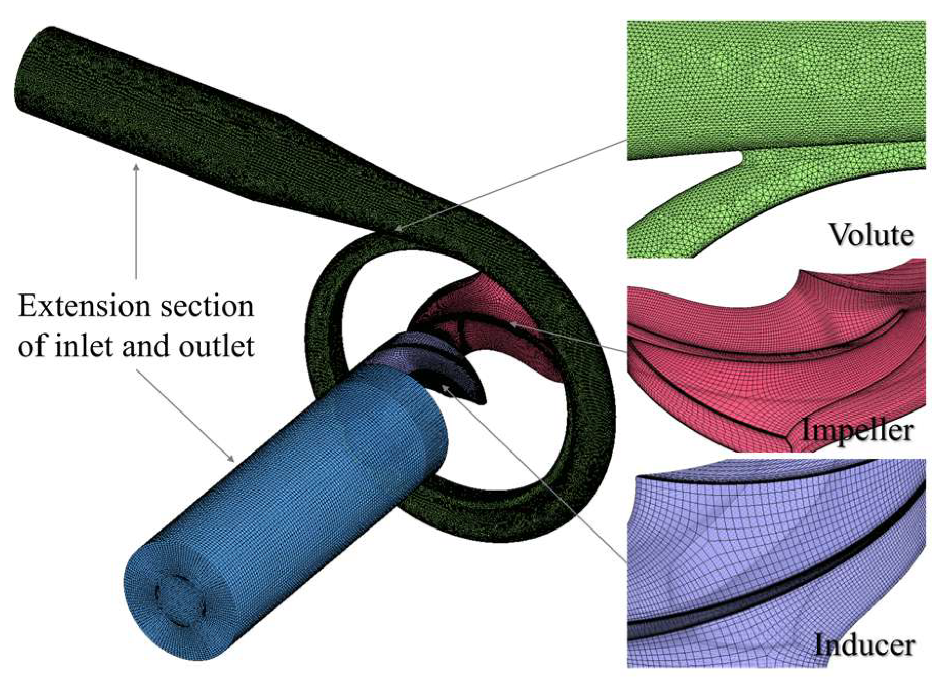
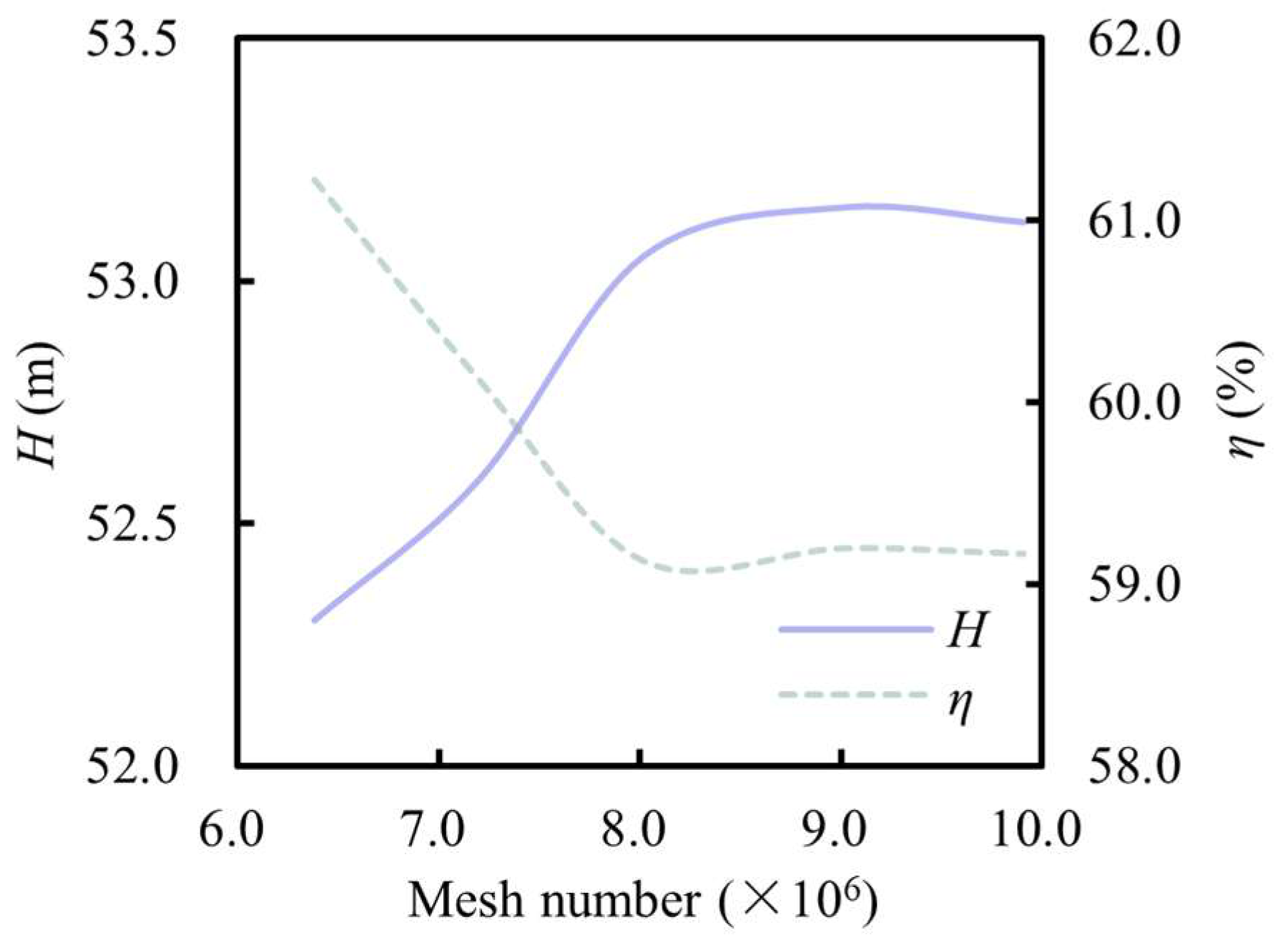
2.4. Mesh Independence

The accuracy and stability of numerical simulations are strongly influenced by the number of computational meshes. However, an excessively fine mesh may lead to unnecessary consumption of computational resources. Therefore, it is essential to determine an appropriate mesh density that balances computational efficiency and accuracy. A mesh independence study was conducted under the design operating condition, and the results are presented in Figure 3. When the mesh numbers were 6.38, 7.20, 8.02, 9.01, and 9.91 million, the corresponding head values were 52.3, 52.6, 53.0, 53.2, and 53.1 m, and the corresponding efficiencies were 61.2%, 60.1%, 59.1%, 59.2%, and 59.2%, respectively. Based on the results, it was found that a mesh model with approximately 8.45 million cells offers a good balance between prediction accuracy and computational cost, fulfilling the requirements for numerical simulation.

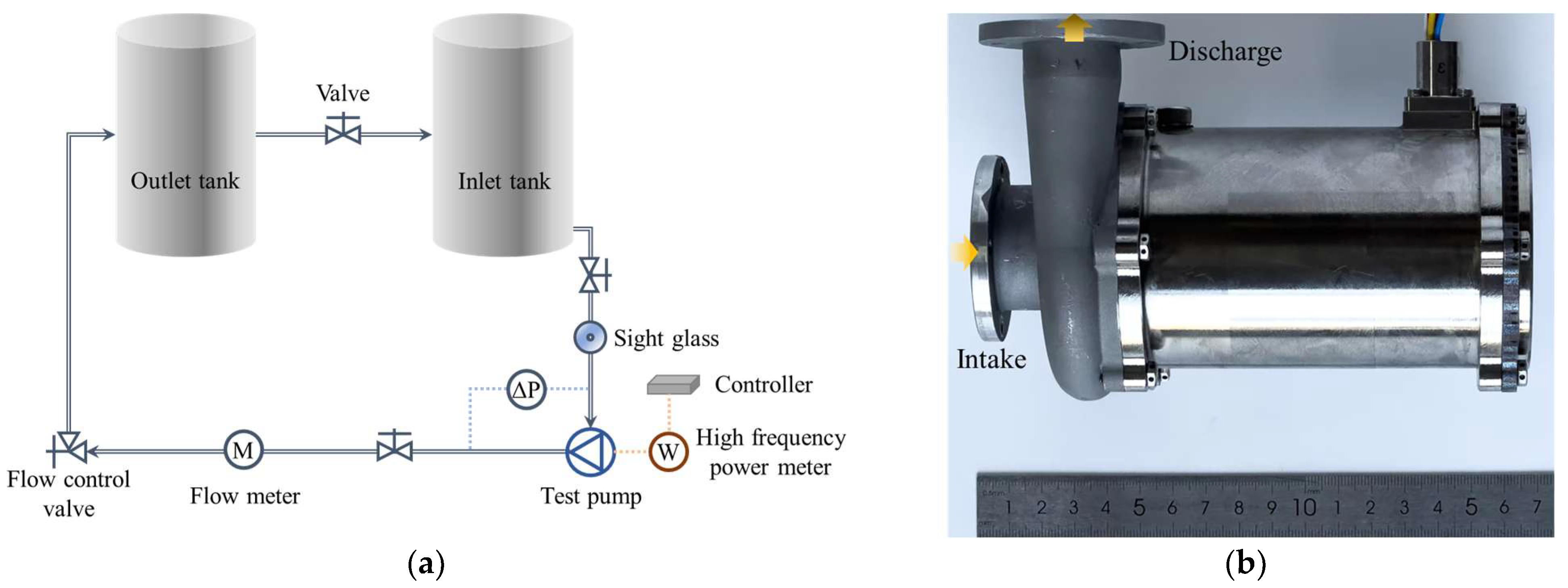
2.5. Experimental Validation

To validate the hydraulic performance predicted by the numerical model of the MHCP, a prototype pump was manufactured and evaluated experimentally using a closed-loop test system, as illustrated in Figure 4. The closed-loop system for hydraulic performance testing was established based on the pump test rig developed by Zhou of Xi’an Jiaotong University [20]. Two liquid storage tanks were used to provide a stable water supply for the pump prototype. The suction condition at the pump inlet could be visually inspected through a sight glass installed upstream of the pump. The flow rate in the loop was adjusted using a downstream needle valve and measured with a turbine flow meter, which has a measurement range of 0.6–6 m3/h and an accuracy of ±0.5%. The pump head was directly measured using a differential pressure sensor, with a measurement range of 0–1 MPa and an accuracy of ±0.5%. To simulate the electrical operating conditions of an UAV, the pump was powered at a rated voltage of 600 VDC. A digital power meter, with a measurement accuracy of ±0.1%, was used to directly measure the output power of the pump motor.
Figure 5 presents the performance curves of the MHCP under various operating conditions obtained from experimental measurements. As observed, the head-flow curves at different rotational speeds exhibit similar trends: with increasing flow rate, the head gradually decreases, and the rate of this decline becomes more pronounced—showing a gentle slope at low flow rates and a steeper drop at higher flow rates. For the efficiency-flow curves, the maximum efficiency decreases with decreasing rotational speed, and the corresponding flow rate at which the maximum efficiency occurs also shifts to lower values. At the design point, the pump delivers a head of 46.1 m and an efficiency of 49.7%, aligning with its BEP.
A comparison between experimental and numerical results indicates that the simulated head-flow curve closely matches the experimental data. However, as the rotational speed increases, the deviation in head also becomes more pronounced, with a maximum head deviation of 13.1%. Since the motor of the pump is integrated within the pump casing, direct measurement of motor losses is difficult. Therefore, the experimentally obtained efficiency includes both hydraulic and motor efficiency, whereas the numerical simulations focus on hydraulic performance and exclude motor efficiency. In addition, the numerical model also neglects leakage losses. As a result, the computed efficiency is higher than the experimental value. However, the overall trend and BEP location remain consistent. Overall, the developed numerical model demonstrates a strong capability in accurately predicting the hydraulic performance of the MHCP.

3. Optimization Method

This study introduces a novel method for optimizing the performance of an MHCP impeller by integrating CFD numerical simulation, response surface prediction modeling, and multi-objective optimization algorithms. The workflow of this optimization approach is illustrated in Figure 6. In this method, the key geometric parameters of the impeller are selected as input variables, while the impeller head Himp and efficiency ηimp are taken as the objective functions. The main parameters that significantly affect impeller performance are identified and optimized within a broad design range. Based on the internal flow characteristics of the impeller, the proposed method enables efficient and comprehensive optimization of its hydraulic performance [25,26], thereby improving the overall performance of the pump.

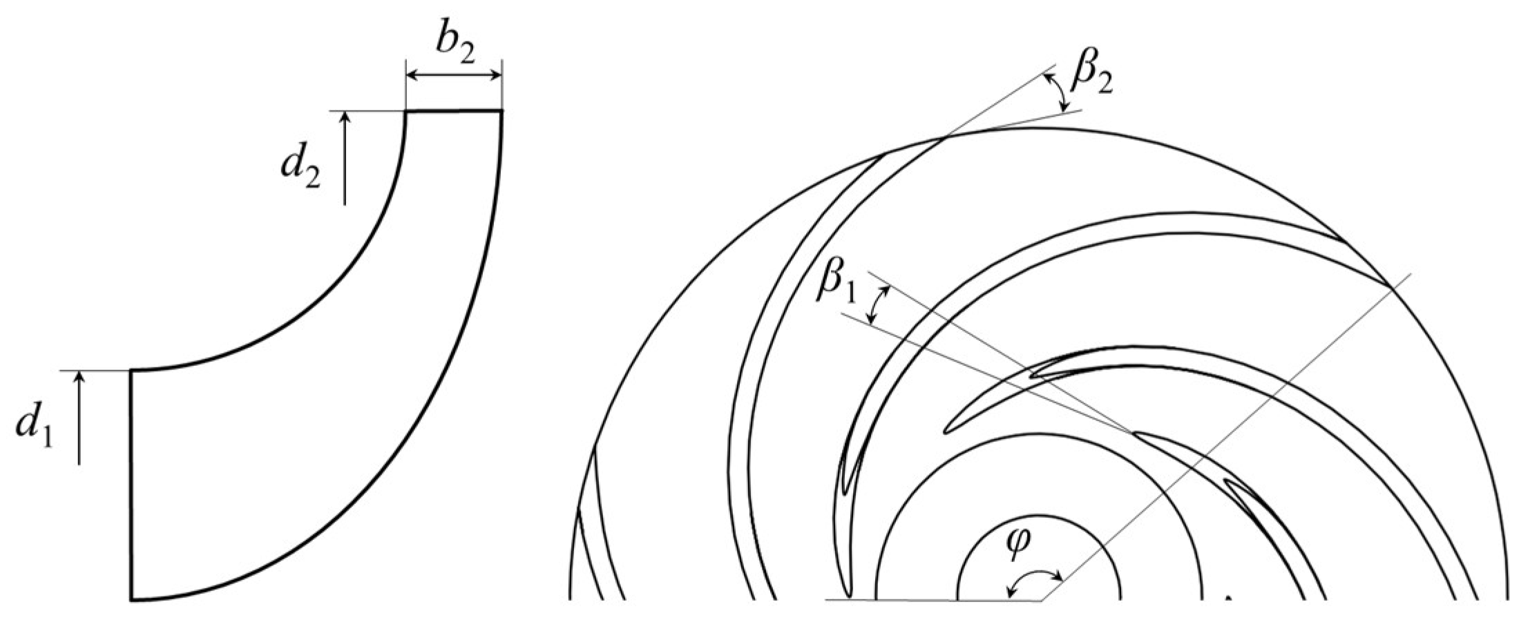
3.1. Optimization Variable

The subject of this study is a high-speed impeller composed of six blades, with its three-dimensional geometry generated using CFturbo 2023.2.3 software. During the optimization process, one blade was selected for parameter control and analysis, with its key geometric parameters illustrated in Figure 7. To ensure compatibility between the impeller and the upstream flow channel from the inducer, the influence of the impeller inlet diameter d1 is not considered in this study. Five geometric parameters were ultimately selected as design variables for the impeller optimization: blade inlet angle β1, blade outlet angle β2, outlet diameter d2, blade width b2, and wrap angle φ. The optimization variables and their respective ranges are summarized in Table 1.

3.2. Optimization Objectives and Sample Collection

To enhance the performance of the miniature centrifugal pump impeller under high-speed operating conditions, the design operating point was selected as the boundary condition for the initial impeller optimization model. The impeller head Himp and hydraulic efficiency ηimp were taken as constraint conditions, with the objective of maximizing the overall hydraulic performance of the pump. The mathematical expression of the objective function is given as follows:
H imp , opt H imp , ori
η imp , opt η imp , ori
A sample data acquisition workflow was established in this study. ANSYS Workbench 2022 R1, coupled with the optiSLang 2022 R1 module, was utilized to facilitate the steady-state numerical simulations for the impeller. CFturbo 2023.2.3, TurboGrid 2022 R1, Ansys Meshing 2022 R1, and CFX 2022 R1 were employed for model parameterization and numerical analysis. First, the optimization variables were extracted from the parameterized impeller model in CFturbo. During the optimization process, whenever control parameters were modified, structured grids for the computational domain were regenerated automatically using Turbogrid and Ansys Meshing. Subsequently, the generated meshes were transferred to CFX for automatic data linking and preprocessing setup, enabling the steady-state simulation of the impeller. The impeller head Himp and efficiency ηimp were set as output parameters in CFD-Post and exported to the parameter set in ANSYS Workbench.
Latin Hypercube Sampling (LHS) is a commonly used method for sampling in high-dimensional spaces [27]. It partitions the domain of each input variable into multiple intervals, ensuring that each interval includes at least one sample, which promotes uniform coverage across the entire input space and reduces sampling bias. In this study, during the execution of the optimization algorithm, the initial sample size was set to 156, with 16 new samples generated per iteration and a maximum of 10 iterations allowed. Based on the specified optimization parameters, an improved LHS method was used to generate 300 design points, which were then subjected to steady-state numerical simulations.

3.3. Surrogate Model

A sensitivity analysis of the output sample results was conducted to evaluate the influence of input parameters on the output responses. The Kriging method, a response surface model based on linear regression analysis, was utilized for this purpose [28]. Kriging fits the training data by considering the spatial correlation among input variables and can effectively capture complex nonlinear relationships between inputs and outputs. It enables the determination of the sensitivity of each input variable. The mathematical expression of the Kriging model is given as follows:
y ( x ) = f ( A , x ) + z ( x ) = A f T ( x ) + z ( x )
where A is regression coefficients; f(x) is a polynomial function of the random variable x, representing the response function; z(x) is a stochastic process with a mean of zero. The covariance matrix is defined as follows:
cov z x i , z x j = σ z 2 R θ , x i , x j
R θ , x i , x j = k = 1 n R k θ k , x i , k , x j , k
where σ z 2 represents the variance of the predicted value z(x); θ is the correlation coefficient used to control the rate at which the correlation between sample points decays with distance; R θ , x i , x j denotes the spatial correlation function between any two sample points xi and xj in the sample space, reflecting their statistical dependence.
The prediction coefficient is determined using the following formula:
R 2 = S R S T = 1 S E S T
S R = i = 1 N y ^ i μ Y ^ 2
S T = i = 1 N y ^ i μ Y 2
S E = i = 1 N y i y ^ i 2
In the equation, SR, ST, and SE represent the explained variation, total variation, and unexplained variation, respectively. The fitting error can be corrected as follows:
R a d j 2 = 1 N 1 N q 1 R 2
Figure 8 presents the residual plots of Himp and ηimp fitted using the Kriging surrogate model. As shown in the figure, the residuals are uniformly and randomly distributed, indicating good randomness. The surrogate model demonstrates excellent fitting performance for the two defined objective functions, with no significant bias or discernible trends observed. Therefore, the Kriging model accurately captures the true relationship between the input variables and the output responses. This validates the model generalization capability, making it suitable for optimization and prediction tasks.

4. Results and Discussion

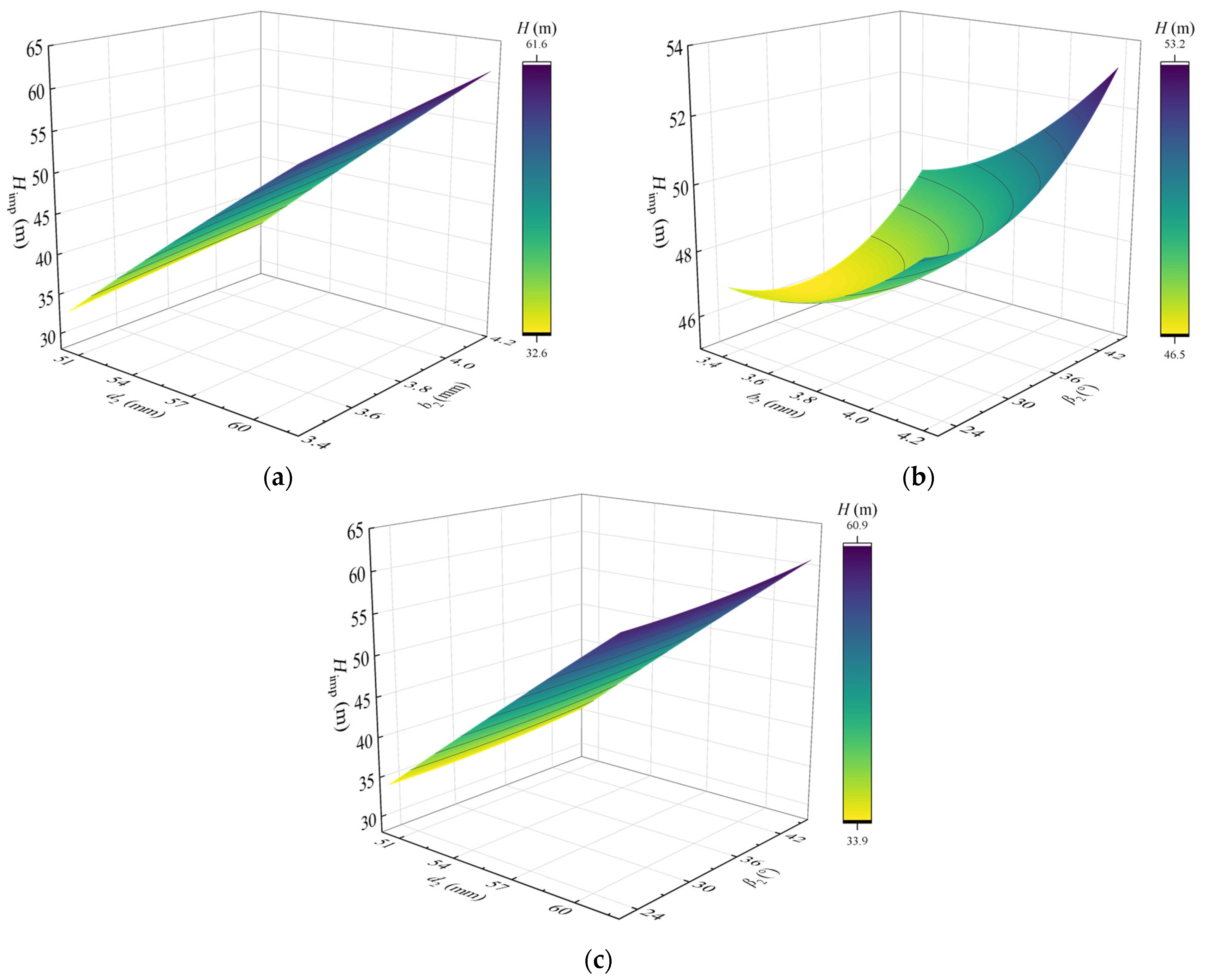
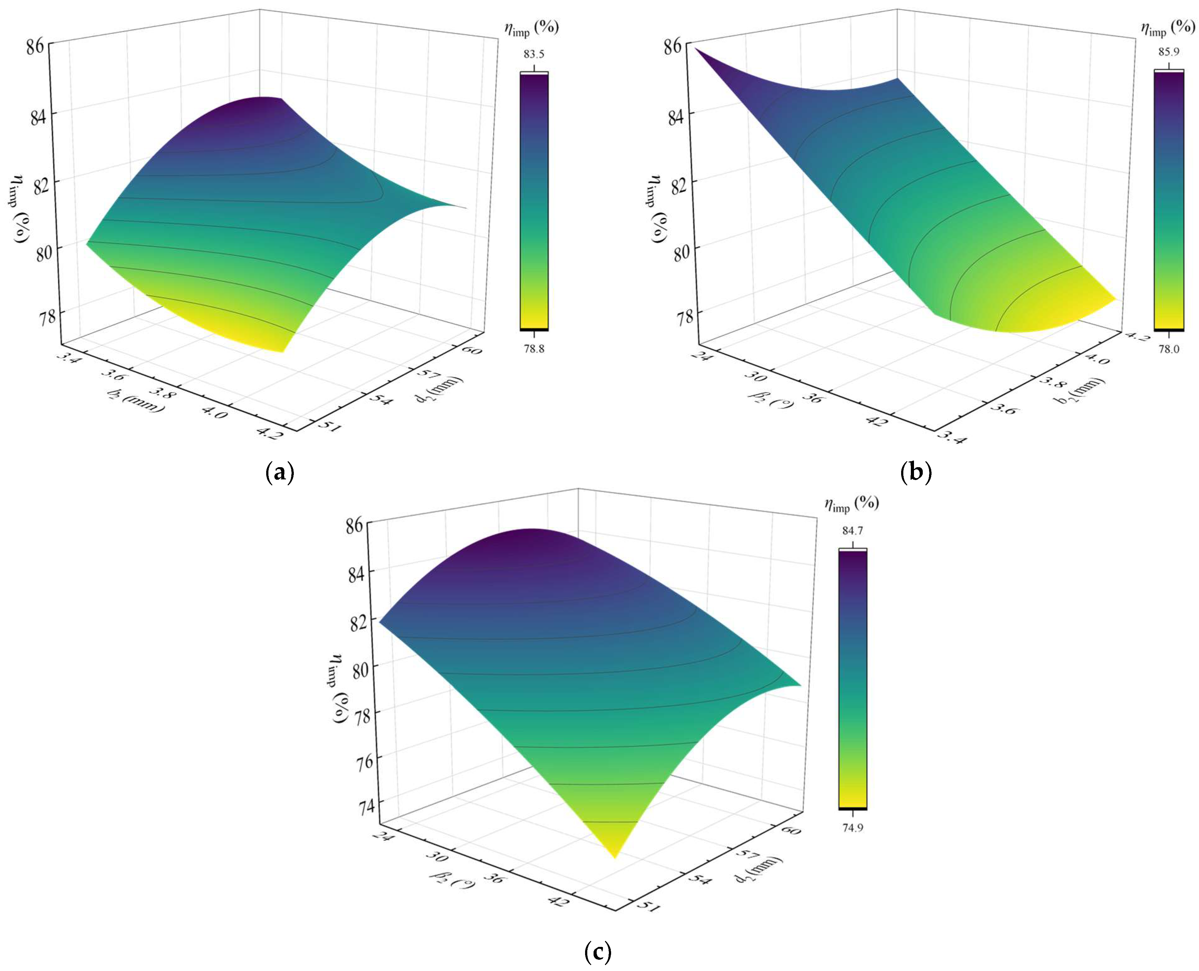
4.1. Response Surface Analysis of Optimization Variables

The impact of each variable parameters of the impeller on Himp and ηimp under the target response is shown in Figure 9. Sensitivity analysis of the varying parameters indicates that the selected impeller structural parameters have a more pronounced impact on the head than on the efficiency. Further analysis of the contribution ratio α of each optimized parameter to the target responses reveals that the impeller outlet diameter d2 has the greatest influence on the improvements in head and efficiency, respectively. These two parameters are thus identified as the dominant factors in impeller structure optimization for performance enhancement.
Figure 10 and Figure 11 illustrate the response surface models for the objective variables Himp and ηimp, respectively. Regarding the response surface of Himp, an increase in outlet diameter d2, blade width b2, and blade outlet angle β2 generally leads to a strong linear increase in head. However, there exists a noticeable nonlinear relationship between b2 and β2. Despite this, the response surface formed by b2 and β2 remains relatively flat, indicating that their individual influence on head is relatively minor. Among all variables, a larger outlet diameter is most beneficial for increasing head.
In contrast, the response surface of ηimp exhibits more pronounced nonlinear interactions among blade outlet angle β2, outlet diameter d2, and blade width b2. It can be observed from Figure 11 that increases in both blade width b2 and blade outlet angle β2 suppress impeller efficiency. Similarly, an increase in impeller outlet diameter also has a negative impact on pump efficiency to some extent.

4.2. Performance Optimization Results of MHCP

Table 2 presents a comparison of the structural parameters of the pump impeller before and after optimization based on response surface analysis. Compared with the original design, the optimized impeller shows increased blade inlet angle β1, outlet diameter d2, and wrap angle φ, which are favorable for enhancing the pump power capability. On the other hand, the blade outlet angle β2 and blade width b2 are reduced compared to the original impeller. As discussed previously, this adjustment likely aims to balance the improvement in hydraulic efficiency.
A numerical simulation using CFX was conducted to evaluate the performance of the MHCP with the optimized impeller. The steady-state results indicate improvements in both head and efficiency, with increases of 3.7 m and 4.8%, respectively.

4.3. Flow Characteristics of MHCP Under Design Condition

At the design operating condition, the flow field distributions at the mid-blade height inside the original and optimized impellers are shown in Figure 12, Figure 13 and Figure 14. Figure 12 illustrates the total pressure distribution inside the impeller. In the optimized impeller, modifications such as increased blade curvature and adjusted blade angles enhance both the outlet pressure and velocity of the impeller. These changes lead to intensified flow separation and reverse flow near the trailing edge, which in turn contribute to the formation of a localized high-pressure region on the suction side of the blade trailing edge. This contrasts with the original impeller, where a high-pressure region appears near the pressure side trailing edge. Moreover, in the optimized design, the extent of the low-pressure region is significantly reduced.
Figure 13 illustrates the velocity distribution inside the impeller fluid channels. In the original impeller, slight flow separation is observed near the blade wall under high-speed rotation, and the overall flow velocity within the impeller is lower. Additionally, due to the larger blade outlet angle, the fluid exiting the original impeller exhibits a higher velocity at the trailing edge.
Figure 14 depicts the turbulent kinetic energy distribution inside the impeller. The turbulence kinetic energy range is significantly reduced in the optimized impeller, indicating an improved internal flow. Furthermore, the optimized structural parameters help mitigate turbulence at the impeller outlet.

5. Conclusions

In this study, a numerical model of the MHCP was developed and validated through hydraulic performance tests conducted on a pump test rig. Based on the validated model, RSM was employed to optimize the impeller design and analyze the influence of various impeller parameters on pump performance. The main conclusions are as follows:
  • The hydraulic performance of the MHCP under different operating conditions was obtained experimentally, and the accuracy of the numerical model was validated, showing a maximum head deviation of less than 13.1%. At the design condition (speed = 10,000 rpm, flow rate = 4.8 m3/h), the MHCP reaches its BEP, with a corresponding head of 46.1 m and efficiency of 49.7%.
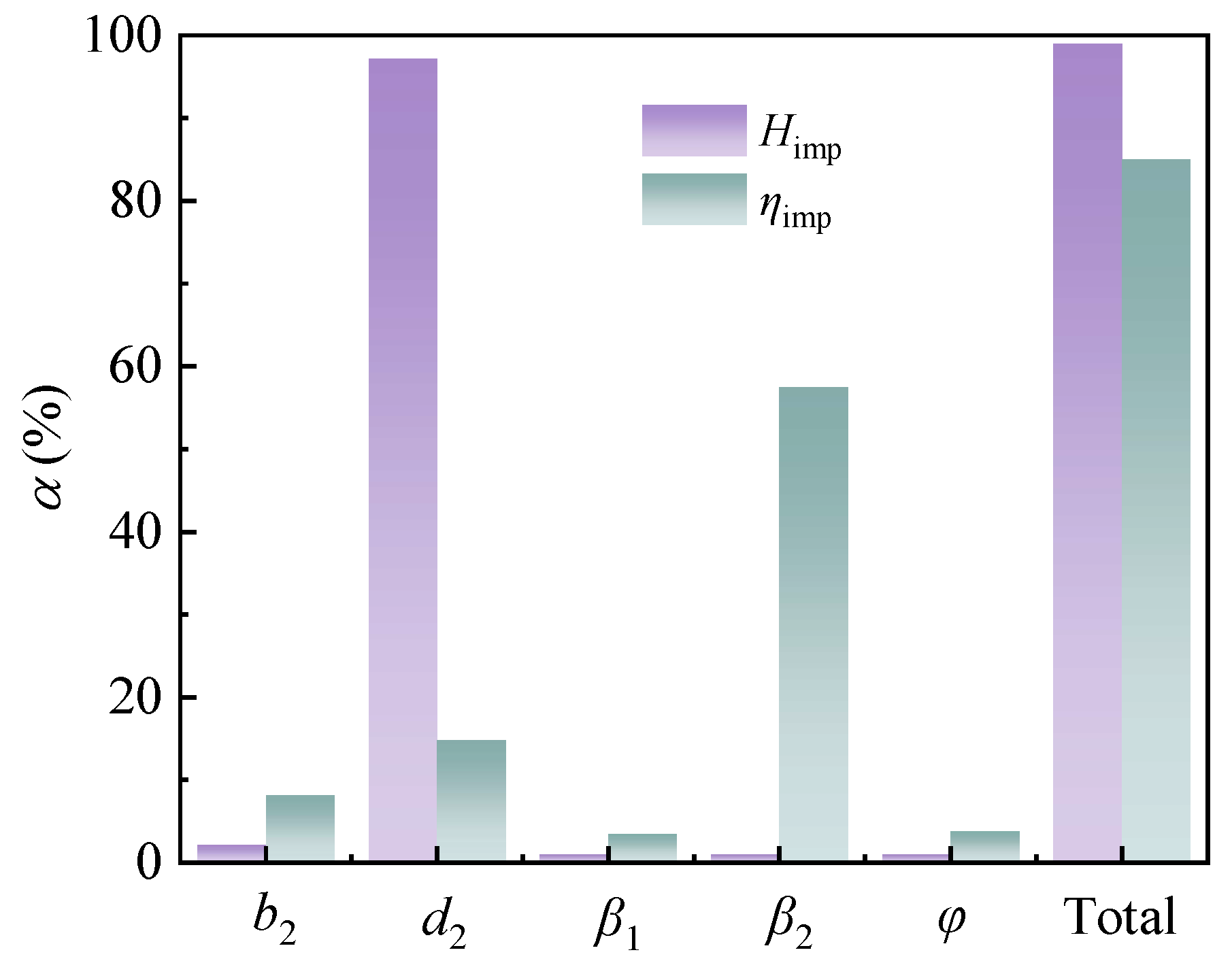
  • A Kriging-based response surface analysis was established, achieving reliable performance prediction for optimization. Sensitivity analysis revealed that the impeller outlet diameter d2 has the most significant influence on head, while the blade outlet angle β2 is the key factor affecting efficiency.
  • Within the defined design space, a multi-objective optimization targeting both impeller head Himp and efficiency ηimp was conducted. The optimized impeller achieved a Himp and ηimp improvement of 3.7 m and 4.8%, respectively, compared with the original design. Experimental validation of the MHCP equipped with the optimized impeller will be conducted in future work.
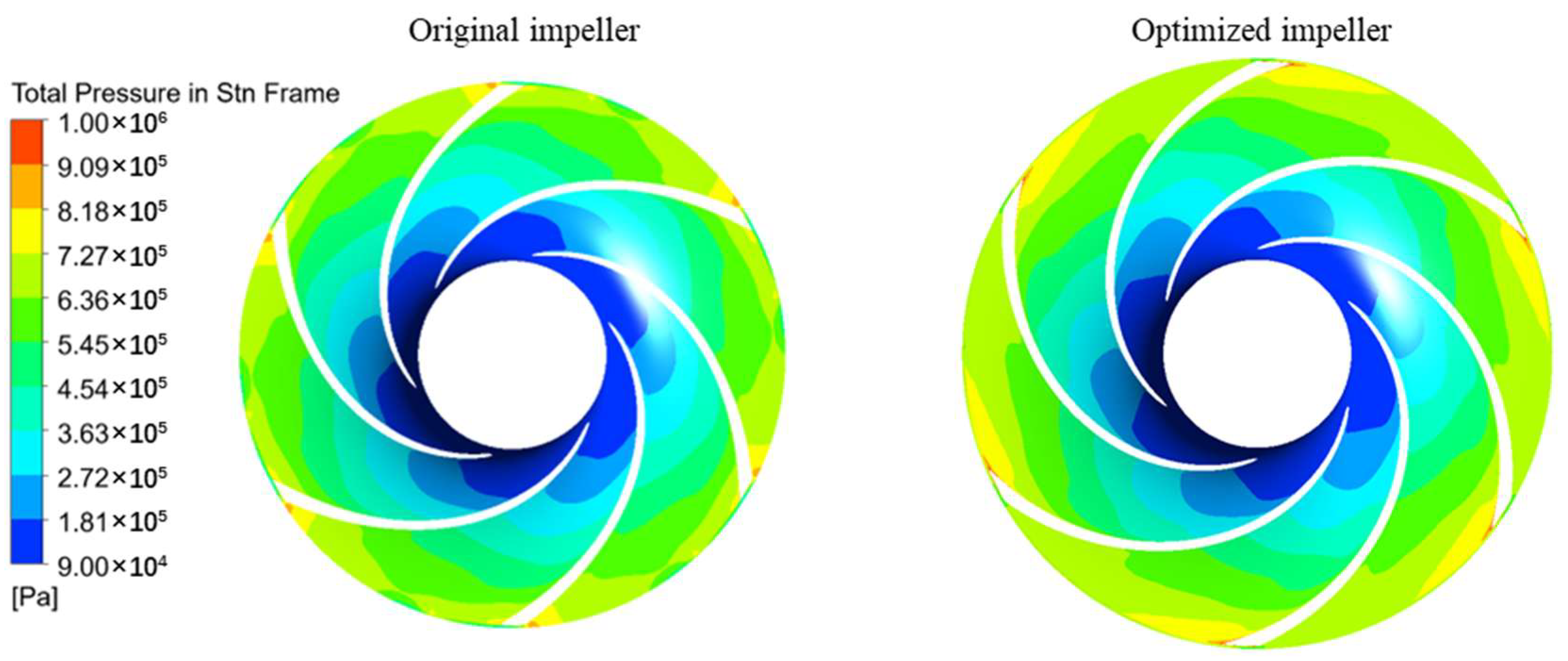
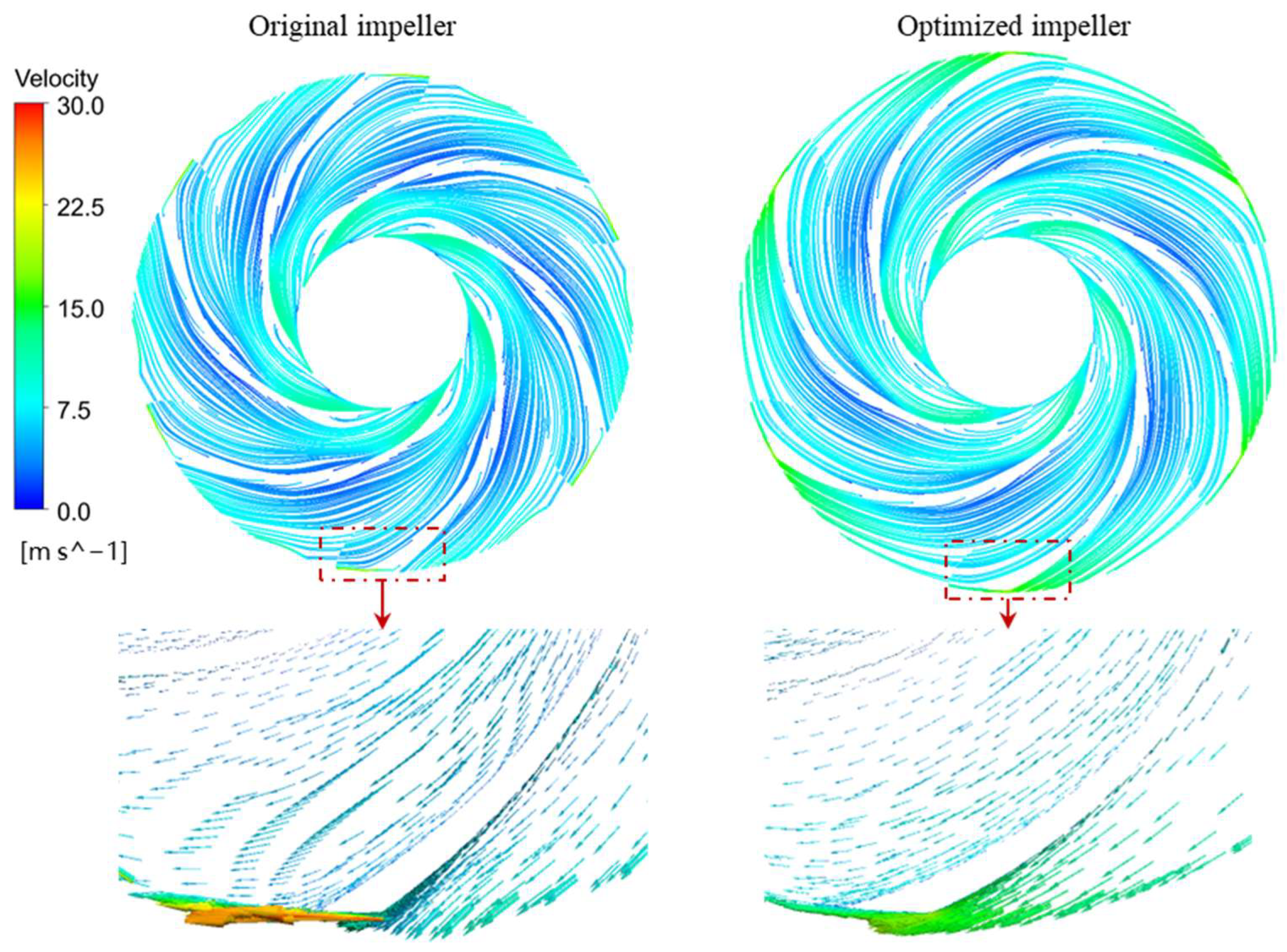
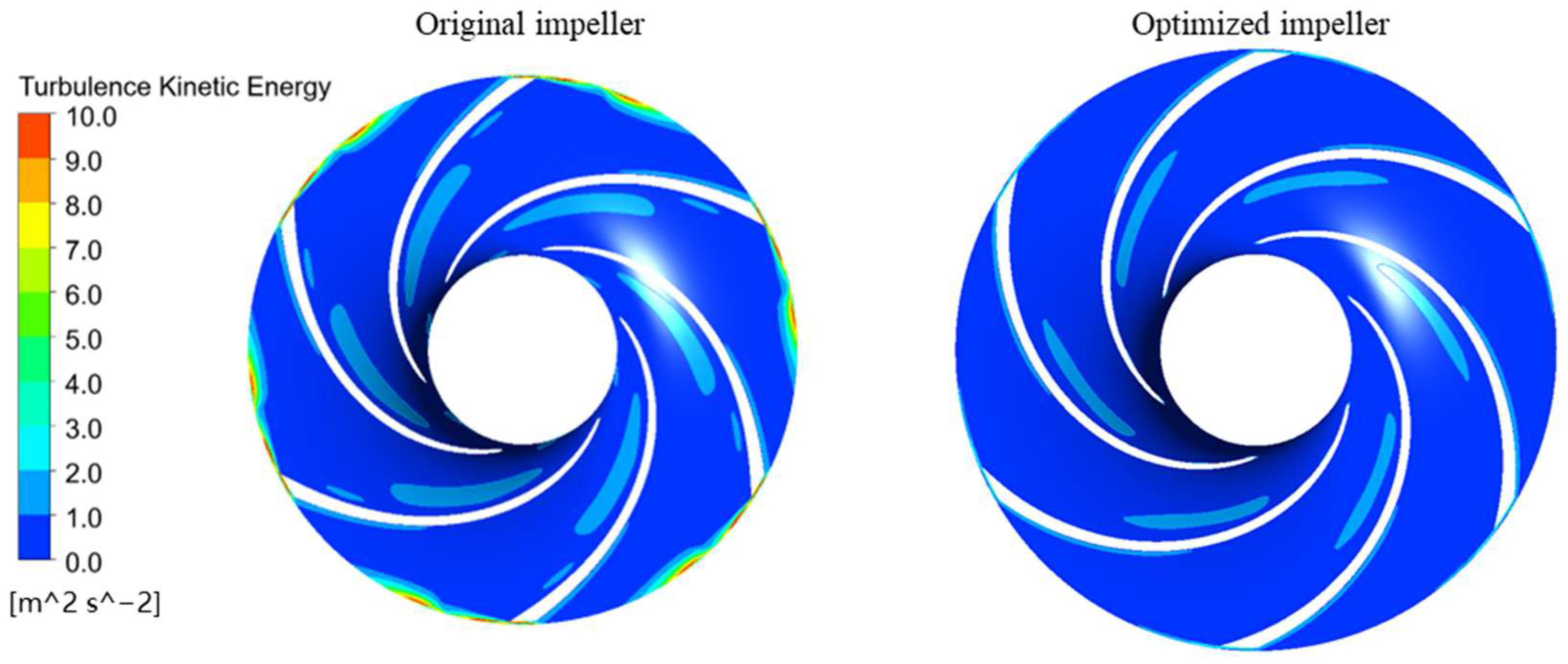
  • Flow field comparisons between the original and optimized impellers indicate that the optimized impeller exhibits a reduced low-pressure region and mitigated flow separation. Additionally, improvements were observed in turbulence kinetic energy near the suction surface and outlet of the blades.

Author Contributions

Methodology, Y.H.; Software, Y.H.; Formal analysis, Y.H.; Resources, R.X.; Writing—original draft, Y.H.; Writing—review & editing, Y.H. and R.X.; Supervision, R.X. All authors have read and agreed to the published version of the manuscript.

Funding

This research received no external funding.

Data Availability Statement

The original contributions presented in this study are included in the article. Further inquiries can be directed to the corresponding author.

Conflicts of Interest

The authors declare no conflicts of interest.

Abbreviations

The following abbreviations are used in this manuscript:
UAVunmanned aerial vehicle
MHCPminiature high-speed centrifugal pump
RSMresponse surface methodology
BEPbest efficiency point
PIVparticle image velocimetry
CFDComputational Fluid Dynamics
LHSLatin Hypercube Sampling

References

  1. Son, Y.W.; Kang, D.; Kim, J. Passive Battery Thermal Management System for an Unmanned Aerial Vehicle Using a Tetrahedral Lattice Porous Plate. Appl. Therm. Eng. 2023, 225, 120186. [Google Scholar] [CrossRef]
  2. Lei, T.; Yang, Z.; Lin, Z.; Zhang, X. State of Art on Energy Management Strategy for Hybrid-Powered Unmanned Aerial Vehicle. Chin. J. Aeronaut. 2019, 32, 1488–1503. [Google Scholar] [CrossRef]
  3. Wang, S.; Wang, H.; Chang, M.; Xu, J.; Wang, J.; Yang, X.; Bai, J. A Novel Battery Thermal Management System for an Unmanned Aerial Vehicle Using the Graphene Directional Heat Transfer Structure. J. Power Sources 2023, 588, 233726. [Google Scholar] [CrossRef]
  4. Sakanova, A.; Tong, C.F.; Nawawi, A.; Simanjorang, R.; Tseng, K.J.; Gupta, A.K. Investigation on Weight Consideration of Liquid Coolant System for Power Electronics Converter in Future Aircraft. Appl. Therm. Eng. 2016, 104, 603–615. [Google Scholar] [CrossRef]
  5. Wu, C.; Pu, K.; Li, C.; Wu, P.; Huang, B.; Wu, D. Blade Redesign Based on Secondary Flow Suppression to Improve Energy Efficiency of a Centrifugal Pump. Energy 2022, 246, 123394. [Google Scholar] [CrossRef]
  6. Liu, X.; Farhat, M.; Li, Y.; Liu, Z.; Yang, W. Onset of Flow Separation Phenomenon in a Low-Specific Speed Centrifugal Pump Impeller. J. Fluids Eng. 2023, 145, 021206. [Google Scholar] [CrossRef]
  7. Fang, X.; Zhang, B.; Lin, X.; Zhou, H.; Chen, S.; Hou, Y.; Xue, R.; Zhang, Z. Numerical and Experimental Investigation of Flow Characteristics in a Fluid Self-Lubricating Centrifugal Pump with R134a Refrigerant. Appl. Sci. 2023, 13, 8062. [Google Scholar] [CrossRef]
  8. Kye, B.; Park, K.; Choi, H.; Lee, M.; Kim, J.-H. Flow Characteristics in a Volute-Type Centrifugal Pump Using Large Eddy Simulation. Int. J. Heat Fluid Flow 2018, 72, 52–60. [Google Scholar] [CrossRef]
  9. Lin, X.; Zhang, B.; Zhang, M.; Zhao, Y.; Lai, T.; Chen, L.; Xue, R. Influence of Internal Flow on the Performance of High-Speed Centrifugal Pumps with a Fully Sealed Structure. Appl. Sci. 2022, 12, 5263. [Google Scholar] [CrossRef]
  10. Wang, X.; Wang, Y.; Liu, H.; Xiao, Y.; Jiang, L.; Li, M. A Numerical Investigation on Energy Characteristics of Centrifugal Pump for Cavitation Flow Using Entropy Production Theory. Int. J. Heat Mass Transf. 2023, 201, 123591. [Google Scholar] [CrossRef]
  11. Xue, R.; Lin, X.; Zhang, B.; Zhou, H.; Lai, T.; Hou, Y. CFD and Energy Loss Model Analysis of High-Speed Centrifugal Pump with Low Specific Speed. Appl. Sci. 2022, 12, 7435. [Google Scholar] [CrossRef]
  12. Zhang, Z.; Chen, H.; Yin, J.; Ma, Z.; Gu, Q.; Lu, J.; Liu, H. Unsteady Flow Characteristics in Centrifugal Pump Based on Proper Orthogonal Decomposition Method. Phys. Fluids 2021, 33, 075122. [Google Scholar] [CrossRef]
  13. Fu, Y.; Yuan, J.; Yuan, S.; Pace, G.; d’Agostino, L.; Huang, P.; Li, X. Numerical and Experimental Analysis of Flow Phenomena in a Centrifugal Pump Operating Under Low Flow Rates. J. Fluids Eng. 2014, 137, 011102. [Google Scholar] [CrossRef]
  14. Li, X.; Chen, B.; Luo, X.; Zhu, Z. Effects of Flow Pattern on Hydraulic Performance and Energy Conversion Characterisation in a Centrifugal Pump. Renew. Energy 2020, 151, 475–487. [Google Scholar] [CrossRef]
  15. Zhang, N.; Gao, B.; Li, Z.; Ni, D.; Jiang, Q. Unsteady Flow Structure and Its Evolution in a Low Specific Speed Centrifugal Pump Measured by PIV. Exp. Therm. Fluid Sci. 2018, 97, 133–144. [Google Scholar] [CrossRef]
  16. Zhang, J.; Yang, H.; Liu, H.; Xu, L.; Lv, Y. Pressure Fluctuation Characteristics of High-Speed Centrifugal Pump with Enlarged Flow Design. Processes 2021, 9, 2261. [Google Scholar] [CrossRef]
  17. Ding, H.; Li, Z.; Gong, X.; Li, M. The Influence of Blade Outlet Angle on the Performance of Centrifugal Pump with High Specific Speed. Vacuum 2019, 159, 239–246. [Google Scholar] [CrossRef]
  18. Yan, S.; Ye, Z.; Wang, D.; Ma, J.; Zhou, W. Structural Analysis and Optimization of Ultra-High-Speed Centrifugal Pump Rotor System Considering Fluid–Structure Interaction. Water 2024, 16, 1471. [Google Scholar] [CrossRef]
  19. Cui, B.; Liu, J.; Zhai, L.; Han, A. Analysis of the Performance and Pressure Pulsation in a High-Speed Centrifugal Pump with Different Hub-Cutting Angles. Mod. Phys. Lett. B 2023, 37, 2350117. [Google Scholar] [CrossRef]
  20. Zhou, H.; Xue, R.; Liang, Y.; Niu, B.; Chen, S.; Hou, Y. Tip Clearance Influence on the Performance of High-Speed Micro-Pumps. Phys. Fluids 2024, 36, 115129. [Google Scholar] [CrossRef]
  21. Medvitz, R.B.; Kunz, R.F.; Boger, D.A.; Lindau, J.W.; Yocum, A.M.; Pauley, L.L. Performance Analysis of Cavitating Flow in Centrifugal Pumps Using Multiphase CFD. J. Fluids Eng. 2002, 124, 377–383. [Google Scholar] [CrossRef]
  22. Yun, R.; Zuchao, Z.; Denghao, W.; Xiaojun, L. Influence of Guide Ring on Energy Loss in a Multistage Centrifugal Pump. J. Fluids Eng. 2018, 141, 061302. [Google Scholar] [CrossRef]
  23. Wei, A.; Wang, W.; Hu, Y.; Feng, S.; Qiu, L.; Zhang, X. Numerical and Experimental Analysis of the Cavitation and Flow Characteristics in Liquid Nitrogen Submersible Pump. Phys. Fluids 2024, 36, 042109. [Google Scholar] [CrossRef]
  24. Menter, F.R. Two-Equation Eddy-Viscosity Turbulence Models for Engineering Applications. AIAA J. 1994, 32, 1598–1605. [Google Scholar] [CrossRef]
  25. Wang, W.; Sun, J.; Liu, J.; Zhao, J.; Pei, J.; Wang, J. Introducing Non-Hierarchical RSM and MIGA for Performance Prediction and Optimization of a Centrifugal Pump under the Nominal Condition. Processes 2022, 10, 1529. [Google Scholar] [CrossRef]
  26. Wang, W.; Pei, J.; Yuan, S.; Zhang, J.; Yuan, J.; Xu, C. Application of Different Surrogate Models on the Optimization of Centrifugal Pump. J. Mech. Sci. Technol. 2016, 30, 567–574. [Google Scholar] [CrossRef]
  27. Stein, M. Large Sample Properties of Simulations Using Latin Hypercube Sampling. Technometrics 1987, 29, 143–151. [Google Scholar] [CrossRef]
  28. Kaymaz, I. Application of Kriging Method to Structural Reliability Problems. Struct. Saf. 2005, 27, 133–151. [Google Scholar] [CrossRef]
Figure 1. The original pump model.
Fluids 10 00174 g001
Figure 2. Computational domain and mesh.
Fluids 10 00174 g002
Figure 3. The mesh independence analysis.
Fluids 10 00174 g003
Figure 4. Schematic of test system and test pump. (a) Sketch of the test rig; (b) Prototype of the tested pump.
Fluids 10 00174 g004
Figure 5. Hydraulic performance curve of the MHCP. (a) H-Q; (b) η-Q.
Fluids 10 00174 g005
Figure 6. Flow chart of optimization process.
Fluids 10 00174 g006
Figure 7. Geometric parameters of the impeller.
Fluids 10 00174 g007
Figure 8. Residual plot of predicted value and sample data. (a) Head; (b) Efficiency.
Fluids 10 00174 g008
Figure 9. Significant variable parameters affecting pump performance.
Fluids 10 00174 g009
Figure 10. Response surface model of target variable Himp. (a) d2 and b2; (b) b2 and β2; (c) d2 and β2.
Fluids 10 00174 g010
Figure 11. Response surface model of target variable ηimp. (a) d2 and b2; (b) b2 and β2; (c) d2 and β2.
Fluids 10 00174 g011
Figure 12. The pressure distribution of original and optimized impeller (span = 0.5).
Fluids 10 00174 g012
Figure 13. The velocity distribution of original and optimized impeller (span = 0.5).
Fluids 10 00174 g013
Figure 14. The turbulence kinetic energy distribution of original and optimized impeller (span = 0.5).
Fluids 10 00174 g014
Table 1. Optimization variables of impeller.
ParametersOriginal ValueRange
Blade inlet angle β1 (°)83–13
Blade outlet angle β2 (°)3421–46
Outlet diameter d2 (mm)5650–62
Blade width b2 (mm)3.83.3–4.2
Wrap angle φ (°)150135–165
Table 2. Optimized impeller structure parameters and pump performance.
ParmetersOriginal ImpellerOptimized Impeller
Blade inlet angle β1 (°)88.6
Blade outlet angle β2 (°)3422
Outlet diameter d2 (mm)5660.7
Blade width b2 (mm)3.83.4
Wrap angle φ (°)150153.3
Himp (m)53.156.8
ηimp (%)80.385.1
Disclaimer/Publisher’s Note: The statements, opinions and data contained in all publications are solely those of the individual author(s) and contributor(s) and not of MDPI and/or the editor(s). MDPI and/or the editor(s) disclaim responsibility for any injury to people or property resulting from any ideas, methods, instructions or products referred to in the content.

