Article

Slow Translation and Rotation of a Composite Sphere Parallel to One or Two Planar Walls

Department of Chemical Engineering, National Taiwan University, Taipei 10617, Taiwan
*
Author to whom correspondence should be addressed.
Fluids 2025, 10(6), 154; https://doi.org/10.3390/fluids10060154
Submission received: 14 May 2025 / Revised: 9 June 2025 / Accepted: 10 June 2025 / Published: 12 June 2025
(This article belongs to the Section Flow of Multi-Phase Fluids and Granular Materials)

Abstract

A semi-analytical investigation is conducted to examine the coupled translational and rotational motions of a composite spherical particle (consisting of an impermeable hard core surrounded by a permeable porous shell) immersed in a viscous fluid parallel to one or two planar boundaries under the steady condition of a low Reynolds number. The fluid flow is described using the Stokes equations outside the porous shell and the Brinkman equation within it. A general solution is formulated by employing fundamental solutions in both spherical and Cartesian coordinate systems. The boundary conditions on the planar walls are implemented using the Fourier transform method, while those on the inner and outer boundaries of the porous shell are applied via a collocation technique. Numerical calculations yield hydrodynamic force and torque results with good convergence across a broad range of physical parameters. For validation, the results corresponding to an impermeable hard sphere parallel to one or two planar walls are shown to be in close agreement with established solutions from the literature. The hydrodynamic drag force and torque experienced by the composite particle increase steadily with larger values of the ratio of the particle radius to the porous shell’s permeation length, the ratio of the core radius to the total particle radius, and the separations between the particle and the walls. It has been observed that the influence of the walls on translational motion is significantly stronger than that on rotational motion. When comparing motions parallel versus normal to the walls, the planar boundaries impose weaker hydrodynamic forces but stronger torques during parallel motions. The coupling between the translation and rotation of the composite sphere parallel to the walls exhibits complex behavior that does not vary monotonically with changes in system parameters.

1. Introduction

The motion of small particles in viscous fluids, including their translation and rotation at low Reynolds numbers, continues to attract significant attention from researchers in various scientific, technological, and engineering domains. These fundamental processes provide a deep understanding of many practical systems, such as sedimentation, centrifugation, coagulation, filtration, aerosol technologies, suspension rheology, microfluidics, electrophoresis, and other phoretic movements. Stokes was the first to analyze the creeping motions of a hard, impermeable sphere in an unbounded Newtonian fluid [1,2], and these works were later expanded to cover the translation and rotation of a composite sphere [3,4].
A composite sphere with radius b consists of a hard sphere core with radius a , which is surrounded by a permeable porous layer with a thickness of b a . Typical examples of composite particles include biological cells with rough surface structures, ranging from micrometer-sized cilia to nanometer-sized protein molecules [5], as well as polystyrene latex particles with a porous surface extending into the surrounding fluid [6]. Colloidal suspension particles can be sterically stabilized against aggregation by purposely adsorbing polymers and forming porous surface layers [7].
When a composite particle with a radius, b , and a hard core with a radius, a , translates with the velocity, U , and rotates with the angular velocity, Ω , in an unbounded fluid of viscosity, η , the hydrodynamic force and torque acting on the particle are [3,4]
F 0 = 6 π η λ 1 { W λ a cosh λ a 3 λ 2 a 2 ( V + λ a sinh λ a ) + [ ( λ a V λ b cosh λ a ) W + 3 λ 3 a 2 b sinh λ a ] G 1 + [ W cosh λ a + 3 λ 2 a 2 ( λ a V sinh λ a ) ] G 2 } × { ( λ a sinh λ b cosh λ a ) [ ( W + 3 λ b ) G 1 + 3 ( λ 2 a 2 1 ) G 2 6 λ a ] } 1 U ,
T 0 = 8 π η b 3 [ 1 + 3 λ 2 b 2 3 ( G 1 + λ a G 2 ) λ b ( G 2 + λ a G 1 ) ] Ω ,
where
G 1 = cosh ( λ b λ a ) ,         G 2 = sinh ( λ b λ a ) ,
V = λ b sinh λ b cosh λ b ,         W = 2 λ 3 b 3 + λ 3 a 3 + 3 λ a ,
and λ 1 is the square root of the fluid permeability or flow penetration length within the porous surface layer of the particle. The drag force and torque exerted on the particle are proportional to the translational and angular velocities, respectively. Note that the translation and rotation are uncoupled in the case of an unconfined composite sphere; i.e., F 0 and T 0 are independent of Ω and U , respectively. In limiting cases in which a = b and a = 0 , Equations (1) and (2) reduce to the Stokes results ( F 0 = 6 π η b U and T 0 = 8 π η b 3 Ω ) for a hard sphere and equivalent results for a completely porous (permeable) sphere [4,8], respectively, of radius b . Within the limits λ b = 0 and λ b , these equations simplify to the Stokes results for a hard sphere with radii a and b , respectively. In fact, ( λ b ) 2 is known as the Darcy number.
In real-world scenarios, particles are not isolated, and the surrounding fluid is constrained by solid boundaries [9,10,11]. Therefore, it is crucial to determine whether the proximity of a boundary significantly influences the motion of the particles. Past research has extensively analyzed the low-Reynolds number translation and rotation of a hard sphere near various types of boundaries [12,13,14,15,16,17,18,19,20,21]. Additionally, studies have also investigated the slow translation and rotation of a composite sphere inside a concentric [4,22,23] or non-concentric [24,25,26] spherical cavity, within a circular cylinder [27], and perpendicular to one or two planar walls [28,29]. These studies demonstrate that boundary effects on the motion of both hard and composite particles can be significant and intriguing.
In practical applications, we often encounter translations and rotations of a composite sphere near one or two planar walls, but not perpendicular to the walls. The aim of this article is to derive a semi-analytical solution for the slow translation and rotation of a composite sphere parallel to one or two planar walls. These parallel motions present more complex challenges because they break the azimuthal symmetry, causing the translation and rotation to become coupled. By combining analytical and numerical techniques, the Stokes and Brinkman equations governing the external and internal fluid flows, respectively, with respect to the porous layer, are solved using a boundary collocation approach. The wall-corrected drag force and torque exerted by the fluid on the composite particle are then determined, with the solutions showing good convergence. Since the problem of the slow translation and rotation of a composite sphere in arbitrary directions near one or two large planar walls is linear, the solutions can be obtained by superimposing the solutions to two subproblems: motions normal to the planar walls, which have been previously studied [28,29], and motions parallel to the planar walls, which are addressed in this work.

2. Analysis

As shown in Figure 1, we consider the steady motion of a viscous fluid caused by a composite particle with radius b consisting of a hard sphere core with radius a and a porous surface layer with a thickness of b a , translating with the velocity, U = U e x , and rotating with the angular velocity, Ω = Ω e y , parallel to two large stationary planar walls (both normal to e z ) at distances c and d from the center of the composite sphere. Here, ( x , y , z ) , ( ρ , φ , z ) , and ( r , θ , φ ) represent the Cartesian, cylindrical, and spherical coordinate systems, respectively, originating from the particle center, e x , e y , and e z are the principal unit vectors in the Cartesian coordinates, and e r , e θ , and e ϕ are the principal unit vectors in the spherical coordinates. We set d c throughout the article without loss of generality. The fluid is at rest away from the composite sphere and on the nonslip planar walls. Our aim is to determine the modification of Equations (1) and (2) for the translational and rotational motions of a composite sphere due to the presence of the planar walls.
For the creeping flow of an incompressible Newtonian fluid, the fluid velocity, v , and pressure, p , outside the composite sphere are governed by the Stokes equations, as follows:
η 2 v p = 0 ,               v = 0               ( r b ) ,
where η is the fluid viscosity. Within the porous surface layer, the Brinkman and continuity equations,
η 2 v ^ p ^ η λ 2 ( v ^ U Ω × r ) = 0 ,               v ^ = 0               ( a r b ) ,
are used to govern the fluid velocity, v ^ , and pressure, p ^ , where the effective viscosity of the fluid is assumed to equal the viscosity of the bulk fluid [3,28,30], λ 2 is the reciprocal of permeability, and r = r e r is the position vector.
The boundary conditions for the external and internal fluid flows are
r = a :                     v ^ = U + a Ω × e r ,
r = b :       v = v ^ ,
e r ( τ p I ) = e r ( τ ^ p ^ I ) ,
z = c , d :       v = 0 ,
ρ :       v = 0 ,
where τ and τ ^ are viscous stress tensors for the external and internal flows, respectively, and I is the unit tensor. It can be shown that the boundary condition in Equation (8b), which represents the continuity of the total stress on the outer surface of the porous layer, is equivalent to
r = b :                     p = p ^ ,       v θ r = v ^ θ r ,       v ϕ r = v ^ ϕ r ,
where ( v θ , v ^ θ ) and ( v ϕ , v ^ ϕ ) are θ and ϕ components of the relevant fluid velocities, respectively.
A general solution of the external fluid velocity that satisfies Equations (5), (9), and (10) is
v = v x e x + v y e y + v z e z ,
where
v x = n = 1 [ A n ( A n + α n ) + B n ( B n + β n ) + C n ( C n + γ n ) ] ,
v y = n = 1 [ A n ( A n + α n ) + B n ( B n + β n ) + C n ( C n + γ n ) ] ,
v z = n = 1 [ A n ( A n + α n ) + B n ( B n + β n ) + C n ( C n + γ n ) ] ,
the primed A n , B n , C n , α n , β n , and γ n are functions of position defined by Equations (2.6) and (C1) of Ganatos et al. [13], and A n , B n , and C n are unknown constants. The corresponding solution for the fluid pressure can be obtained by integrating Equation (5) with the following result:
p = η n = 1 [ A n A n + B n B n + C n C n ] ,
where A n , B n , and C n are functions of position, which are lengthy and defined by Equations (A10)–(A12) in Appendix A. All numerical integrations used to evaluate the primed A n , B n , C n , α n , β n , and γ n functions are performed using the Gauss–Laguerre quadrature method.
The general solution of the internal fluid velocity satisfying Equation (6) can be obtained as
v ^ = v ^ r e r + v ^ θ e θ + v ^ ϕ e ϕ ,
where
v ^ r = [ n = 1 n ( n + 1 ) P n 1 ( μ ) { C ^ 1 n r n 1 + C ^ 2 n r n 2 + r 3 / 2 [ C ^ 3 n I n + 1 / 2 ( λ r ) + C ^ 4 n K n + 1 / 2 ( λ r ) ] } + U ( 1 μ 2 ) 1 / 2 ] cos ϕ ,
v ^ θ = [ n = 1 { [ C ^ 1 n ( n + 1 ) r n 1 + n C ^ 2 n r n 2 + C ^ 3 n { n r 3 / 2 I n + 1 / 2 ( λ r ) λ r 1 / 2 I n 1 / 2 ( λ r ) } + C ^ 4 n { n r 3 / 2 K n + 1 / 2 ( λ r ) + λ r 1 / 2 K n 1 / 2 ( λ r ) } ] ( 1 μ 2 ) 1 / 2 d P n 1 ( μ ) d μ + r 1 / 2 [ D ^ 1 n I n + 1 / 2 ( λ r ) + D ^ 2 n K n + 1 / 2 ( λ r ) ] ( 1 μ 2 ) 1 / 2 P n 1 ( μ ) } + U μ + Ω r ] cos ϕ ,
v ^ ϕ = [ n = 1 { [ C ^ 1 n ( n + 1 ) r n 1 + n C ^ 2 n r n 2 + C ^ 3 n { n r 3 / 2 I n + 1 / 2 ( λ r ) λ r 1 / 2 I n 1 / 2 ( λ r ) } + C ^ 4 n { n r 3 / 2 K n + 1 / 2 ( λ r ) + λ r 1 / 2 K n 1 / 2 ( λ r ) } ] ( 1 μ 2 ) 1 / 2 P n 1 ( μ ) + r 1 / 2 [ D ^ 1 n I n + 1 / 2 ( λ r ) + D ^ 2 n K n + 1 / 2 ( λ r ) ] ( 1 μ 2 ) 1 / 2 d P n 1 ( μ ) d μ } U Ω r μ ] sin ϕ ,
μ = cos θ , I n and K n are the modified Bessel function of the first and second kinds of order n, respectively, P n 1 is the associated Legendre function of order n and degree one, and C ^ 1 n , C ^ 2 n , C ^ 3 n , C ^ 4 n , D ^ 1 n , and D ^ 2 n are unknown constants. Similar to the derivation of the external fluid pressure, the integration of Equation (6) yields the internal fluid pressure as follows:
p ^ = η λ 2 cos ϕ n = 1 [ ( n + 1 ) C ^ 1 n r n n C ^ 2 n r n 1 ] P n 1 ( μ ) .
The boundary conditions that still need to be satisfied are the conditions of the inner and outer surfaces of the porous layer of the composite sphere. By substituting Equations (12)–(17) into Equations (7) and (8), we obtain simultaneous linear algebraic Equations (A1)–(A9), which are lengthy, in Appendix A. The unknown constants A n , B n , C n , C ^ 1 n , C ^ 2 n , C ^ 3 n , C ^ 4 n , D ^ 1 n , and D ^ 2 n will be determined using these lengthy equations.
A careful inspection of Equations (A1)–(A9) shows that the solution to the resulting unknown constant matrix is independent of the coordinate, φ , of the boundary points on spheres r = a and r = b . If the infinite series in Equations (13), (14), (16), and (17) are truncated after N terms and then the truncated form of Equations (A1)–(A9) are satisfied at N discrete points on the half-circular generating arc of each spherical surface (from θ = 0 to θ = π ), the resulting system of 9N simultaneous linear algebraic equations can be solved numerically to yield the 9N unknown constants, A n , B n , C n , C ^ 1 n , C ^ 2 n , C ^ 3 n , C ^ 4 n , D ^ 1 n , and D ^ 2 n , that appear in the truncated form of Equations (13), (14), (16), and (17). The accuracy of the fluid velocity and pressure solutions obtained using this boundary collocation method can reach the required level as long as the N value is large enough.
The drag force, F = F e x , and torque, T = T e y , exerted on the composite sphere by the fluid can be determined using [13]
F = 8 π η A 1 ,
T = 8 π η C 1 ,
in which only the unknown constants, A 1 and C 1 , are needed. When b / d = 0 , the planar walls are away from the composite sphere, and Equation (18a,b) for F and T become Equations (1) and (2) for F 0 and T 0 of an isolated particle, respectively.
The force, F , and torque, T , can also be related to the migration velocity, U , and angular velocity, Ω , of the confined particle using
F = F 0 U ( F t U + F r b Ω ) ,
T = T 0 b Ω ( T t U + T r b Ω ) ,
where F t , F r , T t , and T r are the dimensionless resistance factors. According to the cross-effect theory of the force and torque on a spherical particle near boundaries, the coupling factors, F r and T t , are related using [12]
T t = F 0 / U T 0 / b 2 Ω F r .
Therefore, only the solutions of the three factors, F t , T r , and F r , need to be presented.

3. Results and Discussion

The boundary collocation solutions of the force, torque, and coupling factors, F t , T r , and F r , respectively, in Equation (19) for the slow translation and rotation of a composite sphere parallel to two planar walls (convergent to the significant figures as given) for various values of the particle–wall spacing parameter, b / d , relative particle position parameter, d / ( d + c ) , core-to-particle radius ratio, a / b , and ratio of the particle radius to the porous layer permeation length, λ b , are presented in Table 1, Table 2 and Table 3 for the special case of a porous sphere ( a = 0 ) and in Table 4 for the general case of a composite sphere. Within the limit of λ b (the porous surface layer is impermeable), our numerical results are in good agreement with the corresponding collocation solutions obtained previously [14] for the translation and rotation of a hard sphere of radius, b , parallel to two planar walls. The wall effects on the translation and rotation of the composite particle can be significant. Note that the value of d / ( d + c ) that is equal to 0 and 1/2 represents the cases of a particle translating and rotating parallel to a single planar wall and to two equally distant planar walls, respectively. Consistent with Equations (1) and (2), F r = T t = 0 (no coupling between translation and rotation of the composite sphere) and F t = T r = 1 at b / d = 0 (i.e., for an unconfined composite sphere) for any values of λ b and a / b . Both F t and T r are greater than unity as long as b / d is finite (greater than zero) due to the hydrodynamic hindrance to the particle motions produced by the planar walls. Interestingly, the coupling factor, F r , can be positive or negative depending on the values of the dimensionless parameters, b / d , d / ( d + c ) , a / b , and λ b , as shown in Table 3 and Table 4. This feature also appears in the translation and rotation of a hard sphere parallel to two planar walls [14]. Evidently, F r = T t = 0 for the symmetric case of d / ( d + c ) = 1 / 2 (two equally distant planar walls).
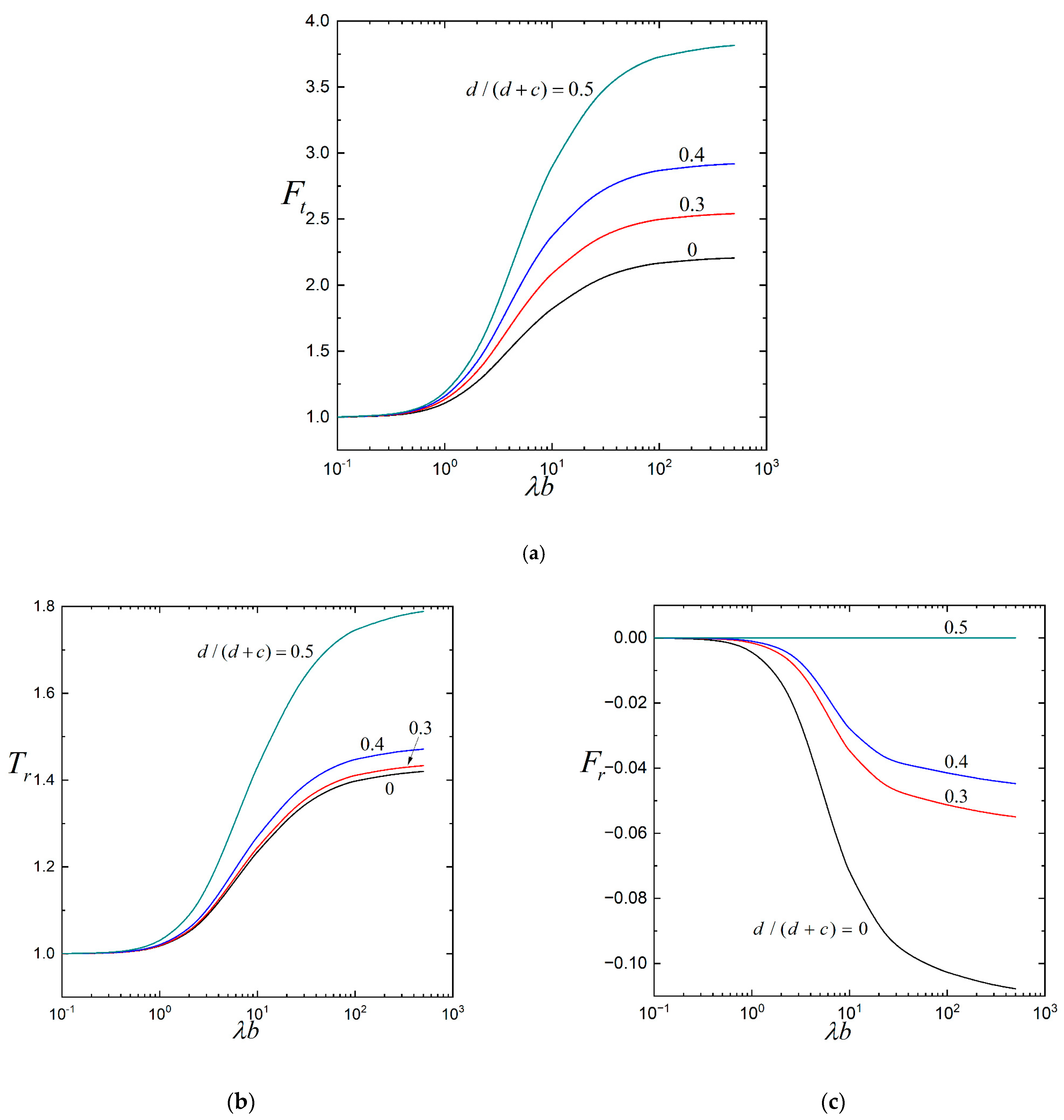
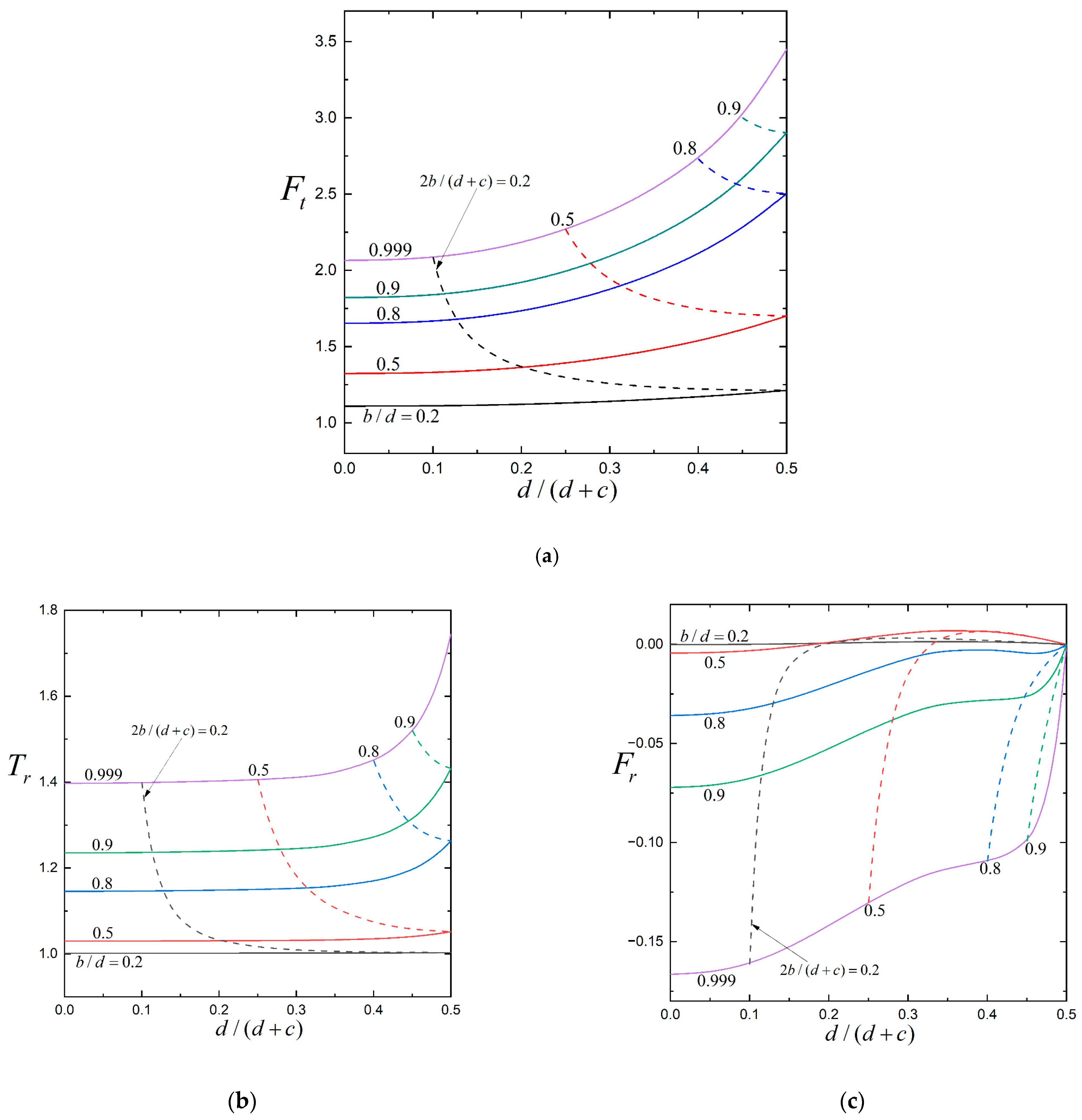
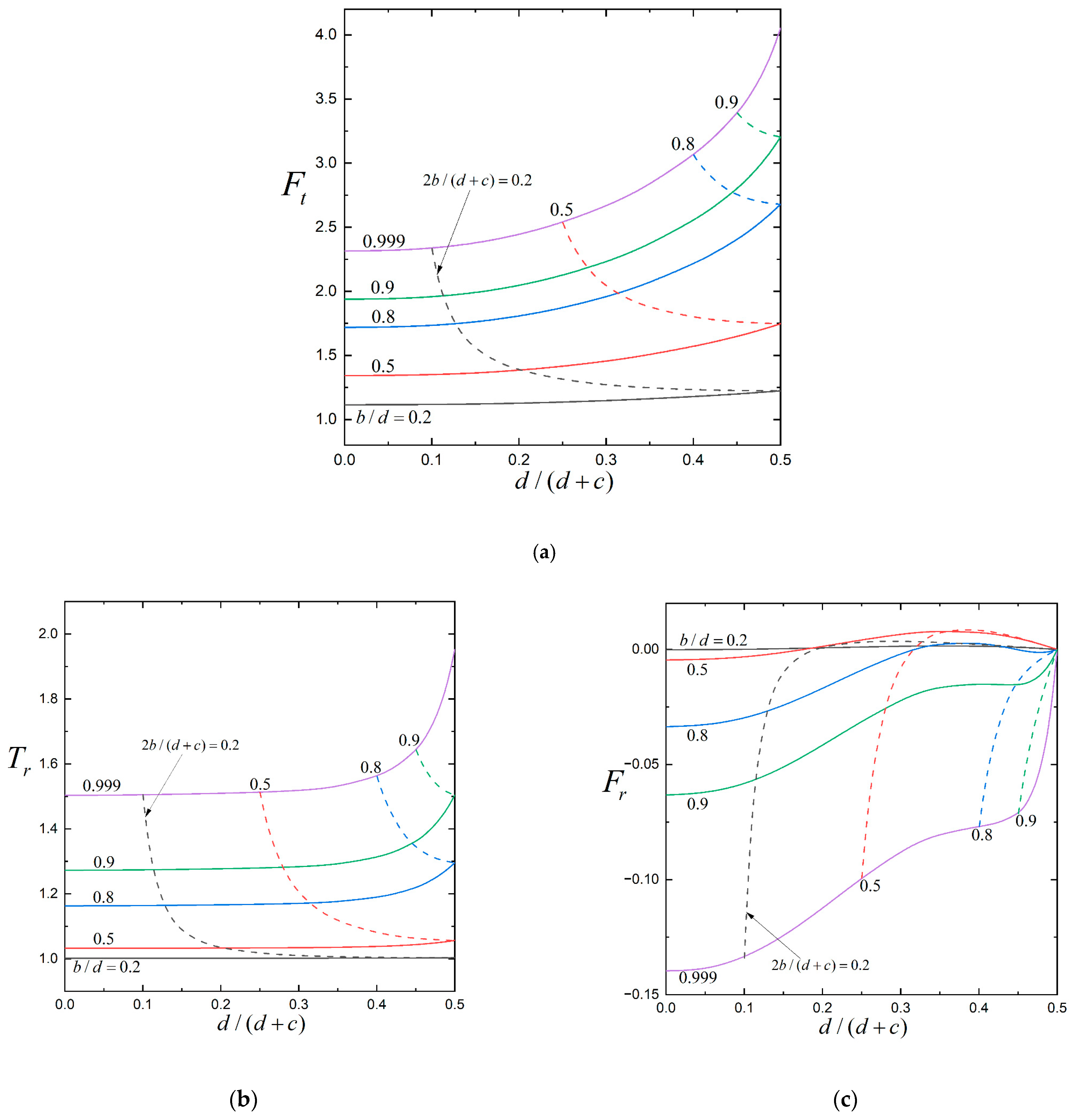
The resistance factors, F t , T r , and F r , for the translation and rotation of a porous sphere ( a = 0 ) parallel to one or two planar walls are plotted against the parameters λ b , b / d , and d / ( d + c ) over the entire range in Figure 2, Figure 3 and Figure 4, respectively. Similar to the circumstances of the translation and rotation of a porous sphere normal to one or two planar walls [28,29], for fixed values of the parameters d / ( d + c ) and λ b , Figure 3 and Figure 4 and Table 1 and Table 2 show that the normalized hydrodynamic drag force and torque that act on the porous particle that translates and rotates parallel to one or two planar walls (or F t and T r , respectively) are monotonic increasing functions of the particle–wall spacing parameter, b / d , from zero to unity (note that F t and T r are still finite even if the particle touches the planar walls). For the given values of b / d and λ b , the drag force and torque increase with an increase in d / ( d + c ) from zero (the case of a particle translating and rotating parallel to a single planar wall) to 1/2, as shown in Figure 2 and Figure 4. That is, the approach of a second planar wall will enhance the hydrodynamic force and torque exerted on the particle near the first wall. For a fixed value of 2 b / ( c + d ) (ratio of particle diameter to wall distance), F t and T r are minimal (the particle experiences minimum drag force and torque) when the particle is halfway between the two walls [ d / ( d + c ) = 1 / 2 ] and increases monotonically as the particle approaches either wall, as shown by the dashed lines in Figure 4.
As demonstrated in Figure 2 and Figure 3, the force and torque factors, F t and T r , for the translation and rotation of a porous sphere increase monotonically with an increasing ratio of particle radius to permeation length, λ b , from unity at λ b = 0 (with F 0 = F = 0 and T 0 = T = 0 ) for given values of b / d and d / ( d + c ) . On the other hand, as revealed in Figure 3 and Figure 4 and Table 3, the coupling factor, F r , is not necessarily a monotonic function of the parameters b / d , d / ( d + c ) , and λ b [there may be extrema at moderate values of b / d , d / ( d + c ) , and λ b ], fixing the other parameters. When λ b is smaller than unity, the variations of all the resistance factors, F t , T r , and F r , with b / d and d / ( d + c ) are weak. In general, these resistance coefficients for a porous sphere with λ b 100 is sufficiently close to those of a hard sphere (with λ b ). A comparison of Figure 2, Figure 3 and Figure 4 and Table 1 and Table 2 shows that the boundary effects of the planar walls on the translation of the particle are much more conspicuous than those on the rotation.
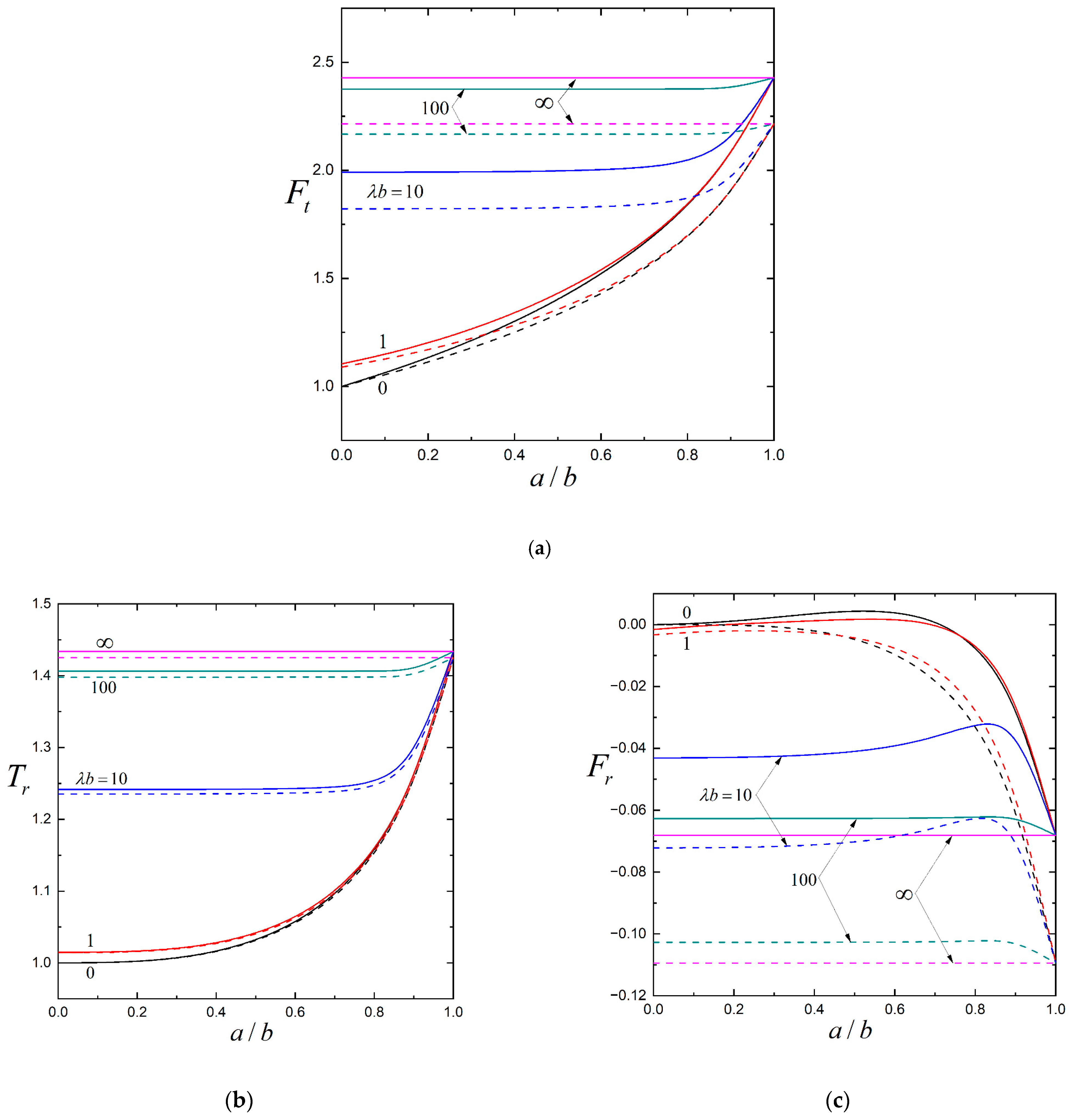
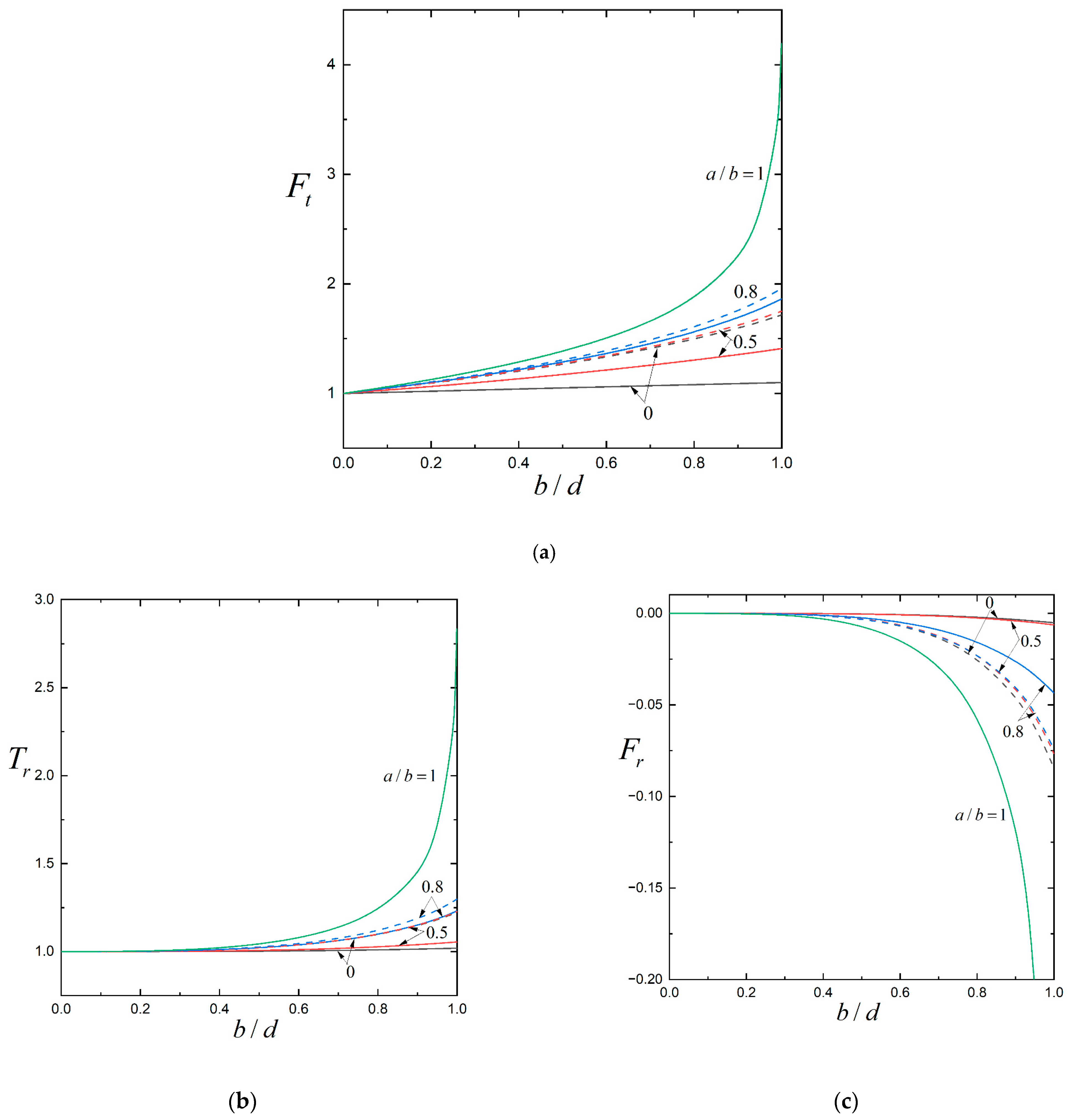
The force, torque, and coupling factors, F t , T r , and F r , for the translation and rotation of a general composite spherical particle parallel to one or two planar walls are plotted in Figure 5, Figure 6 and Figure 7 for various values of the core-to-particle radius ratio, a / b , particle–wall spacing parameter, b / d , relative particle position parameter, d / ( d + c ) , and ratio of particle radius to porous layer permeation length, λ b . Similarly, F t and T r increase monotonically with increases in b / d , λ b , and d / ( d + c ) , fixing the other parameters. For a fixed value of 2 b / ( c + d ) , F t and T r are minimal at d / ( d + c ) = 1 / 2 and increase monotonically with a decrease in d / ( d + c ) . The coupling factor, F r , is not necessarily a monotonic function of b / d , λ b , and d / ( d + c ) , keeping other parameters unchanged. The boundary effects of the planar walls on the translation of the composite particle are much more noticeable than the effects on the rotation.
For specified values of b / d , λ b , and d / ( d + c ) , Table 4 and Figure 5, Figure 6 and Figure 7 demonstrate that the force and torque factors, F t and T r , of a composite sphere that translates and rotates parallel to one or two planar walls monotonically increase with an increase in the radius ratio, a / b (a decrease in the relative thickness of the porous layer), where the limits a / b = 1 and a / b = 0 denote a hard sphere and an entirely porous sphere, respectively. All hydrodynamic force and torque results for a general composite sphere fall between the lower and upper limits of a / b = 0 and a / b = 1 , respectively. On the other hand, the coupling factor, F r , is not necessarily a monotonic function of a / b for fixed values of b / d , λ b , and d / ( d + c ) . When the porous layer of the composite particle has small to moderate permeability (say, λ b > 10 ), as shown in Figure 5, the values of all the resistance factors, F t , T r , and F r , of the composite particle with a / b < 0.8 can be well approximated using the values of a fully porous particle with the same b / d , λ b , and d / ( d + c ) . Namely, the hard core of the composite sphere can hardly feel the relative fluid motion and only exerts negligible hydrodynamic resistance. However, this approximation does not apply to highly permeable porous layers.
Since the governing equations of the general problem for a composite sphere translating and rotating in arbitrary directions near one or two planar walls are linear, its solution can be determined by the superposition of the solutions to its two subproblems: motions parallel to the planar walls, which are examined in the current work, and motions normal to the planar walls. The collocation solutions for the translation and rotation of a composite sphere normal to the planar walls were previously obtained [28,29], and it was found that the wall-corrected normalized drag force and torque acting on the particle also increase with increases in b / d , λ b , d / ( d + c ) , and a / b . Interestingly, comparisons between those results and our solutions indicate that the planar walls exert much more force but less torque on the particle when its translational and rotational motions occur normal to them than when its motions occur parallel to them. Therefore, the directions of translation and rotation of a composite sphere near one or two planar walls are different from those of the imposed force and torque, respectively, except when the directions are parallel or normal to the walls.
In Table 1, Table 2, Table 3 and Table 4 and Figure 2, Figure 3, Figure 4, Figure 5, Figure 6 and Figure 7, we present detailed results pertaining to the resistance problem, which involves evaluating the hydrodynamic force, F , and torque, T , experienced by a composite sphere undergoing prescribed translational and angular velocities, U and Ω , respectively, parallel to one or two planar walls under steady conditions. In contrast, the mobility problem entails determining the resulting particle velocities, U and Ω , when known external force, F , and torque, T , are applied to the composite sphere. For the specific case of the slow translation and rotation of the composite sphere considered in this study, the analytical formulations provided in Equation (19) are equally applicable to the corresponding mobility problem. In particular, for configurations involving free rotational motion parallel to one or two planar walls driven solely by an external force, F , the resulting translational and angular velocities of the composite sphere can be directly obtained via Equation (19), with the following result:
U = F F 0 / U ( F t F r T t T r ) 1
Ω = U b T t T r
where the resistance factors are presented in the aforementioned tables and figures, and the term F 0 / U that appears on the right-hand side of Equation (21a) can be evaluated using Equation (1).

4. Conclusions

The low-Reynolds number-coupled translational and rotational motions of a composite spherical particle (hard core with porous surface layer) in a viscous fluid parallel to one or two planar walls are investigated semi-analytically using a method of boundary collocation. When the core-to-particle radius ratio, a / b , ratio of particle radius to porous layer permeation length, λ b , particle–wall spacing parameter, b / d , and relative particle position parameter, d / ( d + c ) , take arbitrary values, convergent numerical results of the hydrodynamic force and torque acting on the particle are obtained. The normalized drag force and torque increase monotonically with increases in a / b , b / d , λ b , and d / ( d + c ) , keeping other parameters unchanged. For a fixed value of the ratio of particle diameter to wall-to-wall distance, 2 b / ( c + d ) , these force and torque are minimal at d / ( d + c ) = 1 / 2 (as the particle is midway between the two walls) and increase steadily with a decrease in d / ( d + c ) (shorter distance to either wall). The coupling between the translation and rotation of the composite sphere parallel to the walls exhibits complex behavior that does not vary monotonically with changes in system parameters. The influence of the walls on translational motion is significantly stronger than on rotational motion. When comparing particle motions parallel versus normal to the walls, the planar boundaries impose weaker hydrodynamic forces but stronger torques during parallel motions.

Author Contributions

Conceptualization, H.J.K.; methodology, H.J.K. and Y.F.C.; investigation, H.J.K. and Y.F.C.; writing—original draft preparation, H.J.K. and Y.F.C.; writing—review and editing, H.J.K.; supervision, H.J.K.; funding acquisition, H.J.K. All authors have read and agreed to the published version of the manuscript.

Funding

This research was funded by the National Science and Technology Council, Taiwan (Republic of China), under grant number NSTC 113-2221-E-002-063-MY2.

Data Availability Statement

The data is contained within the article.

Conflicts of Interest

The authors declare no conflict of interest. The funders had no role in the design of the study; the collection, analyses, or interpretation of data; the writing of the manuscript; or the decision to publish the results.

Appendix A

By substituting Equations (12)–(17) into Equations (7) and (8), we obtain
n = 1 n ( n + 1 ) P n 1 ( μ ) { C ^ 1 n a n 1 + C ^ 2 n a n 2 + a 3 / 2 [ C ^ 3 n I n + 1 / 2 ( λ a ) + C ^ 4 n K n + 1 / 2 ( λ a ) ] } = 0 ,
n = 1 { [ C ^ 1 n ( n + 1 ) a n 1 + n C ^ 2 n a n 2 + C ^ 3 n { n a 3 / 2 I n + 1 / 2 ( λ a ) λ a 1 / 2 I n 1 / 2 ( λ a ) } + C ^ 4 n { n a 3 / 2 K n + 1 / 2 ( λ a ) + λ a 1 / 2 K n 1 / 2 ( λ a ) } ] ( 1 μ 2 ) 1 / 2 d P n 1 ( μ ) d μ + a 1 / 2 [ D ^ 1 n I n + 1 / 2 ( λ a ) + D ^ 2 n K n + 1 / 2 ( λ a ) ] ( 1 μ 2 ) 1 / 2 P n 1 ( μ ) } = 0 ,
n = 1 { [ C ^ 1 n ( n + 1 ) a n 1 + n C ^ 2 n a n 2 + C ^ 3 n { n a 3 / 2 I n + 1 / 2 ( λ a ) λ a 1 / 2 I n 1 / 2 ( λ a ) } + C ^ 4 n { n a 3 / 2 K n + 1 / 2 ( λ a ) + λ a 1 / 2 K n 1 / 2 ( λ a ) } ] ( 1 μ 2 ) 1 / 2 P n 1 ( μ ) + a 1 / 2 [ D ^ 1 n I n + 1 / 2 ( λ a ) + D ^ 2 n K n + 1 / 2 ( λ a ) ] ( 1 μ 2 ) 1 / 2 d P n 1 ( μ ) d μ } = 0 ,
n = 1 { [ A n A n + B n B n + C n C n ] r = b + λ 2 [ ( n + 1 ) C ^ 1 n b n n C ^ 2 n b n 1 ] P n 1 ( μ ) cos ϕ } = 0 ,
n = 1 { [ A n A n * + B n B n * + C n C n * ] r = b sec ϕ n ( n + 1 ) [ C ^ 1 n b n 1 + C ^ 2 n b n 2 + b 3 / 2 { C ^ 3 n I n + 1 / 2 ( λ b ) + C ^ 4 n K n + 1 / 2 ( λ b ) } ] P n 1 ( μ ) } U ( 1 μ 2 ) 1 / 2 = 0 ,
n = 1 { [ A n A n * * + B n B n * * + C n C n * * ] r = b sec ϕ + [ C ^ 1 n ( n + 1 ) b n 1 n C ^ 2 n b n 2 + C ^ 3 n { λ b 1 / 2 I n 1 / 2 ( λ b ) n b 3 / 2 I n + 1 / 2 ( λ b ) } C ^ 4 n { λ b 1 / 2 K n 1 / 2 ( λ b ) + n b 3 / 2 K n + 1 / 2 ( λ b ) } ] ( 1 μ 2 ) 1 / 2 d P n 1 ( μ ) d μ b 1 / 2 [ D ^ 1 n I n + 1 / 2 ( λ b ) + D ^ 2 n K n + 1 / 2 ( λ b ) ] ( 1 μ 2 ) 1 / 2 P n 1 ( μ ) } U μ Ω b = 0 ,
n = 1 { [ A n A n * * * + B n B n * * * + C n C n * * * ] r = b csc ϕ + [ C ^ 1 n ( n + 1 ) b n 1 n C ^ 2 n b n 2 + C ^ 3 n { λ b 1 / 2 I n 1 / 2 ( λ b ) n b 3 / 2 I n + 1 / 2 ( λ b ) } C ^ 4 n { λ b 1 / 2 K n 1 / 2 ( λ b ) + n b 3 / 2 K n + 1 / 2 ( λ b ) } ] ( 1 μ 2 ) 1 / 2 P n 1 ( μ ) b 1 / 2 [ D ^ 1 n I n + 1 / 2 ( λ b ) + D ^ 2 n K n + 1 / 2 ( λ b ) ] ( 1 μ 2 ) 1 / 2 d P n 1 ( μ ) d μ } + U + Ω b μ = 0 ,
n = 1 { ( r [ A n A n * * + B n B n * * + C n C n * * ] ) r = b sec ϕ + [ ( n + 1 ) ( n 1 ) b n 2 C ^ 1 n + n ( n + 2 ) b n 3 C ^ 2 n b 5 / 2 ( [ ( 1 n 2 λ 2 b 2 ) I n + 1 / 2 ( λ b ) + λ b I n + 3 / 2 ( λ b ) ] C ^ 3 n + [ ( 1 n 2 λ 2 b 2 ) K n + 1 / 2 ( λ b ) λ b K n + 3 / 2 ( λ b ) ] C ^ 4 n ) ] ( 1 μ 2 ) 1 / 2 d P n 1 ( μ ) d μ b 3 / 2 ( [ n I n + 1 / 2 ( λ b ) + λ b I n + 3 / 2 ( λ b ) ] D ^ 1 n + [ n K n + 1 / 2 ( λ b ) λ b K n + 3 / 2 ( λ b ) ] D ^ 2 n ) ( 1 μ 2 ) 1 / 2 P n 1 ( μ ) } Ω = 0 ,
n = 1 { ( r [ A n A n * * * + B n B n * * * + C n C n * * * ] ) r = b csc ϕ + [ ( n + 1 ) ( n 1 ) b n 2 C ^ 1 n + n ( n + 2 ) b n 3 C ^ 2 n b 5 / 2 ( [ ( 1 n 2 λ 2 b 2 ) I n + 1 / 2 ( λ b ) + λ b I n + 3 / 2 ( λ b ) ] C ^ 3 n + [ ( 1 n 2 λ 2 b 2 ) K n + 1 / 2 ( λ b ) λ b K n + 3 / 2 ( λ b ) ] C ^ 4 n ) ] ( 1 μ 2 ) 1 / 2 P n 1 ( μ ) b 3 / 2 ( [ n I n + 1 / 2 ( λ b ) + λ b I n + 3 / 2 ( λ b ) ] D ^ 1 n + [ n K n + 1 / 2 ( λ b ) λ b K n + 3 / 2 ( λ b ) ] D ^ 2 n ) ( 1 μ 2 ) 1 / 2 d P n 1 ( μ ) d μ } + Ω μ = 0 ,
where the starred A n , B n , and C n are functions of position defined by Equation (11) of Chen and Keh [14].
The tetra-primed A n , B n , and C n in Equation (14) are functions of position that are defined by
A n ( r , μ , ϕ ) = 2 n ( 2 n 1 ) r n 1 P n 1 ( μ ) cos ϕ cos ϕ 0 J 1 ( κ ρ ) κ ( τ 2 sinh 2 τ ) [ 2 κ X 1 ( σ , η ) Y n 1 ( d ) 2 κ X 1 ( η , σ ) Y n 1 ( c ) + X 2 ( σ , η ) Y n 2 ( d ) X 2 ( η , σ ) Y n 2 ( c ) ] d κ ,
B n ( r , μ , ϕ ) = cos ϕ 0 J 1 ( κ ρ ) κ ( τ 2 sinh 2 τ ) [ 2 κ X 1 ( σ , η ) n B n + 1 , 1 , 1 , 2 ( d ) 2 κ X 1 ( η , σ ) n B n + 1 , 1 , 1 , 2 ( c ) κ 2 X 2 ( σ , η ) Y n 4 ( d ) + κ 2 X 2 ( η , σ ) Y n 4 ( c ) ] d κ ,
C n ( r , μ , ϕ ) = cos ϕ 0 J 1 ( κ ρ ) κ ( τ 2 sinh 2 τ ) [ 2 κ X 1 ( σ , η ) B n , 1 , 1 , 2 ( d ) 2 κ X 1 ( η , σ ) B n , 1 , 1 , 2 ( c ) κ 2 X 2 ( σ , η ) Y n 3 ( d ) + κ 2 X 2 ( η , σ ) Y n 3 ( c ) ] d κ ,
where σ = κ ( z + d ) , η = κ ( z c ) , τ = κ ( c + d ) ,
X 1 ( δ , ν ) = τ cosh δ + cosh ν sinh τ ,
X 2 ( δ , ν ) = τ sinh δ sinh ν sinh τ ,
Y n 1 ( z ) = ( n + 1 ) ( n 2 ) B n 1 , 1 , 1 , 2 ( z ) n ( 2 n 1 ) z B n , 1 , 1 , 2 ( z ) ,
Y n 2 ( z ) = n ( n + 1 ) ( n 2 ) κ 2 B n 1 , 0 , 0 , 1 ( z ) + ( n 2 ) κ 2 z 2 B n 1 , 2 , 2 , 1 ( z ) 2 n ( 2 n 1 ) [ B n , 1 , 1 , 2 ( z ) κ 2 z 2 B n , 1 , 2 , 1 ( z ) ] ,
Y n 3 ( z ) = n ( n + 1 ) B n , 0 , 0 , 1 ( z ) z 2 B n , 2 , 2 , 1 ( z ) ,
Y n 4 ( z ) = n ( n + 1 ) B n + 1 , 0 , 0 , 1 ( z ) + z 2 B n + 1 , 2 , 2 , 1 ( z ) ,
J 1 is the Bessel function of the first kind of order one, and the function B n , m , j , l ( z ) is defined by Equation (C5) of Ganatos et al. [13].

References

  1. Stokes, G.G. On the theories of the internal friction of fluids in motion and of the equilibrium and motion of elastic solids. Trans. Camb. Phil. Soc. 1845, 8, 287–319. [Google Scholar]
  2. Stokes, G.G. On the effect of the internal friction of fluids on the motion of pendulums. Trans. Cambridge Phil. Soc. 1851, 9, 8–106. [Google Scholar]
  3. Masliyah, J.H.; Neale, G.; Malysa, K.; van de Ven, T.G.M. Creeping flow over a composite sphere: Solid core with porous shell. Chem. Eng. Sci. 1987, 42, 245–253. [Google Scholar] [CrossRef]
  4. Keh, H.J.; Chou, J. Creeping motion of a composite sphere in a concentric spherical cavity. Chem. Eng. Sci. 2004, 59, 407–415. [Google Scholar] [CrossRef]
  5. Wunderlich, R.W. The effects of surface structure on the electrophoretic mobilities of large particles. J. Colloid Interface Sci. 1982, 88, 385–397. [Google Scholar] [CrossRef]
  6. Anderson, J.L.; Solomentsev, Y. Hydrodynamic effects of surface layer on colloidal particles. Chem. Eng. Comm. 1996, 148–150, 291–314. [Google Scholar] [CrossRef]
  7. Napper, D.H. Polymeric Stabilization of Colloidal Dispersions; Academic Press: London, UK, 1983. [Google Scholar]
  8. Neale, G.; Epstein, N.; Nader, W. Creeping flow relative to permeable spheres. Chem. Eng. Sci. 1973, 28, 1865–1874. [Google Scholar] [CrossRef]
  9. Happel, J.; Brenner, H. Low Reynolds Number Hydrodynamics; Nijhoff: Dordrecht, The Netherlands, 1983. [Google Scholar]
  10. Anderson, J.L. Colloid transport by interfacial forces. Ann. Rev. Fluid Mech. 1989, 21, 61–99. [Google Scholar] [CrossRef]
  11. Romanò, F.; des Boscs, P.-E.; Kuhlmann, H.C. Forces and torques on a sphere moving near a dihedral corner in creeping flow. Eur. J. Mech. B Fluids 2020, 84, 110–121. [Google Scholar] [CrossRef]
  12. Goldman, A.J.; Cox, R.G.; Brenner, H. Slow viscous motion of a sphere parallel to a plane wall-I. Motion through a quiescent fluid. Chem. Eng. Sci. 1967, 22, 637–651. [Google Scholar] [CrossRef]
  13. Ganatos, P.; Pfeffer, R.; Weinbaum, S. A strong interaction theory for the creeping motion of a sphere between plane parallel boundaries. Part 2. Parallel motion. J. Fluid Mech. 1980, 99, 755–783. [Google Scholar] [CrossRef]
  14. Chen, P.Y.; Keh, H.J. Slow motion of a slip spherical particle parallel to one or two plane walls. J. Chin. Inst. Chem. Engrs. 2003, 34, 123–133. [Google Scholar]
  15. Sherief, H.H.; Faltas, M.S.; Ashmawy, E.A.; Nashwan, M.G. Slow motion of a slip spherical particle along the axis of a circular cylindrical pore in a micropolar fluid. J. Mol. Liq. 2014, 200, 273–282. [Google Scholar] [CrossRef]
  16. Papavassiliou, D.; Alexander, G.P. Exact solutions for hydrodynamic interactions of two squirming spheres. J. Fluid Mech. 2017, 813, 618–646. [Google Scholar] [CrossRef]
  17. Chou, C.Y.; Keh, H.J. Slow rotation of a spherical particle in an eccentric spherical cavity with slip surfaces. Eur. J. Mech. B Fluids 2021, 86, 150–156. [Google Scholar] [CrossRef]
  18. Lee, M.C.; Keh, H.J. Slow axisymmetric rotation of a sphere in a circular tube with slip surfaces. Fluid Dyn. Res. 2021, 53, 065502. [Google Scholar] [CrossRef]
  19. Nashwan, M.G.; Ragab, K.E.; Faltas, M.S. Axisymmetric slow motion of a non-deformable spherical droplet or slip particle toward an orifice in a plane wall. Phys. Fluids 2022, 34, 083106. [Google Scholar] [CrossRef]
  20. Liao, J.C.; Keh, H.J. Slow rotation of a sphere about its diameter normal to two planes with slip surfaces. Fluid Dyn. Res. 2022, 54, 035502. [Google Scholar] [CrossRef]
  21. Madasu, K.P. Boundary effects of slow flow past a fluid coated sphere. Phys. Fluids 2025, 37, 031908. [Google Scholar] [CrossRef]
  22. Srinivasacharya, D.; Krishna Prasad, M. Steady rotation of a composite sphere in a concentric spherical cavity. Acta Mech. Sin. 2012, 28, 653–658. [Google Scholar] [CrossRef]
  23. Prakash, J.; Raja Sekhar, G.P. Slow motion of a porous spherical particle with a rigid core in a spherical fluid cavity. Meccanica 2017, 52, 91–105. [Google Scholar] [CrossRef]
  24. Chou, C.Y.; Keh, H.J. Low-Reynolds-number rotation of a soft particle inside an eccentric cavity. Eur. J. Mech. B Fluids 2022, 91, 194–201. [Google Scholar] [CrossRef]
  25. Chen, Y.C.; Keh, H.J. Slow translation of a composite sphere in an eccentric spherical cavity. Fluids 2024, 9, 154. [Google Scholar] [CrossRef]
  26. Chen, Y.C.; Keh, H.J. Slow translation and rotation of a composite sphere within a nonconcentric spherical cavity normal to their common diameter. Fluid Dyn. Res. 2025, 54, 035502. [Google Scholar] [CrossRef]
  27. Jhuang, L.J.; Keh, H.J. Slow axisymmetric rotation of a soft sphere in a circular cylinder. Eur. J. Mech. B Fluids 2022, 95, 205–211. [Google Scholar] [CrossRef]
  28. Chen, S.B.; Ye, X. Boundary effect on slow motion of a composite sphere perpendicular to two parallel impermeable plates. Chem. Eng. Sci. 2000, 55, 2441–2453. [Google Scholar] [CrossRef]
  29. Chang, C.L.; Keh, H.J. Slow rotation of a soft colloidal sphere normal to two plane walls. Colloids Interfaces 2023, 7, 18. [Google Scholar] [CrossRef]
  30. Koplik, J.; Levine, H.; Zee, A. Viscosity renormalization in the Brinkman equation. Phys. Fluids 1983, 26, 2864–2870. [Google Scholar] [CrossRef]
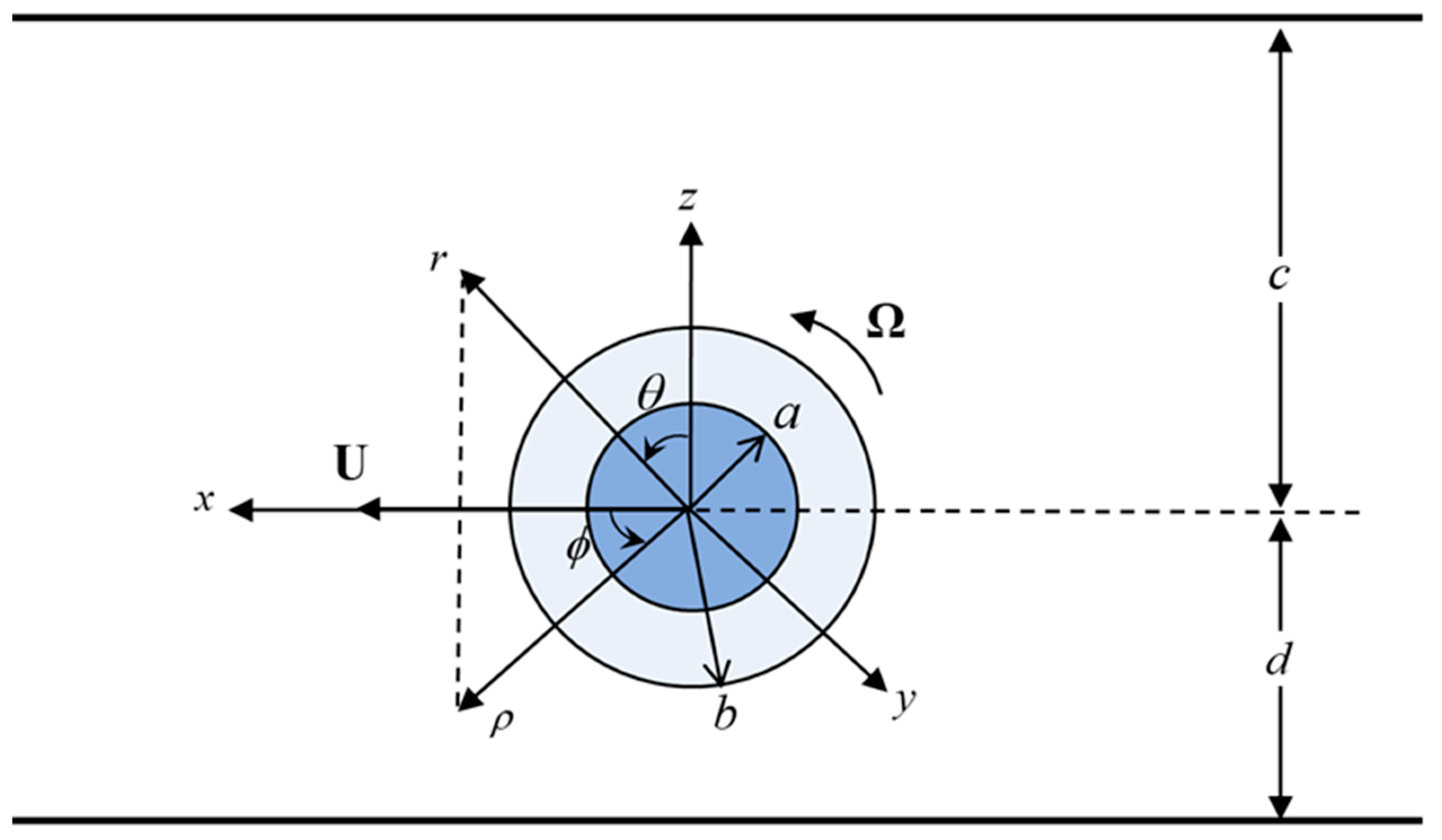
Figure 1. Schematic illustration of the translation and rotation of a composite sphere parallel to two plane walls at an arbitrary position between them.
Fluids 10 00154 g001
Figure 2. Resistance factors for the motions of a porous sphere ( a = 0 ) parallel to two planar walls versus the shielding parameter, λ b , with b / d = 0.9 and various values of d / ( d + c ) : (a) F t ; (b) T r ; (c) F r .
Fluids 10 00154 g002
Figure 3. Resistance factors for the motions of a porous sphere ( a = 0 ) parallel to two planar walls versus the spacing parameter, b / d , with d / ( d + c ) = 0.25 and various value of λ b : (a) F t ; (b) T r ; (c) F r .
Fluids 10 00154 g003
Figure 4. Resistance factors for the motions of a porous sphere ( a = 0 ) parallel to two planar walls versus the relative particle position parameter, d / ( d + c ) , with λ b = 10 and various values of b / d and 2 b / ( d + c ) : (a) F t ; (b) T r ; (c) F r .
Fluids 10 00154 g004
Figure 5. Resistance factors for the motions of a composite sphere parallel to two planar walls versus the core-to-particle radius ratio, a / b , with b / d = 0.9 and various values of λ b : (a) F t ; (b) T r ; (c) F r . The solid and dashed curves denote cases of d / ( d + c ) = 0.25 and d / ( d + c ) = 0 , respectively.
Fluids 10 00154 g005
Figure 6. Resistance factors for the motions of a composite sphere parallel to two planar walls versus the spacing parameter, b / d , with d / ( d + c ) = 0 and various values of a / b : (a) F t ; (b) T r ; (c) F r . The solid and dashed curves denote cases of λ b = 1 and λ b = 5 , respectively.
Fluids 10 00154 g006
Figure 7. Resistance factors for the motions of a composite sphere parallel to two planar walls versus the relative position parameter, d / ( d + c ) , with λ b = 10 , a / b = 0.9 , and various values of b / d and 2 b / ( d + c ) : (a) F t ; (b) T r ; (c) F r .
Fluids 10 00154 g007
Table 1. Force factor, F t , for the translation of a porous sphere parallel to two planar walls at various values of d / ( d + c ) , b / d , and λ b .
d/(d+c) b/dFt
λb = 1 λb = 10 λb = 100 λb = 300 λb→∞
00.11.0100 1.0525 1.0588 1.0593 1.0595
0.21.0200 1.1103 1.1244 1.1254 1.1259
0.31.0302 1.1740 1.1979 1.1995 1.2003
0.41.0403 1.2448 1.2810 1.2835 1.2847
0.51.0503 1.3243 1.3773 1.3810 1.3828
0.61.0602 1.4154 1.4926 1.4980 1.5006
0.71.0700 1.5225 1.6380 1.6463 1.6503
0.81.0797 1.6531 1.8381 1.8522 1.8591
0.91.0893 1.8219 2.1672 2.1995 2.2152
0.991.0980 2.0377 2.9709 3.2285 3.3975
0.9991.0988 2.0656 3.2048 3.6843 4.1929
0.250.11.0116 1.0614 1.0689 1.0694 1.0697
0.21.0233 1.1302 1.1471 1.1483 1.1489
0.31.0352 1.2071 1.2361 1.2381 1.2391
0.41.0470 1.2936 1.3382 1.3412 1.3427
0.51.0588 1.3916 1.4568 1.4613 1.4635
0.61.0704 1.5039 1.5983 1.6048 1.6080
0.71.0818 1.6351 1.7738 1.7836 1.7884
0.81.0931 1.7927 2.0082 2.0243 2.0322
0.91.1042 1.9912 2.3759 2.4109 2.4279
0.991.1142 2.2359 3.2183 3.4792 3.6724
0.9991.1152 2.2668 3.4570 3.9392 4.4494
0.50.11.0179 1.0975 1.1099 1.1107 1.1111
0.21.0362 1.2134 1.2432 1.2452 1.2462
0.31.0545 1.3504 1.4041 1.4078 1.4096
0.41.0727 1.5114 1.5980 1.6039 1.6068
0.51.0904 1.7002 1.8324 1.8413 1.8458
0.61.1074 1.9222 2.1194 2.1329 2.1395
0.71.1236 2.1854 2.4818 2.5024 2.5124
0.81.1387 2.5033 2.9690 3.0029 3.0194
0.91.1530 2.9019 3.7294 3.8019 3.8369
0.991.1652 3.3877 5.4403 5.9675 6.2597
0.9991.1664 3.4488 5.9201 6.8900 7.6253
Table 2. Torque factor, T r , for the rotation of a porous sphere parallel to two planar walls at various values of d / ( d + c ) , b / d , and λ b .
d/(d+c) b/dTr
λb = 1 λb = 10 λb = 100 λb = 300 λb→∞
00.11.0000 1.0002 1.0003 1.0003 1.0003
0.21.0002 1.0018 1.0024 1.0025 1.0025
0.31.0005 1.0062 1.0083 1.0085 1.0086
0.41.0012 1.0149 1.0200 1.0205 1.0207
0.51.0024 1.0299 1.0405 1.0413 1.0418
0.61.0041 1.0536 1.0737 1.0754 1.0763
0.71.0066 1.0899 1.1274 1.1307 1.1324
0.81.0099 1.1457 1.2182 1.2249 1.2283
0.91.0142 1.2352 1.3980 1.4161 1.4253
0.991.0190 1.3768 1.9369 2.1072 2.2233
0.9991.0195 1.3974 2.1150 2.4519 2.8341
0.250.11.0000 1.0002 1.0003 1.0003 1.0003
0.21.0002 1.0019 1.0025 1.0026 1.0026
0.31.0005 1.0065 1.0086 1.0088 1.0089
0.41.0013 1.0155 1.0208 1.0213 1.0215
0.51.0025 1.0310 1.0420 1.0429 1.0433
0.61.0043 1.0555 1.0763 1.0781 1.0789
0.71.0068 1.0929 1.1314 1.1348 1.1365
0.81.0103 1.1502 1.2241 1.2309 1.2344
0.91.0147 1.2415 1.4062 1.4244 1.4337
0.991.0197 1.3850 1.9476 2.1182 2.2463
0.9991.0203 1.4057 2.1262 2.4631 2.8455
0.50.11.0000 1.0004 1.0005 1.0005 1.0005
0.21.0003 1.0031 1.0042 1.0043 1.0043
0.31.0009 1.0107 1.0143 1.0146 1.0147
0.41.0021 1.0258 1.0347 1.0354 1.0358
0.51.0041 1.0519 1.0707 1.0722 1.0730
0.61.0071 1.0940 1.1304 1.1335 1.1351
0.71.0113 1.1598 1.2289 1.2350 1.2381
0.81.0170 1.2629 1.3996 1.4123 1.4188
0.91.0243 1.4318 1.7463 1.7815 1.7994
0.991.0327 1.7046 2.8108 3.1503 3.3477
0.9991.0336 1.7446 3.1658 3.8382 4.3955
Table 3. Coupling factor, F r = T t ( T 0 / b 2 Ω ) / ( F 0 / U ) , for the translation and rotation of a porous sphere parallel to two planar walls at various values of d / ( d + c ) , b / d , and λ b .
d/(d+c) b/dFr
λb = 1 λb = 10 λb = 100 λb = 300 λb→∞
00.1−4.7 × 10⁻⁷−7.4 × 10⁻⁶−1.1 × 10⁻⁵−1.2 × 10⁻⁵−1.2 × 10⁻⁵
0.2−7.5 × 10⁻⁶−1.2 × 10⁻⁴−1.8 × 10⁻⁴−1.8 × 10⁻⁴−1.8 × 10⁻⁴
0.3−3.8 × 10⁻⁵−5.7 × 10⁻⁴−8.6 × 10⁻⁴−8.9 × 10⁻⁴−9.0 × 10⁻⁴
0.4−1.2 × 10⁻⁴−0.0018 −0.0026 −0.0027 −0.0028
0.5−3.0 × 10⁻⁴−0.0044 −0.0064 −0.0066 −0.0067
0.6−6.3 × 10⁻⁴−0.0094 −0.0134 −0.0138 −0.0141
0.7−0.0012 −0.0186 −0.0261 −0.0270 −0.0275
0.8−0.0020 −0.0359 −0.0499 −0.0517 −0.0527
0.9−0.0033 −0.0722 −0.1027 −0.1067 −0.1095
0.99−0.0049 −0.1526 −0.3486 −0.3640 −0.3852
0.999−0.0051 −0.1665 −0.4881 −0.6124 −0.8240
0.250.12.0 × 10−52.5 × 10−43.3 × 10−43.4 × 10−43.4 × 10−4
0.27.6 × 10−59.9 × 10−40.0013 0.0013 0.0013
0.31.5 × 10−40.0020 0.0027 0.0027 0.0028
0.42.2 × 10−40.0031 0.0040 0.0041 0.0041
0.52.3 × 10−40.0036 0.0045 0.0045 0.0046
0.61.4 × 10−40.0026 0.0029 0.0028 0.0028
0.7−1.2 × 10⁻⁴−0.0018 −0.0031 −0.0035 −0.0037
0.8−6.6 × 10⁻⁴−0.0134 −0.0190 −0.0201 −0.0209
0.9−0.0016 −0.0431 −0.0627 −0.0658 −0.0681
0.99−0.0028 −0.1169 −0.2994 −0.3136 −0.3121
0.999−0.0030 −0.1301 −0.4384 −0.5610 −0.7720
Table 4. Resistance factors for the translation and rotation of a composite sphere where λ b = 1 parallel to two planar walls, with different values of d / d + c , b / d , and a / b .
d/(d+c) b/d a/b = 0.8 a/b = 0.95
FtTrFrFtTrFr
00.11.0472 1.0002 −4.0 × 10−61.0564 1.0003 −9.3 × 10⁻⁶
0.21.0987 1.0013 −6.3 × 10−51.1189 1.0022 −1.4 × 10⁻⁴
0.31.1551 1.0044 −3.1 × 10−41.1885 1.0073 −7.0 × 10⁻⁴
0.41.2170 1.0105 −9.5 × 10−41.2669 1.0176 −0.0022
0.51.2857 1.0209 −0.0023 1.3567 1.0355 −0.0052
0.61.3632 1.0371 −0.0046 1.4627 1.0642 −0.0108
0.71.4523 1.0612 −0.0087 1.5932 1.1095 −0.0208
0.81.5581 1.0966 −0.0152 1.7655 1.1831 −0.0385
0.91.6893 1.1493 −0.0257 2.0243 1.3154 −0.0734
0.991.8435 1.2215 −0.0413 2.4836 1.5924 −0.1525
0.9991.8617 1.2307 −0.0434 2.5641 1.6447 −0.1681
0.250.11.0552 1.0002 1.8 × 10−41.0660 1.0003 2.9 × 10⁻⁴
0.21.1163 1.0013 7.1 × 10−41.1405 1.0022 0.0012
0.31.1841 1.0046 0.0015 1.2248 1.0076 0.0024
0.41.2595 1.0109 0.0025 1.3208 1.0183 0.0037
0.51.3439 1.0217 0.0033 1.4314 1.0368 0.0044
0.61.4394 1.0384 0.0037 1.5616 1.0665 0.0035
0.71.5490 1.0633 0.0030 1.7200 1.1131 −6.4 × 10⁻⁴
0.81.6778 1.0998 0.0006 1.9241 1.1883 −0.0115
0.91.8346 1.1538 −0.0053 2.2186 1.3227 −0.0383
0.992.0144 1.2274 −0.0161 2.7136 1.6019 −0.1093
0.9992.0353 1.2367 −0.0177 2.7979 1.6545 −0.1239
Disclaimer/Publisher’s Note: The statements, opinions and data contained in all publications are solely those of the individual author(s) and contributor(s) and not of MDPI and/or the editor(s). MDPI and/or the editor(s) disclaim responsibility for any injury to people or property resulting from any ideas, methods, instructions or products referred to in the content.