Article

Investigation of Heat Transfer Enhancement Mechanisms in Elastic Tube Bundles Subjected to Exogenous Self-Excited Fluid Oscillation

1
School of Physics, Electronics and Intelligent Manufacturing, Huaihua University, Huaihua 418000, China
2
Key Laboratory of Intelligent Control Technology for Wuling-Mountain Ecological Agriculture in Hunan Province, Huaihua 418000, China
3
Institute of Thermal Science & Technology, Shandong University, Jinan 250000, China
*
Author to whom correspondence should be addressed.
Fluids 2025, 10(5), 122; https://doi.org/10.3390/fluids10050122
Submission received: 9 April 2025 / Revised: 30 April 2025 / Accepted: 1 May 2025 / Published: 8 May 2025

Abstract

:
Flow-induced vibration (FIV) characteristics are key factors in enhancing heat transfer. However, challenges such as insufficient heat transfer enhancement and the fatigue strength of the tube bundle persist in the context of improving the heat transfer in elastic tube bundle heat exchangers. This study proposes a novel passive heat transfer enhancement paradigm for elastic tube bundles based on externally induced self-excited oscillations of fluid. By constructing a non-contact energy transfer system, the external oscillation energy is directed into the elastic tube bundle heat exchanger, achieving dynamic stress buffering and breaking through the steady-state flow heat transfer boundary layer. A three-dimensional fluid–structure interaction numerical model is established using Star CCM+2021.3 (16.06.008) to conduct a comparative analysis of the flow characteristics and heat transfer performance between the original structure without an oscillator and the improved structure equipped with a fluid oscillator. The results indicate that the improved structure, through the periodic unsteady jet induced by the fluid oscillator, significantly enhances the turbulence intensity of the shell-side fluid, with the turbulent kinetic energy increasing by over 50%. The radial flow area is notably expanded, thereby reducing the thermal resistance of the boundary layer. At cooling fluid velocities of 6 to 9 m/s, the heat transfer capability of the improved structure is enhanced by more than 50%. Compared with the original structure, the new structure, due to the loading of an external oscillation structure, causes the cold air to present a periodic up and down jet phenomenon. This jet phenomenon, on the one hand, increases the heat exchange area between the cold air and the outer surface of the tube bundle, thereby enhancing the heat exchange capacity. On the other hand, the large-area impact of the fluid reduces the thickness of the boundary layer, lowers the thermal resistance and thereby enhances the heat exchange capacity. Furthermore, this improved structure buffers the mechanical vibrations through self-excited oscillations of the fluid medium, ensuring that the stress levels in the tube bundle remain below the fatigue threshold, effectively mitigating the failure risks associated with traditional active vibration strategies.

1. Introduction

Thermal enhancement technologies are crucial for improving the energy efficiency of energy systems and have significant application value in engineering fields such as nuclear reactor heat exchangers and gas turbine cooling [1,2,3,4]. In recent years, researchers have systematically explored two typical heat transfer enhancement mechanisms: flow-induced vibration (FIV) and self-excited jet flows, achieving significant advancements in both theoretical modeling and engineering applications.
In the field of flow-induced vibration technology, the dynamic control of elastic tube bundles has become a focal point of the research. Cheng’s team [5] innovatively developed a fluid–structure coupled tube bundle structure, enhancing the heat transfer efficiency by 23–28% through precise matching of the vibration modes, providing a paradigm for the interdisciplinary study of structural dynamics and heat transfer. Building on this foundation, Ji et al. [6,7,8,9] systematically investigated the enhancement effects of non-traditional geometric configurations, confirming that vortex tube bundles and double-row helical structures could achieve heat transfer gains of 15–30% under controlled vibration conditions, thereby revealing a strong correlation between geometric parameters and vibration characteristics. Notably, the elastic joint vortex-induced vibration strategy proposed by Su et al. [10] overcame the limitations of traditional rigid connections, increasing the turbulence intensity by 40% while maintaining structural integrity, offering new insights into addressing vibration fatigue issues.
In experimental research, Sukhotski et al. [11] quantified the enhanced heat transfer characteristics of finned tubes under low Reynolds number (Re < 500) conditions, discovering that their heat flux improved by up to 20% compared to conventional tubes, although this technology also exposed limitations in the adaptability to low flow conditions. The vibration model of helical tube arrays established by Ding et al. [12] correlated the vibration frequency and the flow velocity through the Strouhal number (St = 0.2–0.4) and was validated using the FIVPAK code developed by Khushnood et al. [13], with the prediction errors controlled within 8%, providing theoretical support for engineering parameter optimization. Arani et al. [14] utilized an elliptical tube and baffle combination to reduce the pressure drop in double-shell heat exchangers by 18%, while the Blaszczuk team [15] significantly enhanced the performance of large external heat exchangers through a 40% displacement optimization of the inlet header in high heat flux regions. Breakthroughs in fluid–structure coupling modeling have been achieved, with Dimitrios et al. [16] constructing a shell–tube coupling dynamics model that demonstrated a 2.5-fold nonlinear increase in the vibration amplitude when the inlet flow velocity exceeded 3 m/s. Ji’s team [17,18,19] confirmed that a 30–45° fan-shaped baffle layout could simultaneously achieve a 22% increase in the heat transfer coefficient and a reduction in the stress concentration coefficients. In the field of structural durability, Yan et al. [20] and Duan et al. [21] determined the applicability of nickel-based alloys under conditions of σ_max > 150 MPa through fatigue damage tolerance analysis, while Liu et al. [22] established a critical flow velocity ratio criterion (1.2–1.8) to provide design boundaries for preventing flow-induced elastic instability. However, the existing research indicates that there are still upper limits to the heat transfer gains achievable through flow-induced vibration technology and structural improvements, and the issue of material fatigue under long-term operation has not yet been fully resolved.
Self-excited jet enhancement heat transfer technology has garnered widespread attention due to its active control characteristics. Ming et al. [23] revealed the vortex evolution patterns of inclined self-excited oscillating fluid oscillator arrays through unsteady RANS simulations, demonstrating their effectiveness in enhancing turbulent mixing. Kong et al. [24] employed a conjugate-heat-transfer–URANS coupling approach for comparative analysis and found that the impact cooling efficiency of sweeping jets improved by 18.7% compared to steady jets, attributed to the unique secondary flow structure that enhanced the uniformity of the film coverage. Tu et al. [25] further discovered that the Coanda effect generated by confined concave surfaces could increase the wall attachment length of sweeping jets by 35%, significantly expanding the effective cooling area.
In the context of phase change heat transfer in film cooling, Abdelmaksoud et al. [26] utilized multiphase flow simulations to elucidate the coupling mechanisms of droplet dynamics and heat transfer, proving that droplet evaporation could enhance the cooling efficiency by an additional 12–15%. A review by Hussain et al. [27] noted that dual-feedback fluid oscillators, through structural optimization, could increase the sweeping frequency of jets by 40%, although this also led to increased flow losses. Comparative studies by Rezaei et al. [28] indicated that the concave impact jet produced by vortex oscillators achieved a 22% increase in the heat transfer coefficient over traditional configurations, owing to the enhanced vorticity transport characteristics. Notably, Li et al. [29] introduced piezoelectric driving technology into the field of impact jets, finding that dynamic excitation could enhance the local Nusselt number by up to 2.6 times, opening up new avenues for low-energy active control. However, the existing research indicates that the design of self-excited jet configurations lacks universal theoretical guidance, and the multiphysical coupling mechanisms remain inadequately understood.
A comprehensive analysis of the existing literature reveals that the current research on enhancing the heat transfer capabilities of elastic tube bundle heat exchangers primarily focuses on improvements related to the vibration of planar elastic tube bundles and the structure of self-excited jets. Consequently, these limitations have hindered the large-scale engineering application and widespread adoption of this technology in practical industrial settings. However, the limitations in heat transfer enhancement and the issues related to the fatigue strength of the tube bundles restrict the overall heat exchange performance of these systems. Furthermore, the passive heat transfer enhancement methods for elastic tube bundles under externally induced fluid self-excited oscillation conditions have not been sufficiently elucidated, particularly regarding the three-phase (liquid, gas, solid) coupling heat transfer mechanisms and the associated heat transfer gains.
In light of the dual challenges faced by current technologies—namely, (1) the active vibration-based enhancement strategies lead to the accumulation of alternating stresses, increasing the risk of fatigue failure in the tube bundles; and (2) the optimization of structural parameters exhibits diminishing returns in heat transfer gains—this study proposes a novel paradigm for heat transfer through externally induced fluid self-excited oscillation. This approach involves the construction of a non-contact energy transfer system that directs external oscillatory energy into the system.
The proposed solution offers the following dual advantages: (1) it utilizes the fluid medium to buffer the dynamic stresses, ensuring that the stress levels in the tube bundles remain below the fatigue threshold; and (2) it leverages the oscillation effect to surpass the heat transfer limits of steady-state flow, thereby enhancing the heat exchange capacity of the tube bundles.

2. The Numerical Simulation Approach

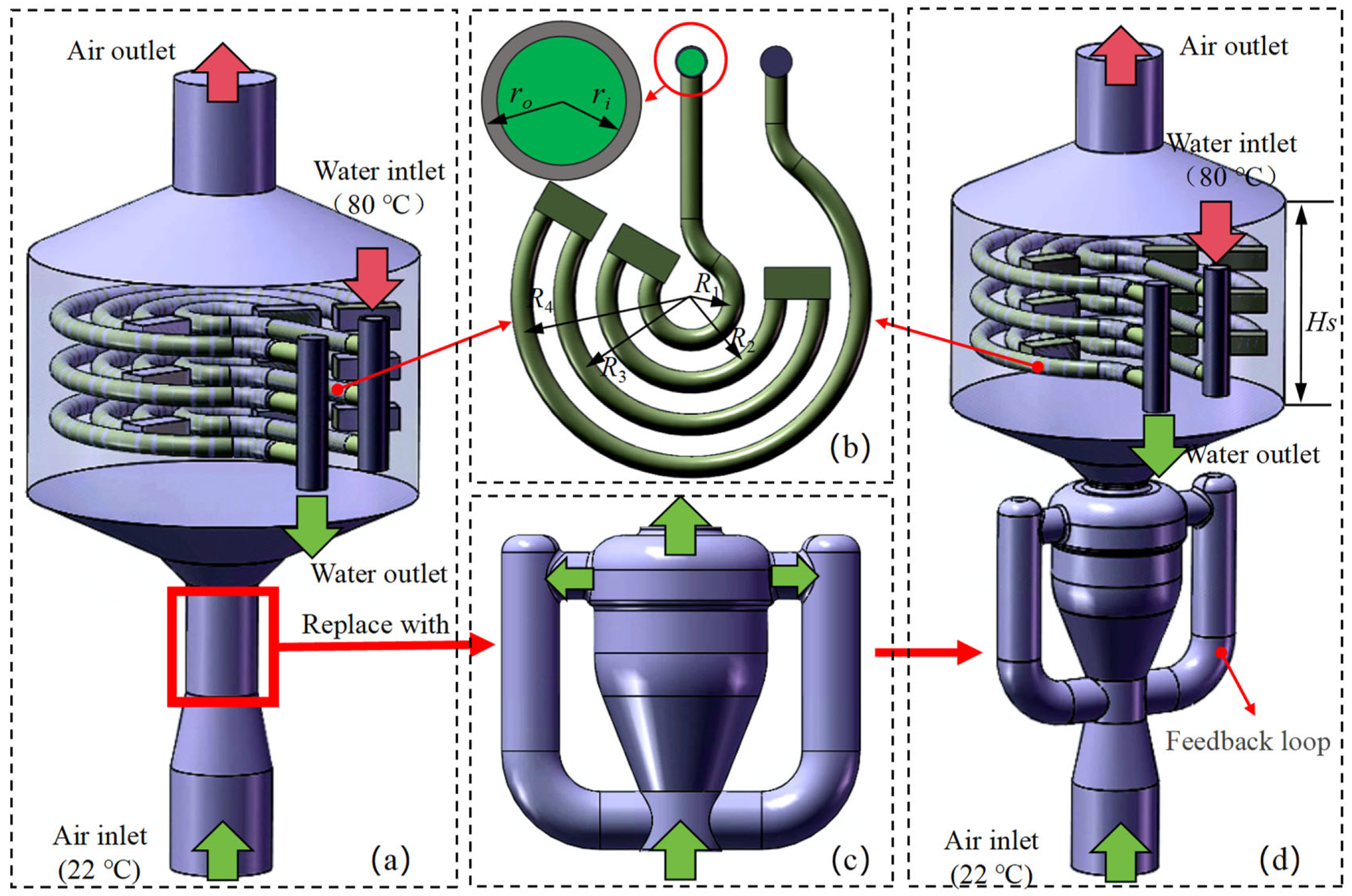
2.1. Geometric Structure

The experimental setup involved in this study comprises two typical structures: the original direct-flow heat exchanger (referred to as the original structure or non-self-excited oscillation structure) and the improved heat exchanger equipped with an external fluid oscillator (referred to as the improved structure or self-excited oscillation structure). The geometric configurations of these structures are detailed in Figure 1. The core heat transfer unit employs a three-tier plane tube bundle array (Figure 1b). This tube bundle system consists of four groups of bent copper tubes with curvature radii ranging from R1 to R4, along with three groups of counterweight modules characterized by geometric dimensions of L × W × H. The internal high-temperature working fluid is hot water, with the characteristic dimensions including the inner radius (ri) and outer radius (ro). The casing serves as a sealed flow channel for the cooling air, with a height denoted as (Hs).
The core innovation of the improved structure lies in the integration of a fluid oscillator based on the Coanda effect (Figure 1c). This device achieves periodic unsteady flow through a jet attachment switching mechanism: when the jet initially attaches to the bottom wall, the main flow is discharged through the bottom outlet, while a portion of the fluid recirculates via a bottom feedback loop. This recirculation effect continuously alters the inlet flow conditions, prompting the jet to undergo wall attachment switching. When the hydrodynamic conditions reach a critical threshold, the jet detaches from the bottom wall and forms a new attachment point on the top wall, subsequently discharging through the top outlet. This switching process exhibits periodic oscillatory characteristics, with the oscillation frequency determined jointly by the geometric parameters of the feedback loop and the flow conditions [30,31]. Related studies have shown that such unsteady jets not only enhance the uniformity of the flow distribution but also improve the heat transfer coefficient by intensifying the turbulent mixing effects [32]. In this study, the relevant parameters of the plane tube bundle system are presented in Table 1.

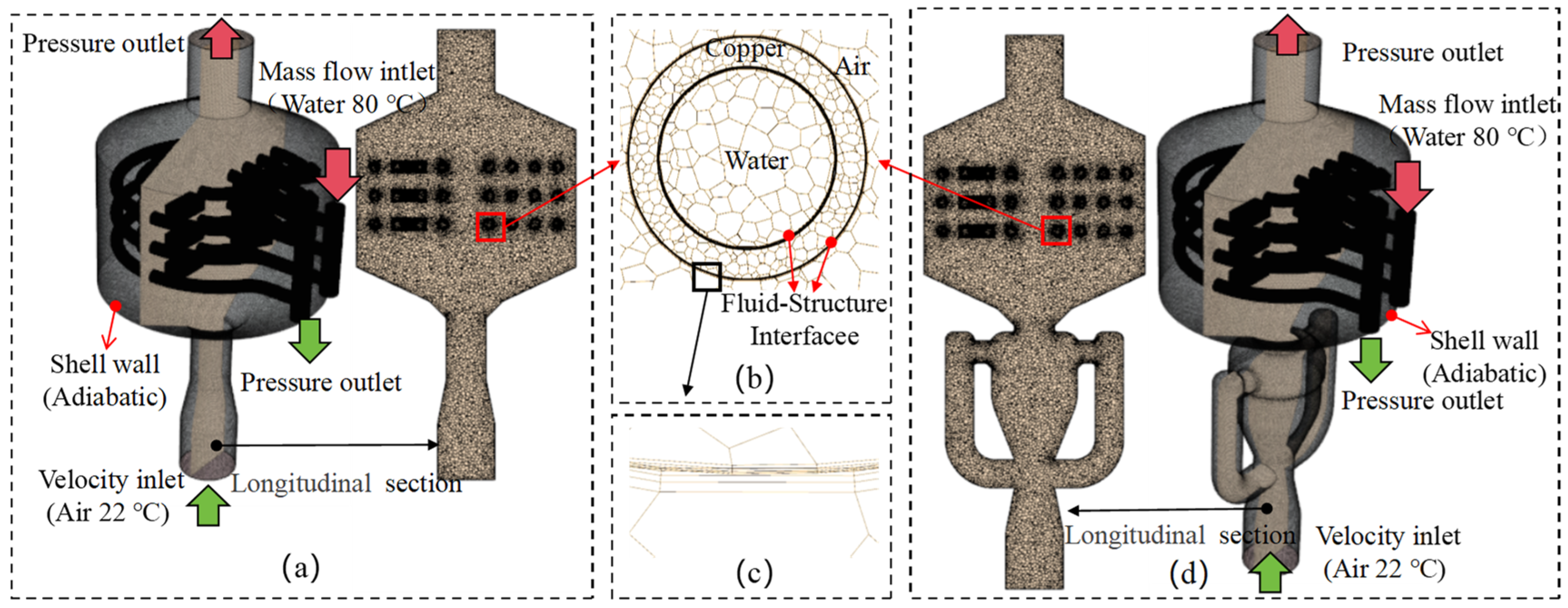
2.2. Numerical Model

This study employs a finite volume method theoretical framework and utilizes Star CCM+ software to construct a three-dimensional numerical model for the numerical simulation of the coupled heat transfer characteristics between the tube side and the shell side of a heat exchanger. The numerical computation process includes the following key steps. First, the computational domain is spatially discretized using polyhedral meshes, which exhibit excellent convergence properties and computational efficiency in complex geometrical structures. Given the dominant role of the near-wall thermal boundary layer effects in convective heat transfer processes, this study employs a progressive boundary layer mesh technique (as illustrated in Figure 2c) to effectively capture the coupled distribution characteristics of the velocity gradient and temperature field by refining the mesh resolution near the wall.
This study found that as the number of boundary layers increased, the CFD results showed minimal variation. Based on an optimization balance between computational accuracy and resource consumption, a total of five boundary layers were determined for both the inner and outer surfaces of the tube wall [33]. The boundary condition configurations strictly adhered to the actual operating conditions of the engineering application: the tube side utilized a mass flow rate inlet boundary (water), while the shell side was set with a velocity inlet condition (air), and both the inlet and outlet employed pressure outlet boundaries (specific boundary settings are illustrated in Figure 2a,d). The numerical model specifically established a fluid–structure interaction (FSI) heat transfer interface to accurately characterize the liquid–solid–gas coupled heat transfer process, while the non-heat transfer surfaces were treated with adiabatic boundary conditions for physical isolation.
The thermodynamic process is characterized by the high-temperature water working fluid in the tube side transferring heat to the tube wall through conduction, which is then dissipated to the cold air on the shell side via convective heat transfer (Figure 2b). The mathematical and physical models of the boundary conditions, along with their numerical implementation methods, will be systematically elaborated in Section 2.4.

2.3. Governing Equations

Continuity equation [33]:
u x + v y + w z = 0
Momentum equation [33]:
ρ u t + u u x + v u y + w u z = p x + μ 2 u x 2 + 2 u y 2 + 2 u z 2
ρ v t + u v x + v v y + w v z = p y + μ 2 v x 2 + 2 v y 2 + 2 v z 2
ρ w t + u w x + v w y + w w z = p z + μ 2 w x 2 + 2 w y 2 + 2 w z 2
Thermal energy equation [33]:
ρ c p T t + u T x + v T y + w T z = λ 2 T x 2 + 2 T y 2 + 2 T z 2
In the three-dimensional fluid dynamics model, the flow characteristics along the x, y, and z axes are represented by the velocity field vectors u, v, and w, respectively. The key physical parameters involved in the governing equations include the fluid static pressure p, density ρ , dynamic viscosity μ , specific heat at constant pressure c p , thermodynamic temperature T, and material thermal conductivity k, with the time dimension described by the independent variable t. The numerical solution of this coupled system of partial differential equations (Equations (1)–(5)) is achieved using the finite volume method solver Star-CCM+, and the computational process strictly adheres to the predefined boundary constraints.

2.4. Boundary Conditions

This study systematically investigates the differences in the multi-field coupled heat transfer characteristics of an elastic tube bundle under fixed operating conditions, comparing the high-temperature water working fluid in the tube side with the cold air in the shell side, both with and without external fluid oscillators. The numerical modeling is constructed based on the following theoretical framework and assumptions:
  • Fluid medium assumptions
    (1)
    The fluid in the tube side (water) and the fluid in the shell side (air) are both treated as incompressible Newtonian fluids with constant physical properties.
    (2)
    Radiative heat transfer and gravitational effects are neglected.
  • Boundary condition settings
    (1)
    Shell-side fluid: A velocity inlet boundary is applied, with a uniform velocity field and a constant temperature of 22 °C.
    (2)
    Tube-side fluid: A mass flow rate inlet boundary is set, with an inlet temperature of 80 °C.
    (3)
    Two-phase outlet: Pressure boundary conditions are applied, with a gauge pressure set to 0 Pa.
  • Multi-field coupling mechanism
    The establishment of the fluid-solid interaction (FSI) heat transfer interface is shown as follows.
    (1)
    Inner wall: water–copper conjugate heat transfer; outer wall: copper–air convective heat transfer.
    (2)
    An adiabatic boundary is applied to the shell wall to eliminate environmental thermal interference.
  • Numerical solution strategy
    (1)
    A numerical simulation framework is constructed based on the RNG k-ε turbulence model, which significantly enhances the prediction accuracy of swirling and separated flows by modifying the eddy viscosity.
    (2)
    The finite volume method is employed to spatially discretize the governing equations (Navier–Stokes equations and energy equation), with pressure–velocity coupling achieved through the SIMPLEC algorithm.
    (3)
    A second-order implicit scheme is used for time advancement, and to balance computational efficiency and accuracy, an optimal time step of Δt = 0.05 s is determined through time step independence verification.
    (4)
    Near-wall treatment employs enhanced wall functions.
Figure 2a,d detail the spatial topology of the boundary conditions, while Table 2 quantifies the complete data set of fluid physical parameters and operating conditions. This study reveals the mechanism of heat transfer enhancement due to self-excited vibrations by comparing key indicators such as the heat transfer power and heat transfer coefficients with and without external self-excited structural elements.

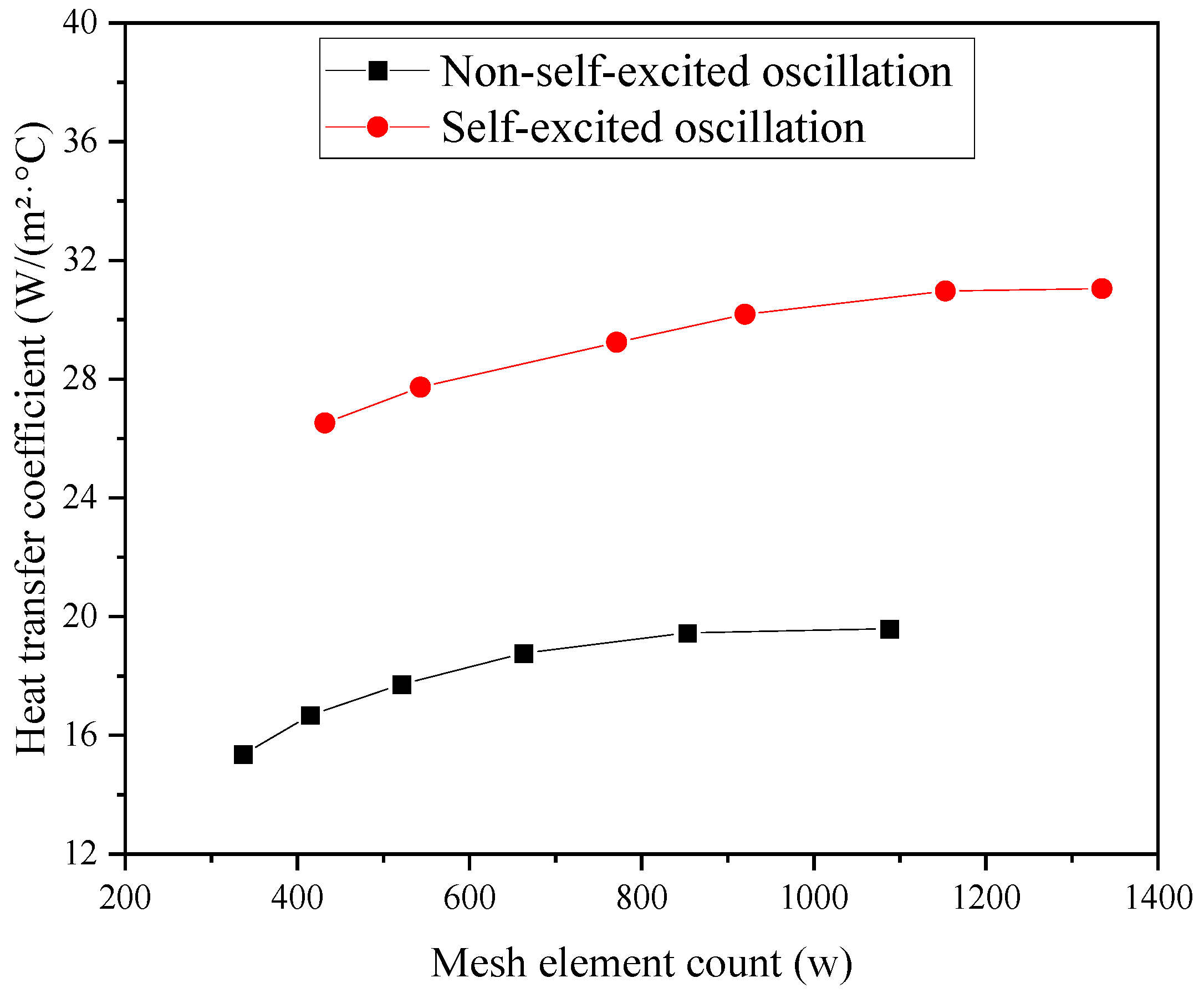
2.5. Mesh Independence Verification

As the grid density increases, the accuracy of the numerical solution tends to improve. Once the grid density reaches a critical threshold, the computational accuracy exhibits an asymptotic convergence characteristic, while the computational resources demonstrate a superlinear growth trend. Therefore, this study determines the optimal grid configuration through a grid independence verification method, ensuring computational efficiency. Based on the residual convergence criterion and stability analysis of the heat transfer coefficient, the final selected grid element count for the computational model of the original structure is 8,531,851, while the model with the fluid oscillator has a grid element count of 11,526,379. These grid systems are adopted as the discretization scheme for the computational domain in the subsequent numerical simulations of convective heat transfer.
Figure 3 presents the results of the grid independence verification. When the number of grid elements exceeds the critical threshold (with the original structure exceeding 8 × 10⁶ and the improved structure exceeding 1.1 × 10⁷), the relative error of the heat transfer coefficient stabilizes within ±0.8%, indicating that the computational results are no longer sensitive to the grid density.

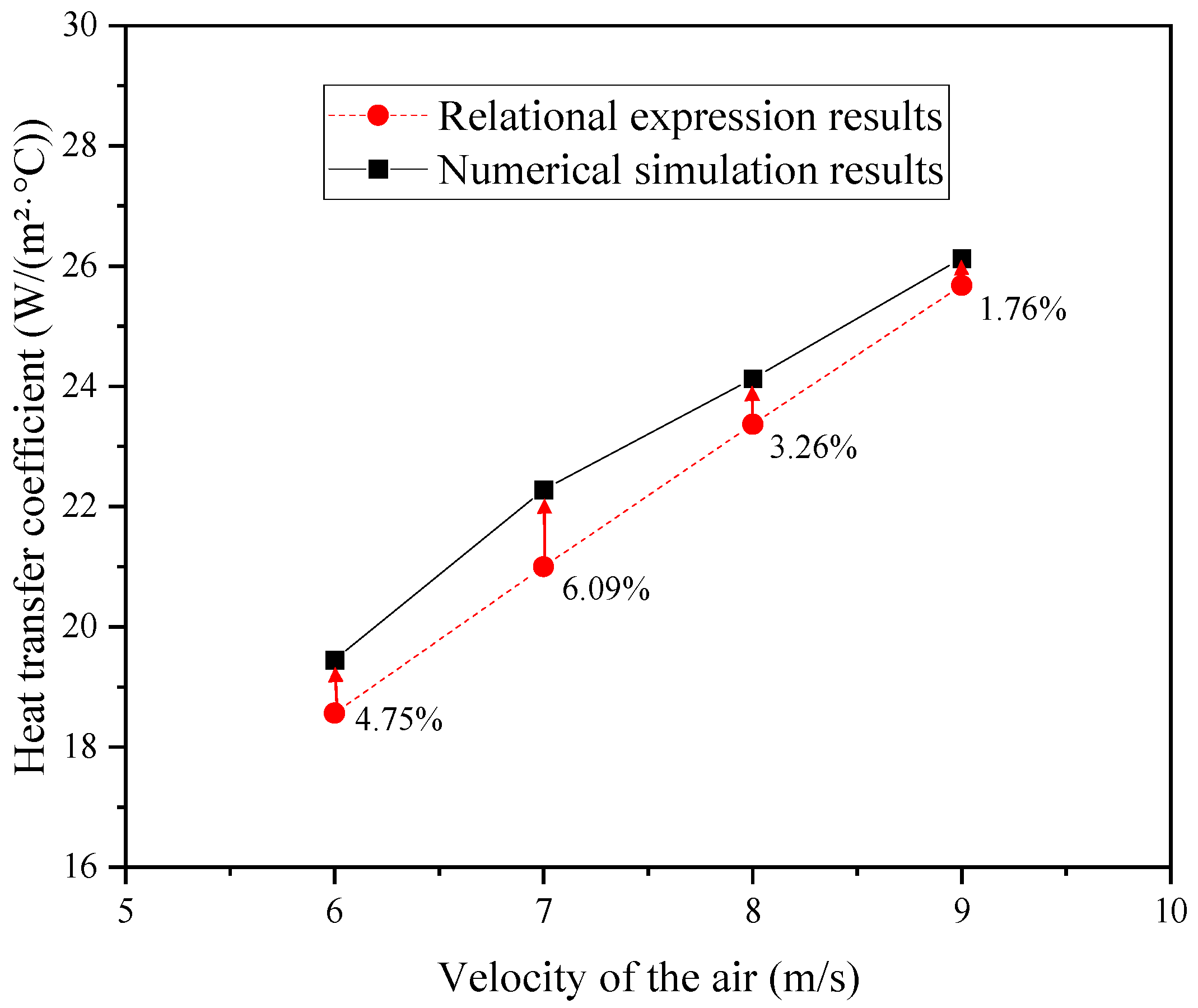
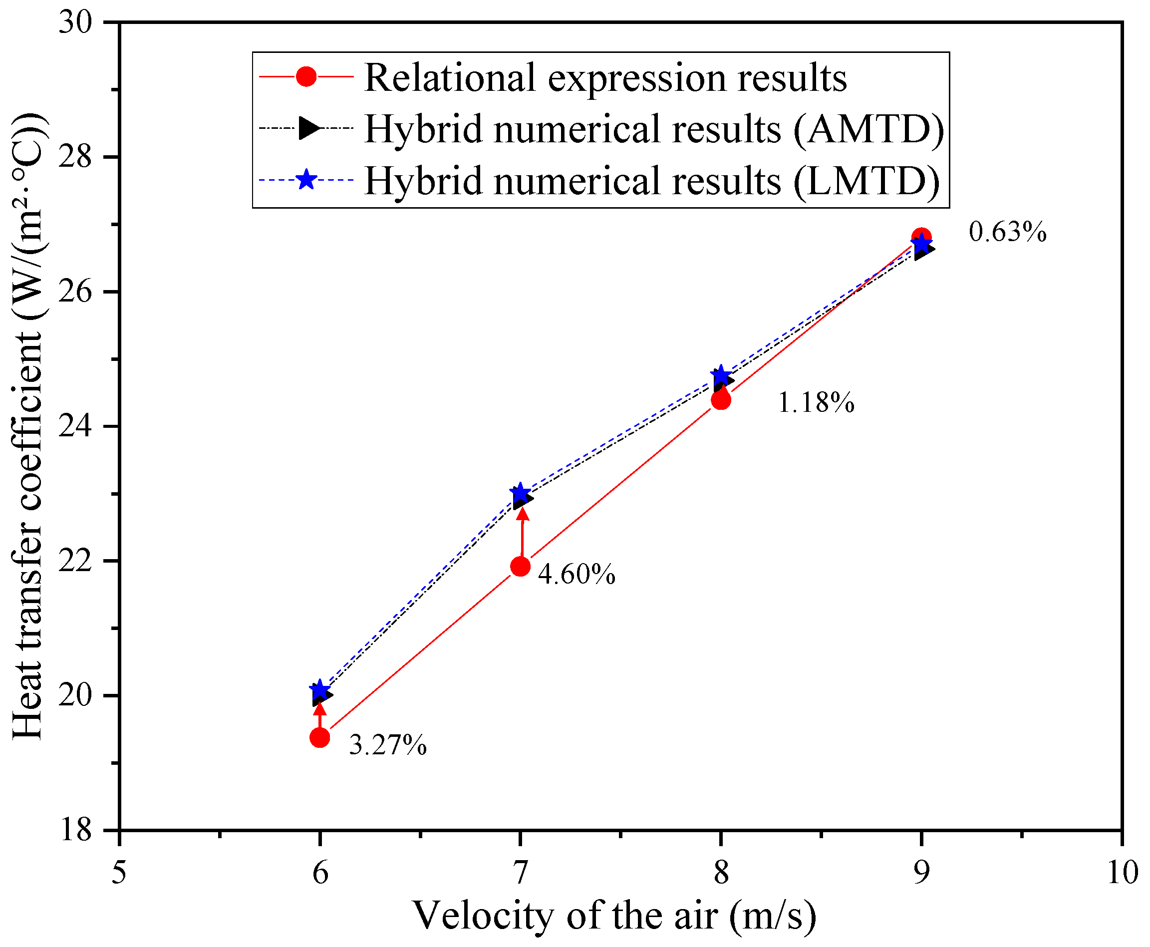
2.6. Numerical Simulation Results Validation

Two distinct methodologies were employed to validate the numerical simulation results.
(1) Methodology I
In this convective heat transfer simulation, key parameters, including the temperature drop amplitude ΔT of the hot water in the tube bundles (for both the original and modified structures), pressure drop ΔP of the cooling air across the shell side, total heat exchange power P, and convective heat transfer coefficient h, were directly extracted from the Star CCM+ simulations.
Given that air exhibits significantly lower specific heat capacity and thermal conductivity compared to water, its volumetric heat exchange capacity as a cooling medium is substantially inferior. Consequently, in elastic tube bundle systems relying predominantly on air-side convective heat dissipation, the overall heat exchange capacity can be approximated as being dominated by the air-side heat transfer process.
The computational procedure for relational results comprises the following steps.
Nu = 0.023 Re0.8Pr0.4
In Equation (6):
Re represent the Reynolds number, defined as R e = ρ v d μ , ρ, μ, and d represent the density, dynamic viscosity, and inner pipe diameter, respectively.
P r represents the Prandtl number, defined as P r = μ C p k , and C p and k represent the specific heat capacity at constant pressure and thermal conductivity, respectively.
Applicability conditions:
The correlation (Equation (6)) is valid for Reynolds numbers Re > 104. In the computational analysis of the heat transfer between elastic tube bundles and air, the calculated Reynolds numbers consistently exceeded 104, thereby confirming the applicability of this correlation for subsequent calculations.
Heat transfer coefficient:
h = N u k d
Substituting the cooling air velocity (6~9 m/s) and the inner diameter d of the shell (0.384 m) into the aforementioned formula (Dittus–Boelter equation), the theoretical convective heat transfer coefficient relationship was derived. The numerical simulation results for the heat transfer coefficient were then exported from the software, with data primarily extracted from the original structure without the fluidic oscillator. A comparative analysis of the theoretical and simulated results is presented in Figure 4 below.
As shown in Figure 4, the maximum deviation between the relational expression results and the numerical simulation outcomes is confined to approximately 6%, demonstrating that the numerical simulation methodology and its results exhibit strong consistency.
(2) Methodology II
The convective heat transfer coefficient was calculated using two temperature difference computation methods: the arithmetic mean temperature difference (AMTD) and the logarithmic mean temperature difference (LMTD). The formulas for the convective heat transfer coefficient and temperature difference are defined as follows [33]:
h = Q / Δ T
The arithmetic mean temperature difference (AMTD) [33]:
T f = T i n + T o u t / 2
Δ T A = T f T w
The logarithmic mean temperature difference (LMTD) [33]:
Δ T L = T i n T o u t l n T i n T W / T o u t T W
In the above equations, h, Q, F, and ΔT represent the convective heat transfer coefficient, total heat exchange power, heat transfer area, and temperature difference, respectively. Tin and Tout denote the inlet and outlet temperatures of the cooling air within the shell, while Tw corresponds to the tube wall temperature. The parameters Q, F, Tw, Tin and Tout were directly extracted from the Star CCM+ simulations. However, the convective heat transfer coefficient was calculated using theoretical formulas, resulting in a hybrid numerical result that integrates simulation data with analytical correlations.
For this validation, simulation data from the original structure were employed. Table 3 provides the numerical values of the aforementioned five parameters obtained from the simulations.
By substituting the simulation data from Table 3 into Equations (8)~(11), the hybrid numerical results for the convective heat transfer coefficient were obtained. Figure 5 illustrates the comparative analysis between these hybrid numerical results and the relational expression results.
As demonstrated in Figure 5, the maximum deviation between the relational expression results and the hybrid numerical results is confined to within 5%, with the outcomes calculated using the AMTD and LMTD showing close agreement.
Synthesizing the validation results from both methodologies reveals that the numerical simulation approach and correlation-derived results exhibit strong consistency. All the subsequent computational results are extracted directly from the Star CCM+ software.

3. Results and Discussion

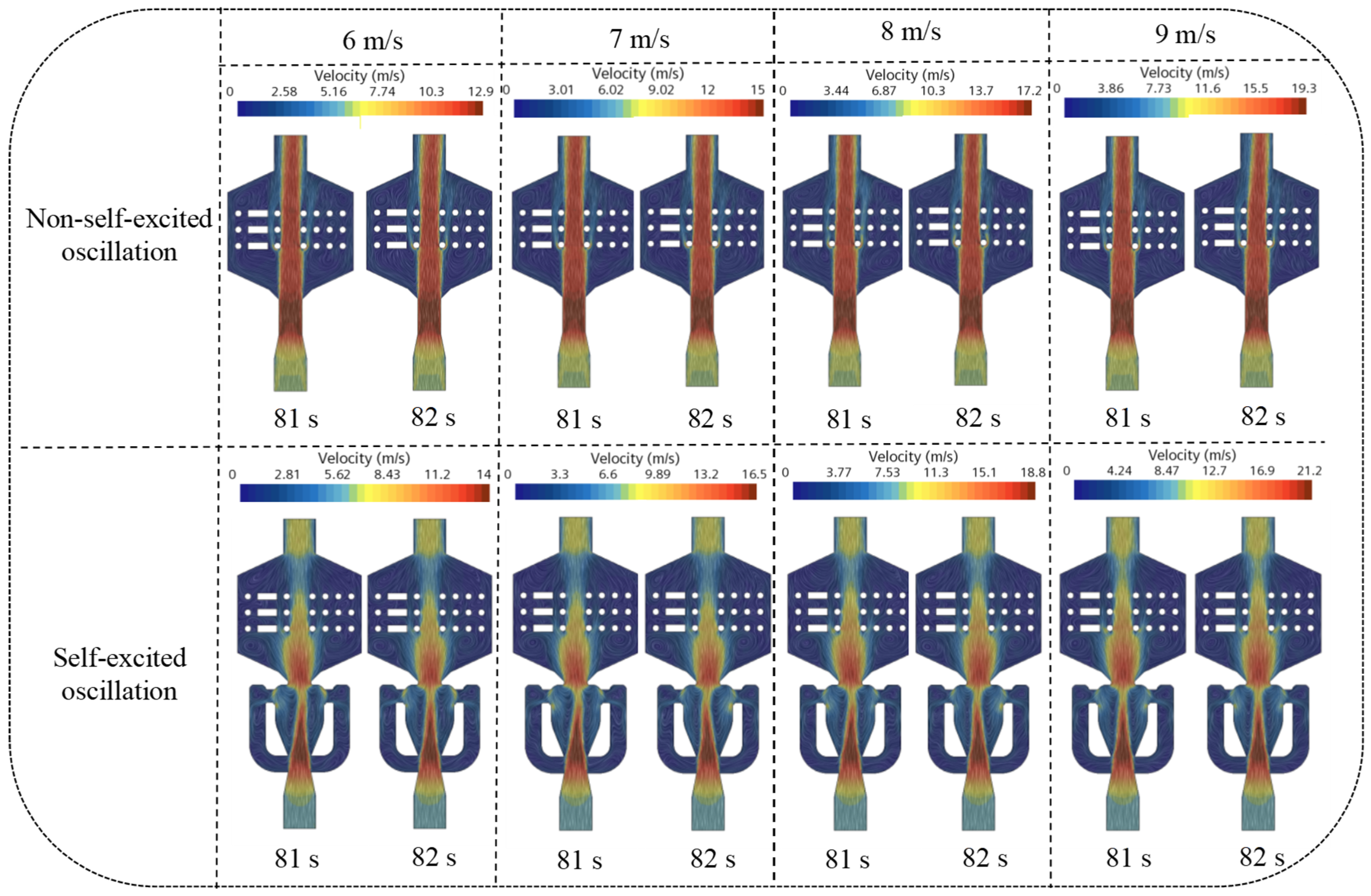
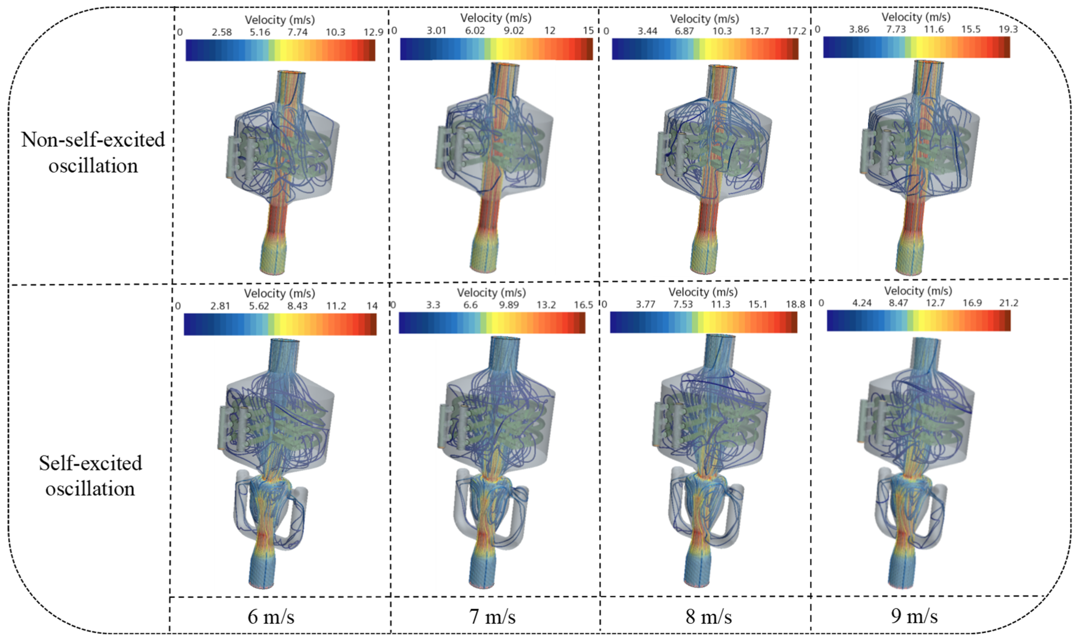
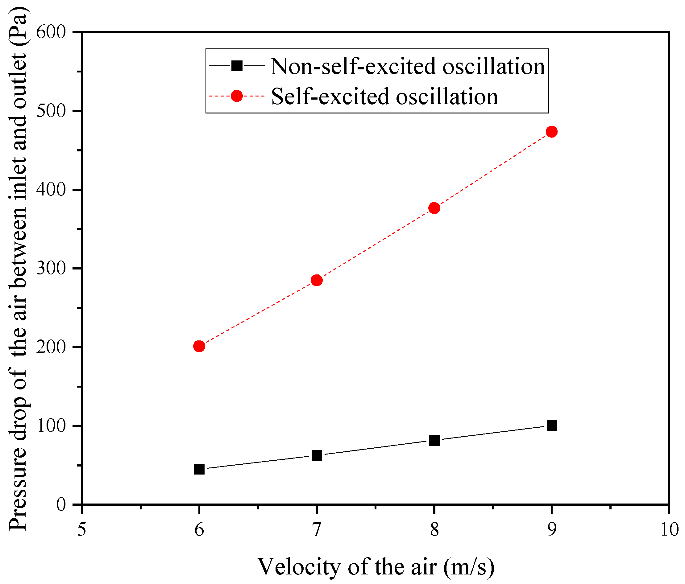
3.1. Flow Characteristics Analysis

Figure 6 presents the velocity distribution contour plots at the mid-section of the original and improved structures of the elastic tube bundle, with the cooling air velocities ranging from 6 to 9 m/s. Figure 7 illustrates the streamline distributions for both structures. Figure 8 shows the relationship between the average turbulent kinetic energy and the velocity of the cold air at the cross-section of the shell side for both configurations. Finally, Figure 9 compares the pressure losses at the inlet and outlet of the cold air in the shell side for the two structures.
From Figure 6, it can be observed that in the original structure, the velocity decay of the flowing cold air in the core region of the shell side is relatively small, exhibiting no periodic lateral oscillations, and the diameter of this region is comparable to the inlet diameter. In contrast, in the improved structure, the velocity decay of the cold air in the core region of the shell side is significantly greater, displaying a periodic oscillatory pattern. Additionally, the diameter of the core region is substantially enlarged. Compared to the original structure, this periodic lateral oscillation facilitates the movement of more cold air into other regions of the shell side, leading to a significant increase in the affected area. Furthermore, this regular periodic oscillation increases the turbulence level of the cold air in the shell side, as shown in Figure 7.
According to the turbulent kinetic energy (TKE) of both structures, the TKE of the cold air in the shell side of the improved structure far exceeds that of the original structure, as illustrated in Figure 8. This periodic oscillation can reduce the boundary layer thickness and thermal resistance, thereby enhancing the heat transfer effect. Unlike the approach of relying on mechanical vibrations to reduce the boundary layer thickness to improve the heat transfer capability, the periodic oscillations of the cold air generated by the fluid oscillator entering the shell side have a minimal impact on the fatigue strength of the tube bundle. However, this structure may result in increased energy losses; as shown in Figure 9, the greater the inlet velocity of the cold air, the faster the increase in the pressure loss. Nonetheless, this also indirectly indicates that the turbulence intensity of the cold air in the regions outside the core area of the shell is greater under the improved structure, leading to more effective heat exchange with the tube bundle. Therefore, the heat transfer effect is theoretically expected to be enhanced.
Next, a comparative analysis of the heat transfer characteristics of the original and improved structures is conducted by quantifying the heat transfer power (P), the heat transfer coefficient (h), and the temperature reduction of the hot water within the tube bundle (∆T) for both configurations.

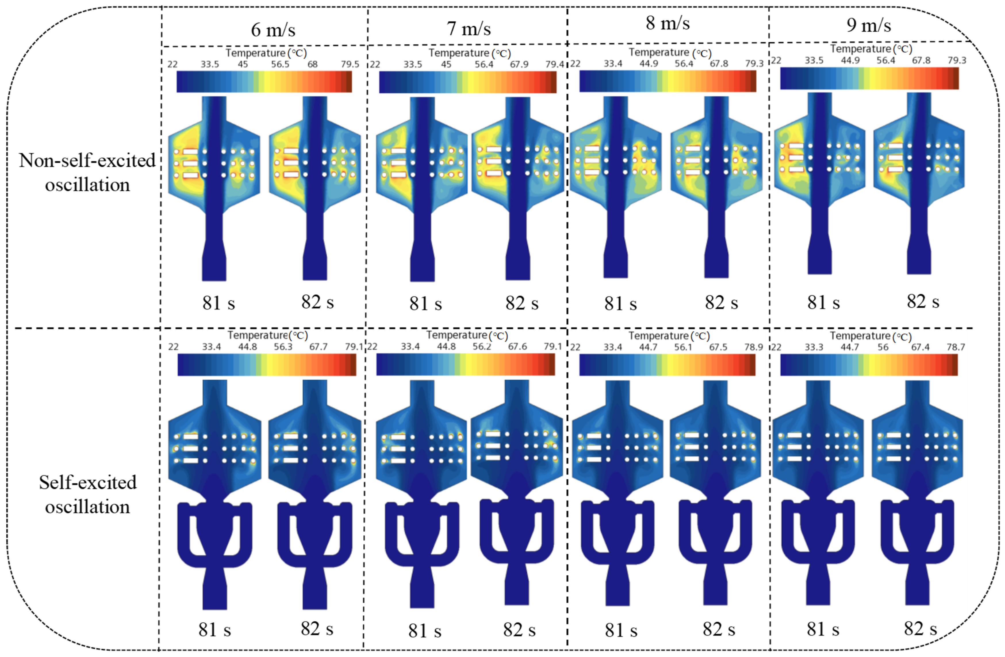
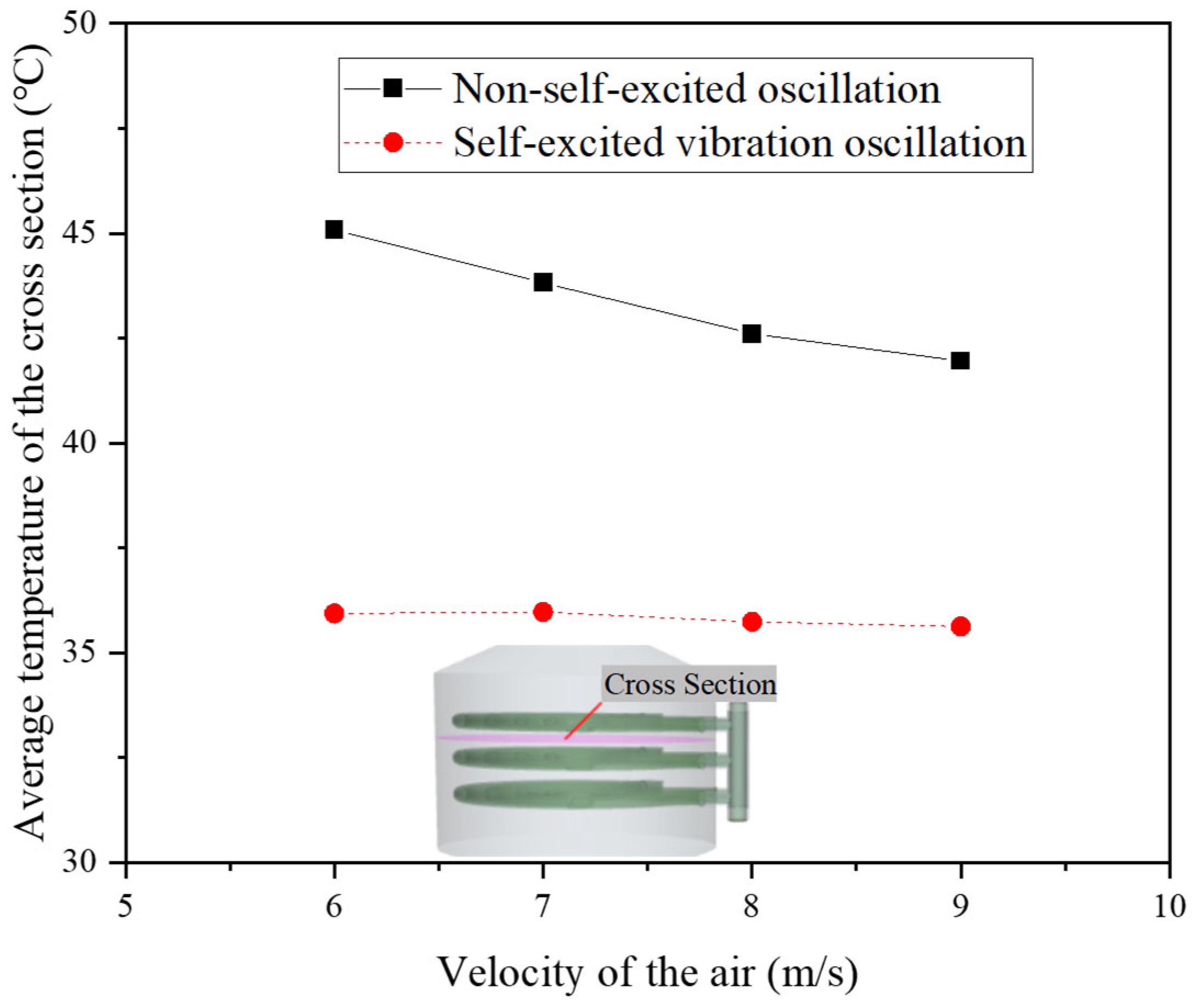
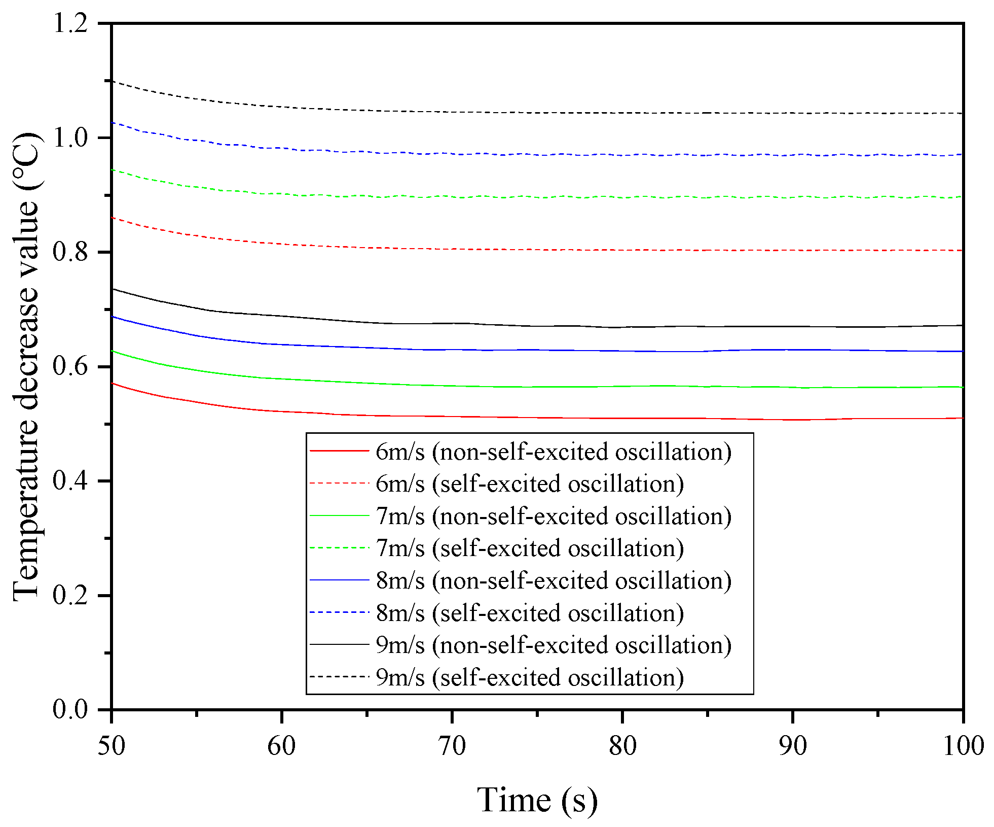
3.2. Effect of Cold Fluid Flow Velocity on Heat Transfer Characteristics

The data presented in this section are based on the premise of a water mass flow rate of 0.2 kg/s in the tube side. Figure 10 illustrates the temperature distribution across the middle longitudinal section of both the original and the improved structures at different cold air inlet velocities. Figure 11 shows the variation of the heat transfer power with the time for both structures under different cold air inlet velocities. Figure 12 also presents the heat transfer power variation with the time for both structures at different cold air inlet velocities. Figure 13 depicts the relationship between the average heat transfer power of the two structures and the cold air inlet velocity. Figure 14 demonstrates the variation of the convective heat transfer coefficient with the time for both structures at different cold air inlet velocities. Finally, Figure 15 presents the change in the temperature reduction of the hot water within the tube bundle over time for both structures at varying cold air inlet velocities. These figures provide valuable insights into the heat exchange performance of the different structures under various operating conditions.
From Figure 10, it can be observed that under the condition of a constant water mass flow rate in the tube side, the temperature decay of the cold air in the core region of the shell side for the original structure is relatively small. This leads to a significant accumulation of high-temperature air in the regions outside the core area, resulting in a smaller temperature difference with the outer surface of the tube bundle, thereby reducing the convective heat transfer capacity. In contrast, in the improved structure, the temperature in the regions outside the core area of the shell is relatively lower compared to the original direct-impingement structure. This indicates a greater temperature difference with the outer surface of the tube bundle, which theoretically enhances the convective heat transfer capacity, as illustrated in Figure 11.
As shown in Figure 12, the periodic fluid oscillation intensity generated by the improved structure is related to the inlet velocity of the cold air. With an increase in the inlet velocity, the oscillation intensity first increases and then decreases. The fundamental reason for this behavior lies in the jet direction switching mechanism based on the Coanda effect, which causes the fluid oscillator to produce periodic unsteady jets. In contrast, the original structure also exhibits irregular oscillations, primarily due to the high velocity of the central jet. When the cold air flows rapidly through the tube bundle in the shell side, it generates a wake that triggers the Kármán vortex street phenomenon. Therefore, the principles underlying the oscillation phenomena in the two structures are distinctly different.
From the perspective of the heat transfer power, the improved structure shows an increase of over 50% compared to the original structure. Specifically, at a cold air inlet velocity of 6 m/s, the heat transfer power of the improved structure is 659.40 W, significantly exceeding the original structure’s 419.85 W, representing an increase of 57.1%. When the cold air inlet velocity reaches 9 m/s, the heat transfer power of the improved structure is 857.26 W, which is a 53.1% increase over the original structure’s 558.26 W.
Figure 13 indicates that the average heat transfer power for both structures increases linearly with the velocity of the cold air in the shell side, although the improved structure is more sensitive to changes in the cold air velocity. Similarly, the convective heat transfer coefficient exhibits a pattern consistent with that of the heat transfer power (as shown in Figure 14). The enhancement of the heat transfer efficiency further increases the magnitude of the temperature reduction of the hot water within the tube side (as illustrated in Figure 15). Quantitatively, at a cold air inlet velocity of 6 m/s, the temperature reduction of the hot water in the improved structure is 0.803 °C, significantly higher than the original structure’s 0.510 °C, representing an increase of 57.4%. At a cold air inlet velocity of 9 m/s, the temperature reduction of the hot water in the improved structure reaches 1.043 °C, which is a 55.2% improvement over the original structure’s 0.672 °C.
Therefore, after analyzing the heat transfer characteristics of the two structures at different velocities of the cooling air in the shell side, it can be concluded that the improved structure exhibits a heat transfer efficiency enhancement of over 50% compared to the original structure due to the periodic oscillations generated by the fluid oscillator. Additionally, there are no issues related to the fatigue strength of the tube bundle. This indicates that the new structure can effectively enhance the heat transfer capacity of shell-and-tube heat exchangers.

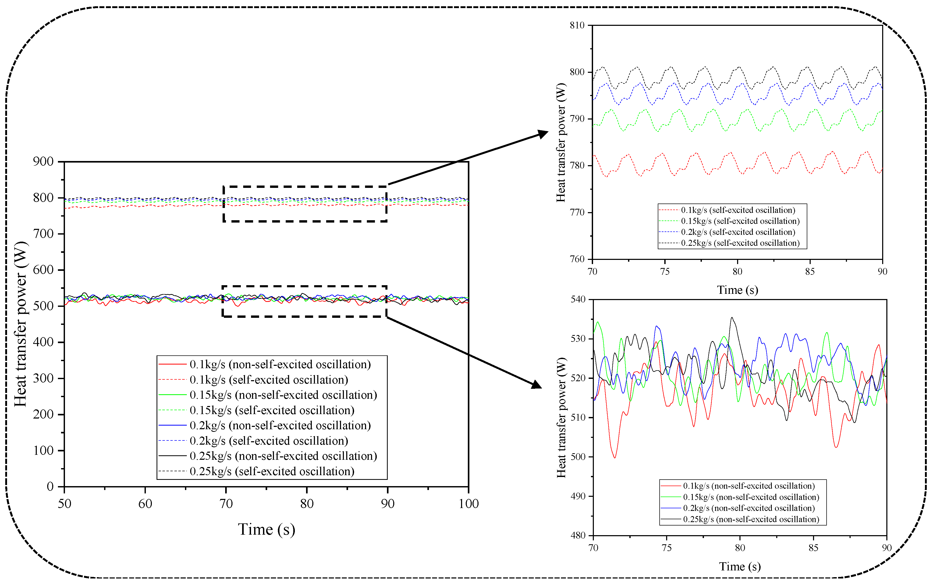
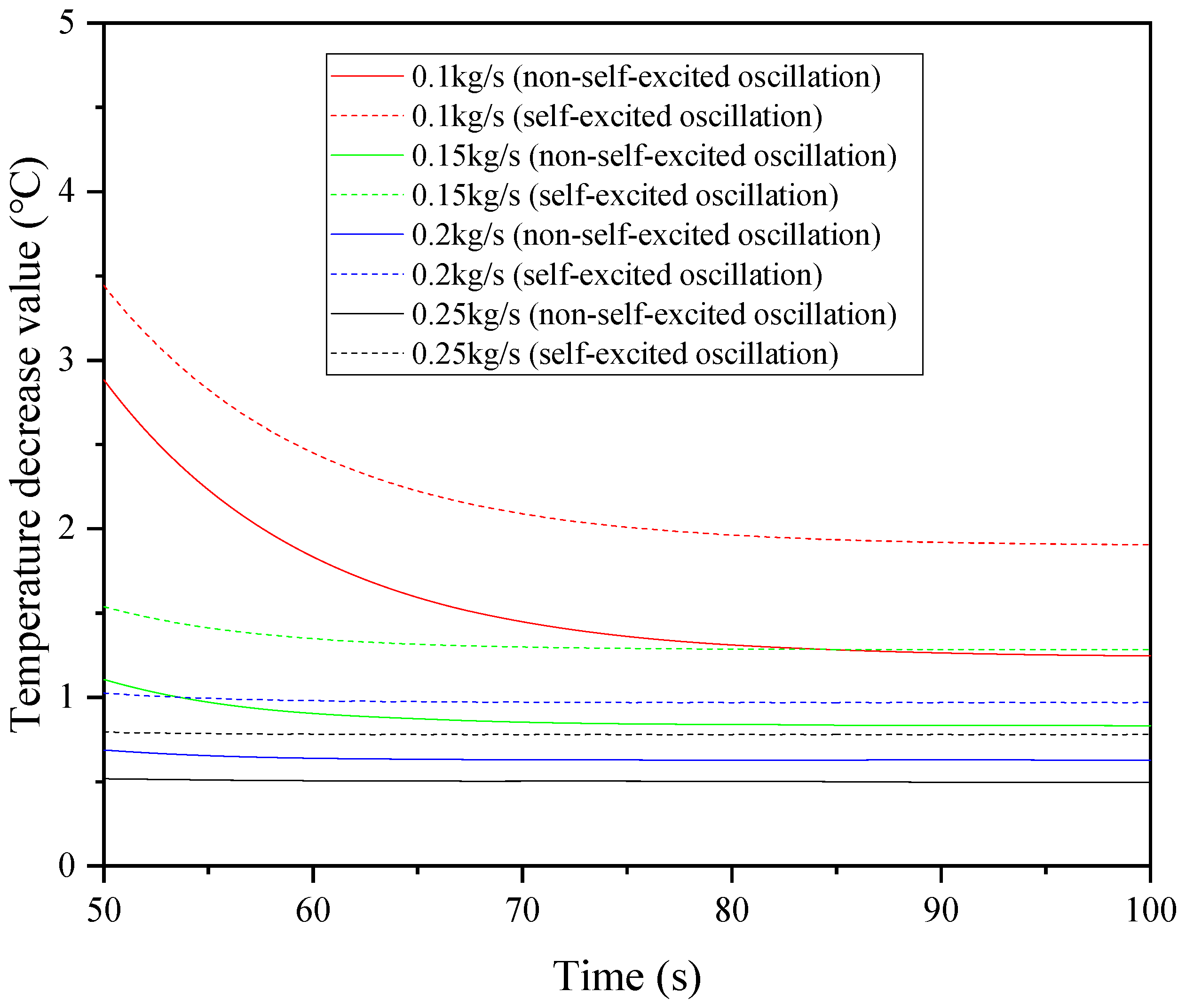
3.3. Influence of Thermal Fluid Flow Rate on Heat Transfer Characteristics

The data presented in this section are based on the assumption that the inlet velocity of the cooling air in the shell side is 8 m/s. Figure 16 illustrates the variation of the heat transfer power with the time for the two different structures under varying mass flow rates of the hot water in the tube side. Figure 17 shows the variation of the convective heat transfer coefficient with the time for the same two structures under different mass flow rates of hot water. Figure 18 depicts the change in the temperature reduction of the hot water within the tube bundle over time for the two structures at varying mass flow rates of hot water.
As shown in Figure 16, under the condition of a constant inlet velocity of cooling air in the shell side, the intensity of the periodic fluid oscillations generated by the improved structure exhibits no significant change with the increasing mass flow rates of the hot water in the tube side. However, the heat transfer power gradually increases with the mass flow rate of the hot water. Specifically, at a mass flow rate of 0.1 kg/s, the heat transfer power is 781.31 W, which represents an increase of 2.18% compared to 798.36 W at 0.25 kg/s, although this increase is not substantial. This increase in the heat transfer power due to the higher mass flow rate in the pipeline can be attributed to two main reasons: first, the increase in the fluid velocity reduces the thermal resistance by thinning the temperature boundary layer, allowing heat to transfer more rapidly through the boundary layer into the fluid core; and second, as indicated by Equations (6) and (7), the Nusselt number and heat transfer coefficient increase with the Reynolds number. In contrast, the original structure shows no significant change in the oscillation intensity or heat transfer power with the increasing flow rate of the hot water. Numerically, the heat transfer power of the improved structure is at least 50.6% higher than that of the original structure (increasing from 518.74 W to 781.31 W at 0.1 kg/s).
Similarly, with regard to the heat transfer coefficient, the two structures exhibit the same trend as the heat transfer power (as shown in Figure 17). For both structures, the effect of different mass flow rates of the hot water in the tube side on the heat transfer capability is not significant, indicating that if the flow rate of the hot water in the tube side is relatively low, the heat removal will be approximately the same, which inevitably leads to an increase in the temperature difference between the inlet and outlet (as shown in Figure 18). Figure 18 also reveals that the temperature reduction of the improved structure is greater than that of the original structure, indicating that the heat transfer efficiency of the new structure is superior to that of the original. For both structures, the magnitude of the temperature reduction at the inlet and outlet decreases as the mass flow rate of the hot water in the tube side increases. Numerically, at a mass flow rate of 0.1 kg/s, the temperature reduction of the improved structure is 1.91 °C, significantly exceeding the 0.78 °C observed at 0.25 kg/s; compared to the original structure, the temperature reduction of the improved structure has increased by over 50%. Specifically, at a mass flow rate of 0.1 kg/s, the temperature reduction of the improved structure is 1.91 °C, which is a 52.8% increase over the original structure’s 1.25 °C, and at 0.25 kg/s, the improvement is 57.1%.
Therefore, the analysis of the heat transfer characteristics of the two structures at different mass flow rates of the hot water in the tube side reveals that, compared to the original structure, the improved structure enhances the heat transfer efficiency by more than 50% due to the periodic oscillations generated by the fluid oscillator, without compromising the fatigue strength of the tube bundle. This further demonstrates that a shell-and-tube heat exchanger equipped with a fluid oscillator can still effectively enhance the heat transfer capability while the tube bundle remains fixed.

4. Conclusions

This study systematically investigates the enhancement mechanism of the heat transfer performance in elastic tube bundle heat exchangers due to external fluid self-excited oscillations through numerical simulations and theoretical analyses. The main conclusions are as follows.
(1) Enhanced heat transfer efficiency. The improved structure equipped with a self-excited fluid oscillator significantly increases the turbulence intensity and radial mixing capability of the cold air in the shell side through a periodic jet switching mechanism, surpassing the heat transfer limits of steady-state flow and achieving at least a 50% enhancement in heat transfer capacity.
(2) Dynamic stress suppression. External fluid self-excited oscillations mitigate the mechanical vibration energy through a non-contact energy transfer system, ensuring that the stress levels in the tube bundle remain below the fatigue threshold, thereby addressing the fatigue failure issues associated with traditional active vibration strategies.
(3) Parameter sensitivity analysis. The heat transfer efficiency of the improved structure is sensitive to the velocity of the cooling air in the shell side, with the heat transfer power increasing linearly with the flow velocity. In contrast, the response to changes in the mass flow rate of the hot water in the tube side is relatively weak, indicating that optimization efforts should focus on regulating the flow field in the shell side.
(4) Engineering applicability. The improved structure achieves enhanced heat transfer without the need for mechanical vibrations in the tube bundle, characterized by simplicity and high reliability, thus providing new insights for the design of industrial heat exchangers. Future research could further explore the synergistic optimization of the oscillation frequency, geometric configuration, and multi-field coupling mechanisms to promote the large-scale application of this technology.
(5) This study validates the feasibility of external fluid self-excited oscillations in the field of heat transfer enhancement, providing theoretical foundations and technical support for the efficient and safe operation of heat exchange equipment under high thermal flux conditions.

Author Contributions

J.H.: Writing—original draft, investigation, data curation, conceptualization, software. L.G.: Resources, validation, funding acquisition, writing—review and editing. S.Z.: Theoretical guidance, writing—review and editing. All authors have read and agreed to the published version of the manuscript.

Funding

This program was supported by the 2023 Natural Science Foundation of Hunan Province [No. 2023JJ50452], the 2024 Natural Science Foundation of Hunan Province [No. 2024JJ7379], and the Key Laboratory of Intelligent Control Technology for Wuling-Mountain Ecological Agriculture in Hunan Province [No. ZNKZN2021-06, No. ZNKZD2023-5]. And The APC was funded by [No. 2023JJ50452].

Data Availability Statement

The data that support the findings of this study are available from the corresponding author upon reasonable request.

Conflicts of Interest

The authors declare no competing interests.

References

  1. Karabacak, R.; Yakar, G. Forced convection heat transfer and pressure drop for a horizontal cylinder with vertically attached imperforate and perforated circular fins. Energy Convers. Manag. 2011, 52, 2785–2793. [Google Scholar] [CrossRef]
  2. Dong, P.C.; Jia, Y.X.; Xie, G.N.; Ni, M. The energy performance improvement of a PEM fuel cell with various chaotic flowing channels. Int. J. Energy Res. 2019, 43, 5460–5478. [Google Scholar] [CrossRef]
  3. Wang, C.; Gao, P.; Wang, S.; Li, X.; Fang, C. Experimental study of single-phase forced circulation heat transfer in circular pipe under rolling motion. Nucl. Eng. Des. 2013, 265, 348–355. [Google Scholar] [CrossRef]
  4. Tan, L.; Zhang, J.Z.; Tan, X.M. Numerical investigation of convective heat transfer on a vertical surface due to resonating cantilever beam. Int. J. Therm. Sci. 2014, 80, 93–107. [Google Scholar]
  5. Cheng, L.; Luan, T.; Du, W.; Xu, M. Heat transfer enhancement by flow-induced vibration in heat exchangers. Int. J. Heat Mass Transf. 2009, 52, 1053–1057. [Google Scholar] [CrossRef]
  6. Ji, J.; Zhang, J.; Gao, R.; Shi, B.; Li, X.; Li, F.; Deng, X. Numerical Research on Vibration-Enhanced Heat Transfer of Elastic Scroll Tube Bundle. J. Thermophys. Heat Transf. 2022, 36, 61–68. [Google Scholar] [CrossRef]
  7. Ji, J.; Gao, R.; Shi, B.; Zhang, J.; Li, F.; Deng, X. Improved tube structure and segmental baffle to enhance heat transfer performance of elastic tube bundle heat exchanger. Appl. Therm. Eng. 2022, 200, 117703. [Google Scholar] [CrossRef]
  8. Ji, J.; Zhang, J.; Li, F.; Chen, Q.; Ni, X.; Deng, X. Numerical research on vibration-enhanced heat transfer of improved elastic tube bundle heat exchanger. Case Stud. Therm. Eng. 2022, 33, 101936. [Google Scholar] [CrossRef]
  9. Ji, J.; Pan, Y.; Deng, X.; Zhang, J.; Liu, P. Research on the heat transfer performance of an improved elastic tube bundle heat exchanger under fluid-induced vibration. Case Stud. Therm. Eng. 2023, 49, 103184. [Google Scholar] [CrossRef]
  10. Su, Y.; Li, M.; Miao, X.; Lv, Y.; Bi, J. Research on enhancement of heat transfer by vortex-induced vibration of heat exchange tube bundles with elastic joints. Numer. Heat Transf. Part A Appl. 2022, 82, 543–560. [Google Scholar] [CrossRef]
  11. Sukhotski, A.B.; Danil’chik, S. Convective Heat Exchange of Single-Row Bundles from Tubes with Rolled Aluminum Fins of Various Height at A Low Values of The Reynolds Number. Energ. Proc. CIS High. Educ. 2021, 64, 336–348. [Google Scholar] [CrossRef]
  12. Ding, Z.; Bai, X.; Zhai, Y.; Yang, J.; Liu, D.; Yang, Y.; Tang, D. Numerical Simulation Research on the Vibration of Helical Tube Arrays under Transverse Flow. Energies 2022, 15, 9082. [Google Scholar] [CrossRef]
  13. Khushnood, S.; Khan, Z.M.; Malik, M.A.; Koreshi, Z.; Khan, M.A. Modeling and Simulation of Cross-Flow Induced Vibration in a Multi-Span Tube Bundle. In Proceedings of the 12th International Conference on Nuclear Engineering, Arlington, VA, USA, 25–29 April 2004. [Google Scholar]
  14. Arani, A.A.A.; Uosofvand, H. Double-pass shell-and-tube heat exchanger performance enhancement with new combined baffle and elliptical tube bundle arrangement. Int. J. Therm. Sci. 2021, 167, 106999. [Google Scholar] [CrossRef]
  15. Blaszczuk, A.; Jagodzik, S. Investigation of Heat Transfer in a Large-Scale External Heat Exchanger with Horizontal Smooth Tube Bundle. Energies 2021, 14, 5553. [Google Scholar] [CrossRef]
  16. Chen, L.; Zhang, H.; Huang, S.; Wang, B.; Zhang, C. Numerical Analysis of Flow-Induced Vibration of Heat Exchanger Tube Bundles Based on Fluid-Structure Coupling Dynamics. Model. Simul. Eng. 2022, 2022, 1467019. [Google Scholar]
  17. Ji, J.; Pan, Y.; Zhang, J.; Shi, B.; Bao, L. Numerical study on the effect of baffle structure on the heat transfer performance of elastic tube bundle heat exchanger. Appl. Therm. Eng. 2024, 238, 122220. [Google Scholar] [CrossRef]
  18. Ji, J.; Ge, P.; Bi, W. Numerical analysis on shell-side flow-induced vibration and heat transfer characteristics of elastic tube bundle in heat exchanger. Appl. Therm. Eng. 2016, 107, 544–551. [Google Scholar] [CrossRef]
  19. Ji, J.-D.; Ge, P.-Q.; Bi, W.-B. Numerical analysis of shell-side flow-induced vibration of elastic tube bundle in heat exchanger. J. Hydrodyn. 2018, 30, 249–257. [Google Scholar] [CrossRef]
  20. Yan, K.L.; Ge, P.Q.; Bi, W.B. Study on vibration characteristic and stress intensity of planar elastic tube bundles. Mater. Sci. Forum 2009, 628–629, 227–232. [Google Scholar] [CrossRef]
  21. Duan, D.-R.; Ge, P.-Q.; Bi, W.-B.; Dong, Y.-Y. Vibration Response and Stress Analysis of Planar Elastic Tube Bundle Induced by Fluid Flow. Chin. J. Mech. Eng. 2018, 2, 89–96. [Google Scholar] [CrossRef]
  22. Liu, L.; Xu, W.; Guo, K.; Jia, Z.; Wang, Y.; Tan, W. The fluid elastic instability of concentric arrays of tube bundles subjected on cross flow. In Proceedings of the American Society of Mechanical Engineers, Pressure Vessels and Piping Division (Publication) PVP, Prague, Czech Republic, 15–20 July 2018; Volume 4. [Google Scholar]
  23. Ming, T.; Wang, Z.; Liao, X.; Shi, T.; Tan, G.; Wu, Y. Unsteady RANS simulation of fluid dynamic and heat transfer in an oblique self-oscillating fluidic oscillator array. Int. J. Heat Mass Transf. 2021, 177, 121515. [Google Scholar] [CrossRef]
  24. Kong, X.; Zhang, Y.; Li, G.; Lu, X.; Zhu, J.; Xu, J. Numerical Simulation of the Flow and Heat Transfer Characteristics of Sweeping and Direct Jets on a Flat Plate with Film Holes. Energies 2022, 15, 4470. [Google Scholar] [CrossRef]
  25. Tu, T.; Chen, S.; Shi, Y.; Li, W. Flow mechanism and heat transfer characteristic of sweeping jet impinging on confined concave surfaces. Phys. Fluids 2023, 35, 015147. [Google Scholar] [CrossRef]
  26. Abdelmaksoud, R.; Wang, T. Computational Analysis of Air/Mist Film Cooling Using a Sweeping Jet Fluidic Oscillator–Part I: Sweeping Air-Only Jet With Detailed Analysis of Vortex Dynamics. J. Therm. Sci. Eng. Appl. 2023, 15, 081006. [Google Scholar] [CrossRef]
  27. Hadipour, A.; Zargarabadi, M. Heat transfer enhancement in array of impinging jets by a row of pin-fins on dead fluid zone. J. Taiwan Inst. Chem. Eng. 2023, 148, 104842. [Google Scholar] [CrossRef]
  28. Rezaei, M.; Nili-Ahmadabadi, M.; Tavakoli, M.; Joulaei, A.; Ha, M.Y. Heat transfer enhancement on a concave surface using sweeping impinging jets: Comparison of vortex-based and conventional oscillators. Case Stud. Therm. Eng. 2024, 60, 104738. [Google Scholar] [CrossRef]
  29. Li, X.; Li, J.; Chen, W.; Zhang, J.; Wu, B. Evolution of flow structure and heat transfer enhancement mechanism in impinging jets excited by piezoelectric fan. Int. J. Heat Mass Transf. 2024, 228, 125631. [Google Scholar] [CrossRef]
  30. Lakehal, A.; Aksouh, M.; Medelfef, A. Numerical Study of the Compressible Air Flow Through a Two-output Fluidic Oscillator. J. Appl. Fluid Mech. 2025, 18, 880–891. [Google Scholar]
  31. Liu, G.; Bie, H.; Hao, Z.; Wang, Y.; Ren, W.; Hua, Z. Microbubble generation driven by the oscillation in a self-excited fluidic oscillator. AIChE J. 2022, 68, e17428. [Google Scholar] [CrossRef]
  32. Kaewchoothong, N.; Nuntadusit, C.; Chatpun, S. Effect of Jet-to-Target Spacing on Flow and Heat Transfer Characteristics for Swirling Impinging Micro-Slot Jets. Heat Transf. Eng. 2024, 1–14. [Google Scholar] [CrossRef]
  33. Duan, D.; Ge, P.; Bi, W. Numerical investigation of heat transfer characteristic of fixed planar elastic tube bundles. Energy Convers. Manag. 2015, 103, 859–870. [Google Scholar] [CrossRef]
Figure 1. Geometric configurations of the heat exchanger: (a) original structure, (b) planar tube bundle, (c) fluidic oscillator, and (d) improved structure. The green arrow represents the flow direction of the cold fluid; The red arrow represents the flow direction of the hot fluid.
Fluids 10 00122 g001
Figure 2. Mesh models and key boundary conditions: (a) original structural body mesh and mid-plane mesh model, (b) locally magnified mesh model, (c) boundary layer, and (d) improved structural body mesh and mid-plane mesh model.
Fluids 10 00122 g002
Figure 3. Mesh independence verification.
Fluids 10 00122 g003
Figure 4. Comparison of the heat transfer coefficient values between the relational expression and the numerical simulation.
Fluids 10 00122 g004
Figure 5. Comparison of the heat transfer coefficient values between the relational expression and the hybrid numerical simulation.
Fluids 10 00122 g005
Figure 6. Velocity distribution at the mid-longitudinal section of the two structures under different air inlet velocities.
Fluids 10 00122 g006
Figure 7. Streamline distribution of the two structures under different air inlet velocities.
Fluids 10 00122 g007
Figure 8. Relationship between the velocity of cold air in the shell side of the two structures and the average turbulent kinetic energy (TKE) across the cross-section.
Fluids 10 00122 g008
Figure 9. Pressure loss at the inlet and outlet of cold air in the shell side.
Fluids 10 00122 g009
Figure 10. The temperature distribution across the cross-section of the two structures at different inlet velocities of the cold air in the shell side.
Fluids 10 00122 g010
Figure 11. The cross-sectional average temperature distribution of the two structures under different inlet velocities of the cooling air in the shell side.
Fluids 10 00122 g011
Figure 12. The variation of the heat transfer power with the time for the two structures at different inlet velocities of the cooling air in the shell side.
Fluids 10 00122 g012
Figure 13. The relationship between the average heat transfer power of the two structures and the inlet velocity of the cooling air in the shell side.
Fluids 10 00122 g013
Figure 14. The variation of the heat transfer coefficient with the time for the two structures at different inlet velocities of the cooling air in the shell side.
Fluids 10 00122 g014
Figure 15. The variation of the temperature reduction of the hot water within the tube bundle over time for the two structures at different inlet velocities of the cooling air in the shell side.
Fluids 10 00122 g015
Figure 16. The variation of the heat transfer power with the time for the two structures at different mass flow rates of the hot water in the tube side.
Fluids 10 00122 g016
Figure 17. The variation of the heat transfer coefficient with the time for the two structures at different mass flow rates of the hot water in the tube side.
Fluids 10 00122 g017
Figure 18. The variation of the hot water temperature reduction with the time for the two structures at different mass flow rates of the hot water in the tube side.
Fluids 10 00122 g018
Table 1. The geometry of the planar fixed tube bundles and specific parameters used in the present work.
ParameterValue
Curvature radius R1 × R2 × R3 × R440 mm × 80 mm × 120 mm × 160 mm
Cross-section radius ri × ro15 mm × 20 mm
Mass block dimensions L × W × H62 mm × 30 mm × 22 mm
The length of shell-side Hs240 mm
Copper density ρ c894 kg/m3
Copper thermal conductivity398 W/(m·K)
Copper specific heat386 J/(kg·K)
Table 2. The boundary conditions and physical parameters of the fluid used in the simulation.
ParameterTube Inside (Water)Tube Outside (Air)
Inlet (Uin)0.15~0.25 kg/s6~9 m/s
Pressure outlet Pout0 Pa0 Pa
Inlet temperature Tin80 °C22 °C
Heat transfer area F0.3133 m20.4065 m2
Fluid density ρ 997.56 kg/m31.18415 kg/m3
Specific heat at constant pressure c p 4181.72 J/(kg·K)1003.62 J/(kg·K)
Thermal conductivity k0.6203 W/(m·K)0.02603 W/(m·K)
Dynamic viscosity μ 8.8871 × 10⁻⁴ Pa·s1.855 × 10−5 Pa·s
Table 3. Computational simulation data (non-self-excited oscillation).
The Velocity of the Air Inlet6 m/s7 m/s8 m/s9 m/s
Heat transfer power Q418.7 W478.9 W517.13 W558.68 W
Average external tube wall temperature TW78.72 °C78.50 °C78.41 °C78.29 °C
Temperature of the air inlet T i n 22 °C22 °C22 °C22 °C
Temperature of the air inlet T o u t 32.49 °C32.23 °C31.72 °C31.36 °C
Disclaimer/Publisher’s Note: The statements, opinions and data contained in all publications are solely those of the individual author(s) and contributor(s) and not of MDPI and/or the editor(s). MDPI and/or the editor(s) disclaim responsibility for any injury to people or property resulting from any ideas, methods, instructions or products referred to in the content.

