Review

A Review of Oscillators in Hydrokinetic Energy Harnessing Through Vortex-Induced Vibrations

1
Department of Hydraulic Engineering, Tongji University, 1239 Siping Road, Shanghai 200092, China
2
Faculty of Science, Agriculture and Engineering, Newcastle University, Newcastle upon Tyne NE1 7RU, UK
3
Department of Ocean Engineering and Naval Architecture, Indian Institute of Technology, Kharagpur 721302, West Bengal, India
4
Honeyloop Technologies, Visakhapatnam 531082, Andhra Pradesh, India
5
Department of Aerospace Engineering, Indian Institute of Technology, Kharagpur 721302, West Bengal, India
6
School of Engineering, University of Aberdeen, Aberdeen AB24 3UE, UK
*
Author to whom correspondence should be addressed.
Fluids 2025, 10(4), 78; https://doi.org/10.3390/fluids10040078
Submission received: 14 January 2025 / Revised: 15 March 2025 / Accepted: 17 March 2025 / Published: 24 March 2025
(This article belongs to the Special Issue Marine Hydrodynamics: Theory and Application)

Abstract

:
This review investigates the role of vortex-induced vibrations (VIVs) in hydrokinetic energy harnessing, shedding light on their dual nature as both a challenge in offshore engineering and an untapped resource for renewable energy. VIVs serve as a novel energy source, converting the kinetic energy of fluid flows into mechanical or electrical power. The review discusses the various energy conversion mechanisms, highlighting the unique benefits and challenges of electromagnetic, piezoelectric, and triboelectric systems. A significant emphasis is placed on optimizing VIV energy harnessing to balance maximizing energy output while maintaining structural stability. The review provides insights into the geometric configurations, material properties, and advanced computational methods that are pivotal in this optimisation process. In conclusion, this review provides a comprehensive analysis of the current progress and persistent challenges in VIV research, offering actionable insights and innovative solutions that will advance the field of efficient and sustainable energy.

1. Introduction

In the field of fluid mechanics, Flow-Induced Vibration (FIV) is a phenomenon that has garnered significant attention due to its widespread occurrence and substantial impact on engineering structures. FIV refers to the vibrations induced in structures when subjected to fluid flow, which can lead to beneficial and detrimental effects. The classification of FIV is crucial for understanding its underlying mechanisms and developing effective mitigation or utilisation strategies.
FIV can be broadly categorized into four main types as shown in Figure 1, namely, Vortex-Induced Vibration (VIV), galloping, flutter, and buffeting. VIV is a common fluid–solid coupling phenomenon that occurs when a bluff body in a fluid flow induces periodic vortex shedding, generating fluctuating forces on the structure and resulting in oscillations. Galloping is a self–excited vibration phenomenon typically occurring in long, flexible structures with edges and corners, characterized by low–frequency and high-amplitude oscillations. Flutter is a self–sustained oscillation that can emerge within fluid–structure interaction systems, often involving vortex shedding due to the dynamic interplay with the solid’s geometry. Buffeting refers to periodic vibrations induced by upstream wakes or inherent turbulence, typically occurring in unstable flow environments.
Among these types, VIV is a well-known FIV phenomenon that has been extensively studied over the last few decades. These vibrations arise when a bluff body in a fluid flow induces periodic vortex shedding, generating fluctuating forces on the structure, resulting in oscillations [2,3,4]. VIVs are particularly important in offshore engineering as they impact the design and operational integrity of key structures such as subsea pipelines, cables, and risers connecting offshore platforms to seabed systems [5]. If not properly addressed, vibration can cause material fatigue and eventually lead to the failure of these critical components, posing substantial challenges to the safety and longevity of offshore infrastructures. For example, a subsea pipeline in the North Sea suffered severe fatigue damage due to VIV, resulting in multiple cracks within 18 months and repair costs of approximately USD 1.5 million [6]. Another case is a deepwater riser in the Gulf of Mexico, which experienced localised fatigue damage from VIV and had to be replaced after only 5 years, despite a 20-year design lifespan [7]. These cases highlight the critical need to address VIV in the design and operation of offshore structures, which makes it a focal point of current engineering research.
Vortex-induced vibration (VIV) presents a promising opportunity for renewable energy harvesting by converting fluid flow energy into mechanical or electrical power, offering a sustainable and efficient alternative to traditional methods. Unlike other ocean energy technologies, VIV-based harvesters offer low maintenance, long lifespan, robustness, high energy density, and minimal obstruction to navigation, making them suitable for coastal deployment [8]. The deployment of renewable energy systems in coastal zones—characterized by high population density and ecological fragility—requires compliance with stringent regulatory frameworks that safeguard marine biodiversity and preserve navigational corridors. Conventional solutions like solar farms and wind turbines are often impractical due to space constraints and environmental concerns. Although ocean energy devices such as oscillating water columns, wave buoys, and flapping systems have been explored, most fail to meet these stringent requirements. In contrast, VIV-based energy harvesters align with regulatory standards while effectively harnessing energy from ocean currents and tidal flows. This makes them a viable and scalable solution for coastal renewable energy generation.
Achieving efficient energy conversion requires balancing lift forces and system stability to maximize oscillation amplitude while maintaining predictable and controlled motion. In VIV systems, the lift forces generated by alternating vortex shedding drive oscillations, which form the basis of energy harvesting. While higher lift forces increase oscillation amplitude and enhance energy conversion, excessive forces can lead to unstable or chaotic behaviour, reducing efficiency and causing mechanical failure. Conversely, excessive damping can suppress oscillations, limiting energy extraction [9]. Excessive vortex shedding can introduce turbulence, disrupting resonance conditions that are essential for efficient energy harvesting. If the vortex shedding frequency fluctuates unpredictably or deviates from the harvester’s natural frequency, resonance is lost, reducing oscillation amplitude and energy output. Additionally, unwanted vibrations at nonresonant frequencies can induce structural fatigue, altering the system’s natural frequency and further complicating resonance conditions [10]. The optimisation of these systems involves considerations such as material properties, geometric configurations, and the incorporation of advanced computational methods to predict and enhance energy conversion efficiency.
In recent years, there has been significant progress in computational and experimental approaches to studying VIVs. Computational Fluid Dynamics (CFD) simulations have provided a deeper understanding of vortex dynamics, wake formation, and the associated forces acting on structures, allowing for more accurate predictions of VIV behaviour in various fluid environments [11]. For example, Constantinides et al. [12] demonstrated that their CFD method could closely match the experimental results, capturing both the first and third harmonics of VIV with high accuracy. Their simulations of a high–aspect–ratio riser ( L / D = 4196 ) showed excellent agreement with field experiments, particularly in predicting the total crossflow strain and its individual components. Similarly, Wang et al. [13] conducted three-dimensional VIV simulations on a vertical riser with L / D = 481.5 and found that the predicted inline (IL) and crossflow (CF) root mean square (RMS) amplitudes were in good agreement with experimental data. The predicted IL and CF root mean square (RMS) amplitudes were 0.13 and 0.8, respectively. Furthermore, Feng et al. [14] proposed a novel model for estimating tension in long flexible cylinders undergoing VIV. Their model showed reliable predictions for vibration frequencies, dominant mode numbers, and amplitudes, with the numerical predictions closely aligning with experimental measurements. The RMS of deviation was 2.10 in the IL direction compared to 2.45 reported by Ge et al. [15], while it was 1.13 in the CF direction compared to 1.43 and 1.15 reported by Ge et al. [15] and Gu et al. [16], respectively. These simulations serve as powerful tools for researchers to investigate different flow conditions and structural responses without the constraints of physical experiments. These numerical advancements are synergistically complemented by experimental investigations employing wind tunnel simulations, hydrodynamic flumes, and field-scale marine deployments, collectively validating theoretical frameworks and generating operationally relevant datasets [17]. Combining these methods has substantially advanced our ability to predict and mitigate VIV effects.
The present paper aims to comprehensively review the engineering principles of VIVs and contribute to energy harnessing using VIVs. It is structured as follows: Section 2 outlines the fundamental principles of VIVs, covering their basic working principles. The subsequent section explores innovative applications of VIV, including proposed energy harvesting technologies and commercial applications. Section 4 delves into design optimization strategies, focusing on enhancing performance with bluff body configurations, splitter plates, and damping systems. It is followed by our conclusions in Section 5.

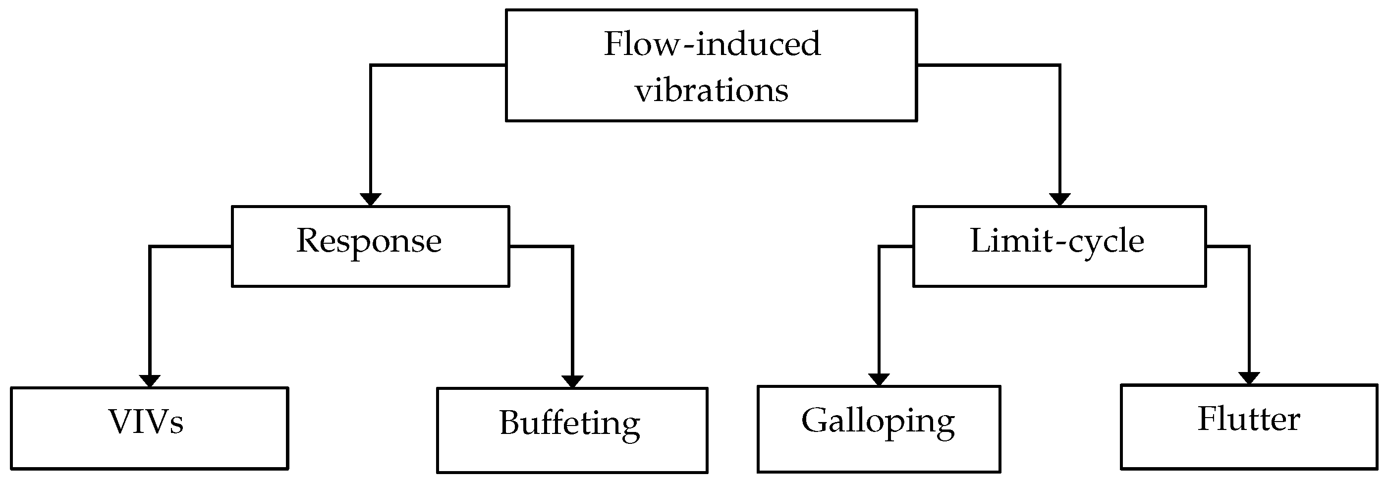
2. Working Principles

The mass-spring-damper system is a fundamental concept in dynamics and control, widely used to model and analyze oscillatory mechanical systems. It consists of three key components: a mass, a spring, and a damper. Although not all real-world systems contain these exact elements, the model effectively represents inertial, elastic, and energy dissipation characteristics, making it a powerful tool for vibrational analysis [18]. The system’s dynamics are governed by a second-order linear differential equation derived from Newton’s second law, given by the following:
m x ¨ + c x ˙ + k x = F ( t )
where m is the mass of the system, c is the damping coefficient, characterising the energy dissipation in the system, k is the spring constant representing the stiffness of the spring, x is the displacement of the mass, and F ( t ) is the external force acting on the mass as a function of time.
The solution to the equation of motion in a mass-spring-damper system provides a comprehensive understanding of the system’s response over time, including the mass’s displacement as it reacts to initial conditions and external forces. It reveals the system’s oscillatory behaviour, indicating whether it exhibits sustained oscillations (in the underdamped case), no oscillations (in the critically damped case), or slow, non-oscillatory motion (in the overdamped case). The solution also identifies the system’s natural frequency and how it responds to external forces, especially if these forces match the natural frequency, potentially leading to resonance. Additionally, it shows the effects of damping on the amplitude and decay rate of oscillations, illustrating how quickly the system returns to equilibrium after a disturbance.

3. Applications of VIV

The potential to harvest energy from VIV has gained considerable attention in recent years, particularly for applications in renewable energy. By capturing the kinetic energy of fluid flows and converting it into usable power, VIVs could provide a novel and sustainable energy source for offshore structures. Several energy conversion mechanisms have been investigated, including electromagnetic, piezoelectric, and triboelectric systems [19,20,21]. Electromagnetic generators, for example, convert mechanical motion into electrical energy through the motion of a conductor within a magnetic field. At the same time, piezoelectric materials generate electrical charge in response to mechanical stress. Triboelectric generators rely on contact electrification, where friction between materials leads to charge generation. Each of these technologies offers unique benefits, though they also face challenges related to efficiency, durability, and scalability. While each mechanism provides unique advantages, their practical efficiency and applicability vary significantly in real-world scenarios. To provide a comprehensive understanding, a comparison of these energy harvesting technologies in terms of their power output and efficiency is presented in Table 1.
In summary, the efficiency and applicability of energy harvesting mechanisms depend significantly on the specific requirements of the application. Electromagnetic systems offer high power output and efficiency but are often bulky and expensive. Piezoelectric systems are compact and efficient but are limited by their frequency range. Although lightweight and affordable, triboelectric systems have lower power output but are highly effective in low-frequency environments. By understanding the strengths and limitations of each mechanism, engineers can select the most appropriate technology for their specific application, thereby maximizing the potential of VIV for renewable energy harnessing.
In this section, we shall explore the applications of VIV energy harnessing in modern engineering practices, focusing on two innovative technologies: the Vortex-Induced Vibration Triboelectric Nanogenerator (VIV-TENG) and Ocean Wave Vortex-Induced Vibration Piezoelectric Energy Harvester (Wave-VIVPEH). VIV-TENG employs VIV caused by fluid flow to generate electrical energy, offering a new method for harvesting energy from low-frequency water flows. The Wave-VIVPEH is a device that harnesses the energy of ocean waves. It collects wave energy using an oscillating water column (OWC) chamber, wind tunnel, and piezoelectric energy converter. The device then converts ultra-low-frequency wave energy into electricity to power devices such as smart buoys.
Furthermore, the practical application of VIV in commercialization, such as the Vortex-Induced Vibration Aquatic Clean Energy (VIVACE) project, should not be overlooked. The VIVACE project uses VIV technology to extract clean energy from ocean waves, demonstrating the potential of VIV in actual energy conversion and environmental cleaning. This technology reduces dependence on traditional energy sources and reduces ecological pollution, providing a new solution for sustainable development.

3.1. Proposed Applications

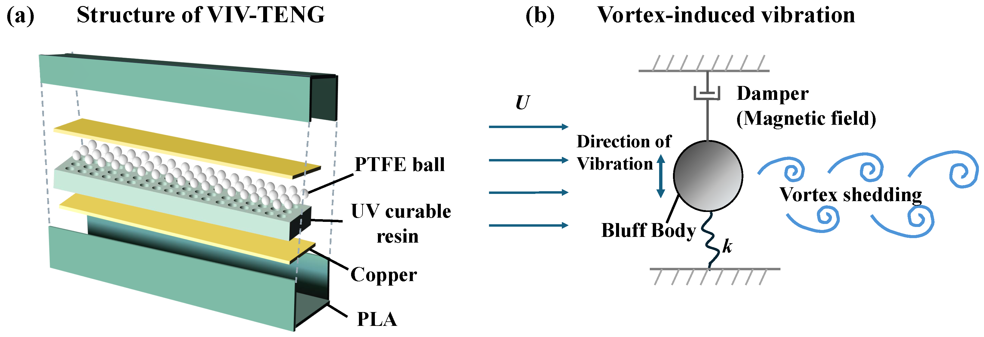
3.1.1. Vortex-Induced Vibration Triboelectric Nanogenerator (VIV-TENG)

Among four types of vibration energy harvesting, electromagnetic energy harvesters are characterized by significant size and high expense, while piezoelectric harvesters operate efficiently only at high vibration frequencies [27,30]. TENG, an innovative approach to harnessing energy, converts mechanical energy into electrical energy through triboelectric charge generation and electrostatic induction. This technology is advantageous due to its affordability, lightweight nature, and, in particular, its effectiveness in capturing energy from low-frequency vibrations [31,32].
As illustrated in Figure 2a, the VIV-TENG structure comprises four primary components: a square cylinder serving as the vibrator, an integrated power generation unit, four suspension springs, and an external support frame. The power generation module incorporates paired copper electrodes, multiple Polytetrafluoroethylene (PTFE) spherical triboelectric elements, and a hexagonal honeycomb structural frame to optimize charge transfer efficiency. As demonstrated in Figure 2b, under fluid flow conditions, periodic vortex shedding develops downstream of the bluff body, generating alternating pressure differentials across the structure. The square cylinder undergoes resonant oscillations when the vortex shedding frequency synchronizes with its fundamental natural frequency. This phenomenon, known as vortex-induced vibration (VIV), occurs within specific flow velocity ranges where the lock-on phenomenon establishes fluid–structure synchronisation. Comparative studies have demonstrated that square cross-section oscillators exhibit 28–42% higher vibration amplitudes and 60% wider lock-on ranges compared to semicircular and circular geometries [33]. The enhanced oscillatory motion translates to greater inertial accelerations within the triboelectric system, proportionally increasing the contact–separation frequency between tribo-layers, thereby improving energy conversion efficiency.
The VIV-TENG has been experimentally validated as an effective mechanism for energy harvesting from low-frequency water flows. Recent studies have demonstrated its potential through laboratory experiments. For instance, a study by Li et al. developed a VIV-TENG that achieved a maximum power output of 1.2 mW at a flow velocity of 0.5 m/s [21]. The device utilised a square cylinder as the bluff body, which exhibited significant vibration amplitudes within the lock-in region, thereby enhancing the triboelectric charge generation. The experimental results showed that VIV-TENG could efficiently convert the kinetic energy of fluid flow into electrical energy, with an energy conversion efficiency of up to 15%. This makes it a promising solution for powering small-scale underwater sensors and devices.

3.1.2. Ocean Wave-Induced Vortex-Induced Vibration Piezoelectric Energy Harvester (Wave-VIVPEH)

The Wave-VIVPEH (Wave-induced Vortex-Induced Vibration Piezoelectric Energy Harvester) is a novel device designed to harness ocean wave energy through airflow-induced vibrations. It integrates an Oscillating Water Column (OWC) chamber, a vent tunnel, and a piezoelectric energy converter. The system converts low-frequency ocean wave motions into high-frequency airflow via the OWC chamber, which then induces vortex shedding around a bluff body in the vent tunnel. This vortex shedding excites the vibration of a piezoelectric cantilever beam, generating electrical energy.
The Wave-VIVPEH has been experimentally validated for its ability to harness energy from ocean waves. The Wave-VIVPEH was developed using an oscillating water column (OWC) chamber and piezoelectric materials. Du et al. tested the device in a wave flume and a wind tunnel [35]. The results showed that it could generate a maximum power output of 3.55 mW under a wind speed of 17.96 m/s in the vent tunnel. The energy harvester demonstrated high efficiency in converting the mechanical energy of wave-induced airflow into electrical energy. This technology has the potential to power smart buoys and other marine monitoring devices, providing a sustainable and reliable energy source.

3.2. Commercialised Applications

3.2.1. Vortex-Induced Vibration Aquatic Clean Energy (VIVACE)

One of VIV’s most notable real-world applications for energy harnessing is the Vortex-Induced Vibration Aquatic Clean Energy (VIVACE) project. This innovative concept was proposed by Professor Michael Bernitsas and his team at the University of Michigan in 2006 [22]. The VIVACE device is designed to convert the kinetic energy of water flow into mechanical energy through the oscillations induced by vortex shedding around a bluff body.
In practical applications, the VIVACE system has demonstrated significant potential for power generation in low-velocity ocean currents. The device consists of oscillators, each equipped with a cylindrical bluff body that vibrates due to VIV. These vibrations are then converted into electrical energy through a mechanical-to-electrical energy conversion system. The VIVACE project has achieved remarkable results in commercial trials, with a maximum energy harvesting power of 600 W to 1000 W per oscillator. The system’s efficiency can reach up to 69%, and it can operate effectively at flow velocities as low as 0.27 m/s [23]. This low-velocity capability makes VIVACE particularly suitable for regions with slow-moving ocean currents, where traditional hydrokinetic energy devices may not be effective.
The VIVACE system also incorporates advanced design features to enhance its performance. For example, Passive Turbulence Control (PTC) devices are added to the surface of the cylindrical oscillators to induce galloping vibrations, which can further increase the energy gain [36]. Additionally, the team developed Virtual Spring Damping Systems to replace traditional physical springs and dampers, improving the work efficiency and measurement accuracy [37,38]. These innovations have significantly contributed to the VIVACE project’s commercial viability, demonstrating VIV’s practical potential for renewable energy generation.

3.2.2. Other Demonstration Projects

Apart from the VIVACE project, several other demonstration projects have successfully utilised VIV for energy harvesting. For instance, a study by Sun et al. [39] reported on a wind energy harvesting system that combines VIV and galloping phenomena. This system uses a novel bluff body design with a D-shaped cross-section, which has shown superior performance in energy conversion efficiency compared to traditional circular cylinders. The results of this study indicate that the combined effect of VIV and galloping can significantly enhance the power output, especially at higher wind speeds.
Another example is the work by Wang et al. [40], who developed a piezoelectric wind energy harvester that leverages both VIV and galloping vibrations. The device uses spindle-like and butterfly-like bluff body shapes to improve energy conversion efficiency. This study’s comprehensive wind tunnel experiments demonstrated that these unique shapes can effectively enhance the power output, making the system more suitable for practical applications.
These examples clearly illustrate that VIV has theoretical potential and practical applications in energy harvesting. The successful implementation of projects like VIVACE highlights the feasibility of utilising VIV as a sustainable and efficient renewable energy source.

4. Design Optimisation

4.1. Bluff Body Design

4.1.1. Shape and Geometry

The shape of the bluff body significantly influences the performance, power generation, and efficiency of vortex-induced vibrations (VIVs) in hydrokinetic energy harvesting applications. Previous research has shown that a circular cross-section is frequently used for bluff bodies, which leads to VIVs occurring within a specific range of low wind speeds, as described by the wake oscillator model [41,42]. This model provides a comprehensive understanding of the interaction between the fluid flow and the structural response, highlighting the importance of the bluff body’s geometry in determining the vibration characteristics.
Many studies have been conducted to compare the performance of blunt bodies with different cross-sectional shapes in terms of displacement and harvested power. The performance of bluff bodies with different cross-sectional shapes also varies regarding displacement and harvested power. Ding et al. [43] systematically investigated vortex-induced vibration (VIV) and energy harvesting of cylinders with different cross-sections, including the PTC-cylinder, square cylinder, Q-trapezoid I, Q-trapezoid II, and triangular prism. The results show that the PTC-cylinder and Q-trapezoid I exhibit stronger VIV responses and energy harvesting performance than the other cylinders. For instance, the maximum amplitude of 3.5D was achieved by the PTC-cylinder and Q-trapezoid I in the fully developed galloping branch. The maximum energy conversion efficiencies of 37.9% and 45.7% were achieved for the PTC-cylinder and Q-trapezoid I, respectively, in the VIV upper branch. In contrast, the Q-trapezoid II displayed a different VIV characteristic with low amplitude and high frequency, and its vortex pattern remained a constant 2S mode. The triangular prism also showed lower energy harvesting efficiency than the PTC-cylinder and Q-trapezoid I. Overall, the cross-sectional shape of the cylinder significantly affected the VIV response and energy harvesting efficiency, with the PTC-cylinder and Q-trapezoid I being the most effective for energy extraction. Zhang et al. analyzed the VIV energy harvesting efficiency of blunt bodies with different cross-sections (triangular prism, square prism, pentagon prism, circular cylinder, and cir-Tria prism) in tandem arrangement [44]. The simulation results indicated that the Cir-Tria prism had better performance on energy harvesting (maximum efficiency: 26.5%), and the square prism had the lowest.
The cross-sectional shape not only affects energy harvesting efficiency but also affects VIV performance. Hasheminejad and Fallahi [45] studied the influence of cylinders of different shapes on fluid mixing performance in a two-dimensional laminar flow channel. Their results indicate that vertical ellipses and tilted square cylinders exhibit the best mixing efficiency in narrow channels, while circular and tilted elliptical cylinders have higher mixing energy costs under certain conditions. Furthermore, different shapes trigger different vortex-shedding modes. Wang et al. found that the downstream vortex shedding mode of a wide D-shaped cylinder is the 2P (two-pair) mode instead of the S (single) mode compared to a fixed cylinder. Its average drag coefficient is higher, indicating that the cylinder’s shape directly affects the vortex shedding structure and flow field characteristics downstream, thus affecting the VIV behaviour [46].

4.1.2. Surface Roughness

As for the study of the surface roughness of the riser, early studies mainly focused on the flow field around a stationary cylinder with different roughnesses in the air environment [47,48,49,50]. Surface roughness significantly alters the boundary layer development and vortex-shedding mechanisms by triggering the early transition from laminar to turbulent flow. As roughness elements (e.g., grooves, dimples) disrupt the laminar boundary layer, they promote flow instability and accelerate the onset of turbulence. This transition modifies the separation points of the boundary layer, shifting them rearward compared to smooth cylinders [47]. Achenbach demonstrated that for a circular cylinder with relative roughness ϵ / D ≥ 0.001, the critical Reynolds number for the “drag crisis” decreases by 30–50%, where ϵ denotes the average roughness height and D the cylinder diameter. This occurs because roughness elements destabilise the laminar flow, reducing the viscous sublayer thickness and enhancing momentum exchange between the near-wall region and the outer flow [51]. Achenbach [47] discovered that as surface roughness increases, the boundary layer separation points on a fixed cylinder shift towards the rear edge, accelerating the transition from laminar to turbulent flow. This transition, in turn, leads to a sudden drop in cylinder resistance under the critical Reynolds number, an event known as “resistance crisis”.
Nakamura and Tomonari [48] measured the mean pressure distribution and Strouhal number ( S t ) across various cylinder surface conditions and found that the critical Reynolds number for resistance crisis decreases with increasing surface roughness. They also observed that when surface roughness exceeds 0.003, the critical and supercritical regions are significantly reduced. The value ϵ / D = 0.003 cited by Nakamura and Tomonari [48] corresponds to the threshold beyond which the drag coefficient ( C d ) stabilizes in the post-critical regime. Here, ϵ / D is quantified using standardised sand-grain roughness measurements, where ϵ represents the equivalent sand-grain height [52]. Beyond this threshold, the boundary layer remains fully turbulent over most of the cylinder surface, suppressing the large-scale separation bubbles characteristic of subcritical flows [53]. Bearman and Harvey [49] further discussed the impact of surface roughness on the S t number, noting that rough cylinders exhibit higher S t numbers than smooth cylinders in the subcritical Reynolds number range, but the trend reverses at the critical Reynolds number. Okajima et al. [50] found that while the VIV amplitude of rough cylinders is smaller than that of smooth cylinders in the subcritical range, it becomes greater in the critical Reynolds number range.
Based on the drag coefficient versus the Reynolds number curve, the four high-Reynolds-number flow ranges relevant to a circular cylinder are referred to as the subcritical, the critical, the supercritical, and the transcritical ranges. However, many studies of free-oscillation tests of smooth circular cylinders have been limited to the subcritical flow regime below the critical Reynolds number. Simulating free-oscillation tests under conditions where the Reynolds number exceeds the critical value at lower test wind speeds is impractical, as the natural frequency of cylinder oscillation is not high, and the critical reduced velocity is fixed. Applying an appropriate level of surface roughness can reduce the drag coefficient, thereby achieving adequate high Reynolds number flow at relatively low Reynolds numbers.

4.1.3. Splitter Plates

Strategies for controlling vortex-induced vibration (VIV) can be categorised into active and passive, with the distinction in the presence or absence of additional energy input. Active control strategies involve modulating power input to address complex flow environments, enabling precise and effortless control of VIV. Passive control strategies primarily involve altering the geometric configuration of the bluff body. Traditional passive VIV control devices are divided into two categories: the first category involves the introduction of additional geometric shapes on or around the cylindrical surface to suppress the VIV and the drag force by streamlining the flow and stabilising the near-wake region. These devices include a splitter plate [54], guided foil [55], fairing [56], and a connected-C device [57]. While they perform well in reducing VIV and drag force, they usually require high costs in installation and maintenance due to their weathervane feature. Hence, such devices may not be attractive to deepwater structures subjected to harsh ocean environments.
In vortex-induced vibrations (VIVs), the study of splitter plates is essential due to their potential to effectively control the vibrational response of cylindrical structures in fluid flow. This vibrational response, particularly in engineering structures such as marine risers, heat exchanger tubes, and suspension bridges, can lead to structural fatigue and even catastrophic failure. Splitter plates influence the vortex-shedding process by altering the wake structure downstream of the cylinder, thereby reducing or suppressing VIV phenomena.
The splitter plate is a structure proposed by Roshko [58] that controls VIV by separating the upper wake region from the lower. Roshko conducted some of the earliest experiments for flow past a cylinder with a rigid splitter plate. It was found that a splitter plate can suppress or weaken, depending on its length, the vortex shedding from a bluff body. Over the past few decades, researchers have also investigated splitter plates, such as flexible splitter plates, double-tail splitter plates with different angles, and parallel and C-shaped splitter plates.
Several studies have explored how varying lengths of an attached splitter plate influence flow characteristics around a stationary circular cylinder [58,59,60,61]. These investigations revealed that attaching a splitter plate to the downstream side of the cylinder can increase base pressure, reduce drag, narrow the wake, and modify the Strouhal number. An optimal plate length exists to achieve minimum drag at a specific Reynolds number. Furthermore, vortex shedding behind the cylinder can be suppressed entirely if the plate length surpasses a certain threshold. Researchers [58,62,63,64] examined the drag and vortex shedding behaviour of a circular cylinder equipped with a detached splitter plate in the wake region. They observed that as the splitter plate is positioned further from the cylinder’s base along the centerline of the wake, the cylinder’s base pressure increases. At the same time, both the drag force and Strouhal number decrease gradually. However, once the distance between the cylinder and the splitter plate exceeds a certain critical point, the base pressure, drag, and Strouhal number revert to values similar to those observed without the splitter plate in place. Cimbala et al. [65,66,67] investigated the flow dynamics around a circular cylinder fitted with a freely rotating splitter plate. Their studies revealed that only splitter plates of adequate length can significantly modify the cylinder’s wake. They also found that a freely rotating splitter plate can achieve a comparable drag reduction to a fixed splitter plate. In conclusion, equipping a stationary circular cylinder with a splitter plate—whether attached, detached, or free to rotate—proves highly effective in controlling vortex shedding and reducing fluid forces on the cylinder.

4.1.4. Grooves

Rather than employing additional passive equipment to alter the geometry and buoyancy characteristics of the riser, surface modification techniques can serve as an alternative approach to simultaneously decrease both vibration amplitudes and hydrodynamic forces. The second category of passive VIV-control strategies concentrates on modifying the circular cross-section of the cylinder.
Huang [68] conducted experiments to investigate the impact of three-start helical grooves on the drag reduction of a fixed circular cylinder and VIV responses of an elastically supported cylinder. The study revealed that the helical grooves could significantly reduce the crossflow VIV amplitude and the inline drag coefficient. However, the grooves were not negligible in size, implying that cylinders with grooves required larger diameters to ensure adequate wall thickness of the riser. Law and Jaiman [57] conducted a numerical analysis on the VIV mitigation effects of a surface-modification device, specifically spanwise grooves, on the deflection and hydro-force responses of a circular cylinder. They examined two groove configurations: the staggered groove and the helical groove. Their findings indicated that the spanwise staggered grooves presented the best VIV suppression effectiveness concerning crossflow vibration amplitude and drag force by up to 37% and 25%. Zhou et al. [69] experimented to study a cylinder’s drag coefficient and flow characteristics with longitudinal grooves. They observed that the wake behind a grooved cylinder was more compact in the inline direction and narrower in the crossflow direction than that of a smooth cylinder under similar flow conditions. Additionally, the mean drag coefficient reduction could reach 18–28%. Conversely, an improper arrangement of grooves could significantly enhance the VIV response of the cylinder [70,71,72].

4.1.5. Mass

Optimising VIV energy harvesters requires balancing maximising energy output and ensuring structural stability. This balance is critical because high energy output typically demands large vibration amplitudes, while excessive amplitudes can lead to structural fatigue and failure. Adjusting the mass ratio is an effective method for balancing energy output and structural stability. The mass ratio m * , defined as the ratio of the oscillating structure’s mass m to the displaced fluid mass m d , is a pivotal parameter in studying cylinders’ VIV.
Researchers have recognised the role of mass ratio in determining the amplitude and frequency of VIV. Mittal and Kumar [73] conducted extensive research on the effect of mass ratio on the VIV of circular cylinders, discovering that a low mass ratio leads to a “soft lock-in” phenomenon, where the non-dimensional vibration frequency is lower than the natural frequency of the cylinder. This condition can enhance energy output but may also increase the risk of structural failure due to large amplitudes. Conversely, a higher mass ratio stabilises the system but reduces energy output. Sen and Mittal [74] found that a mass ratio greater than five introduced additional galloping branches, which enhanced energy harvesting efficiency without compromising structural integrity. Engineers can optimise the system for energy output and stability by carefully selecting the mass ratio.
Williamson and Govardhan [75] revealed the effects of mass ratio on the VIV response of cylinders through extensive experimental and theoretical analyses. They discovered that at low mass ratios, the VIV response of cylinders exhibits three distinct branches: the initial branch, the upper branch, and the lower branch, each corresponding to different vortex shedding modes. Notably, when the mass ratio falls below a critical value, the cylinder enters an infinitely vast resonance region, known as the “resonance forever” phenomenon. This indicates that at extremely low mass ratios, the cylinder will continue to vibrate with large amplitudes even at infinitely high flow velocities.
Furthermore, Jauvtis and Williamson [76] experimentally studied the VIV of a cylinder under low mass and damping conditions with two degrees of freedom (X, Y motion). They found that even at low mass ratios, the cylinder’s transverse vibration response and vortex shedding modes are similar to those when only transverse motion is allowed. However, a new, extremely high-amplitude “super-upper branch” emerges below a certain mass ratio threshold, associated with a triple vortex shedding mode (2T mode).
In summary, the mass ratio significantly influences the VIV characteristics of cylinders, with lower mass ratios leading to different vibrational behaviours compared to higher mass ratios. This understanding is crucial for predicting and controlling VIVs, enhancing the reliability and safety of structures subjected to fluid-induced vibrations.

4.2. Bluff Body Arrangements

Vortex-induced vibration (VIV) is critical in offshore and bridge engineering. The in-depth study of the flow structure is essential for understanding the dynamic response of structures and designing effective vibration mitigation measures. The VIV phenomenon is particularly complex in multi-column structures, involving the interaction and energy transfer of flows between columns, which not only affects the stability and safety of structures but also relates to the effective utilisation of energy [77]. Therefore, investigating the flow structure between multi-columns is of great theoretical and practical significance for optimising structural design, improving energy capture efficiency, and reducing maintenance costs.
Numerous studies on the flow between two cylinders have demonstrated that the flow characteristics around a single cylinder can be significantly altered when additional cylinders are introduced nearby. The flow field within a multi-columnar structure is characterised by intricate interactions among shear layers, vortices, wake trails, and Kármán vortex streets, which collectively contribute to the complex dynamics of the system. Zdravkovich [78] categorised fluid disturbances in two-cylinder flows into trailing and neighbouring disturbances based on the position of the downstream cylinder. Trailing disturbances occur when one cylinder is within the wake of another, altering the flow characteristics of the downstream cylinder. This is commonly seen in tandem cylinder arrangements, especially at low Reynolds numbers where the unsteady flow exhibits a dominant frequency. Neighbourhood disturbances arise when cylinders are nearby without one being in the other’s wake, affecting vortex detachment behaviour, which is challenging to predict due to the lack of visible wake displacement. Gu and Sun [79] further refined this classification into three types, wake, shear layer, and neighbourhood disturbances, providing a more comprehensive understanding of multi-cylinder interactions. Alternative classifications for two-cylinder arrangements consider changes in the flow field, mean lift and drag [80], pitch ratio, angle of incidence, and Reynolds number derived from experimental data and measurements. Flow visualisation techniques, such as those used by Lgrashi [81,82], have identified multiple flow patterns in various combinations of L / D and R e , helping to understand different geometries. Numerical simulations have also been employed to study the flow around two cylinders, providing further insights into the complex fluid dynamics [83,84,85].
The most basic arrangement of multiple slender structures consists of two cylinders positioned in tandem, side-by-side, or staggered configurations. The most studied cylinder arrangements are tandem (Figure 3a) and side-by-side (Figure 3b), where the geometry is described by the streamwise distance (L) and the cross-stream distance (T) between the cylinders of diameter D. Some authors refer to the gap width (G) for side-by-side configurations. The staggered configuration of two cylinders, commonly encountered in practice due to the rarity of perfectly aligned flows, is defined by the centre-to-centre pitch (P) and the angle of incidence ( α ), as depicted in Figure 3c. Interactions between the airflow around the two cylinders can lead to flow detachment, reattachment, vortex impacts, circulation zones, and quasi-periodic vortex formations. These features encompass the majority of flow characteristics typically observed in multi-structure setups. Consequently, studying the flow dynamics around two cylinders is a practical framework for understanding the principles of fluid motion and passive scalar transport around more complex structures. The complex interactions between two cylinders in different arrangements have been extensively studied through various experimental, numerical, and theoretical approaches. This section reviews the main findings and advances in the field, focusing on the effects of spacing, Reynolds number, and vortex shedding dynamics.

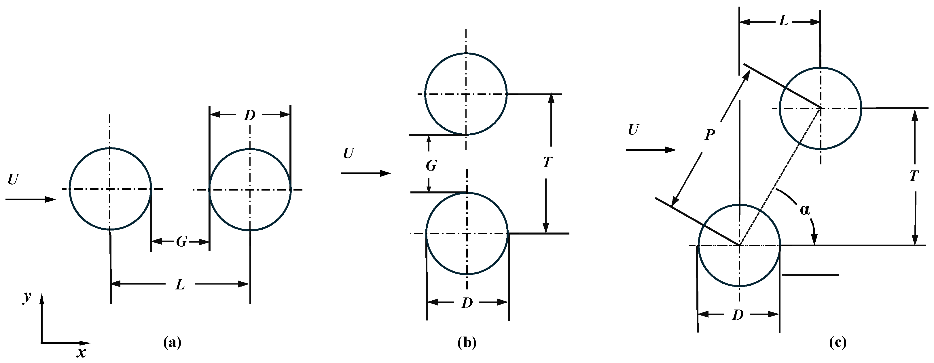
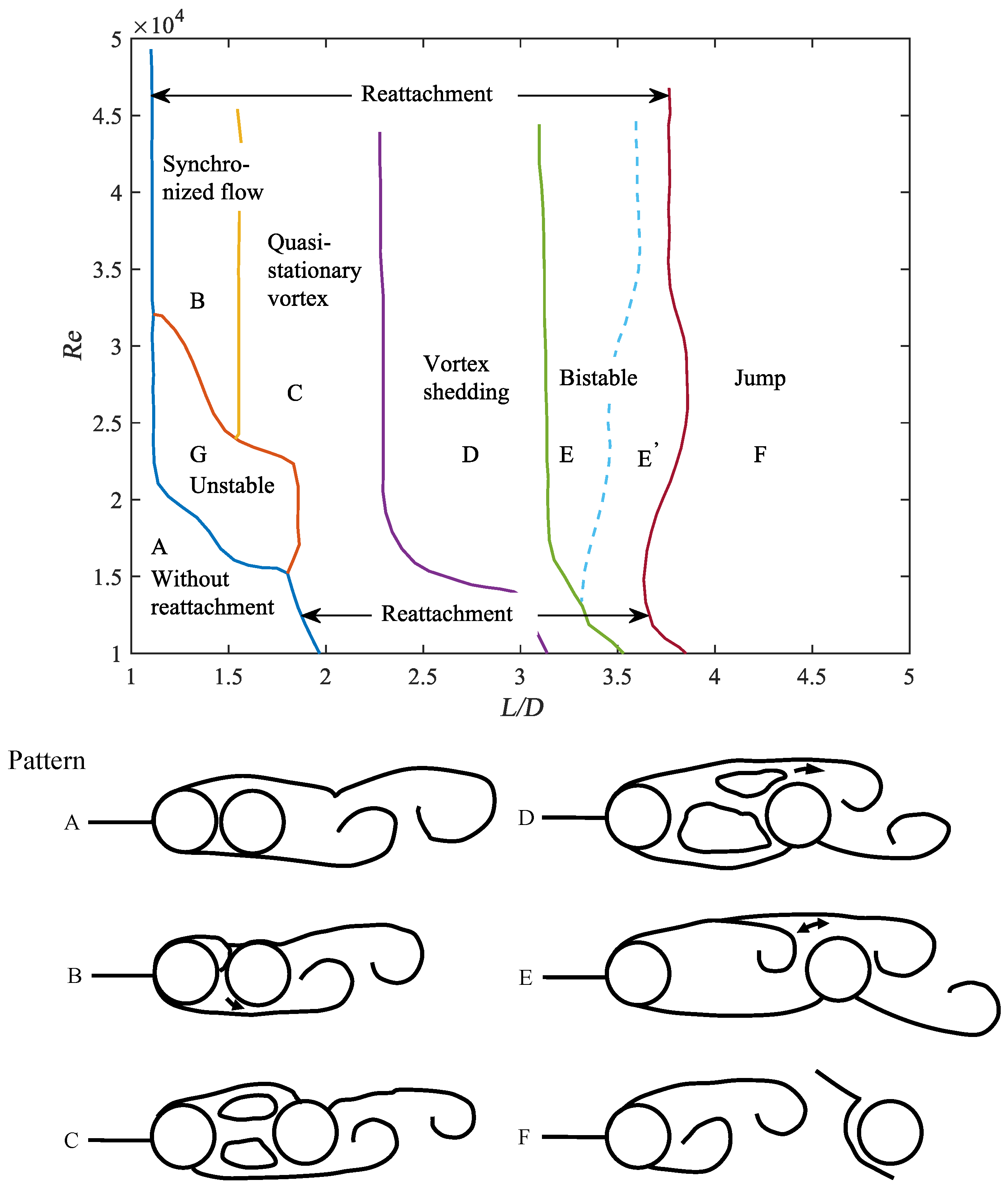
4.2.1. Tandem Configuration

The tandem arrangement of cylinders serves as a canonical model for studying multiple cylindrical structures, as it elucidates the fundamental phenomena and mechanisms inherent in such systems [87]. In a tandem arrangement where two circular cylinders are aligned in line and parallel to the main flow (as depicted in Figure 3a), the upstream cylinder provides partial shielding for the downstream cylinder, thereby modifying the flow conditions it experiences. The wake of the upstream cylinder impacts the incident vorticity field that affects the downstream cylinder [88]. Concurrently, the downstream cylinder influences the wake dynamics and the region of vortex formation of the upstream cylinder. This mutual interference allows the upstream cylinder to act as a turbulence generator, while the downstream cylinder can serve as a drag-reducing device or “wake stabiliser” [89]. The interaction between the two cylinders can cause them to behave either as a single bluff body or as distinct entities, depending on the centre-to-centre spacing.
The study of complex flow dynamics around two tandem cylinders focuses more on the effects of key parameters such as inter-column spacing, Reynolds number, and Stewart’s coefficient (the ratio of elastic forces to inertial forces within the system). The flow around two tandem circular cylinders is sensitive to both the Reynolds number ( R e ) and the spacing ratio of the cylinders to their diameters ( L / D ). Based on this property, Igarashi [81,82] has pioneered tandem configurations by classifying eight different types of flow patterns for two equal-diameter tandem circular columns in a steady cross flow, as shown in Figure 4. According to Zdravkovich’s approach, the flow patterns in Figure 4 can be subdivided into three basic types of wake interference behaviour: single bluff body behaviour, shear layer reattachment behaviour, and Kármán vortex shedding from each cylinder, also referred to as the “extended-body” regime, “reattachment” regime, and “co-shedding” regime [69,90].
In the context of small pitch ratios (approximately 1 < L / D < 2 ), the two cylinders exhibit behaviour akin to a single bluff body or an “extended body” [81]. The separated shear layers from the upstream cylinder are compelled to enclose or wrap around the downstream cylinder without reattaching to its surface before rolling up alternately into Kármán vortices behind the downstream cylinder. In certain aspects, the downstream cylinder can be considered to behave similarly to a short splitter plate [69]. The gap between the cylinders is presumed to be primarily filled with stagnant fluid [92]. Compared to the single-cylinder case, the wake is narrower. The vortex roll-up behind the downstream cylinder is closer to the cylinder [93,94] as the pitch ratio increases to the intermediate range (approximately 1.2–1.8 < L / D < 3.4–3.8 [78] or 2 < L / D < 5 [69], depending on the range of R e ), the cylinders are positioned far enough apart that the shear layers from the upstream cylinder no longer enclose the downstream cylinder. Instead, these layers are reattached to the downstream cylinder. Numerous studies have aimed further to delineate the flow regime within this pitch ratio range. For instance, within the range 1.1 < L / D < 1.6 , the shear layers from the upstream cylinder may alternately reattach onto the front face of the downstream cylinder, this reattachment process being synchronised with Kármán vortex shedding from the downstream cylinder. And within 1.6 < L / D < 2.3–2.4, shear layer reattachment may be nearly continuous and a pair of quasi-stationary eddies forms in the gap. At higher pitch ratios ( 2.5 < L / D < 3.1–3.5 [81]) within the reattachment regime, the shear layers enclosing the gap may exhibit more oscillatory behaviour [91] and intermittent shedding of the gap vortices [81] may occur, interfering with vortex shedding from the downstream cylinder [78,92]. As L / D continues to increase to approx. L / D = 3.4–3.8 [78] or L / D > 5 [69], the downstream cylinder is far enough away that Kármán vortex shedding can now occur in both the upstream and downstream cylinders [69,78]. At this point, the downstream cylinder is located outside the vortex-forming region of the upstream cylinder [95] and is subjected to periodic impacts from Kármán vortices shed by the upstream cylinder. In this "co-shedding" flow state, vortex shedding occurs at the same frequency in both cylinders, and vortex shedding in the downstream cylinder is triggered by the arrival of vortices generated in the upstream cylinder [96]. Table 2 is a supplementary summary of studies on VIV of tandem circular cylinders with different spacing ratios L / D as follows.

4.2.2. Side-by-Side Configuration

When two circular cylinders are arranged in a side-by-side configuration transverse to the mean flow, their wake interactions exhibit complex patterns governed by the transverse pitch ratio ( T / D ). Three distinct flow regimes emerge as the spacing increases: single bluff body behavior (1 < T / D < 1.2), biased flow patterns (1.2 < T / D < 2.2), and parallel vortex streets ( T / D > 2.5). These regimes are characterised by fundamentally different vortex formation mechanisms and wake interactions, as illustrated in Figure 3b.
At minimal spacing ( T / D < 1.2), the system behaves as a composite bluff body with combined shear layers. This phenomenon arises from strong viscous interactions between the cylinders, suppressing gap flow development [107]. The inner shear layers remain attached due to proximity effects, while vortex shedding occurs exclusively from the outer shear layers, forming a unified wake structure reminiscent of base-bleed configurations [108,109]. Instantaneous flow fields reveal both symmetric and asymmetric near-wake patterns: symmetrical configurations maintain aligned gap flows, whereas asymmetrical patterns exhibit intermittent deflection toward one cylinder [110,111]. At T / D = 1.1, this deflection creates separation bubbles on the affected cylinder’s surface—a feature absent at T / D = 1.2 [112]. The transitional regime ( T / D = 1.1–1.2) demonstrates four distinct near-wake modes involving dynamic switching of gap flow direction and bubble formation/rupture [112].
Intermediate spacing (1.2 < T / D < 2.2) introduces biased flow patterns characterised by asymmetric wake interactions. The phenomenon of biased flow patterns in side-by-side cylinder configurations at intermediate pitch ratios ( T / D ) has been validated by multiple experimental and numerical studies. Sumner et al. experimentally demonstrated that for transverse spacing ratios 1.1 < T / D < 2.2, the gap flow deflects asymmetrically toward one cylinder, resulting in an asymmetric near-wake structure and distinct vortex shedding frequencies [110]. Alam et al. utilised particle image velocimetry (PIV) to reveal bistable switching of gap flow direction within T / D = 1.1–1.6, accompanied by intermittent separation bubble formation [113]. Zdravkovich attributed this biased flow to shear layer interactions and asymmetric vortex pairing in the gap region [92]. Furthermore, Xu et al. confirmed the persistence of biased flow patterns at low Reynolds numbers ( R e = 150–300), emphasising their stability in intermediate T / D regimes [114]. These findings collectively corroborate the existence of biased flow patterns in side-by-side cylinder arrangements at intermediate pitch ratios. The gap flow develops periodic deflections toward either cylinder, creating unequal pressure distributions that sustain the asymmetry. PIV measurements by Zhou et al. [115] revealed this bias originates from competing instability modes in the inner shear layers. This regime exhibits intermittent synchronisation between the cylinders’ vortex shedding frequencies, though complete lock-in rarely occurs [86].
At larger spacings ( T / D > 2.5), the cylinders shed independent Kármán vortex streets with weak interaction. Both inner and outer shear layers develop freely, producing parallel vortex streets that occasionally demonstrate in-phase or anti-phase synchronisation [116]. Notably, the critical spacing for complete flow independence decreases with increasing Reynolds number ( R e > 1 × 10 4 ), as turbulent mixing accelerates wake decay [117].
In the parallel configuration of cylinders, the concurrent occurrence of two side-by-side vortex detachment processes and vortex streets gives rise to intricate interactions within the combined wake of the cylinders. As the ratio of the spacing to diameter ( T / D ) increases, the vortex streets exhibit a predominant anti-phase synchronisation. This synchronisation manifests as a simultaneous detachment of vortices across the cylinder gap, culminating in a stable vortex pattern within the composite wake of the dual cylinders. In some cases, the flow pattern may intermittently switch to the same phase of the vortex street and then revert to the anti-phase synchronisation. Synchronisation results in an unstable configuration of vortices and leads to the formation of a single wake behind the cylinder pair containing a binary vortex street. The following Table 3 is a supplementary summary of studies on VIV of side-by-side circular cylinders with different spacing ratios T / D .

4.2.3. Staggered Configuration

The staggered cylinder configuration (Figure 3c) represents the most complex flow interaction scenario, exhibiting diverse wake patterns that depend on both longitudinal ( P / D ) and transverse ( T / D ) spacing ratios. Building upon Zdravkovich’s foundational classification [80], Gu and Sun’s experimental study at high subcritical Reynolds numbers ( R e = 2.2 × 10 5 3.3 × 10 5 ) identified three primary interference mechanisms: wake interaction, shear layer interaction, and proximity effects [79]. Subsequent PIV investigations by Sumner et al. in the low subcritical regime ( R e = 850–1900) revealed nine distinct flow patterns through comprehensive flow visualisation, demonstrating significant Reynolds number dependence in vortex formation mechanisms [85].
At close longitudinal spacing ( 1 P / D 1.25 ), the cylinder pair behaves as a composite bluff body with synchronised vortex shedding from merged shear layers. This coalescence phenomenon creates enhanced vibration coupling compared to isolated cylinders, particularly in the lock-in regime [75]. Three characteristic patterns emerge: (1) complete shear layer merging with a unified vortex street, (2) partial attachment with intermittent gap flow deflection, and (3) asymmetric wake modulation with secondary vortex pairing. For moderate spacing ( 1.125 P / D 4 ) at small incidence angles ( α 30 ° ), the flow exhibits three distinct interaction modes. The shear layer reattachment regime ( P / D = 1.125–4, α = 0–20°) features upstream cylinder shear layers attaching to the downstream surface, suppressing vortex formation on the adjacent face. This flow modification significantly alters the pressure distribution, creating unique lift force bimodality [128]. The induced separation regime ( P / D = 1.125–3, α = 10–30°) demonstrates gap flow deflection generating secondary vorticity on the downstream cylinder’s inner surface, while the vortex impingement regime ( P / D = 3–5, α = 0–20°) shows upstream vortices periodically impacting the downstream cylinder, inducing enhanced vibration amplitudes. Such interactions can amplify VIV responses by 40–60% compared to isolated cylinders when synchronisation occurs [129]. The following Table 4 is a supplementary summary of studies on VIV of staggered circular cylinders with different spacing ratios and incidence angles.
Depending on their spatial configurations, the wake interactions between multiple cylinders are governed by distinct flow patterns and vortex-shedding modes. In tandem arrangements, at a small pitch ratio ( L / D < 3), the upstream cylinder suppresses vortex shedding from the downstream cylinder, creating a shielded wake region dominated by shear layer reattachment and gap flow stagnation [91]. As L / D increases beyond 3.5, a co-shedding regime emerges, characterised by synchronised Kármán vortices from both cylinders. Notably, the downstream cylinder exhibits enhanced vortex shedding frequency modulation, with phase differences between the cylinders leading to alternating constructive and destructive interference in lift forces [90]. The middle cylinder experiences dual resonance peaks for three tandem cylinders due to combined upstream wake turbulence and downstream feedback effects, resulting in a 25% amplitude amplification compared to isolated cylinders [137].
In side-by-side configurations ( T / D = 1.2–2.5), bistable biased flow dominates, where gap flow periodically deflects toward one cylinder, generating asymmetric vortex streets. High-resolution PIV studies reveal dual spectral peaks in lift fluctuations: one at the Strouhal frequency ( S t ≈ 0.2) and another at a lower frequency ( S t ≈ 0.05) corresponding to gap flow switching [132]. At T / D > 2.5, anti-phase vortex shedding dominates, forming a merged wake with alternating vortex pairing, while in-phase shedding induces unstable binary vortex streets [110].
The wake interactions in staggered cylinder configurations exhibit highly nonlinear dynamics governed by the combined effects of longitudinal spacing ( P / D ), transverse spacing ( T / D ), and incidence angle ( α ). For two cylinders with P / D = 2.5 and α = 30°, the upstream cylinder’s shear layers partially reattach to the downstream cylinder’s surface, generating secondary vorticity that amplifies transverse vibration amplitudes by 35–40% compared to isolated cylinders [96]. At α = 45 ° , alternating vortex impingement occurs, where vortices shed from the upstream cylinder periodically strike the downstream cylinder, inducing dual-frequency lift fluctuations [85].

4.3. Virtual Spring Damper Systems

Vortex-induced vibrations (VIV) can lead to intense oscillations, which may ultimately cause structural failure. However, VIV can also be harnessed for energy harvesting, where the focus shifts to maximising the amplitude of vortex-induced vibrations. This amplitude directly impacts energy conversion efficiency and the resulting power output; higher amplitudes generally indicate a more significant potential for energy capture. Nonetheless, larger amplitudes can also accelerate structural fatigue and damage. Therefore, a key research objective in this field is to optimise the vibration amplitude to enhance energy conversion efficiency while maintaining structural integrity.
One major difficulty in analysing the oscillation amplitudes was the significant scattering of the available experimental data obtained for various mass ratios m * and Reynolds numbers R e D . Different experimental setups have been considered in the literature to overcome this difficulty. Feng [138] used an electromagnetic-eddy-current damper to study the effect of damping on VIVs of circular and D-shaped cylinders. However, the investigation was predominantly constrained by a high mass damping ratio ( m * ζ 0.35 ), leading to vibration responses that were solely of the low-amplitude bimodal variety and failing to investigate the VIV behaviour at elevated amplitudes thoroughly. Khalak and Williamson identified the limitations of peak amplitude predictions in VIV under low mass damping by introducing a modified parameter ( m * + C a ) ζ accounting for added mass effects [117]. The term C a represents the added mass coefficient, which quantifies the inertial contribution of the surrounding fluid during oscillatory motion, while ζ = c / ( 2 k m ) is the damping ratio, where c, k, and m denote the system’s damping coefficient, stiffness, and mass, respectively. The modified parameter combines these factors to characterise the effective damping in fluid–structure interaction systems [139]. More recently, Klamo et al. [140] proposed a variable magnetic eddy-current damping system. Govardhan and Williamson [141] revisited earlier hypotheses and developed a variable damping system using a spring mechanism, in which the base moves in or out of sync with the velocity of the oscillating mass. This setup generates a force that is directly proportional to the velocity of the oscillating mass, allowing them to adjust ζ by applying either positive or negative damping.
Hover et al. [142] were the first to implement the concept of cyber-physical devices (proposed by Miller). They implemented forces acting on an oscillating cylinder via a force feedback controller. They used it to drive a real-time simulation of the one-dimensional motion equation, making the cylinder move along a predicted trajectory. However, because noisy force signals require filtering, force-feedback controllers have the drawback of causing a phase lag between the cylinder’s displacement and the actual force acting on the oscillating body. Bernitsas et al. [22] pointed out that this phase lag is a factor that negatively impacts energy harvesting. To overcome this shortcoming, Lee et al. [37] developed a virtual damper–spring system that uses a servo motor to generate feedback force based on displacement and velocity data. This system eliminates phase lag and allows precise damping control, enhancing energy harvesting efficiency while maintaining structural stability. Additionally, nonlinear damping systems have shown promise in broadening the frequency response and reducing the likelihood of resonance. For example, a study by Khalak and Williamson [117] introduced a modified parameter accounting for added mass effects, which improved the prediction of peak amplitudes and optimised damping for energy harvesting applications.

4.4. Nonlinear System Improvements

4.4.1. Nonlinear Damping Systems

Nonlinear damping systems play a pivotal role in vibration control, particularly in fluid–structure interactions where linear damping models often fall short of accurately capturing the complex dynamics. Incorporating nonlinear damping mechanisms has led to significant advancements in the design and performance of vibration control strategies, providing broader bandwidth and enhanced energy dissipation capabilities. Nonlinear damping systems are characterised by their ability to exhibit varying levels of damping forces with changes in velocity, which is a departure from the constant damping ratio observed in linear systems. The nonlinear damping force can be represented as a function of velocity, displacement, or both and is often modelled using polynomial expressions or other empirical relationships.
In vortex-induced vibrations (VIVs), nonlinear damping systems mitigate the high amplitude oscillations that can lead to resonance and structural fatigue. By introducing nonlinearity, these systems can broaden the frequency response and reduce the likelihood of lock-in, thereby enhancing the overall stability and reliability of the structure. Recent research has focused on developing novel nonlinear damping systems that can adapt to varying operational conditions and enhance vibration suppression capabilities. This includes using smart materials, such as magnetorheological (MR) dampers, which can actively adjust their damping properties in response to changes in the external magnetic field. Additionally, nonlinear energy sink (NES) integration has shown promise in providing broadband vibration suppression by capturing and dissipating energy from the primary system through nonlinear interactions.
In VIV applications, the use of nonlinear damping systems has been validated through both experimental and numerical studies. Mackowski and Williamson [143,144] conducted experimental studies using Cyber-Physical Fluid Dynamics (CPFD), a sophisticated closed-loop control system that generates nonlinear restoring forces via force feedback. The system applies a nonlinear Duffing relationship to calculate the restoring force based on cylinder displacement. The study revealed that increasing the nonlinear coefficient shifts the amplitude versus Reynolds number envelope towards higher Reynolds numbers, effectively reducing the risk of resonance and structural fatigue. And Wang et al. [145] performed two-dimensional numerical simulations on the VIV of a single circular cylinder with one degree of freedom (1-DOF) under nonlinear restoring forces described by the Duffing equation. The study found distinct vibration response branches and demonstrated how the presence and characteristics of these branches vary with the spring’s nonlinearity. This research confirmed that nonlinear damping systems can significantly reduce vibration amplitudes, thereby enhancing structural stability. The findings from these studies highlight the potential of nonlinear damping systems to enhance the stability and efficiency of VIV-based energy harvesting and structural applications.

4.4.2. Bio-Inspired Adaptive Damping

Bio-inspired adaptive damping systems represent a cutting-edge approach to vortex-induced vibrations (VIVs), drawing inspiration from nature’s solutions to dynamic stability and energy management. These systems aim to emulate the adaptability observed in biological systems, which can adjust their damping characteristics in response to varying environmental conditions, thereby enhancing performance and survivability. Bio-inspired adaptive damping systems integrate principles observed in natural systems, such as the variable damping mechanisms found in animal locomotion or the energy dissipation strategies employed by plants in response to wind-induced vibrations. The core concept is to develop damping systems that can dynamically adjust their properties based on real-time feedback, like biological systems responding to environmental changes.
Bio-inspired adaptive damping systems have shown substantial improvements in efficiency compared to conventional damping systems. In a numerical study by Mackowski and Williamson [143,144], the effectiveness of bio-inspired adaptive damping systems was further validated using Cyber-Physical Fluid Dynamics (CPFD). The study found that the adaptive damping system could achieve a 20.5% reduction in vibration amplitude compared to traditional damping systems while maintaining structural stability. This reduction in amplitude directly translates to a significant decrease in the risk of structural fatigue and failure. Another notable example is the application of bio-inspired adaptive damping in wave energy converters (WECs). A study by Ye et al. [146] demonstrated that the use of adaptive damping systems in WECs resulted in a 10.61% improvement in wave energy harvesting efficiency compared to conventional systems. This was achieved through the integration of deep reinforcement learning (DRL) algorithms, which allowed the system to adapt to varying wave conditions in real time. These improvements highlight the ability of adaptive damping systems to dynamically adjust to varying conditions, thereby enhancing energy capture and structural stability.
By incorporating nonlinear, velocity-proportional damping coefficients, these systems can more effectively manage the energy transfer between the fluid and the structure, particularly during transitions from VIV to galloping motions [147]. This adaptability prevents the system from shutting down due to excessive damping or operating inefficiently due to insufficient damping, thus optimising the energy harnessed from fluid flows. The effectiveness of bio-inspired adaptive damping systems has been evaluated through experiments, with parameters such as damping-to-velocity rate, linear spring stiffness, and flow velocity manipulated. These experiments, conducted over a range of Reynolds numbers (30,000 ≤ Re ≤ 120,000), have demonstrated that adaptive damping systems can increase the harnessed power by 51–95% compared to linear oscillators [148]. Furthermore, they have shown an expansion in the operational range of flow velocities and improved stability at lower flow speeds, where traditional damping systems often result in unstable oscillations.

4.4.3. Variable Stiffness

Variable stiffness systems leverage the principle of altering the stiffness of a structure to control its dynamic response to fluid-induced forces. By adjusting the stiffness, these systems can optimise the energy transfer between the fluid and the structure, thereby reducing the amplitude of vibrations and preventing resonance. The variable stiffness mechanism can be actuated through various means, including shape memory alloys, electroactive polymers, or magnetorheological fluids, allowing real-time adjustments based on flow conditions.
In the context of VIV, variable stiffness systems can significantly enhance the performance of structures such as offshore platforms and other bluff bodies subjected to fluid flow. By dynamically adjusting the stiffness, these systems can shift the structure’s natural frequency away from the vortex shedding frequency, thus avoiding the lock-in phenomenon and reducing the risk of fatigue damage [149]. The adaptive nature of variable stiffness systems provides a distinct advantage over traditional passive damping methods, which are limited by fixed parameters.
At present, variable stiffness systems have been applied in the field of VIVs. Hosotani et al. investigate the vortex-induced vibrations (VIVs) of a long slender cylinder under steady and pulsating flow using a VIV hydroelectric generator equipped with a variable stiffness controller that can adjust the length of the plate spring according to the frequency of vortex shedding [150]. By designing and applying a variable stiffness system, precise control and optimisation of VIVs can be achieved, thereby improving the stability and performance of the structure. Future research directions include further optimising the design of variable stiffness systems, developing new intelligent materials and variable stiffness structures, and strengthening interdisciplinary research to promote the wider application of variable stiffness systems in the field of VIVs.

5. Conclusions

This review critically synthesizes the transformative potential of vortex-induced vibration (VIV) oscillators in hydrokinetic energy harvesting, delineating quantitative design principles and performance benchmarks that distinguish this technology from conventional approaches. The interplay between energy conversion mechanisms, oscillator design, and adaptive control strategies forms the cornerstone of VIV-based energy systems, revealing a series of universal principles that transcend specific experimental configurations.
The performance of VIV energy harvesters is profoundly influenced by the choice of energy conversion technology. Electromagnetic systems, characterized by high power density, dominate in high-velocity flow regimes (>1.5 m/s) but face limitations in scalability under turbulent conditions. Piezoelectric mechanisms offer compact integration for moderate-frequency oscillations, yet their efficiency diminishes in ultra-low-frequency environments. In contrast, triboelectric nanogenerators, exemplified by VIV-TENG, uniquely capitalize on low-amplitude vibrations inherent to marine settings, demonstrating exceptional adaptability to sluggish flows (<0.5 m/s). This divergence underscores a fundamental trade-off: energy conversion mechanisms must align with target flow characteristics, where power output, frequency range, and environmental robustness are mutually constraining variables.
Oscillator geometry emerges as a decisive factor in modulating vortex dynamics and lock-in behaviour. Non-circular bluff bodies, such as square or D-shaped profiles, enhance energy capture by extending synchronization ranges between vortex-shedding frequencies and structural resonance. For instance, square oscillators amplify transverse vibration amplitudes by 28–42% and extend lock-in ranges by 60% through enhanced vortex–structure synchronization. Surface modifications, including splitter plates and helical grooves, refine wake interactions to suppress detrimental vibrations while preserving vortex coherence, thereby optimizing the balance between drag reduction and energy extraction. Surface roughness introduces a nuanced duality: moderate roughness stabilizes oscillations by disrupting boundary layer separation, yet excessive texturing attenuates vortex shedding intensity, necessitating scenario-specific optimization to harmonize structural durability with energy yield.
Dynamic control strategies further bridge the gap between theoretical potential and practical viability. Adaptive damping systems, such as bio-inspired mechanisms and variable stiffness frameworks, dynamically adjust to fluctuating hydrodynamic conditions, decoupling energy harvesting from rigid frequency matching. Nonlinear damping mechanisms mitigate resonance risks while expanding operational bandwidths. For example, nonlinear damping systems outperform linear counterparts by expanding operational bandwidths by 40–60%. Machine learning-driven predictive control optimizes real-time responses to transient flow patterns, achieving 95% energy retention during flow shifts. These advancements collectively enable oscillators to maintain high efficiency across diverse and unpredictable marine environments.
The VIVACE project exemplifies the practical application of these principles, scaling single-oscillator outputs to 600–1000 W through virtual spring-damping algorithms that maintain 69% efficiency at 0.27 m/s—a benchmark unachievable with traditional offshore turbines. This project highlights the potential of VIV technology to reduce the reliance on traditional energy sources and decrease environmental pollution.
Future investigations should prioritize the design of hybrid energy harvesters that synergistically couple VIVs with complementary flow-induced vibration phenomena—notably, galloping and flutter—to establish broadband energy capture capabilities across turbulent flow regimes. Additionally, exploring multi-objective optimization frameworks, guided by computational fluid dynamics (CFD), will be crucial for reconciling conflicting parameters and optimizing the design of VIV systems. Field validations under realistic flow conditions and ecological impact assessments will be essential for transitioning laboratory innovations into deployable solutions. By addressing these areas, the field of VIV-based energy harvesting can continue to advance, contributing to the growing need for efficient and sustainable energy solutions.

Author Contributions

Conceptualization, D.C., J.H., O.V.Y., M.R.S., R.G., A.B., S.D.C., Z.L., C.S.C. and H.C.; methodology, D.C., J.H. and H.C.; formal analysis, D.C., J.H. and H.C.; investigation, D.C., J.H. and H.C.; writing—original draft preparation, D.C., J.H., S.Z.C., M.R.W. and I.Z.L.K.; writing—review and editing, D.C., J.H., H.Z., Y.Z., S.Z.C., M.R.W., I.Z.L.K., O.V.Y., M.R.S., R.G., A.B., S.D.C., Z.L. and C.S.C.; supervision, H.C. and D.C.; project administration, H.C., D.C., M.R.S., R.G., A.B., S.D.C., Z.L. and C.S.C.; funding acquisition, H.C., D.C., M.R.S., R.G., A.B., S.D.C., Z.L. and C.S.C. All authors have read and agreed to the submitted version of the manuscript.

Funding

The financial support from the Royal Academy of Engineering—TSP-2325-5-IN\196 is acknowledged. The authors would like to acknowledge the support provided by the Fundamental Research Funds for the Central Universities (22120240016) and the National Key Research and Development Program of China (2022YFC3106205).

Conflicts of Interest

Author Omkar Venkata Yalla was employed by the company Honeyloop Technologies. The remaining authors declare that the research was conducted in the absence of any commercial or financial relationships that could be construed as a potential conflict of interest.

Abbreviations

The following abbreviations are used in this manuscript:
FIVFlow-Induced Vibration
VIVVorte-Induced Vibration
USDUnited States Dollar
CFDComputational Fluid Dynamics
EMElectromagnetic
PEPiezoelectric
TETriboelectric
VIV-TENGVortex-Induced Vibration Triboelectric Nanogenerator
Wave-VIVPEHWave Vortex-Induced Vibration Piezoelectric Energy Harvester
OWCOscillating Water Column
VIVACEVortex-Induced Vibration Aquatic Clean Energy
PTFEPolytetrafluoroethylene
MRMagnetorheologica
NESNonlinear Energy Sink
CPFDCyber-Physical Fluid Dynamics
1-DOFOne Degree Of Freedom
WECWave Energy Converter
DRLDeep Reinforcement Learning
PTCPassive Turbulence Control
PTFEPolytetrafluoroethylene
RMSRoot Mean Square
ILInline
CFCrossflow
Nomenclature
α Angle of incidence
ϵ Average roughness height
ζ Damping ratio
cDamping coefficient
C a Added mass coefficient
C d Drag coefficient
DDiameter of cylinder
GGap width
kStiffness coefficient
LStreamwise distance
mOscillating structure’s mass
m * Mass ratio
m d Displaced fluid mass
PCentre-to-centre pitch
R e Renolds number
S t Strouhal number
TCross-stream distance

References

  1. Armandei, M.; Fernandes, A.C.; Rostami, A.B. Hydroelastic buffeting assessment over a vertically hinged flat plate. Exp. Tech. 2016, 40, 833–839. [Google Scholar] [CrossRef]
  2. Bearman, P.W. Vortex shedding from oscillating bluff bodies. Annu. Rev. Fluid Mech. 1984, 16, 195–222. [Google Scholar] [CrossRef]
  3. Williamson, C.H.; Roshko, A. Vortex formation in the wake of an oscillating cylinder. J. Fluids Struct. 1988, 2, 355–381. [Google Scholar] [CrossRef]
  4. Blevins, R.D. Flow-Induced Vibration; Krieger Publishing Company: Malabar, FL, USA, 1977. [Google Scholar]
  5. Wang, J.s.; Fan, D.; Lin, K. A review on flow-induced vibration of offshore circular cylinders. J. Hydrodyn. 2020, 32, 415–440. [Google Scholar] [CrossRef]
  6. Majumdar, A.; Adhikary, B.R. Mitigation of Vortex-Induced Vibration in Offshore Structures. In Proceedings of the SPE EOR Conference at Oil and Gas West Asia, SPE, Muscat, Oman, 22–24 April 2024; p. SPE-218591-MS. [Google Scholar]
  7. Falnes, J.; Kurniawan, A. Ocean Waves and Oscillating Systems: Linear Interactions Including Wave-Energy Extraction; Cambridge University Press: Cambridge, UK, 2020; Volume 8. [Google Scholar]
  8. Chhaparwal, G.; Dayal, R. Vortex-induced vibrations for energy harvesting: A review. In Emerging Trends in Energy Conversion and Thermo-Fluid Systems: Select Proceedings of iCONECTS 2021; Springer: Singapore, 2022; pp. 275–284. [Google Scholar]
  9. Razaviyn, Z.; Heidari, M.; Thangavel, S.; Verma, V.; Kumar, A.; Yadav, A.K. Marine energy harvesting from fluid flow via vortex induced vibrations. Int. J. Thermofluids 2025, 25, 101015. [Google Scholar] [CrossRef]
  10. Schmider, A.; Kerhervé, F.; Spohn, A.; Cordier, L. Improved VIV energy harvesting with a virtual damper–spring system. Ocean Eng. 2024, 293, 116668. [Google Scholar] [CrossRef]
  11. Rehman, U.U.; Munir, A.; Khan, N.B.; Zhao, M.; Kashif, M.; Islam, M.S.; Saeed, Z.; Ali, M.A. Numerical investigation of vortex-induced vibrations (VIV) of a rotating cylinder in in-line and cross-flow directions subjected to oscillatory flow. Ocean Eng. 2024, 304, 117917. [Google Scholar] [CrossRef]
  12. Constantinides, Y.; Oakley, O.H., Jr. Numerical prediction of VIV and comparison with field experiments. In Proceedings of the International Conference on Offshore Mechanics and Arctic Engineering, Estoril, Portugal, 15–20 June 2008; Volume 48227, pp. 577–583. [Google Scholar]
  13. Wang, E.; Xiao, Q.; Incecik, A. CFD simulation of vortex-induced vibration of a vertical riser. In Proceedings of the 9th International Workshop on Ship & Marine Hydrodynamics, Glasgow, UK, 26–28 August 2015. [Google Scholar]
  14. Feng, Y.; Li, S.; Chen, D.; Xiao, Q. Predictions for combined In-Line and Cross-Flow VIV responses with a novel model for estimation of tension. Ocean Eng. 2019, 191, 106531. [Google Scholar] [CrossRef]
  15. Ge, F.; Long, X.; Wang, L.; Hong, Y. Flow-induced vibrations of long circular cylinders modeled by coupled nonlinear oscillators. Sci. China Ser. G Phys. Mech. Astron. 2009, 52, 1086–1093. [Google Scholar] [CrossRef]
  16. Gu, J.j.; An, C.; Levi, C.; Su, J. Prediction of vortex-induced vibration of long flexible cylinders modeled by a coupled nonlinear oscillator: Integral transform solution. J. Hydrodyn. 2012, 24, 888–898. [Google Scholar] [CrossRef]
  17. Zhu, H.; Hu, J.; Zhao, H.; Gao, Y. Experimental study on the vortex-induced vibration of a catenary flexible riser under sheared flows. Int. J. Offshore Polar Eng. 2021, 31, 283–292. [Google Scholar] [CrossRef]
  18. Edwards, P. Mass-Spring-Damper Systems: The Theory; Bournemouth University: Poole, UK, 2001. [Google Scholar]
  19. Wang, D.A.; Chiu, C.Y.; Pham, H.T. Electromagnetic energy harvesting from vibrations induced by Kármán vortex street. Mechatronics 2012, 22, 746–756. [Google Scholar] [CrossRef]
  20. Mehmood, A.; Abdelkefi, A.; Hajj, M.; Nayfeh, A.; Akhtar, I.; Nuhait, A. Piezoelectric energy harvesting from vortex-induced vibrations of circular cylinder. J. Sound Vib. 2013, 332, 4656–4667. [Google Scholar] [CrossRef]
  21. Li, X.; Zhou, Y.; Li, Z.; Guo, H.; Gong, Y.; Zhang, D.; Zhang, D.; Zhang, Q.; Wang, B.; Peng, Y. Vortex-induced vibration triboelectric nanogenerator for energy harvesting from low-frequency water flow. Energy Convers. Manag. 2023, 292, 117383. [Google Scholar] [CrossRef]
  22. Bernitsas, M.M.; Raghavan, K.; Ben-Simon, Y.; Garcia, E. VIVACE (vortex induced vibration aquatic clean energy): A new concept in generation of clean and renewable energy from fluid flow. In Proceedings of the International Conference on Offshore Mechanics and Arctic Engineering, Hamburg, Germany, 4–9 June 2006; Volume 47470, pp. 619–637. [Google Scholar]
  23. Sun, H.; Kim, E.S.; Nowakowski, G.; Mauer, E.; Bernitsas, M.M. Effect of mass-ratio, damping, and stiffness on optimal hydrokinetic energy conversion of a single, rough cylinder in flow induced motions. Renew. Energy 2016, 99, 936–959. [Google Scholar] [CrossRef]
  24. Sun, H.; Ma, C.; Kim, E.S.; Nowakowski, G.; Mauer, E.; Bernitsas, M.M. Hydrokinetic energy conversion by two rough tandem-cylinders in flow induced motions: Effect of spacing and stiffness. Renew. Energy 2017, 107, 61–80. [Google Scholar] [CrossRef]
  25. Erturk, A.; Vieira, W.G.R.; De Marqui, C.; Inman, D.J. On the energy harvesting potential of piezoaeroelastic systems. Appl. Phys. Lett. 2010, 96, 184103. [Google Scholar] [CrossRef]
  26. Liu, W.; Badel, A.; Formosa, F.; Zhu, Q.; Zhao, C.; Hu, G.D. A comprehensive analysis and modeling of the self-powered synchronous switching harvesting circuit with electronic breakers. IEEE Trans. Ind. Electron. 2017, 65, 3899–3909. [Google Scholar] [CrossRef]
  27. Liu, W.; Yuan, Z.; Zhang, S.; Zhu, Q. Enhanced broadband generator of dual buckled beams with simultaneous translational and torsional coupling. Appl. Energy 2019, 251, 113412. [Google Scholar] [CrossRef]
  28. Wang, Z.L. Triboelectric nanogenerators as new energy technology for self-powered systems and as active mechanical and chemical sensors. ACS Nano 2013, 7, 9533–9557. [Google Scholar] [CrossRef]
  29. Wang, Z.L.; Chen, J.; Lin, L. Progress in triboelectric nanogenerators as a new energy technology and self-powered sensors. Energy Environ. Sci. 2015, 8, 2250–2282. [Google Scholar] [CrossRef]
  30. Paul, S.; Chang, J. Design of novel electromagnetic energy harvester to power a deicing robot and monitoring sensors for transmission lines. Energy Convers. Manag. 2019, 197, 111868. [Google Scholar] [CrossRef]
  31. Sripadmanabhan Indira, S.; Aravind Vaithilingam, C.; Oruganti, K.S.P.; Mohd, F.; Rahman, S. Nanogenerators as a sustainable power source: State of art, applications, and challenges. Nanomaterials 2019, 9, 773. [Google Scholar] [CrossRef] [PubMed]
  32. Wang, Z.L. From contact electrification to triboelectric nanogenerators. Rep. Prog. Phys. 2021, 84, 096502. [Google Scholar] [CrossRef]
  33. Shao, Z.; Zhou, T.; Zhu, H.; Zang, Z.; Zhao, W. Amplitude enhancement of flow-induced vibration for energy harnessing. In Proceedings of the 6th International Conference on Renewable Energy Technologies (ICRET 2020), Perth, Australia, 8–10 January 2020; Volume 160, p. 01005. [Google Scholar]
  34. Wang, Y.; Chen, T.; Sun, S.; Liu, X.; Hu, Z.; Lian, Z.; Liu, L.; Shi, Q.; Wang, H.; Mi, J.; et al. A humidity resistant and high performance triboelectric nanogenerator enabled by vortex-induced vibration for scavenging wind energy. Nano Res. 2022, 15, 3246–3253. [Google Scholar] [CrossRef]
  35. Du, X.; Wang, Y.; Chen, H.; Li, C.; Han, Y.; Yurchenko, D.; Wang, J.; Yu, H. Vortex-induced piezoelectric cantilever beam vibration for ocean wave energy harvesting via airflow from the orifice of oscillation water column chamber. Nano Energy 2022, 104, 107870. [Google Scholar] [CrossRef]
  36. Park, H. Mapping of Passive Turbulence Control to Flow Induced Motions of Circular Cylinders. Ph.D. Thesis, University of Michigan, Ann Arbor, MI, USA, 2012. [Google Scholar]
  37. Lee, J.; Xiros, N.; Bernitsas, M. Virtual damper–spring system for VIV experiments and hydrokinetic energy conversion. Ocean Eng. 2011, 38, 732–747. [Google Scholar] [CrossRef]
  38. Sun, H.; Soo Kim, E.; Bernitsas, M.P.; Bernitsas, M.M. Virtual spring–damping system for flow-induced motion experiments. J. Offshore Mech. Arct. Eng. 2015, 137, 061801. [Google Scholar] [CrossRef]
  39. Sun, W.; Jo, S.; Seok, J. Development of the optimal bluff body for wind energy harvesting using the synergetic effect of coupled vortex induced vibration and galloping phenomena. Int. J. Mech. Sci. 2019, 156, 435–445. [Google Scholar] [CrossRef]
  40. Wang, J.; Zhang, C.; Gu, S.; Yang, K.; Li, H.; Lai, Y.; Yurchenko, D. Enhancement of low-speed piezoelectric wind energy harvesting by bluff body shapes: Spindle-like and butterfly-like cross-sections. Aerosp. Sci. Technol. 2020, 103, 105898. [Google Scholar] [CrossRef]
  41. Zhu, H.; Yao, J. Numerical evaluation of passive control of VIV by small control rods. Appl. Ocean Res. 2015, 51, 93–116. [Google Scholar]
  42. Zhu, H.; Yao, J.; Ma, Y.; Zhao, H.; Tang, Y. Simultaneous CFD evaluation of VIV suppression using smaller control cylinders. J. Fluids Struct. 2015, 57, 66–80. [Google Scholar]
  43. Ding, L.; Zhang, L.; Wu, C.; Mao, X.; Jiang, D. Flow induced motion and energy harvesting of bluff bodies with different cross sections. Energy Convers. Manag. 2015, 91, 416–426. [Google Scholar] [CrossRef]
  44. Zhang, B.; Song, B.; Mao, Z.; Tian, W.; Li, B. Numerical investigation on VIV energy harvesting of bluff bodies with different cross sections in tandem arrangement. Energy 2017, 133, 723–736. [Google Scholar] [CrossRef]
  45. Hasheminejad, S.M.; Fallahi, R. Effects of cylinder cross-sectional geometry and blockage ratio on VIV-based mixing performance in two dimensional laminar channel flow. Chem. Eng. Process.-Process Intensif. 2022, 177, 108987. [Google Scholar]
  46. Wang, Q.; Li, M.; Xu, S. Experimental study on vortex induced vibration (VIV) of a wide-D-section cylinder in a cross flow. Theor. Appl. Mech. Lett. 2015, 5, 39–44. [Google Scholar]
  47. Achenbach, E. Influence of surface roughness on the cross-flow around a circular cylinder. J. Fluid Mech. 1971, 46, 321–335. [Google Scholar]
  48. Nakamura, Y.; Tomonari, Y. The effects of surface roughness on the flow past circular cylinders at high Reynolds numbers. J. Fluid Mech. 1982, 123, 363–378. [Google Scholar]
  49. Bearman, P.W.; Harvey, J. Control of circular cylinder flow by the use of dimples. AIAA J. 1993, 31, 1753–1756. [Google Scholar]
  50. Okajima, A.; Nagamori, T.; Matsunaga, F.E.; Kiwata, T. Some experiments on flow-induced vibration of a circular cylinder with surface roughness. J. Fluids Struct. 1999, 13, 853–864. [Google Scholar]
  51. Adrian, R.J. Hairpin vortex organization in wall turbulence. Phys. Fluids 2007, 19, 041301. [Google Scholar]
  52. ASME B46.1-2019; Surface Texture: Surface Roughness, Waviness and Lay. American Society of Mechanical Engineers: New York, NY, USA, 2003.
  53. Choi, K.S.; Fujisawa, N. Possibility of drag reduction using d-type roughness. Appl. Sci. Res. 1993, 50, 315–324. [Google Scholar] [CrossRef]
  54. Assi, G.R.; Bearman, P.W.; Kitney, N. Low drag solutions for suppressing vortex-induced vibration of circular cylinders. J. Fluids Struct. 2009, 25, 666–675. [Google Scholar]
  55. Galvao, R.; Lee, E.; Farrell, D.; Hover, F.; Triantafyllou, M.; Kitney, N.; Beynet, P. Flow control in flow–structure interaction. J. Fluids Struct. 2008, 24, 1216–1226. [Google Scholar]
  56. Allen, D.W.; Lee, L.; Henning, D. Fairings vs. Helical Strakes for Suppression of Vortex-Induced Vibration: Technical Comparisons. In Proceedings of the Offshore Technology Conference, OTC, Houston, TX, USA, 5–8 May 2008; p. OTC-19373-MS. [Google Scholar]
  57. Law, Y.Z.; Jaiman, R.K. Wake stabilization mechanism of low-drag suppression devices for vortex-induced vibration. J. Fluids Struct. 2017, 70, 428–449. [Google Scholar] [CrossRef]
  58. Roshko, A. On the wake and drag of bluff bodies. J. Aeronaut. Sci. 1955, 22, 124–132. [Google Scholar] [CrossRef]
  59. Apelt, C.; West, G.; Szewczyk, A.A. The effects of wake splitter plates on the flow past a circular cylinder in the range 104 < R < 5× 10⁴. J. Fluid Mech. 1973, 61, 187–198. [Google Scholar]
  60. Kwon, K.; Choi, H. Control of laminar vortex shedding behind a circular cylinder using splitter plates. Phys. Fluids 1996, 8, 479–486. [Google Scholar] [CrossRef]
  61. Anderson, E.; Szewczyk, A. Effects of a splitter plate on the near wake of a circular cylinder in 2 and 3-dimensional flow configurations. Exp. Fluids 1997, 23, 161–174. [Google Scholar]
  62. Hwang, J.Y.; Yang, K.S.; Sun, S.H. Reduction of flow-induced forces on a circular cylinder using a detached splitter plate. Phys. Fluids 2003, 15, 2433–2436. [Google Scholar]
  63. Hwang, J.Y.; Yang, K.S. Drag reduction on a circular cylinder using dual detached splitter plates. J. Wind Eng. Ind. Aerodyn. 2007, 95, 551–564. [Google Scholar] [CrossRef]
  64. Dehkordi, B.G.; Jafari, H.H. On the Suppression of Vortex Shedding From Circular Cylinders Using Detached Short Splitter-Plates. J. Fluids Eng.-Trans. Asme 2010, 132, 044501. [Google Scholar] [CrossRef]
  65. Cimbala, J.; Chen, K. Supercritical Reynolds number experiments on a freely rotatable cylinder/splitter plate body. Phys. Fluids 1994, 6, 2440–2445. [Google Scholar] [CrossRef]
  66. Cimbala, J.M.; Leon, J. Drag of freely rotatable cylinder/splitter-plate body at subcritical Reynolds number. AIAA J. 1996, 34, 2446–2448. [Google Scholar] [CrossRef]
  67. Cimbala, J.M.; Garg, S. Flow in the wake of a freely rotatable cylinder with splitter plate. AIAA J. 1991, 29, 1001–1003. [Google Scholar] [CrossRef]
  68. Huang, S. VIV suppression of a two-degree-of-freedom circular cylinder and drag reduction of a fixed circular cylinder by the use of helical grooves. J. Fluids Struct. 2011, 27, 1124–1133. [Google Scholar] [CrossRef]
  69. Zhou, Y.; Yiu, M. Flow structure, momentum and heat transport in a two-tandem-cylinder wake. J. Fluid Mech. 2006, 548, 17–48. [Google Scholar] [CrossRef]
  70. Canpolat, C.; Sahin, B. Influence of single rectangular groove on the flow past a circular cylinder. Int. J. Heat Fluid Flow 2017, 64, 79–88. [Google Scholar] [CrossRef]
  71. Zhao, G.; Xu, J.; Duan, K.; Zhang, M.; Zhu, H.; Wang, J. Numerical analysis of hydroenergy harvesting from vortex-induced vibrations of a cylinder with groove structures. Ocean Eng. 2020, 218, 108219. [Google Scholar] [CrossRef]
  72. Wang, W.; Song, B.; Mao, Z.; Tian, W.; Zhang, T. Numerical investigation on VIV suppression of marine riser with triangle groove strips attached on its surface. Int. J. Nav. Archit. Ocean Eng. 2019, 11, 875–882. [Google Scholar] [CrossRef]
  73. Mittal, S.; Kumar, V. Finite element study of vortex-induced cross-flow and in-line oscillations of a circular cylinder at low Reynolds numbers. Int. J. Numer. Methods Fluids 1999, 31, 1087–1120. [Google Scholar] [CrossRef]
  74. Sen, S.; Mittal, S. Effect of mass ratio on free vibrations of a square cylinder at low Reynolds numbers. J. Fluids Struct. 2015, 54, 661–678. [Google Scholar]
  75. Williamson, C.H.; Govardhan, R. Vortex-induced vibrations. Annu. Rev. Fluid Mech. 2004, 36, 413–455. [Google Scholar] [CrossRef]
  76. Jauvtis, N.; Williamson, C. The effect of two degrees of freedom on vortex-induced vibration at low mass and damping. J. Fluid Mech. 2004, 509, 23–62. [Google Scholar]
  77. Sun, L.; Wang, C.; Li, J.; Zhao, B.; Yanfang, L. Design and Analysis of Multi-Column Vortex Induced Vibration Power Generator Device. In Proceedings of the 2019 IEEE 2nd International Conference on Renewable Energy and Power Engineering (REPE), Toronto, ON, Canada, 2–4 November 2019; pp. 202–207. [Google Scholar]
  78. Zdravkovich, M. The effects of interference between circular cylinders in cross flow. J. Fluids Struct. 1987, 1, 239–261. [Google Scholar] [CrossRef]
  79. Gu, Z.; Sun, T. On interference between two circular cylinders in staggered arrangement at high subcritical Reynolds numbers. J. Wind Eng. Ind. Aerodyn. 1999, 80, 287–309. [Google Scholar]
  80. Zdravkovich, M.; Pridden, D. Interference between two circular cylinders; series of unexpected discontinuities. J. Wind Eng. Ind. Aerodyn. 1977, 2, 255–270. [Google Scholar]
  81. Igarashi, T. Characteristics of the flow around two circular cylinders arranged in tandem: 1st report. Bull. JSME 1981, 24, 323–331. [Google Scholar]
  82. Igarashi, T. Characteristics of the flow around two circular cylinders arranged in tandem: 2nd report, unique phenomenon at small spacing. Bull. JSME 1984, 27, 2380–2387. [Google Scholar] [CrossRef]
  83. Williamson, C. Evolution of a single wake behind a pair of bluff bodies. J. Fluid Mech. 1985, 159, 1–18. [Google Scholar]
  84. Kumada, M. Wake interference between three cylinders arranged side-by-side normal to a flow. Trans. JSME 1984, 50, 1699–1707. [Google Scholar]
  85. Sumner, D.; Price, S.; Paidoussis, M. Flow-pattern identification for two staggered circular cylinders in cross-flow. J. Fluid Mech. 2000, 411, 263–303. [Google Scholar] [CrossRef]
  86. Sumner, D. Two circular cylinders in cross-flow: A review. J. Fluids Struct. 2010, 26, 849–899. [Google Scholar]
  87. Alam, M.M.; Zhou, Y. Strouhal numbers, forces and flow structures around two tandem cylinders of different diameters. J. Fluids Struct. 2008, 24, 505–526. [Google Scholar]
  88. Liu, C.H.; Chen, J.M. Observations of hysteresis in flow around two square cylinders in a tandem arrangement. J. Wind Eng. Ind. Aerodyn. 2002, 90, 1019–1050. [Google Scholar] [CrossRef]
  89. Lee, T.; Basu, S. Nonintrusive measurements of the boundary layer developing on a single and two circular cylinders. Exp. Fluids 1997, 23, 187–192. [Google Scholar]
  90. Xu, G.; Zhou, Y. Strouhal numbers in the wake of two inline cylinders. Exp. Fluids 2004, 37, 248–256. [Google Scholar] [CrossRef]
  91. Ljungkrona, L.; Norberg, C.; Sundén, B. Free-stream turbulence and tube spacing effects on surface pressure fluctuations for two tubes in an in-line arrangement. J. Fluids Struct. 1991, 5, 701–727. [Google Scholar] [CrossRef]
  92. Zdravkovich, M. Flow induced oscillations of two interfering circular cylinders. J. Sound Vib. 1985, 101, 511–521. [Google Scholar]
  93. Meneghini, J.R.; Saltara, F.; Siqueira, C.d.L.R.; Ferrari, J., Jr. Numerical simulation of flow interference between two circular cylinders in tandem and side-by-side arrangements. J. Fluids Struct. 2001, 15, 327–350. [Google Scholar]
  94. Lin, J.C.; Yang, Y.; Rockwell, D. Flow past two cylinders in tandem: Instantaneous and averaged flow structure. J. Fluids Struct. 2002, 16, 1059–1071. [Google Scholar] [CrossRef]
  95. Ishigai, S.; Nishikawa, E.; Nishimura, K.; Cho, K. Experimental study on structure of gas flow in tube banks with tube axes normal to flow: Part 1, Karman vortex flow from two tubes at various spacings. Bull. JSME 1972, 15, 949–956. [Google Scholar] [CrossRef]
  96. Alam, M.M.; Zhou, Y. Phase lag between vortex shedding from two tandem bluff bodies. J. Fluids Struct. 2007, 23, 339–347. [Google Scholar] [CrossRef]
  97. Biermann, D.; Herrnstein, W. The Interference Between Struts in Various Combinations; NACA R-468; NACA: Boston, MA, USA, 1933. [Google Scholar]
  98. Ishigai, S. Structures of Gas flow and vibration in tube banks with tube axes normal to flow. Proc. Int. Sym. Mar. Eng. 1973. Available online: https://cir.nii.ac.jp/crid/1571980076393320960#citations_container (accessed on 13 January 2025).
  99. Okajima, A. Flows around two tandem circular cylinders at very high Reynolds numbers. Bull. JSME 1979, 22, 504–511. [Google Scholar] [CrossRef]
  100. Tatsuno, M.; Taneda, S. Visual studies of wake structure behind two cylinders in tandem arrangement. Rep. Res. Inst. Appl. Mech. 1985, 32, 1–20. [Google Scholar]
  101. Jendrzejczyk, J.; Chen, S. Fluid Forces on Two Circular Cylinders in Crossflow; Technical report; Argonne National Lab. (ANL): Argonne, IL, USA, 1985. [Google Scholar]
  102. Wu, J.; Welch, L.; Welsh, M.; Sheridan, J.; Walker, G. Spanwise wake structures of a circular cylinder and two circular cylinders in tandem. Exp. Therm. Fluid Sci. 1994, 9, 299–308. [Google Scholar] [CrossRef]
  103. Zhao, M. Flow induced vibration of two rigidly coupled circular cylinders in tandem and side-by-side arrangements at a low Reynolds number of 150. Phys. Fluids 2013, 25, 123601. [Google Scholar] [CrossRef]
  104. Chen, W.; Ji, C.; Williams, J.; Xu, D.; Yang, L.; Cui, Y. Vortex-induced vibrations of three tandem cylinders in laminar cross-flow: Vibration response and galloping mechanism. J. Fluids Struct. 2018, 78, 215–238. [Google Scholar] [CrossRef]
  105. Yu, K.R.; Étienne, S.; Scolan, Y.M.; Hay, A.; Fontaine, E.; Pelletier, D. Flow-induced vibrations of in-line cylinder arrangements at low Reynolds numbers. J. Fluids Struct. 2016, 60, 37–61. [Google Scholar] [CrossRef]
  106. Dey, P. A Novel Arrangement of Multiple Cylinders of Different Structural Conditions Dictating Wind Energy Harvesting at Very Low Reynolds Number. J. Vib. Eng. Technol. 2024, 12, 151–170. [Google Scholar] [CrossRef]
  107. Zdravkovich, M.M.; Bearman, P.W. Flow Around Circular Cylinders—Volume 1: Fundamentals. J. Fluids Eng. 1998, 120, 216. [Google Scholar] [CrossRef]
  108. Bearman, P. The effect of base bleed on the flow behind a two-dimensional model with a blunt trailing edge. Aeronaut. Q. 1967, 18, 207–224. [Google Scholar] [CrossRef]
  109. Wood, C. Visualization of an incompressible wake with base bleed. J. Fluid Mech. 1967, 29, 259–272. [Google Scholar] [CrossRef]
  110. Sumner, D.; Wong, S.; Price, S.; Paidoussis, M. Fluid behaviour of side-by-side circular cylinders in steady cross-flow. J. Fluids Struct. 1999, 13, 309–338. [Google Scholar] [CrossRef]
  111. Zhiwen, W.; Zhou, Y.; Li, H. Flow-visualization of a two side-by-side cylinder wake. J. Flow Vis. Image Process. 2002, 9, 123–138. [Google Scholar]
  112. Alam, M.M.; Zhou, Y. Flow around two side-by-side closely spaced circular cylinders. J. Fluids Struct. 2007, 23, 799–805. [Google Scholar] [CrossRef]
  113. Alam, M.M.; Moriya, M.; Sakamoto, H. Aerodynamic characteristics of two side-by-side circular cylinders and application of wavelet analysis on the switching phenomenon. J. Fluids Struct. 2003, 18, 325–346. [Google Scholar] [CrossRef]
  114. Xu, S.; Zhou, Y.; So, R. Reynolds number effects on the flow structure behind two side-by-side cylinders. Phys. Fluids 2003, 15, 1214–1219. [Google Scholar] [CrossRef]
  115. Zhou, C.; So, R.; Lam, K. Vortex-induced vibrations of an elastic circular cylinder. J. Fluids Struct. 1999, 13, 165–189. [Google Scholar] [CrossRef]
  116. Kim, H.; Durbin, P. Observations of the frequencies in a sphere wake and of drag increase by acoustic excitation. Phys. Fluids 1988, 31, 3260–3265. [Google Scholar] [CrossRef]
  117. Khalak, A.; Williamson, C.H. Motions, forces and mode transitions in vortex-induced vibrations at low mass-damping. J. Fluids Struct. 1999, 13, 813–851. [Google Scholar] [CrossRef]
  118. Kim, H.J.; Durbin, P. Investigation of the flow between a pair of circular cylinders in the flopping regime. J. Fluid Mech. 1988, 196, 431–448. [Google Scholar]
  119. Le Gal, P.; Chauve, M.; Lima, R.; Rezende, J. Coupled wakes behind two circular cylinders. Phys. Rev. A 1990, 41, 4566. [Google Scholar]
  120. Peschard, I.; Le Gal, P. Coupled wakes of cylinders. Phys. Rev. Lett. 1996, 77, 3122. [Google Scholar]
  121. Brun, C.; Tenchine, D.; Hopfinger, E.J. Role of the shear layer instability in the near wake behavior of two side-by-side circular cylinders. Exp. Fluids 2004, 36, 334–343. [Google Scholar]
  122. Kamemoto, K. Formation and interaction of two parallel vortex streets. Bull. JSME 1976, 19, 283–290. [Google Scholar]
  123. Spivack, H.M. Vortex frequency and flow pattern in the wake of two parallel cylinders at varied spacing normal to an air stream. J. Aeronaut. Sci. 1946, 13, 289–301. [Google Scholar] [CrossRef]
  124. Sun, T.; Gu, Z.; He, D.; Zhang, L. Fluctuating pressure on two circular cylinders at high Reynolds numbers. J. Wind Eng. Ind. Aerodyn. 1992, 41, 577–588. [Google Scholar]
  125. Zhou, Y.; So, R.; Liu, M.; Zhang, H. Complex turbulent wakes generated by two and three side-by-side cylinders. Int. J. Heat Fluid Flow 2000, 21, 125–133. [Google Scholar]
  126. Eastop, T. Air flow around three cylinders at various pitch-to-diameter ratio for both a longitudinal and transverse arrangement. Trans. Inst. Chem. Eng. 1982, 60, 359–363. [Google Scholar]
  127. Xu, X.; Ji, C.; Zhang, L.; Chen, W. Flow-induced vibrations of three side-by-side cylinders in laminar flow: Vibration response and near-wake patterns. Chin. J. Comput. Mech. 2018, 35, 643–649. [Google Scholar]
  128. Mittal, S.; Kumar, V. Flow-induced oscillations of two cylinders in tandem and staggered arrangements. J. Fluids Struct. 2001, 15, 717–736. [Google Scholar] [CrossRef]
  129. Bearman, P. Circular cylinder wakes and vortex-induced vibrations. J. Fluids Struct. 2011, 27, 648–658. [Google Scholar] [CrossRef]
  130. Alam, M.M.; Sakamoto, H. Investigation of Strouhal frequencies of two staggered bluff bodies and detection of multistable flow by wavelets. J. Fluids Struct. 2005, 20, 425–449. [Google Scholar]
  131. Sumner, D.; Richards, M. Some vortex-shedding characteristics of the staggered configuration of circular cylinders. J. Fluids Struct. 2003, 17, 345–350. [Google Scholar]
  132. Zhou, Y.; Feng, S.; Alam, M.M.; Bai, H. Reynolds number effect on the wake of two staggered cylinders. Phys. Fluids 2009, 21, 125105. [Google Scholar] [CrossRef]
  133. Wang, R.; He, Y.; Chen, L.; Zhu, Y.; Wei, Y. Numerical simulations of flow around three cylinders using momentum exchange-based immersed boundary-lattice Boltzmann method. Ocean Eng. 2022, 247, 110706. [Google Scholar] [CrossRef]
  134. Behara, S.; Ravikanth, B.; Chandra, V. Vortex-induced vibrations of three staggered circular cylinders at low Reynolds numbers. Phys. Fluids 2017, 29, 083606. [Google Scholar] [CrossRef]
  135. Ding, L.; He, H.; Song, T. Vortex-induced vibration and heat dissipation of multiple cylinders under opposed thermal buoyancy. Ocean Eng. 2023, 270, 113669. [Google Scholar]
  136. Ma, Y.; Xu, W.; Liu, B. Dynamic response of three long flexible cylinders subjected to flow-induced vibration (FIV) in an equilateral-triangular configuration. Ocean Eng. 2019, 183, 187–207. [Google Scholar] [CrossRef]
  137. Zhu, H.; Zhong, J.; Shao, Z.; Zhou, T.; Alam, M.M. Fluid-structure interaction among three tandem circular cylinders oscillating transversely at a low Reynolds number of 150. J. Fluids Struct. 2024, 130, 104204. [Google Scholar] [CrossRef]
  138. Feng, C. The Measurement of Vortex Induced Effects in Flow Past Stationary and Oscillating Circular and D-Section Cylinders. Ph.D. Thesis, University of British Columbia, Vancouver, BC, Canada, 1968. [Google Scholar]
  139. Sarpkaya, T. A critical review of the intrinsic nature of vortex-induced vibrations. J. Fluids Struct. 2004, 19, 389–447. [Google Scholar] [CrossRef]
  140. Klamo, J.; Leonard, A.; Roshko, A. On the maximum amplitude for a freely vibrating cylinder in cross-flow. J. Fluids Struct. 2005, 21, 429–434. [Google Scholar] [CrossRef]
  141. Govardhan, R.; Williamson, C. Defining the ‘modified Griffin plot’ in vortex-induced vibration: Revealing the effect of Reynolds number using controlled damping. J. Fluid Mech. 2006, 561, 147–180. [Google Scholar] [CrossRef]
  142. Hover, F.; Miller, S.; Triantafyllou, M. Vortex-induced vibration of marine cables: Experiments using force feedback. J. Fluids Struct. 1997, 11, 307–326. [Google Scholar] [CrossRef]
  143. Mackowski, A.W.; Williamson, C.H. Developing a cyber-physical fluid dynamics facility for fluid–structure interaction studies. J. Fluids Struct. 2011, 27, 748–757. [Google Scholar] [CrossRef]
  144. Mackowski, A.; Williamson, C. An experimental investigation of vortex-induced vibration with nonlinear restoring forces. Phys. Fluids 2013, 25, 087101. [Google Scholar] [CrossRef]
  145. Wang, E.; Xu, W.; Gao, X.; Liu, L.; Xiao, Q.; Ramesh, K. The effect of cubic stiffness nonlinearity on the vortex-induced vibration of a circular cylinder at low Reynolds numbers. Ocean Eng. 2019, 173, 12–27. [Google Scholar] [CrossRef]
  146. Ye, M.; Zhang, C.; Ren, Y.; Liu, Z.; Haidn, O.J.; Hu, X. Adaptive optimization of wave energy conversion in oscillatory wave surge converters via SPH simulation and deep reinforcement learning. arXiv 2024, arXiv:2410.08871. [Google Scholar]
  147. Duan, J.; Zhou, J.; You, Y.; Wang, X. Time-domain analysis of vortex-induced vibration of a flexible mining riser transporting flow with various velocities and densities. Ocean Eng. 2021, 220, 108427. [Google Scholar]
  148. Hao, Z.; Sun, C.; Lu, Y.; Bi, K.; Zhou, T. Suppression of Vortex-Induced Vibration and Phase-Averaged Analysis of the Wake Generated by a Circular Cylinder Covered with Helical Grooves. Fluids 2022, 7, 194. [Google Scholar] [CrossRef]
  149. Lee, L.; Allen, D. Vibration frequency and lock-in bandwidth of tensioned, flexible cylinders experiencing vortex shedding. J. Fluids Struct. 2010, 26, 602–610. [Google Scholar]
  150. Hosotani, K.; Ishii, T.; Hirano, M. Vibration Characteristics of an Elastically Supported Single Circular Cylinder under Steady and Pulsating Flow Condition. Adv. Exp. Mech. 2016, 1, 9–14. [Google Scholar]
Figure 1. Classification of flow-induced vibrations [1].
Fluids 10 00078 g001
Figure 2. Design and working mechanism of VIV-TENG. (a) Detailed structure of VIV TENG; (b) Vortex-induced vibration of VIV-TENG. (Figure is reproduced from [34]).
Fluids 10 00078 g002
Figure 3. Two circular cylinders of equal diameter in crossflow: (a) tandem configuration; (b) side-by-side configuration; (c) staggered configuration. (Figure is reproduced from [86].)
Fluids 10 00078 g003
Figure 4. Classification of flow patterns for two tandem circular cylinders in crossflow, from Igarashi [81], as a function of the longitudinal centre-to-centre pitch ratio and Reynolds number. Pattern A: The separated shear layer from the upstream cylinder does not reattach onto the downstream cylinder. Pattern B: Synchronization occurs between three phenomena: (1) vortex formation in the shear layer, (2) periodic vortex shedding in the downstream cylinder’s near wake, and (3) reattachment of the opposing shear layer. The frequency of the vortex shedding is nearly constant irrespec- tive of the free stream velocity. Pattern C: Quasi-stationary vortex structures develop within the inter-cylinder gap region. Pattern D: This pattern is characterized by instability of quasi-stationary vortices and intermittent vortex shedding initiation. Pattern E: The separated shear layer from the upstream cylinder rolls up inter- mittently for a moment in front of the downstream cylinder. This bistable flow state represents a transitional regime between patterns D and F. Pattern E’: A bistable flow configuration exhibiting prolonged persistence of one pattern is pre-dominant. Pattern F: The separated shear layer from the upstream cylinder rolls up in front of the downstream cylinder. Pattern G: Unstable transitional flow exhibiting characteristics intermediate between Patterns A, B and C. (Figure is reproduced from [91]).
Fluids 10 00078 g004
Table 1. Comparison of electromagnetic (EM), piezoelectric (PE), and triboelectric (TE) energy harvesting mechanisms.
TypePower
Output (mW)
Efficiency
(%)
Frequency
Range (Hz)
Real-World
Application
References
EM100–50015–301–10VIV-based energy harvester for ocean currents (e.g., VIVACE)[22,23,24]
PE5–5010–205–50Wind energy harvester using galloping vibrations[25,26,27]
TE1–105–150.1–5Low-frequency water flow energy harvester (e.g., VIV-TENG)[21,28,29]
Table 2. A summary of published studies on VIV of two and three tandem circular cylinders in crossflow.
Researchers Re L / D Contributions
Two cylinders in tandem
Igarashi [81] 8.7 × 10 3 5.2 × 10 4 1–5Flow patterns with
unsteady flow
Lin et al. [94] 1 × 10 4 1.15–5.1Instantaneous and
averaged flow structures
Biermann and Herrnstein [97] 6.1 × 10 4 1.5 × 10 5 1–9Interference effects
in various combinations
Ishigai et al. [98] 1.5 × 10 3 1.5 × 10 4 1–5Kármán vortex structure
of two tubes in tube banks
Okajima [99] 4 × 10 4 6.2 × 10 5 1.1–6.3Flow characteristics at
high Reynolds numbers
Tatsuno et al. [100]100, 300, 1 × 10 3 1.5–10Wake structure behind
two tandem cylinders
Jendrzejcyk and Chen [101] 1.5 × 10 4 1.5 × 10 5 1.4–10Measured fluid dynamics
characteristics
Wu et al. [102] 1 × 10 3 , 1.7 × 10 4 4 × 10 4 3–7Cylinder spacing affects
spanwise coherence
Zhao et al. [103]1501.5–6Lock-in regime variation
with spacing ratio
Three cylinders in tandem
Chen et al. [104]1001.2–5Mechanism of VIV of
three tandem cylinders
Yu et al. [105]100, 1504Dynamic response of 3 cylinders
differs from that of 2 cylinders
Prasenjit Dey [106]1003, 6, 9Energy harvesting with
multiple cylinders
Table 3. A summary of published studies on VIV of two and three side-by-side circular cylinders in crossflow.
Researchers Re T / D Contributions
Two side-by-side cylinders
Williamson [3]50–150, 2001.2–6Evolution of single wake
Ishigai et al. [95] 1.5 × 10 3 1.5 × 10 4 1.25–3Impact of tube spacing on
Kármán vortex street
Sumner et al. [110]500– 3 × 10 3 1–6Fluid behavior in steady flow
Alam and Zhou [112] 4.7 × 10 4 1.1–1.2Flow structure changes
of closely spaced cylinders
Alam et al. [113]350, 5.5 × 10 4 1.1–3.4Aerodynamic characteristics
and vortex shedding
phenomenon
Xu et al. [114]150– 1 × 10 3
300– 1.4 × 10 4
1.2–1.6Reynolds number effects on
flow structure
Kim and Durbin [118] 3.3 × 10 3 1–3Flopping regime between
two cylinders
Le Gal et al. [119]1101–7.5Flopping regime between
two cylinders
Peschard and Le Gal [120]90–1501–6Coupled wakes behind two
side-by-side cylinders
Brun et al. [121] 1 × 10 3 1.4 × 10 4 1.583Role of shear layer
instability in near wake
Kamemoto [122]6621.5–3Formation and interaction
of two parallel vortex streets
Spivack [123] 5 × 10 3 9.3 × 10 4 1–6Vortex frequency and flow
pattern in wake
Sun et al. [124] 3.3 × 10 5 , 6.5 × 10 5 2.2Fluctuating pressure at high
Reynolds numbers
Zhou et al. [125] 1.8 × 10 3 1.5–3Generation of complex
turbulent wakes
More than two cylinders
Kumada et al. [84] 1 × 10 4 3.2 × 10 4 1–3.75Fluctuating pressure at high
Reynolds numbers
Eastop and Turner [126] 4.5 × 10 4 1.11 × 10 5 1.2–2.6Fluctuating pressure at high
Reynolds numbers
Xu et al. [127]1002-5Six near-wake patterns
are observed
Table 4. A summary of published studies on VIV of two and three staggered circular cylinders in crossflow.
Researchers Re Geometry
Two staggered cylinders
Gu and Sun [79] 5.6 × 10 3 , 2.3 × 10 5
3.3 × 10 5
P/D = 1.5–2, α = 0–45°,
P/D = 1.1–3.5, α = 0–90°
Sumner et al. [85]850– 1.35 × 10 3
1.9 × 10 3
P/D = 1–5, α = 0–90°,
P/D = 1–4, α = 0–90°
Alam et al. [130] 5.5 × 10 4 , 350P/D = 1.1–6, α = 10–75°
Sumner and Richards [131] 3.2 × 10 4 7 × 10 4 P/D = 2–2.5, α = 0–90°
Zhou et al. [132] 1.5 × 10 4 2 × 10 4 P/D = 1.2–4, α = 0–90°
Three staggered cylinders
Wang et al. [133]10–200P/D = 0.1–8, α = 45°
Behara et al. [134]60–160L/D = 5, T/D = 3
Ding et al. [135]100P/D = 2, α = 60°
Ma et al. [136] 1.6 × 10 3 1.6 × 10 4 P/D = 6, α = 0–60°
Disclaimer/Publisher’s Note: The statements, opinions and data contained in all publications are solely those of the individual author(s) and contributor(s) and not of MDPI and/or the editor(s). MDPI and/or the editor(s) disclaim responsibility for any injury to people or property resulting from any ideas, methods, instructions or products referred to in the content.

