Article

Pulsation-Enhanced Transport in Pseudo-Periodic Porous Channels

by
Irakli Noselidze
* and
Kakhaber Tavzarashvili
*
School of Science and Technology, The University of Georgia, Kostava Str. 77a, 0171 Tbilisi, Georgia
*
Authors to whom correspondence should be addressed.
Fluids 2025, 10(11), 299; https://doi.org/10.3390/fluids10110299
Submission received: 10 October 2025 / Revised: 31 October 2025 / Accepted: 8 November 2025 / Published: 17 November 2025
(This article belongs to the Section Mathematical and Computational Fluid Mechanics)

Abstract

A two-dimensional D2Q9 lattice Boltzmann (LBM) model with a sinusoidal pressure inlet boundary condition is implemented to study pulsatile flow through pseudo-periodic porous channels. Simulations in MATLAB are performed for geometries containing periodically arranged rectangular, circular, and elliptic obstacles to represent simplified porous media. Grid- and time-step-independence tests, together with the verification of small pressure and density variations, ensure low-Mach-number, weakly compressible flow and numerical stability. The study focuses on the coupling between the oscillation frequency and spatial periodicity of the structure. The results reveal distinct resonance effects, where the cycle-averaged flow rate exceeds the steady-state value by up to 40–50% at optimal frequencies. A dimensionless response function, R ( ω ) = Q p u l s / Q s t e a d y , is introduced to quantify flow enhancement. The response amplitude and bandwidth depend strongly on obstacle shape and porosity—circular and elliptical obstacles produce the largest enhancement due to smoother streamline transitions, whereas rectangular and triangular ones show weaker responses. The frequency dependence of R ( ω ) follows a resonance-type trend consistent with Womersley theory, reflecting the interaction between temporal forcing and spatial periodicity. These findings provide quantitative insights into pulsation-induced flow enhancement and establish physically grounded boundary and outlet conditions for reliable LBM modeling of unsteady transport in microfluidic, biological, and enhanced oil recovery systems.

1. Introduction

Porous media flows are central to a wide range of natural and engineered systems, including soil and aquifers, biological capillaries, petroleum reservoirs, and filtration membranes [1,2,3]. These environments exhibit structural heterogeneity across multiple scales and govern transport processes critical to life, energy, and industry. Transient and pulsatile flows are of particular importance: in biology, heartbeat-driven microcirculation regulates oxygen and nutrient delivery [4,5]; in petroleum engineering, cyclic water injection is used as an enhanced oil recovery (EOR) strategy [6]; and in industrial filtration, oscillatory backwashing helps mitigate fouling and extend membrane lifetime [7]. In all such settings, unsteadiness is not incidental: oscillations interact with pore geometry to alter throughput and transport efficiency.
Traditional continuum approaches provide useful large-scale insights but face clear limitations in this regime. Darcy’s law and related macroscopic formulations describe averaged flow behavior across a Representative Elementary Volume (REV). While computationally efficient, the REV approach inherently smooths over microscopic heterogeneities. It cannot capture frequency-dependent transport phenomena or the complex interplay between transient forcing and pore-scale geometry [8,9]. As a result, REV-based models are effectively “blind” to oscillatory, pulsatile, or multiphase effects that play central roles in biological and industrial processes.
Mesoscopic methods such as the lattice Boltzmann method (LBM) are well suited to addressing this gap, because they resolve pore-scale geometry while remaining computationally tractable compared with direct Navier–Stokes solvers [10,11,12]. Oscillatory flows in simple channels are classically described by Womersley theory [13], which characterizes the interplay between viscous and inertial forces in time-periodic pressure-driven motion. However, systematic pore-scale investigations combining temporal pulsation with spatial periodicity remain scarce.
Recent investigations have increasingly emphasized the role of oscillatory and pulsatile flow regimes in promoting transport phenomena within structured and porous systems. Foundational theoretical frameworks—beginning with Biot’s formulations of wave propagation in fluid-saturated porous solids [14,15] and the dynamic permeability model proposed by Johnson, Koplik, and Dashen [16]—have established the link between pore-scale geometry and unsteady flow response. Subsequent refinements by Cortis et al. [17] and Langlois [18] revealed that pore roughness, constrictions, and surface morphology strongly influence permeability under high-frequency forcing, while Champoux and Allard [19] extended these ideas to describe the frequency dependence of dynamic tortuosity and bulk modulus. Chapman and Higdon [20] further examined oscillatory Stokes flow in periodic porous media, demonstrating that geometric periodicity leads to nonlinear phase and amplitude modulation of local velocity fields. Collectively, these studies indicate that time-dependent or pulsatile driving can generate complex flow–structure interactions that alter classical transport behavior and offer potential strategies for enhancing convective and diffusive mechanisms in porous domains.
Building upon this foundation, Chen et al. [21] conducted a pore-scale numerical investigation of sinusoidal flow through a simple cubic beam lattice and demonstrated that the interplay between porosity and oscillation frequency governs both the amplitude and phase of dynamic permeability. Their results showed that at low frequencies, the flow remains quasi-steady, while at higher frequencies, the incomplete flow development within each oscillation cycle produces significant phase lags and frequency-dependent permeability reduction. These findings highlight the sensitivity of unsteady transport to geometric configuration and driving frequency.
Classical pulsatile-flow theory (e.g., Womersley number scaling in cylindrical conduits [22]) provides the underpinning for unsteady, frequency-dependent transport behavior in simple geometries. More recently, analytical treatments have explored oscillatory flow in porous pipes [23] and in porous-medium-filled conduits [24]. However, the extension of this behavior to pseudo-periodic pore-scale geometries and its quantification via a dimensionless response function remain lacking.
Motivated by these insights, the present study investigates pulsation-enhanced transport in pseudo-periodic porous channels, focusing on how pulsation amplitude, frequency, and geometric periodicity can be tuned to optimize flow uniformity and throughput in complex porous structures. Specifically, we consider two-dimensional single-phase flow through a pseudo-periodic channel using a D2Q9 lattice Boltzmann model with a sinusoidal inlet pressure. We introduce a frequency-response function R ω = Q ¯ p u l s / Q s t e a d y to quantify the ratio of cycle-averaged flow under pulsation to that under equivalent steady conditions, and show that R ω exhibits distinct peaks—“resonance bands”—whose position and magnitude depend on the geometric period L p , porosity ϕ, and forcing amplitude. Furthermore, we demonstrate partial scaling collapse across obstacle shapes (rectangular, triangular, circular, elliptical), enabling design maps in frequency–amplitude–geometry space. Finally, we document an LBM best-practice workflow (boundary conditions, stability windows, sponge outlet) to facilitate reproducibility and adoption in biomedical, petroleum, and filtration applications.
The remainder of this paper is organized as follows: Section 2 describes the numerical model, geometry, and boundary conditions; Section 3 presents and discusses the results; and Section 4 summarizes the main conclusions and outlines future extensions to three-dimensional and multiphase flows.
The lattice units are used throughout the text. All simulations were carried out in MATLAB R2021a, and the results were independently verified using an equivalent Python 3.11 implementation to ensure numerical accuracy and reproducibility.

2. Methods

2.1. Lattice Boltzmann Model

We employ the two-dimensional, nine-velocity (D2Q9) lattice Boltzmann model with the single-relaxation-time Bhatnagar–Gross–Krook (BGK) collision operator [25,26]. The evolution of the distribution function f i x ,   t   along each discrete lattice velocity c i is given by
f i x + c i t , t + t = f i x , t 1 τ f i x , t f i e q ρ , u ,
where τ is the relaxation time, ρ is the fluid density, and u is the fluid macroscopic velocity. The eight lattice velocities c i i = 1 ,   2 8 are pointed from lattice node x to neighboring nodes plus c 0 , corresponding to zero velocity (see Figure 1).
The equilibrium distribution is expressed as
f i e q ρ , u = w i ρ 1 + c i · u c s 2 + c i · u 2 2 c s 4 u 2 2 c s 2
with weights w i determined by the D2Q9 lattice: w 0 = 4 / 9 ,   w 1 4 = 1 / 9 , and w 5 8 = 1 / 36 . Here c s = 1 / 3 is the lattice sound speed. Macroscopic density and velocity are recovered through
ρ = i = 0 8 f i , u = i = 0 8 f i c i / ρ .
The kinematic viscosity is related to the relaxation time by ν = c s 2 τ 0.5 Δ t , where Δ t is the time step, taken as unity in the present simulations. For numerical stability, relaxation times are chosen within τ 0.6,1.2 ; in our study we adopt τ = 1 .

2.2. Geometry

The computational domain consists of a two-dimensional channel of height H = 100 and length equal to 1000. The channel contains a pseudo-periodic array of identical obstacles repeated along the streamwise direction. Each obstacle unit cell has a streamwise length L p , giving the porous channel its spatial periodicity (see Figure 2). In the present simulations we take L p = 100 . To represent a range of pore morphologies, four obstacle shapes are considered: rectangles, triangles, circles, and ellipses, with variable vertical positions.
The total domain length and number of unit cells is enough to ensure the resonance response to be well developed.

2.3. Boundary Conditions

At the inlet, a Zou–He pressure boundary condition [27] is imposed with sinusoidal temporal variation:
ρ i n t = ρ 0 + ρ sin ω t
where ρ 0 is the mean (base) density ( 1 ), ρ is the oscillation amplitude, and ω is the angular frequency of oscillation. The corresponding pressure varies as p t = c s 2   ρ t . The imposed inlet–outlet density difference is of order 10 2 , ensuring a weak driving pressure gradient, p = O ( 10 5 10 4 ) , thereby maintaining low compressibility and laminar, low-Mach flow conditions.
The outlet employs a sponge-absorbing layer to gradually damp outgoing waves and suppress numerical reflections. To ensure viscous adherence to rigid top and bottom walls, as well as obstacle surfaces, no-slip conditions are enforced via halfway bounce-back.
To suppress spurious wave reflections at the outlet under pulsatile forcing, a sponge layer was employed. The last 30 lattice nodes in x were gradually relaxed toward equilibrium density ρ o u t with a maximum damping coefficient σ m a x = 0.3 . The damping coefficient σ ( x ) defines the local relaxation strength in the sponge region and specifies the fraction of the non-equilibrium distribution replaced by its equilibrium counterpart at each step, thereby attenuating outgoing disturbances and preventing numerical reflections. With this configuration the reflection amplitude remained below 2%.
Boundary conditions were selected to mirror a rigid-wall channel driven by a small periodic pressure head: no-slip walls (bounce-back), a time-varying density (pressure) inlet consistent with isothermal LBM, and a constant-pressure outlet stabilized by mild partial relaxation and a graded sponge layer. Physical consistency was verified by ensuring mass-balance closure, with the relative difference between inlet and outlet flow rates remaining below 10 3 , and by confirming that bulk flow metrics were insensitive (<2%) to outlet stabilization parameters once a periodic steady state was reached. Varying the sponge zone width between 20 and 60 lattice nodes produced less than 1% variation in the cycle-averaged flow rate.

2.4. Dimensionless Parameters

To characterize the flow regime and pulsation dynamics, we use several nondimensional quantities. Matching the condition relevant to porous media, the Reynolds number, R e = U m H / ν , is not taken too high: 0.01 R e 50 . Here U m stands for the mean flow velocity. We also consider the following geometric ratios: blockage ratio β and porosity ϕ. The blockage ratio in the considered 2D configuration quantifies the fraction of the channel cross-section occupied by an obstacle: β = H o b s t a c l e / H . The porosity parameter ϕ is defined as the ratio of void (fluid) area within the total domain area. In the present study a low dimensionless forcing amplitude Δ ρ / ρ 0 = O ( 10 2 10 1 ) is considered.

2.5. Verification and Validation

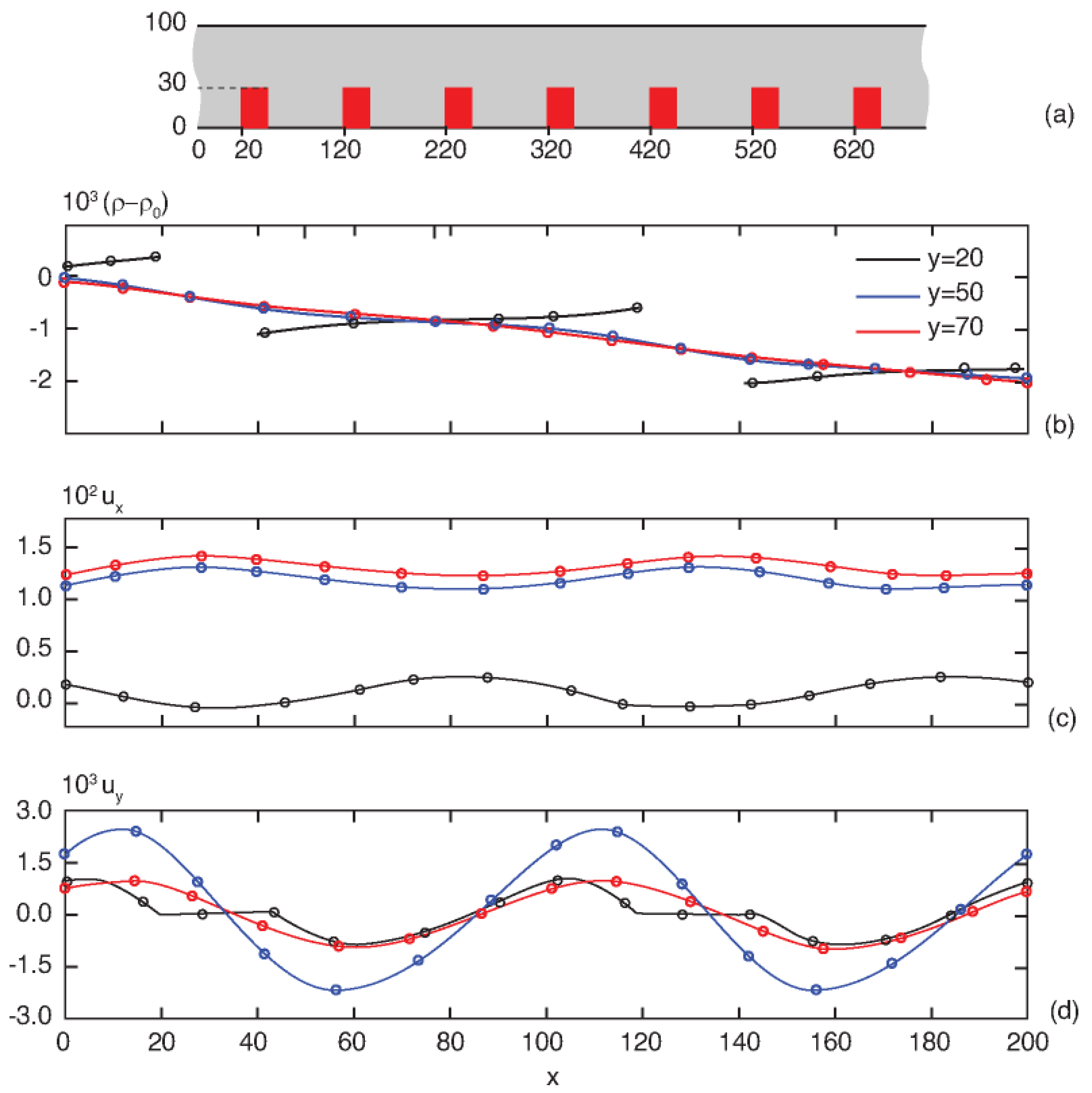
The simulation framework was verified against known analytical and numerical benchmarks. Steady Poiseuille channel flow reproduced the expected parabolic velocity profile and volumetric flux. The effectiveness of the sponge outlet was evaluated by monitoring reflected wave amplitudes, which remained below 1–2% of the incident signal. For the non-oscillating inlet, results were cross-checked with published LBM benchmarks for porous media with spatial periodicity [28]. Rectangular obstacles, shown in Figure 3a, were selected for this benchmarking case. Figure 3b–d compare the computed density differences and velocity components at several transverse positions with the data reported in [28] using periodic boundary conditions, demonstrating close agreement.

2.6. Grid and Time-Step

To ensure that the numerical results were independent of spatial discretization, a grid-refinement study was performed for the representative case of a rectangular-obstacle channel at porosity ϕ =   0.85 and oscillation amplitude ρ =   0.05 . Three uniform lattices were tested with characteristic channel heights of H   =   80 ,   100 , and 120 lattice nodes, while maintaining the same geometric ratios and dimensionless parameters. The lattice spacing was set to Δ x   =   1 and the time step to Δ t   =   1 in lattice units.
The cycle-averaged volumetric flow rate and its ratio to the corresponding steady-state value were monitored over several pulsation periods after reaching steady periodic conditions. The variation in the normalized flow rate between the two finest grids ( H   =   100 and 120 ) was found to be less than 1.5 % across all frequencies examined, indicating satisfactory grid convergence. The coarsest grid ( H   =   80 ) produced slightly larger deviations (≈ 3%) near resonance peaks but preserved the overall trends.
All subsequent simulations were conducted with H   =   100 ,   Δ x   =   Δ t   =   1 , and τ   =   1.0 , providing an optimal balance between accuracy and computational cost. Under these settings, the maximum Mach number remained below 0.05, ensuring a weakly compressible, laminar flow consistent with the LBM assumptions.
Table 1 summarizes the numerical parameters and convergence verification results used in this work.

3. Results

3.1. Definition of Quantitative Metrics

To quantify the influence of pulsatile inlet pressure on the flow rate, the volumetric flux was cycle-averaged over last K pulsation periods after achieving steady periodic conditions:
Q ¯ = Q x , t ,
Q x , t = 0 H u x x , y , t d y ,
where the angle brackets denote temporal averaging. The quantity Q ¯ was evaluated at a fixed streamwise location within the domain, selected from the region where longitudinal periodicity is preserved. The choice of the exact cross-sectional location does not alter the magnitude of Q ¯ , with an accuracy of 0.1%. Normalizing time-averaged flow rate by its corresponding steady-state value yields the dimensionless frequency response R ω = Q ¯ / Q s t e a d y , which represents the ratio of cycle-averaged pulsatile flow to the equivalent steady flow under identical mean driving pressure.
Simulations were performed for multiple obstacle geometries—rectangular, triangular, circular, and elliptical—with porosities ϕ = 0.85 and ϕ = 0.90 and inlet oscillation amplitudes ρ   =   0.05 and ρ   =   0.10 . Each case was run for at least 40 oscillation periods to ensure convergence; the cycle-averaged flux varied by less than 0.05% when the averaging interval was doubled, confirming numerical stability. So, the number of oscillation periods K = 3 is adopted for consistency.

3.2. Frequency Dependence of Flow Rate

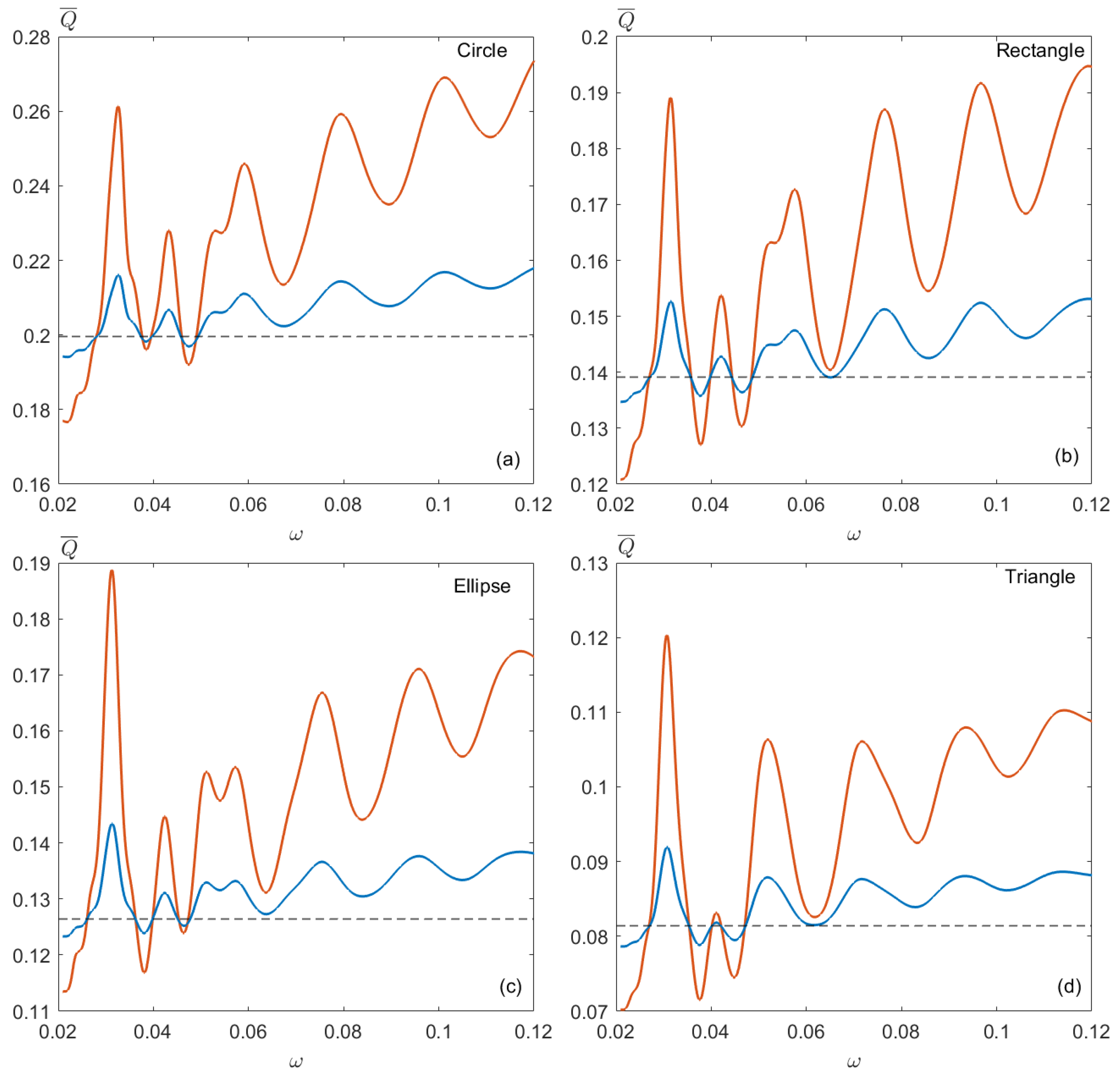
Figure 4 shows the dependence of the cycle-averaged volumetric flow rate on the pulsation frequency for different shapes of obstacles. The obstacles dimensions are selected so that porosity ϕ = 0.85 . Rectangular obstacles have a width of 30 and height of 50; circular obstacles have a diameter of 43.7; elliptical obstacles have a width of 30.3 and height of 63; and triangular obstacles have a base width of 42.4 and height of 70.7. Rectangular, circular, and elliptical obstacles are centered vertically at the channel midline, while triangular obstacles are positioned 20 lattice units above the channel bottom.
All obstacle shapes exhibit a non-monotonic response with alternating enhancement and suppression bands, indicating a coupling between temporal pulsation and the spatial periodicity of the pore geometry.
At low frequencies, the flow rate approaches the steady-state value, as the fluid has sufficient time to adjust to the pressure variations. As the frequency increases, Q ¯ displays distinct maxima and minima corresponding to resonance-like conditions. The first enhancement peak typically occurs near dimensionless frequency ω   0.03 (in lattice units), where Q ¯ exceeds the steady value by 10–50%, depending on geometry. Increasing the oscillation amplitude from ρ   =   0.05 to ρ   =   0.10 amplifies the response magnitude but does not shift the positions of the extrema, suggesting a predominantly linear response regime.

3.3. Effect of Porosity

Figure 5 shows the flow rates for a channel with higher porosity. The obstacle dimensions are proportionally scaled relative to those in Figure 4 to maintain ϕ = 0.90 . As seen in the figure, the magnitude of flow enhancement becomes more pronounced. Such behavior arises from reduced viscous dissipation and stronger effective coupling between the oscillation period and pore-scale flow structures. The enhancement peaks also become sharper, indicating higher sensitivity to frequency variation.
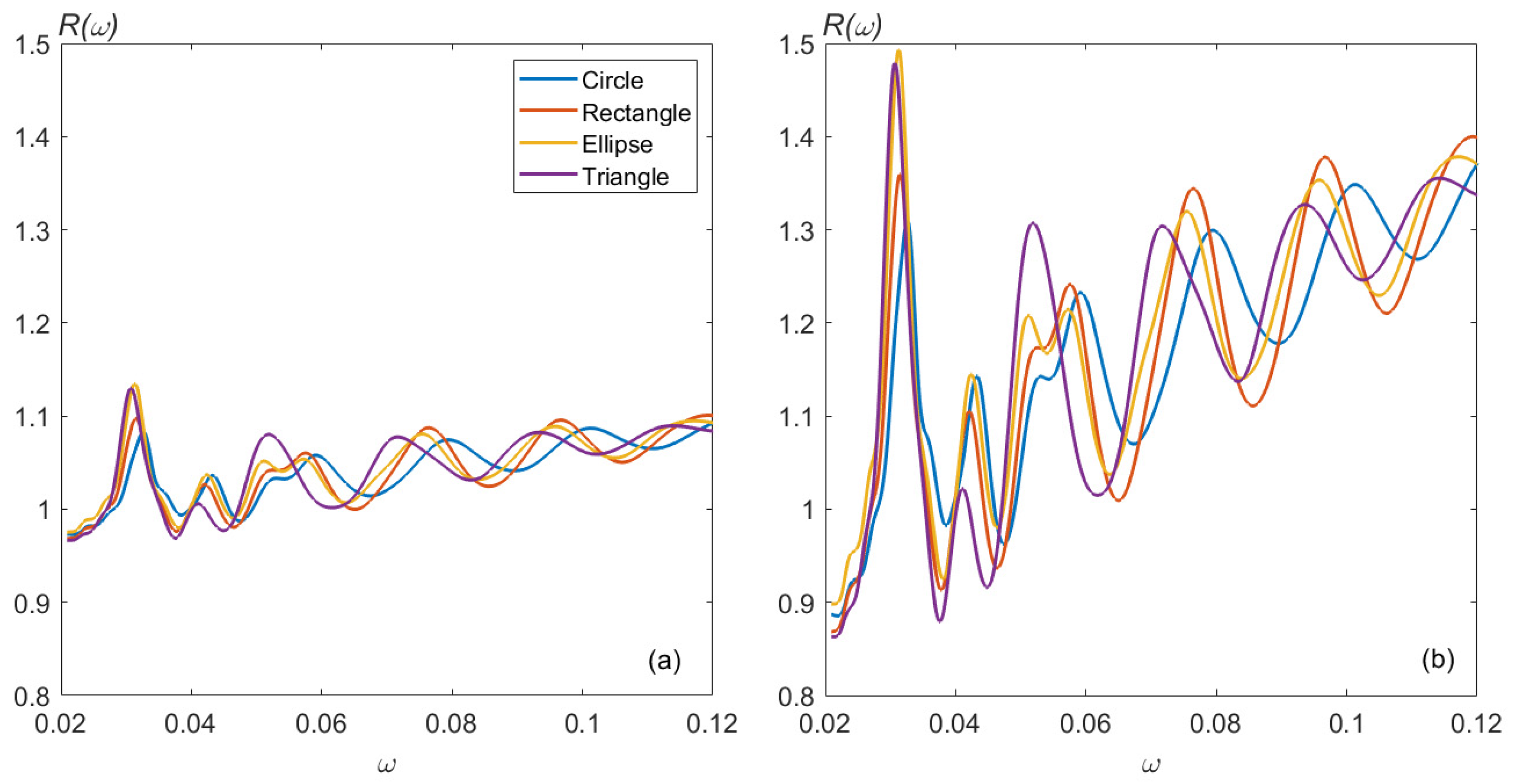
The corresponding frequency response curves (Figure 6) collapse more closely at low frequencies, where inertial effects are negligible and diverge at higher frequencies as geometry-dependent inertial recirculation emerges.

3.4. Influence of Obstacle Geometry

For a given porosity, the obstacle shape significantly affects the amplitude of the frequency response. Triangular barriers exhibit the lowest mean flow rate due to their larger local blockage and sharper corners that induce stagnant zones. In contrast, circular and elliptical shapes facilitate smoother streamlines and stronger pulsation-induced transport.
Table 2 summarizes the maximal values R max of the frequency response measured at the first resonance frequencies ( ω = 0.032 for circular and ω = 0.031 for the other obstacle types). The results indicate that, although elliptical and triangular obstacles yield lower steady-state flow rates due to their higher blockage ratios, they exhibit the strongest amplification under pulsatile forcing. Specifically, R max reaches 1.69 for elliptical geometries and 1.56 for triangular geometries at Δ ρ = 0.1 , exceeding the corresponding enhancement for circular (1.43) and rectangular (1.48) configurations. The increase in response with higher forcing amplitude ( Δ ρ = 0.1 ) and lower porosity ( ϕ = 0.85 ) further confirms that geometric constriction enhances the sensitivity of the flow to oscillatory pressure variations.
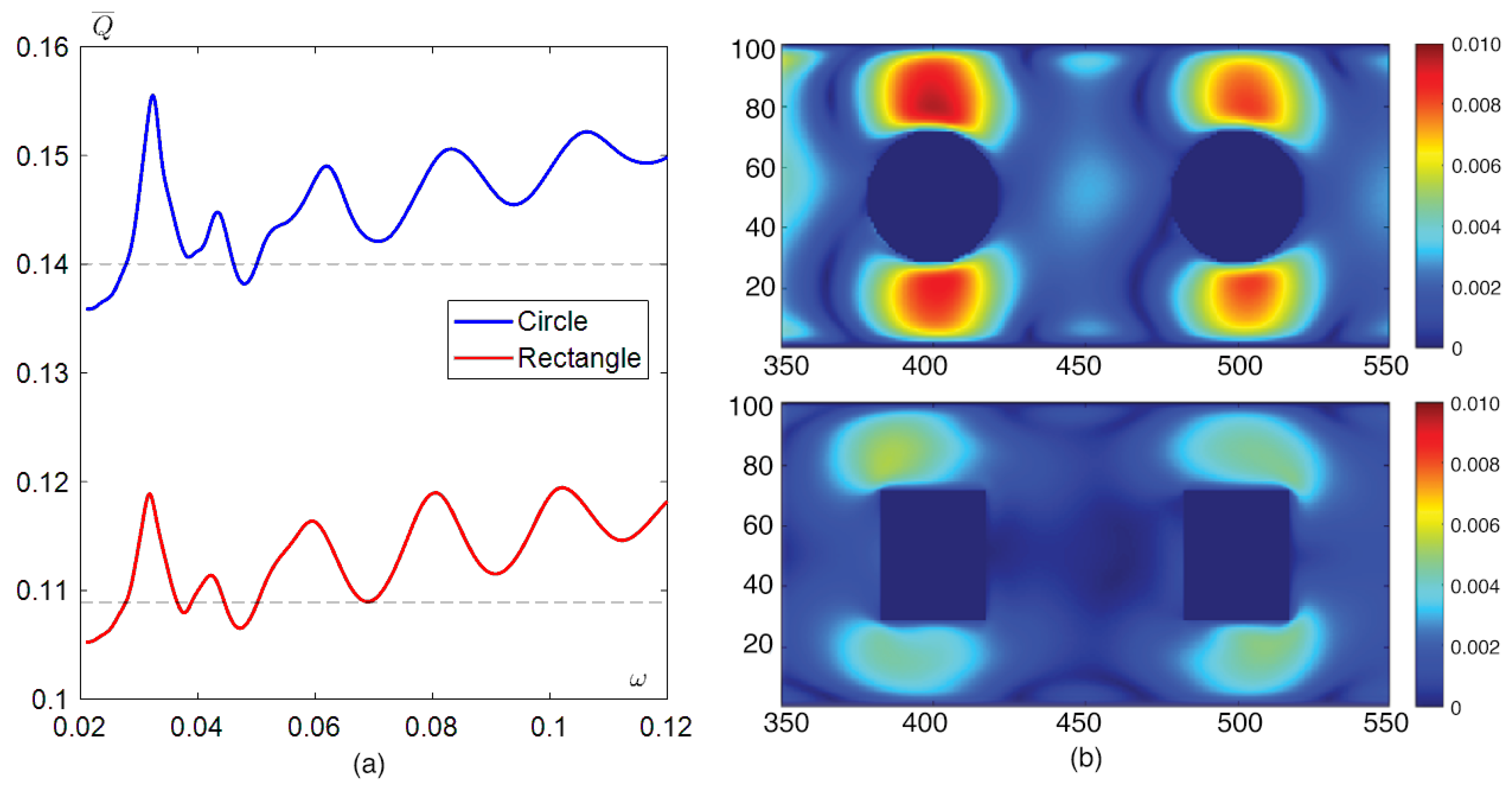
Figure 7 compares circular and rectangular obstacles with an identical blockage ratio ( β 0.44 ). The two representative geometries display nearly coincident resonance frequencies, confirming that periodicity primarily determines the response enhancement condition, while shape influences the magnitude of the enhancement. At the first peak, circular obstacles yield approximately 1.5 × larger throughput than rectangular ones. The instantaneous velocity fields (Figure 7b) show that circular obstacles generate wider shear layers and stronger downstream acceleration, consistent with their higher effective permeability under oscillatory forcing.

3.5. Effect of Blockage Ratio and Obstacle Position

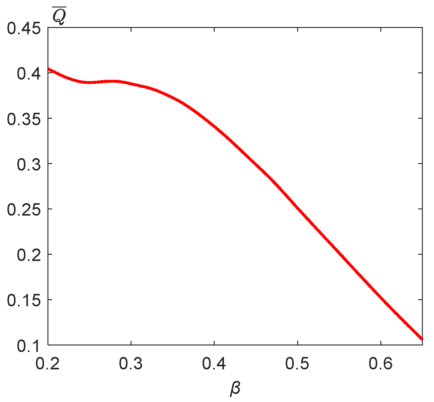
Figure 8 illustrates the variation in the cycle-averaged flow rate with blockage ratio β for elliptical obstacles at a fixed porosity ϕ =   0.85 and dimensionless frequency ω   0.03 . Increasing β leads to a nearly monotonic decrease in Q ¯ , indicating that geometric constriction dominates over pulsation-driven enhancement when solid fractions become large.
Complementary results for rectangular obstacles with varying aspect ratios but constant porosity (Figure 9) reveal that the spacing between obstacles also modulates the response. Narrower spacing enhances the hydrodynamic interaction between consecutive wakes, slightly shifting peak frequencies toward higher values. These results confirm that both the blockage ratio and the streamwise periodicity jointly control the optimal pulsation conditions.
In the canonical Womersley solution, the transition between viscous and inertial regimes is determined by the dimensionless number α   = D ω / 2 π ν (for characteristic size D ), and the velocity-phase lag and amplitude attenuation follow Bessel-function formalism [22]. In our pseudo-periodic geometry, the analogous dimensionless frequency metric can be defined via obstacle size/spacing and kinematic viscosity, and we observe resonance peaks at α     10 , consistent with the viscous–inertial transition in analytical solutions. The more complex geometry adds additional damping/recirculation not captured in the simpler solutions [23,24].

4. Conclusions

This study investigated pulsation-enhanced transport in pseudo-periodic porous channels using a two-dimensional D2Q9 lattice Boltzmann framework with sinusoidal inlet pressure forcing. By systematically varying porosity, obstacle geometry, and pulsation frequency, we quantified the dynamic response of the flow and identified conditions under which time-periodic forcing enhances net throughput relative to steady flow.
The results reveal that periodic inlet pulsation can substantially modify pore-scale transport. The cycle-averaged volumetric flux exhibits non-monotonic dependence on frequency, with well-defined enhancement and suppression bands—akin to resonance behavior. The first resonance typically occurs near the dimensionless frequency ( ω   0.03 ), yielding up to 50% higher flow rates than under steady conditions. The position of resonance peaks depends primarily on the geometric periodicity ( L p ) and porosity ( ϕ ), whereas the obstacle shape modulates the amplitude of the response: circular and elliptical geometries promote smoother streamline transition and stronger enhancement, while triangular obstacles induce local stagnation and lower effective transport.
The findings confirm that temporal pulsation and spatial periodicity can interact constructively to increase effective permeability, extending earlier observations by Womersley [13] for straight channels and by Chen et al. [21] for hierarchical porous layers to a broader class of pseudo-periodic systems. The proposed dimensionless frequency-response function ( R ω = Q ¯ / Q s t e a d y ) provides a useful metric for comparing unsteady flow regimes across geometries and operating conditions.
Beyond elucidating the fundamental mechanism of pulsation-induced enhancement, this work establishes a reproducible LBM workflow for unsteady porous-medium simulations, including robust pressure boundary treatment and sponge-layer stabilization. The results offer practical guidance for designing pulsation-assisted processes in biomedical microcirculation, oscillatory filtration, and cyclic-injection EOR systems, where throughput or mixing efficiency can be optimized through appropriate tuning of forcing frequency and pore geometry.
Although the present model is two-dimensional, it captures the essential coupling between temporal pulsation and spatial periodicity. Similar trends are expected in 3D configurations where tortuosity adds additional damping modes. Extending the study to 3D will allow assessment of transverse connectivity and pore-network anisotropy, which may shift resonance frequencies but not the overall enhancement mechanism.
Future studies will also extend this framework to multiphase configurations, where additional resonance modes and interfacial effects are expected to emerge. Such analyses will further clarify how pulsation-driven transport can be exploited for flow control and optimization in complex porous architectures.

Author Contributions

Conceptualization, I.N.; Software, K.T.; Validation, I.N. and K.T.; Formal analysis, I.N.; Investigation, K.T.; Writing—original draft, I.N. and K.T.; Writing—review & editing, I.N.; Visualization, K.T.; Funding acquisition, K.T. All authors have read and agreed to the published version of the manuscript.

Funding

This research was funded by Shota Rustaveli National Science Foundation of Georgia (SRNSFG), grant# FR-22-6666, project title: “Interdisciplinary study of fluid flow in porous material through multiphase numerical simulation and experiment”.

Institutional Review Board Statement

Not applicable.

Informed Consent Statement

Not applicable.

Data Availability Statement

The original contributions presented in this study are included in the article. Further inquiries can be directed to the authors.

Acknowledgments

During the preparation of this manuscript, the authors used ChatGPT 5 for the purpose of editing the text.

Conflicts of Interest

The authors declare no conflicts of interest.

References

  1. Blunt, M.J. Multiphase Flow in Permeable Media: A Pore-Scale Perspective; Cambridge University Press: Cambridge, UK, 2017. [Google Scholar]
  2. Das, M.K.; Mukherjee, P.P.; Muralidhar, K. Modeling Transport Phenomena in Porous Media with Applications; Springer International Publishing: Berlin/Heidelberg, Germany, 2018. [Google Scholar] [CrossRef]
  3. Nield, D.A.; Bejan, A. Mechanics of Fluid Flow Through a Porous Medium; Springer: Berlin/Heidelberg, Germany, 2013. [Google Scholar] [CrossRef]
  4. Secomb, T.W. Blood Flow in the Microcirculation. Annu. Rev. Fluid Mech. 2017, 49, 443–461. [Google Scholar] [CrossRef]
  5. Pries, A.R.; Secomb, T.W. Making Microvascular Networks Work: Angiogenesis, Remodeling, and Flow Control. Nat. Rev. Physiol. 2022, 1, 1–17. [Google Scholar] [CrossRef]
  6. Yang, H.; Lao, J.; Tong, D.; Song, H. Numerical Investigation on EOR in Porous Media by Cyclic Water Injection with Vibration Frequency. Water 2022, 14, 3961. [Google Scholar] [CrossRef]
  7. Song, S.; Wang, S.; Le-Clech, P.; Shen, Y. LBM-DEM simulation of particle deposition and resuspension of pre-deposited dynamic membranes. Sep. Purif. Technol. 2022, 295, 121222. [Google Scholar] [CrossRef]
  8. D’Orazio, A.; Karimipour, A.; Ranjbarzadeh, R. Lattice Boltzmann Modelling of Fluid Flow through Porous Media: A Comparison between Pore-Structure and Representative Elementary Volume Methods. Energies 2023, 16, 5354. [Google Scholar] [CrossRef]
  9. Hu, Y.; Li, D.; Shu, S.; Niu, X. Finite-volume method with lattice Boltzmann flux scheme for incompressible porous media flow at the representative-elementary-volume scale. Phys. Rev. E 2016, 93, 023308. [Google Scholar] [CrossRef]
  10. Succi, S. The Lattice Boltzmann Equation: For Complex States of Flowing Matter; Oxford Academic: Oxford, UK, 2018. [Google Scholar] [CrossRef]
  11. Liu, X.; Zhu, Y.-F.; Gong, B.; Yu, J.-P.; Cui, S.-T. From molecular dynamics to lattice Boltzmann: A new approach for pore-scale modeling of multi-phase flow. Pet. Sci. 2015, 12, 282–292. [Google Scholar] [CrossRef]
  12. Krüger, T.; Kusumaatmaja, H.; Kuzmin, A.; Shardt, O.; Silva, G.; Viggen, E.M. The Lattice Boltzmann Method: Principles and Practice; Springer: Cham, Switzerland, 2017. [Google Scholar] [CrossRef]
  13. Womersley, J.R. Method for the calculation of velocity, rate of flow and viscous drag in arteries when the pressure gradient is known. J. Physiol. 1955, 127, 553–563. [Google Scholar] [CrossRef]
  14. Biot, M.A. Theory of propagation of elastic waves in a fluid-saturated porous solid. I. Low frequency range. J. Acoust. Soc. Am. 1956, 28, 168–178. [Google Scholar] [CrossRef]
  15. Biot, M.A. Theory of propagation of elastic waves in a fluid-saturated porous solid. II. Higher frequency range. J. Acoust. Soc. Am. 1956, 28, 179–191. [Google Scholar] [CrossRef]
  16. Johnson, D.L.; Koplik, J.; Dashen, R. Theory of dynamic permeability and tortuosity in fluid-saturated porous media. J. Fluid Mech. 1987, 176, 379–402. [Google Scholar] [CrossRef]
  17. Cortis, A.; Smeulders, D.M.; Guermond, J.L.; Lafarge, D. Influence of pore roughness on high-frequency permeability. Phys. Fluids 2003, 15, 1766–1775. [Google Scholar] [CrossRef]
  18. Langlois, V. High-frequency permeability of porous media with thin constrictions. I. Wedge-shaped porous media. Phys. Fluids 2022, 34, 077119. [Google Scholar] [CrossRef]
  19. Champoux, Y.; Allard, J.F. Dynamic tortuosity and bulk modulus in air-saturated porous media. J. Appl. Phys. 1991, 70, 1975–1979. [Google Scholar] [CrossRef]
  20. Chapman, A.M.; Higdon, J.J.L. Oscillatory Stokes flow in periodic porous media. Phys. Fluids 1992, 4, 2099–2116. [Google Scholar] [CrossRef]
  21. Chen, S.M.; Hong, B.S.; Shyu, S.H. A Numerical Investigation of Sinusoidal Flow in Porous Media with a Simple Cubic Beam Structure at 1 Hz and 100 Hz Under Different Porosity Conditions. Fluids 2025, 10, 126. [Google Scholar] [CrossRef]
  22. Berselli, L.C.; Miloro, P.; Menciassi, A.; Sinibaldi, E. Exact solution to the inverse Womersley problem for pulsatile flows in cylindrical vessels, with application to magnetic particle targeting. Appl. Math. Comp. 2013, 219, 5717–5729. [Google Scholar] [CrossRef]
  23. Manopoulos, C.; Raptis, A.; Tsangaris, S. Analytical Solution of Oscillatory Stokes Flow in a Porous Pipe with Spatiotemporally Periodic Suction/Injection. Appl. Mech. 2022, 3, 683–691. [Google Scholar] [CrossRef]
  24. Sobhnamayan, F.; Sarhaddi, F.; Behzadmehr, A. Analytical solution of pulsating flow and forced convection heat transfer in a pipe filled with porous medium. J. Comp. Appl. Mech. 2021, 52, 570–587. [Google Scholar] [CrossRef]
  25. Bhatnagar, P.L.; Gross, E.P.; Krook, M. A model for collision processes in gases. I. Small amplitude processes in charged and neutral one-component systems. Phys. Rev. 1954, 94, 511–525. [Google Scholar] [CrossRef]
  26. Qian, Y.H.; d’Humières, D.; Lallemand, P. Lattice BGK models for Navier–Stokes equation. Europhys. Lett. 1992, 17, 479–484. [Google Scholar] [CrossRef]
  27. Zou, Q.; He, X. On pressure and velocity boundary conditions for the lattice Boltzmann BGK model. Phys. Fluids 1997, 9, 1591. [Google Scholar] [CrossRef]
  28. Zhang, H.; Kwok, D.Y. Pressure boundary condition of the lattice Boltzmann method for fully developed periodic flows. Phys. Rev. E 2006, 73, 047702. [Google Scholar] [CrossRef] [PubMed]
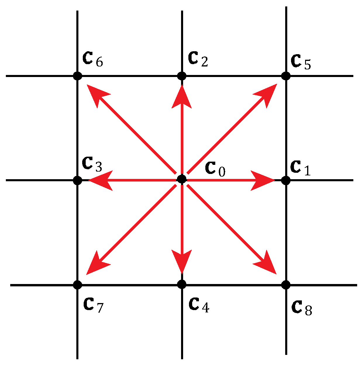
Figure 1. Lattice velocity set in D2Q9.
Fluids 10 00299 g001
Figure 2. Problem geometry. Pseudo-periodic array of obstacles repeated along the streamwise direction.
Fluids 10 00299 g002
Figure 3. Arrangement of rectangular obstacles in the channel (a), spatial dependence of (b) density difference ρ ρ 0 , (c) streamwise velocity u x , and (d) transverse velocity u y along the x-coordinate. Black, blue, and red curves correspond to y = 20 ,   y = 50 , and y = 70 , respectively. Solid lines denote reference results from [25], while circles indicate the present calculations.
Fluids 10 00299 g003
Figure 4. Pulsation-driven flow rate dependence on pulsation period for different obstacle shapes: (a) circular, (b) rectangular, (c) elliptical, and (d) triangular. The overall channel porosity is ϕ = 0.85 . Red and blue curves correspond to different inlet oscillation amplitudes of ρ = 0.1 and ρ = 0.05 , respectively. Horizontal dashed lines correspond to steady flow rates, Q s t e a d y .
Fluids 10 00299 g004
Figure 5. Pulsation-driven flow rate dependence on pulsation period for different obstacle shapes: (a) circular, (b) rectangular, (c) elliptical, and (d) triangular. The overall channel porosity is ϕ = 0.90 . Red and blue curves correspond to different inlet oscillation amplitudes of ρ = 0.1 and ρ = 0.05 , respectively. Horizontal dashed lines correspond to steady flow rates, Q s t e a d y .
Fluids 10 00299 g005
Figure 6. Frequency response R ω for amplitudes ρ = 0.05 (a) and ρ = 0.1 (b). Porosity is ϕ = 0.90 .
Fluids 10 00299 g006
Figure 7. (a) Dependence of the cycle-averaged flow rate Q ¯ on the pulsation frequency. Circular and rectangular obstacles are presented as representative cases to avoid redundancy; The inlet oscillation amplitude ρ = 0.05 ; the porosity ϕ =   0.85 ; horizontal reference lines indicate the steady-flow rates Q s t e a d y ; (b) instantaneous velocity distributions for circular and rectangular obstacles shown over a representative fragment of the channel. The obstacles are centered vertically at the channel midline.
Fluids 10 00299 g007
Figure 8. Dependence of the flow rate on the blockage ratio β . The obstacles are elliptic, vertically centered at the channel midline, with semiaxes chosen to maintain a porosity of ϕ = 0.85 ; pulsation frequency ω = 0.0314 corresponds to period T = 200 .
Fluids 10 00299 g008
Figure 9. Flow rate for rectangular obstacles with different blockage ratios β but with the same porosity, ϕ = 0.85 . The inlet density amplitude is ρ = 0.1 .   The obstacle dimensions are indicated in each sub-figure: (a) 20 × 75, (b) 30 × 50, (c) 50 × 30, and (d) 75 × 20. The rectangular obstacles are positioned 5 lattice units above the lower channel wall.
Fluids 10 00299 g009
Table 1. Simulation parameters.
ParameterSymbolTested Values/SettingsDescription/Remarks
Channel height (lattice nodes) H 80, 100, 120Defines grid resolution in the transverse direction
Channel length (lattice nodes)1000Ensures pseudo-periodicity and developed resonance response
Length of obstacle unit cell L p 100
Lattice spacing Δ x 1 (lattice unit)Spatial discretization step
Time step Δ t 1 (lattice unit)Temporal discretization step
Relaxation time τ 1Adjusted to preserve kinematic viscosity
Kinematic viscosity ν c s 2 τ 0.5 Δ t = 1 / 6 Maintained constant across tests
Porosity (reference case)ϕ0.85, 0.9Representative test configuration
Oscillation amplitude ρ 0.05, 0.1Dimensionless inlet density amplitude
Number of pulsation periods for averaging K 3Ensures stable averaged value of flow rate
Maximum Mach number<0.05Ensures weakly compressible, laminar regime
Table 2. Frequency response R ω for different conditions.
Obstacle Shape ϕ = 0.85 ϕ = 0.90
ρ = 0.05 ρ = 0.1 ρ = 0.05 ρ = 0.1
Circular1.111.431.081.31
Rectangular1.131.481.091.36
Elliptical1.191.691.141.49
Triangular1.161.561.131.48
Disclaimer/Publisher’s Note: The statements, opinions and data contained in all publications are solely those of the individual author(s) and contributor(s) and not of MDPI and/or the editor(s). MDPI and/or the editor(s) disclaim responsibility for any injury to people or property resulting from any ideas, methods, instructions or products referred to in the content.