Article

Slow Motion of a Spherical Particle Perpendicular to Two Planar Walls with Slip Surfaces

Department of Chemical Engineering, National Taiwan University, Taipei 10617, Taiwan
*
Author to whom correspondence should be addressed.
Fluids 2025, 10(11), 287; https://doi.org/10.3390/fluids10110287
Submission received: 12 September 2025 / Revised: 20 October 2025 / Accepted: 28 October 2025 / Published: 3 November 2025
(This article belongs to the Section Flow of Multi-Phase Fluids and Granular Materials)

Abstract

The quasi-steady creeping flow of a viscous fluid around a slip sphere translating perpendicular to one or two large slip planar walls at arbitrary relative positions is analyzed. To solve the axisymmetric Stokes equation for the fluid flow, we construct a general solution using fundamental solutions in spherical and cylindrical coordinate systems. Boundary conditions are first applied to the planar walls using the Hankel transform and then to the particle surface using a collocation method. Numerical results of the drag force exerted by the fluid on the particle are obtained for different values of the relevant stickiness/slip and configuration parameters. Our force results agree well with existing solutions for the motion of a slip sphere perpendicular to one or two nonslip planar walls. The hydrodynamic drag force acting on the particle is a monotonic increasing function of the stickiness of the planar walls and the ratio of its radius to distance from each planar wall. With other parameters remaining constant, this drag force generally increases with increasing stickiness of the particle surface. The influence of the slip planar walls on the axisymmetric translation of a slip sphere is significantly stronger than its axisymmetric rotation.

1. Introduction

Problems concerning the migration of a colloidal particle in a viscous fluid at low Reynolds numbers have received extensive attention from researchers in the fields of chemical, mechanical, biomedical, civil, and environmental engineering and science. Most such creeping motions are fundamental in nature, providing a basis for understanding numerous practical systems and industrial processes such as sedimentation, flocculation, flotation, aerosol technology, suspension rheology, locomotion of blood cells in arteries or veins, microfluidics, electrophoresis, and other phoretic motions. The theoretical study of this theme began with the classic work of Stokes [1] on the slow translation of a nonslip rigid sphere in an unbounded fluid.
In spite of that, a viscous fluid in contact with a solid surface is normally assumed to be nonslip in the Stokes problems; it can slip frictionally for the flows at lyophobic [2,3,4,5], permeable [6,7], airborne [8,9,10], and other [11,12] solid surfaces. Such slip velocities are presumably proportional to the shear stress of the fluid at the solid surfaces with the Navier slip coefficient β 1 as a proportionality factor [13]. Basset [14] found that the force exerted by the surrounding unbounded fluid of viscosity η on a migrating rigid sphere of radius a with a slip-flow boundary condition at its surface is
F 0 = 6 π η a U β a + 2 η β a + 3 η ,
where U is the translational velocity of the particle. In the particular case of β , there is no slip at the particle surface and Equation (1) degenerates to Stokes’ law. When β = 0 , there is a perfect slip at the particle surface and Equation (1) is consistent with the translation of an inviscid gas bubble.
In most practical applications, particles move in bounded fluids. So, it is important to understand whether the proximity of confining walls significantly affects the migration of a particle in a fluid [15,16]. Through an exact representation in spherical bipolar coordinates, Reed and Morrison [17] and Chen and Keh [18] examined the quasi-steady creeping motion of a rigid sphere normal to an infinite planar wall, where the fluid may slip at the solid surfaces. Later, the migrations of a spherical particle inside a spherical cavity with slip surfaces at an arbitrary direction were analyzed for the concentric case [19,20] and semi-analytically studied with the use of a boundary collocation method [21,22,23,24] for the eccentric case [25,26]. The wall effects experienced by a slip spherical particle migrating along the axis of a slip circular tube [27,28], axisymmetric toward an orifice in a nonslip planar wall [29], as well as at arbitrary position and direction between two parallel nonslip planar walls [30,31] were also examined by using the boundary collocation method. In these investigations with confining walls, analytical and numerical results for the hydrodynamic drag force acting on the slip particle to correct Equation (1) were obtained for various cases.
The purpose of this article is to obtain a solution for the slow translational motion of a slip spherical particle perpendicular to two parallel slip planar walls at an arbitrary position between them. The creeping flow equations applicable to the systems are solved by using the boundary collocation method [23], and the wall-corrected hydrodynamic drag force acting on the particle is obtained with good convergence for various cases.

2. Analysis

As illustrated in Figure 1, we consider the quasi-steady creeping flow of a Newtonian fluid around a spherical particle of radius a translating with velocity U (in the z direction) normal to two large planar walls whose distances from the center of the particle are b and c , respectively (setting b c without loss of generality). The circular cylindrical coordinates ( ρ , ϕ , z ) and spherical coordinates ( r , θ , ϕ ) with their origin at the particle center are used. The fluid may slip frictionally to any degree at the particle and wall surfaces and is at rest away from the particle. The purpose is to determine the correction to Equation (1) for the axisymmetric motion of the slip sphere due to the presence of the slip planar walls.
The fluid flow is governed by the equation of motion
E S 2 ( E S 2 Ψ ) = 0 ,
where Ψ is the Stokes stream function (automatically satisfying the continuity equation of the incompressible fluid) related to the nonvanishing velocity components in cylindrical coordinates by
v ρ = 1 ρ Ψ z ,   v z = 1 ρ Ψ ρ ,
and E S 2 is the Stokes operator given by
E S 2 = ρ ρ ( 1 ρ ρ ) + 2 z 2 .
Since the slip velocities of the fluid at the solid surfaces are proportional to the local shear stresses (equal to ( I n n ) n : τ / β , where τ is the stress tensor, n is the unit vector outwardly normal to the solid surfaces, and I is the unit tensor) [13,14], the boundary conditions for the fluid flow at the particle surface, planar walls, and infinity are
r = a :   v ρ = 1 β τ r θ cos θ ,   v z = U 1 β τ r θ sin θ ,
z = b :   v ρ = 1 β w 1 τ z ρ ,   v z = 0 ,
z = c :   v ρ = 1 β w 2 τ z ρ ,   v z = 0 ,
ρ   and   b < z < c :   v ρ = v z = 0 ,
where 1 / β and 1 / β w i (with i = 1 and 2) are the Navier slip coefficients about the particle surface and related planar walls, respectively, and τ r θ and τ z ρ are the matching shear stresses of the viscous fluid flow.
The stream function can be expressed as [23]
Ψ = n = 2 ( B n r n + 1 + D n r n + 3 ) G n 1 / 2 ( cos θ ) + 0 F ( ω , z ) ρ J 1 ( ω ρ ) d ω ,
where the transformed function
F ( ω , z ) = A ( ω ) e ω z + B ( ω ) e ω z + C ( ω ) ω z e ω z + D ( ω ) ω z e ω z ,
G n 1 / 2 is the Gegenbauer polynomial of the first kind of order n and degree 1 / 2 , J n is the Bessel function of the first kind of order n , boundary condition (8) is satisfied immediately, B n , D n , A ( ω ) , B ( ω ) , C ( ω ) , and D ( ω ) are the unknown coefficients to be determined from the remaining boundary conditions, and ω is a separation (transform) variable. The infinite-series term in Equation (9) is a general solution to Equation (2) in spherical coordinates denoting the disturbance caused by the spherical particle and the Fourier-Bessel integral term is a general solution to Equation (2) in cylindrical coordinates representing the disturbance shaped by the planar walls. The substitution of Equation (9) into Equation (3) leads to
v ρ = n = 2 [ B n B n ( ρ , z ) + D n D n ( ρ , z ) ] + 0 E ( ω , z ) J 1 ( ω ρ ) ω d ω ,
v z = n = 2 [ B n B n ( ρ , z ) + D n D n ( ρ , z ) ] 0 F ( ω , z ) J 0 ( ω ρ ) ω d ω ,
where
E ( ω , z ) = A ( ω ) e ω z B ( ω ) e ω z + C ( ω ) ( 1 + ω z ) e ω z + D ( ω ) ( 1 ω z ) e ω z ,
and the position functions B n ( ρ , z ) , D n ( ρ , z ) , B n ( ρ , z ) , and D n ( ρ , z ) are given by Equations (A1)–(A4) in Appendix A.
The application of boundary conditions (6) and (7) to Equations (11) and (12) gives
0 [ E ( ω , z i ) + ( 1 ) i 2 η ω β w i E * ( ω , z i ) ] J 1 ( ω ρ ) ω d ω = n = 2 [ B n γ i n ( ρ , z i ) + D n δ i n ( ρ , z i ) ] ,
0 F ( ω , z i ) J 0 ( ω ρ ) ω d ω = n = 2 [ B n B n ( ρ , z i ) + D n D n ( ρ , z i ) ] ,
where
E * ( ω , z ) = A ( ω ) e ω z + B ( ω ) e ω z + C ( ω ) ( 1 + ω z ) e ω z D ( ω ) ( 1 ω z ) e ω z ,
the position functions γ i n ( ρ , z ) and δ i n ( ρ , z ) are given by Equations (A5) and (A6) with i = 1 and 2, z 1 = b , z 2 = c , and η is the viscosity of the fluid. Applying the Hankel transforms on the variable ρ to Equations (14) and (15), we obtain
E ( ω , z i ) + ( 1 ) i 2 η ω β w i E * ( ω , z i ) = n = 2 [ B n S 1 n ( ω , z i ) + D n S 2 n ( ω , z i ) ] ,
F ( ω , z i ) = n = 2 [ B n S 1 n ( ω , z i ) + D n S 2 n ( ω , z i ) ] ,
where the transformed functions S 1 n ( ω , z ) , S 1 n ( ω , z ) , S 2 n ( ω , z ) , and S 2 n ( ω , z ) are given by Equations (A12)–(A15).
After the substitution of Equations (10), (13) and (16), the four linear algebraic equations formed from Equations (17) and (18) with i = 1 and 2 can be solved simultaneously to yield the four coefficients A ( ω ) , B ( ω ) , C ( ω ) , and D ( ω ) in terms of the as yet unknown coefficients B n and D n , with the result
A ( ω ) B ( ω ) C ( ω ) D ( ω ) = n = 2 { B n A 1 n ( ω ) B 1 n ( ω ) C 1 n ( ω ) D 1 n ( ω ) + D n A 2 n ( ω ) B 2 n ( ω ) C 2 n ( ω ) D 2 n ( ω ) } ,
where the functions A i n ( ω ) , B i n ( ω ) , C i n ( ω ) , and D i n ( ω ) with i = 1 and 2 are given by Equations (A40)–(A57).
Substituting Equation (19) back into Equations (10)–(13), we obtain the fluid velocity components as
v ρ = n = 2 [ B n α 1 n ( 1 ) ( r , θ ) + D n α 2 n ( 1 ) ( r , θ ) ] ,
v z = n = 2 [ B n α 1 n ( 2 ) ( r , θ ) + D n α 2 n ( 2 ) ( r , θ ) ] ,
where the position functions α i n ( j ) ( r , θ ) with i and j equal to 1 and 2 are given by Equations (A9) and (A10). The substitution of Equations (20) and (21) into Equation (5) for the boundary condition at the particle surface results in
n = 2 { B n [ α 1 n ( 1 ) ( a , θ ) η β α 1 n * ( a , θ ) cos θ ] + D n [ α 2 n ( 1 ) ( a , θ ) η β α 2 n * ( a , θ ) cos θ ] } = 0 ,
n = 2 { B n [ α 1 n ( 2 ) ( a , θ ) + η β α 1 n * ( a , θ ) sin θ ] + D n [ α 2 n ( 2 ) ( a , θ ) + η β α 2 n * ( a , θ ) sin θ ] } = U ,
where the position functions α i n * ( r , θ ) are given by Equation (A11).
To satisfy the conditions in Equations (22) and (23) along the surface of the slip sphere requires the solution of an infinite array of the coefficients B n and D n . The boundary collocation method [23] enforces these conditions at a number of points on the longitudinal arc from θ = 0 to θ = π of the sphere and truncates their infinite series into finite series. If N points on the longitudinal arc are satisfied and the infinite series are truncated to N terms, we get a system of 2N simultaneous linear algebraic equations. These equations can be solved numerically to obtain the 2N coefficients B n and D n required for the truncated form of Equations (11) and (12) or (20) and (21). Once these coefficients are solved for sufficiently large values of N, the fluid velocity field can be fully obtained.
The drag force exerted by the fluid on the slip sphere can be determined according to [13]
F = 4 π η D 2 .
This formula indicates that only the first coefficient D 2 contributes to the hydrodynamic force on the particle.

3. Results and Discussion

The numerical solutions obtained using the boundary collocation method for the hydrodynamic drag force acting on a slip spherical particle translating perpendicular to a single slip planar wall (viz., c ), two equally slipping planar walls with equal distances (viz., β w 2 = β w 1 and c = b ), and one full-slip planar wall and another nonslip planar wall (viz., β w 2 = 0 and β w 1 ) are listed in Table 1, Table 2 and Table 3, respectively, as functions of the dimensionless stickiness/slip parameter β a / η (ranging from 0 to ) of the particle, spacing parameter a / b (ranging from 0 to 1), and parameter β w 1 b / η (ranging from 0 to ) or b / ( b + c ) (ranging from 0 to 1/2). The drag force F 0 acting on a particle in an unbounded fluid is given by Equation (1), which normalizes the wall-corrected drag force F . Therefore, in the limiting case of a / b = 0 (the plane walls are at infinity), F / F 0 = 1 , regardless of other parameters. Our results for F / F 0 , which are always greater than unity, converge to at least the significant figures shown in the tables, and the number of collocation points N = 200 is sufficiently large to achieve this convergence (the convergence data for the force at different N values are very similar to those given by Ganatos et al. [23]). In the limit β w i b / η , these results agree excellently (to the same significant figures) with those obtained for the axisymmetric translation of a slip particle between two parallel nonslip planar walls [31]. For the cases of a slip sphere translating perpendicular to a no-slip or slip plane wall, our results of F / F 0 are also in good agreement with other analytical and numerical solutions [32,33,34,35].
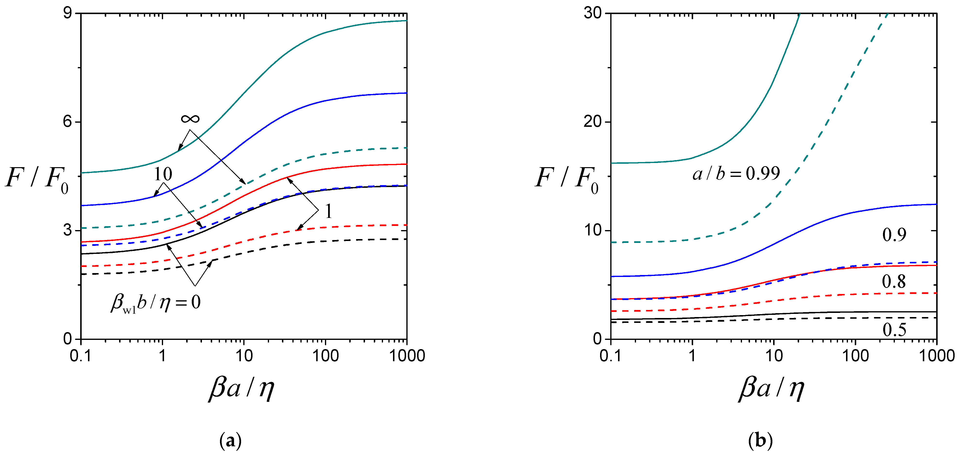
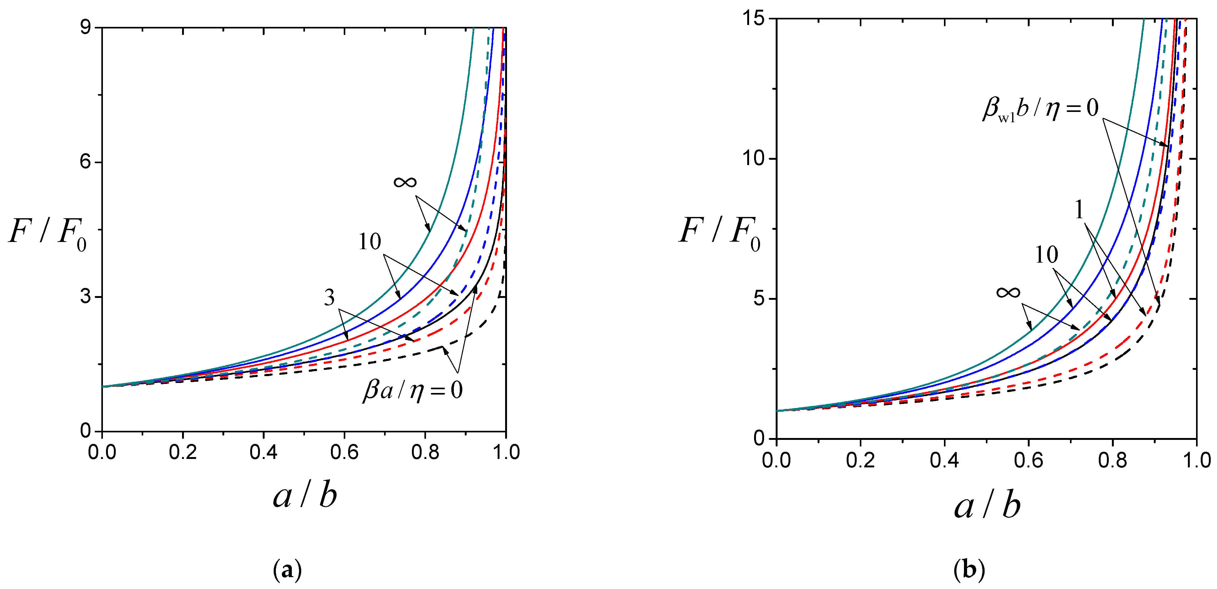
The boundary collocation results of the normalized drag force F / F 0 on a slip sphere translating perpendicular to two equally slipping planar walls with equal distances ( β w 2 = β w 1 and c = b , in solid curves) and to a single planar wall ( c , in dashed curves) versus the parameters β w 1 b / η , β a / η , and a / b are plotted in Figure 2, Figure 3 and Figure 4, respectively. For given values of the spacing parameter a / b and stickiness parameter β a / η of the particle, as shown in Figure 2, Figure 3a and Figure 4b, the normalized force F / F 0 is a monotonic increasing function of the stickiness parameter β w 1 b / η of the planar walls. For specified values of β w 1 b / η and a / b , the normalized force F / F 0 generally increases with increasing β a / η (with some exceptions for large values of β w 1 b / η and a / b , as shown in Table 1, Table 2 and Table 3), as illustrated in Figure 2b, Figure 3 and Figure 4a. For fixed values of β a / η and β w 1 b / η , the normalized force F / F 0 increases monotonically with increasing a / b and becomes infinite in the limiting case of a / b = 1 (the particle contacts the plane walls), as shown in Figure 2a, Figure 3b and Figure 4.
For any fixed values of the parameters β w 1 b / η , β a / η , and a / b , consistent with the previous results of nonslip planar walls ( β w 1 b / η ) [31], the assumption that the hydrodynamic effect of two planar walls on a translating sphere is simply the sum of the effects of each single wall will overestimate the correction to the drag force acting on the particle. That is, the increase in F / F 0 from unity for the case of two planar walls (as given by Table 2 or the solid curves in Figure 2, Figure 3 and Figure 4) is less than twice as it is for the case of a single planar wall (as given by Table 1 or the dashed curves in Figure 2, Figure 3 and Figure 4). The influence of the slip planar walls on the axisymmetric translation of the slip particle is significantly stronger (can be by as much as several orders of magnitude, depending especially on the value of a / b ) than (but not as complex as) their influence on the axisymmetric rotation of the slip particle [36]. Particularly, the hydrodynamic torque T on the rotating sphere near the confining planes normalized by the torque T 0 of the sphere far from the planes equals unity (the planes behave as an unbounded fluid) at a critical value of the wall stickiness parameter β w 1 b / η close to 1.3 and increases with an increase in β w 1 b / η from a positive value less than unity at perfect slip ( β w 1 b / η = 0 ) to greater than unity at no slip ( β w 1 b / η ). When β w 1 b / η is larger than the critical value, the normalized torque T / T 0 rises with increases of a / b and β a / η . When β w 1 b / η is less than the critical value, oppositely, T / T 0 reduces with increases of a / b and β a / η . Moreover, for fixed values of the parameters β w 1 b / η , β a / η , and a / b , the assumption that the hydrodynamic effect of two planes on a rotating sphere is simply the sum of the effects of each single plane will overestimates/underestimates the correction to the torque acting on the sphere if β w 1 b / η is greater/less than the critical value. Even for the limit that the sphere touches the planes ( a / b = 1 ), T / T 0 is still finite.
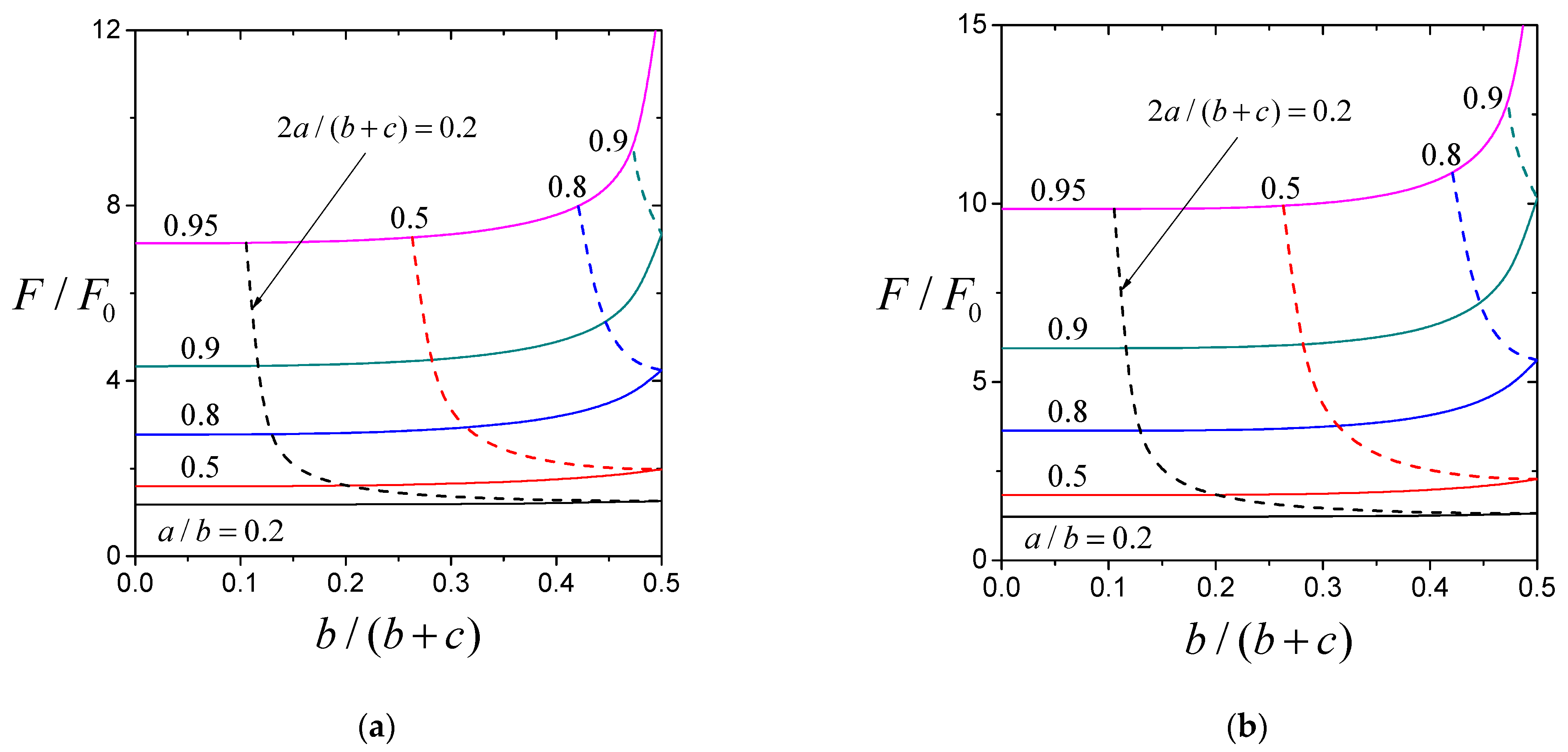
Figure 5 presents the numerical results of the normalized drag force F / F 0 acting on a spherical particle with typical values of the stickiness parameter β a / η translating perpendicular to two equally slipping planar walls ( β w 2 = β w 1 ) versus the ratio b / ( b + c ) (denoting the relative position of the particle between the planar walls). The solid curves (with constant spacing parameter a / b ) illustrate the effect of the position of the second wall (at z = c , where c b ) on the drag force. Obviously, the proximity of a second wall [an increase in b / ( b + c ) ] will enhance the drag force experienced by the particle near the first wall. The dashed curves [with constant ratio of the particle diameter to the wall-to-wall distance 2 a / ( b + c ) ] denote the variation in the drag force as a function of the particle position between the two planar walls. At a constant value of 2 a / ( b + c ) , consistent with the previous results of nonslip planar walls ( β w 1 b / η ) [23,31], when the particle is in the middle between the two planar walls [ b / ( b + c ) = 1 / 2 ], it will experience the minimum drag force, and as the particle approaches either wall, the force increases monotonically.
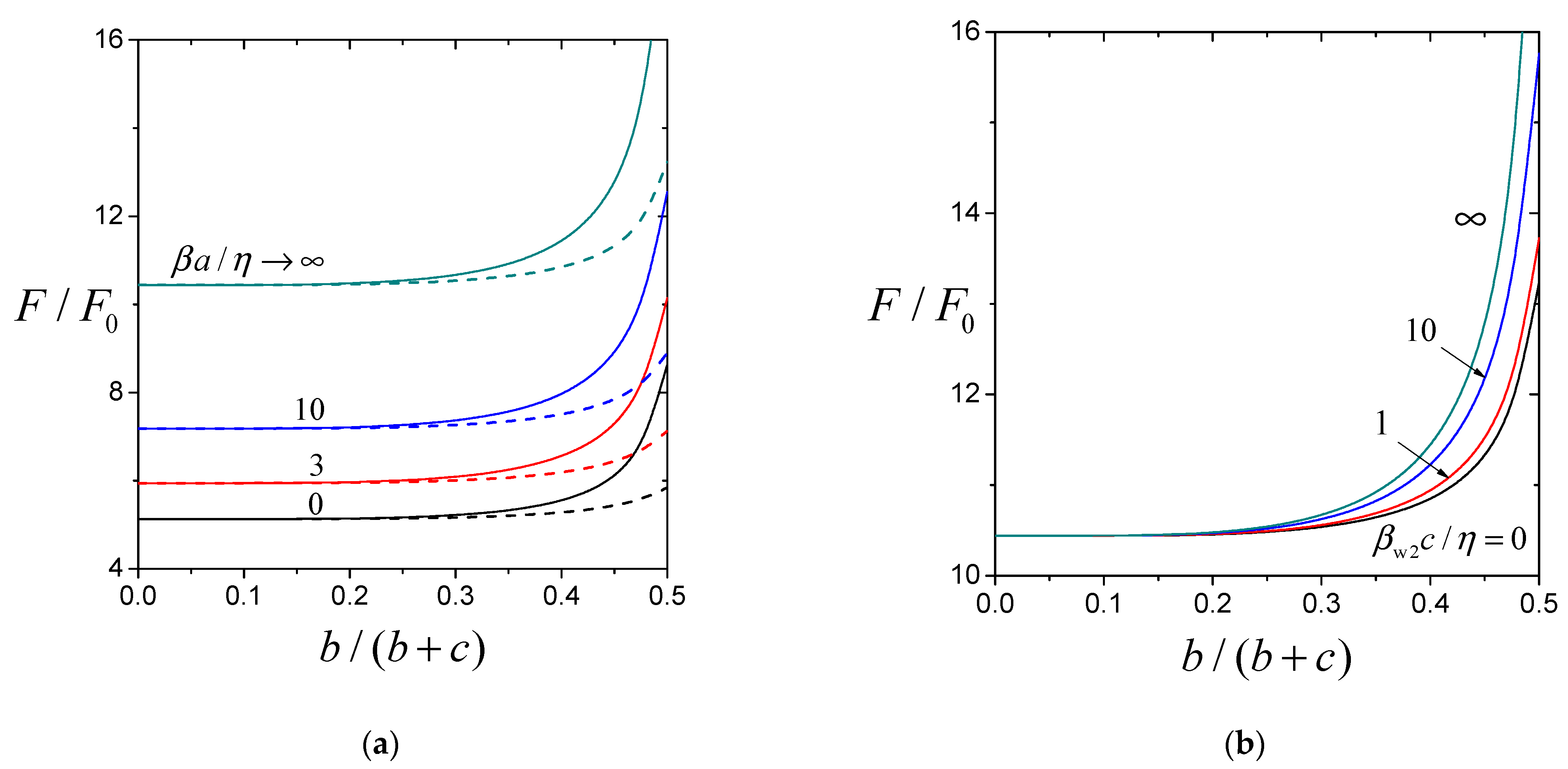
Figure 6a,b present the numerical results of the normalized drag force F / F 0 acting on a spherical particle translating perpendicular to a nonslip planar wall (the first wall with β w 1 b / η ) and another slip plane wall (the second wall) versus the ratio b / ( b + c ) with a / b = 0.9 and various values of the stickiness parameters β a / η and β w 2 c / η , respectively. Again, the proximity of a second wall [an increase in b / ( b + c ) ] will enhance the drag force experienced by the particle near the first wall (which increases with an increase in β a / η ). Naturally, F / F 0 increases with an increase in β w 2 c / η , keeping other parameters unchanged.

4. Concluding Remarks

The slow translation of a slip spherical particle in a viscous fluid perpendicular to two large slip planar walls at any position between them is analyzed. A boundary collocation method is used to solve the axisymmetric Stokes equation for the fluid flow. Numerical results of the drag force F exerted by the fluid on the confined particle normalized by the force F 0 of the particle far from the planar walls are obtained as a function of the scaled particle radius a / b , particle position parameter b / ( b + c ) , particle stickiness parameter β a / η , and planar wall stickiness parameters β w 1 b / η and β w 2 c / η . The normalized drag force F / F 0 is a monotonic increasing function of β w i b / η and a / b . With β w i b / η and a / b remaining constant, F / F 0 generally increases with increasing β a / η .
Section 3 presents results for a resistance problem, in which the drag force F is calculated for a sphere translating perpendicular to two planar walls at a given velocity U [equal to ( F 0 / 6 π η a ) ( β a + 3 η ) / ( β a + 2 η ) according to Equation (1)]. In a mobility problem, on the other hand, the force F [equal to 6 π η a U 0 ( β a + 2 η ) / ( β a + 3 η ) ] applied to a sphere is given, and the wall-corrected velocity U needs to be determined. For the axisymmetric translation of a sphere perpendicular to two planar walls considered here, the ratio U / U 0 for the mobility problem equals the reciprocal of the ratio F / F 0 for the corresponding resistance problem, as shown Table 1, Table 2 and Table 3 and Figure 2, Figure 3, Figure 4, Figure 5 and Figure 6.
The paper only focuses on the motion of a single particle perpendicular to dual slip walls. However, the similar boundary collocation method can be easily used for solving the Stokes problems of actual slip multi-particle systems [18,37,38] and slip particles near other applicable slip boundaries, such as in a spherical cavity [25,26] and circular tube [27]. Also, this research is expected to provide valuable insights for the design of hydrodynamic metamaterials that have emerged in recent years [39,40,41,42].

Author Contributions

Conceptualization, H.J.K.; methodology, H.J.K. and Y.C.C.; investigation, H.J.K. and Y.C.C.; writing—original draft preparation, H.J.K. and Y.C.C.; writing—review and editing, H.J.K.; supervision, H.J.K.; funding acquisition, H.J.K. All authors have read and agreed to the published version of the manuscript.

Funding

This research was funded by the National Science and Technology Council, Taiwan (Republic of China) grant number MOST 113-2221-E-002-063-MY2.

Data Availability Statement

The original contributions presented in this study are included in the article. Further inquiries can be directed to the corresponding author.

Conflicts of Interest

The authors declare no conflicts of interest. The funders had no role in the design of the study; in the collection, analyses, or interpretation of data; in the writing of the manuscript; or in the decision to publish the results.

Appendix A. Some Functions in Section 2

The position functions in Equations (11), (12), (14) and (15) are
B n ( ρ , z ) = ( n + 1 ) ρ ( ρ 2 + z 2 ) n / 2 G n + 1 1 / 2 [ z ( ρ 2 + z 2 ) 1 / 2 ] ,
D n ( ρ , z ) = ( n + 1 ) ρ ( ρ 2 + z 2 ) ( n 2 ) / 2 G n + 1 1 / 2 [ z ( ρ 2 + z 2 ) 1 / 2 ] + 2 z ρ ( ρ 2 + z 2 ) ( n 1 ) / 2 G n 1 / 2 [ z ( ρ 2 + z 2 ) 1 / 2 ] ,
B n ( ρ , z ) = 1 ( ρ 2 + z 2 ) ( n + 1 ) / 2 P n [ z ( ρ 2 + z 2 ) 1 / 2 ] ,
D n ( ρ , z ) = 2 ( ρ 2 + z 2 ) ( n 1 ) / 2 G n 1 / 2 [ z ( ρ 2 + z 2 ) 1 / 2 ] 1 ( ρ 2 + z 2 ) ( n 1 ) / 2 P n [ z ( ρ 2 + z 2 ) 1 / 2 ] ,
γ i n ( ρ , z ) = B n ( ρ , z ) + ( 1 ) i η β w i B n ( ρ , z ) ,
δ i n ( ρ , z ) = D n ( ρ , z ) + ( 1 ) i η β w i D n ( ρ , z ) ,
where P n is the Legendre polynomial of the first kind of order n,
B n ( ρ , z ) = 2 ( n + 1 ) ρ ( ρ 2 + z 2 ) ( n + 2 ) / 2 { ( 2 n + 1 ) z G n + 1 1 / 2 [ z ( ρ 2 + z 2 ) 1 / 2 ] ( n 1 ) ( ρ 2 + z 2 ) 1 / 2 G n 1 / 2 [ z ( ρ 2 + z 2 ) 1 / 2 ] } ,
D n ( ρ , z ) = 2 ρ ( ρ 2 + z 2 ) n / 2 { ( n + 1 ) ( 2 n 3 ) z G n + 1 1 / 2 [ z ( ρ 2 + z 2 ) 1 / 2 ] n ( n 2 ) ( ρ 2 + z 2 ) 1 / 2 G n 1 / 2 [ z ( ρ 2 + z 2 ) 1 / 2 ] } .
The position functions α i n ( j ) ( r , θ ) and α i n * ( r , θ ) with i and j equal to 1 and 2 in Equations (20)–(23) are
α i n ( 1 ) ( r , θ ) =   0   1 M ( ω ) [ G 1 ( ω ) S i n ( ω , b ) + G 2 ( ω ) S i n ( ω , c )
+ G 3 ( ω ) S i n ( ω , b ) + G 4 ( ω ) S i n ( ω , c ) ] J 1 ( ω r sin θ ) ω d ω
r n + 2 i 3 [ ( n + 1 ) G n + 1 1 / 2 ( cos θ ) csc θ 2 ( i 1 ) G n 1 / 2 ( cos θ ) cot θ ] ,
α i n ( 2 ) ( r , θ ) =   0   1 M ( ω ) [ G 5 ( ω ) S i n ( ω , b ) + G 6 ( ω ) S i n ( ω , c )
+ G 7 ( ω ) S i n ( ω , b ) + G 8 ( ω ) S i n ( ω , c ) ] J 0 ( ω r sin θ ) ω d ω
r n + 2 i 3 [ P n ( cos θ ) + 2 ( i 1 ) G n 1 / 2 ( cos θ ) ] ,
α i n * ( r , θ ) = sin 2 θ   0   ω r M ( ω ) [ G 1 ( ω ) S i n ( ω , b ) + G 2 ( ω ) S i n ( ω , c )
+ G 3 ( ω ) S i n ( ω , b ) + G 4 ( ω ) S i n ( ω , c ) ] [ 2 ω r J 0 ( ω r sin θ ) J 1 ( ω r sin θ ) csc θ ] d ω .
+ 2 cos 2 θ   0   1 M ( ω ) [ G 9 ( ω ) S i n ( ω , b ) + G 10 ( ω ) S i n ( ω , c )
+ G 11 ( ω ) S i n ( ω , b ) + G 12 ( ω ) S i n ( ω , c ) ] J 1 ( ω r sin θ ) ω 2 d ω
+ 2 r n + 2 i 4 ( n i ) ( n i + 2 ) G n 1 / 2 ( cos θ ) csc θ ,
where the transformed functions
S 1 n ( ω , z ) = ω n 1 n ! ( z z ) n 1 e ω z [ 1 ( 1 ) i 2 η ω β w i z z ] ,
S 1 n ( ω , z ) = ω n 1 n ! ( z z ) n e ω z ,
S 2 n ( ω , z ) = ω n 3 n ! ( z z ) n 3 [ ( 2 n 3 ) ω z n ( n 2 ) ] e ω z [ 1 ( 1 ) i 2 η ω β w i z z ] ,
S 2 n ( ω , z ) = ω n 3 n ! ( z z ) n [ ( 2 n 3 ) ω z ( n 1 ) ( n 3 ) ] e ω z ,
M ( ω ) = 4 [ sinh τ H 3 ( ω ) τ 2 ] 2 τ ( β 1 + β 2 + β 1 β 2 ) ,
G 1 ( ω ) = 4 [ τ κ cosh σ sinh τ H 7 ( ω ) + τ sinh σ σ cosh κ H 2 ( ω ) ] + 2 κ cosh σ ( β 2 + β 2 ) ,
G 2 ( ω ) = 4 [ τ σ cosh κ sinh τ H 4 ( ω ) + τ sinh κ κ cosh σ H 1 ( ω ) ] 2 σ cosh κ ( β 1 + β 1 ) ,
G 3 ( ω ) = 4 [ τ κ H 4 ( ω ) + σ sinh κ H 3 ( ω ) ] + 2 τ H 4 ( ω ) ( β 2 + β 2 ) ,
G 4 ( ω ) = 4 [ τ σ H 7 ( ω ) + κ sinh σ H 3 ( ω ) ] + 2 τ H 7 ( ω ) ( β 1 + β 1 ) ,
G 5 ( ω ) = 4 [ τ κ sinh σ σ sinh κ H 2 ( ω ) ] 2 κ sinh σ ( β 2 + β 2 ) ,
G 6 ( ω ) = 4 [ τ σ sinh κ κ sinh σ H 1 ( ω ) ] + 2 σ sinh κ ( β 1 + β 1 ) ,
G 7 ( ω ) = 4 [ τ κ H 5 ( ω ) sinh κ H 3 ( ω ) τ H 6 ( ω ) + σ cosh κ H 3 ( ω ) ] ,
G 8 ( ω ) = 4 [ τ σ H 8 ( ω ) sinh σ H 3 ( ω ) τ H 9 ( ω ) + κ cosh σ H 3 ( ω ) ] ,
G 9 ( ω ) = 4 [ τ κ sinh σ sinh τ H 8 ( ω ) + τ cosh σ σ sinh κ H 2 ( ω ) ] + 2 κ sinh σ ( β 2 + β 2 ) ,
G 10 ( ω ) = 4 [ τ σ sinh κ sinh τ H 5 ( ω ) + τ cosh κ κ sinh σ H 1 ( ω ) ] 2 σ sinh κ ( β 1 + β 1 ) ,
G 11 ( ω ) = 4 [ τ κ H 5 ( ω ) + σ cosh κ H 3 ( ω ) ] + 2 τ H 5 ( ω ) ( β 2 + β 2 ) ,
G 12 ( ω ) = 4 [ τ σ H 8 ( ω ) + κ cosh σ H 3 ( ω ) ] + 2 τ H 8 ( ω ) ( β 1 + β 1 ) ,
H 1 ( ω ) = 1 2 ( e τ β 1 + e τ β 1 ) ,
H 2 ( ω ) = 1 2 ( e τ β 2 + e τ β 2 ) ,
H 3 ( ω ) = 1 2 ( e τ β 1 + β 2 + e τ β 1 β 2 ) ,
H 4 ( ω ) = 1 2 ( e σ β 1 + e σ β 1 ) ,
H 5 ( ω ) = 1 2 ( e σ β 1 + + e σ β 1 ) ,
H 6 ( ω ) = 1 2 ( e σ β 1 + β 2 + e σ β 1 β 2 ) ,
H 7 ( ω ) = 1 2 ( e κ β 2 e κ β 2 + ) ,
H 8 ( ω ) = 1 2 ( e κ β 2 + e κ β 2 + ) ,
H 9 ( ω ) = 1 2 ( e κ β 1 β 2 e κ β 1 + β 2 + ) ,
σ = ω ( r cos θ + b ) ,   κ = ω ( r cos θ c ) ,   τ = ω ( b + c ) ,
β i ± = 1 ± 2 η ω β w i .
The functions in Equation (19) are
A i n ( ω ) B i n ( ω ) C i n ( ω ) D i n ( ω ) = 1 M ( ω ) A 1 ( ω ) A 2 ( ω ) A 3 ( ω ) A 4 ( ω ) B 1 ( ω ) B 2 ( ω ) B 3 ( ω ) B 4 ( ω ) C 1 ( ω ) C 2 ( ω ) C 3 ( ω ) C 4 ( ω ) D 1 ( ω ) D 2 ( ω ) D 3 ( ω ) D 4 ( ω ) S i n ( ω , b ) S i n ( ω , c ) S i n ( ω , b ) S i n ( ω , c ) ,
where
1 M ( ω ) A 1 ( ω ) A 2 ( ω ) A 3 ( ω ) A 4 ( ω ) B 1 ( ω ) B 2 ( ω ) B 3 ( ω ) B 4 ( ω ) C 1 ( ω ) C 2 ( ω ) C 3 ( ω ) C 4 ( ω ) D 1 ( ω ) D 2 ( ω ) D 3 ( ω ) D 4 ( ω ) = β 1 e ω b β 1 + e ω b β 1 ( 1 ω b ) e ω b β 1 + ( 1 ω b ) e ω b β 2 + e ω c β 2 e ω c β 2 + ( 1 + ω c ) e ω c β 2 ( 1 + ω c ) e ω c e ω b e ω b ω b e ω b ω b e ω b e ω c e ω c ω c e ω c ω c e ω c 1 ,
or
A 1 ( ω ) = ω b e ω c ( e ω ( b + c ) β 2 + e ω ( b + c ) β 2 ) 2 ω 2 c ( b + c ) e ω b ω c e ω b ( β 2 + β 2 ) ,
A 2 ( ω ) = ω b e ω c ( e ω ( b + c ) β 2 + e ω ( b + c ) β 2 ) + 2 ω 2 c ( b + c ) e ω b + ω c e ω b ( β 2 + β 2 ) ,
A 3 ( ω ) = e ω c ( e ω ( b + c ) e ω ( b + c ) ) β 2 + 2 ω ( b + c ) e ω b ,
A 4 ( ω ) = e ω c ( e ω ( b + c ) e ω ( b + c ) ) β 2 + 2 ω ( b + c ) e ω b ,
B 1 ( ω ) = ω c e ω b ( e ω ( b + c ) β 1 + e ω ( b + c ) β 1 ) 2 ω 2 b ( b + c ) e ω c ω b e ω c ( β 1 + β 1 ) ,
B 2 ( ω ) = ω c e ω b ( e ω ( b + c ) β 1 + e ω ( b + c ) β 1 ) + 2 ω 2 b ( b + c ) e ω c + ω b e ω c ( β 1 + β 1 ) ,
B 3 ( ω ) = e ω b ( e ω ( b + c ) e ω ( b + c ) ) β 1 + 2 ω ( b + c ) e ω c ,
B 4 ( ω ) = e ω b ( e ω ( b + c ) e ω ( b + c ) ) β 1 + 2 ω ( b + c ) e ω c ,
C 1 ( ω ) = ( 1 + ω b ) e ω c ( e ω ( b + c ) β 1 + β 2 + e ω ( b + c ) β 1 β 2 ) + 2 ω ( b + c ) e ω b β 1 + β 2 + + 2 ω 2 c ( b + c ) e ω b β 1 + ,
C 2 ( ω ) = ( 1 + ω b ) e ω c ( e ω ( b + c ) β 1 + β 2 + e ω ( b + c ) β 1 β 2 ) 2 ω ( b + c ) e ω b β 1 β 2 + 2 ω 2 c ( b + c ) e ω b β 1 ,
C 3 ( ω ) = e ω c ( e ω ( b + c ) β 1 + β 2 + e ω ( b + c ) β 1 β 2 ) 2 ω ( b + c ) e ω b β 1 + ,
C 4 ( ω ) = e ω c ( e ω ( b + c ) β 1 + β 2 + e ω ( b + c ) β 1 β 2 ) 2 ω ( b + c ) e ω b β 1 ,
D 1 ( ω ) = ( 1 + ω c ) e ω b ( e ω ( b + c ) β 1 + β 2 + e ω ( b + c ) β 1 β 2 ) 2 ω ( b + c ) e ω c β 1 β 2 + 2 ω 2 b ( b + c ) e ω c β 2 ,
D 2 ( ω ) = ( 1 + ω c ) e ω b ( e ω ( b + c ) β 1 + β 2 + e ω ( b + c ) β 1 β 2 ) + 2 ω ( b + c ) e ω c β 1 + β 2 + + 2 ω 2 b ( b + c ) e ω c β 2 + ,
D 3 ( ω ) = e ω b ( e ω ( b + c ) β 1 + β 2 + e ω ( b + c ) β 1 β 2 ) + 2 ω ( b + c ) e ω c β 2 ,
D 4 ( ω ) = e ω b ( e ω ( b + c ) β 1 + β 2 + e ω ( b + c ) β 1 β 2 ) + 2 ω ( b + c ) e ω c β 2 + .

References

  1. Stokes, G.G. On the effect of the internal friction of fluids on the motion of pendulums. Trans. Camb. Philos. Soc. 1851, 9, 8–106. [Google Scholar]
  2. Pit, R.; Hervet, H.; Leger, L. Direct experimental evidence of slip in hexadecane: Solid interfaces. Phys. Rev. Lett. 2000, 85, 980–983. [Google Scholar] [CrossRef]
  3. Tretheway, D.C.; Meinhart, C.D. Apparent fluid slip at hydrophobic microchannel walls. Phys. Fluids 2002, 14, L9–L12. [Google Scholar] [CrossRef]
  4. Neto, C.; Evans, D.R.; Bonaccurso, E.; Butt, H.J.; Craig, V.S.J. Boundary slip in Newtonian liquids: A review of experimental studies. Rep. Prog. Phys. 2005, 68, 2859–2897. [Google Scholar] [CrossRef]
  5. Choi, C.H.; Ulmanella, U.; Kim, J.; Ho, C.M.; Kim, C.J. Effective slip and friction reduction in nanograted superhydrophobic microchannels. Phys. Fluids 2006, 18, 087105. [Google Scholar] [CrossRef]
  6. Beavers, G.S.; Joseph, D.D. Boundary conditions at a naturally permeable wall. J. Fluid Mech. 1967, 30, 197–207. [Google Scholar] [CrossRef]
  7. Nir, A. Linear shear flow past a porous particle. Appl. Sci. Res. 1976, 32, 313–325. [Google Scholar] [CrossRef]
  8. Hutchins, D.K.; Harper, M.H.; Felder, R.L. Slip correction measurements for solid spherical particles by modulated dynamic light scattering. Aerosol Sci. Technol. 1995, 22, 202–218. [Google Scholar] [CrossRef]
  9. Sharipov, F.; Kalempa, D. Velocity slip and temperature jump coefficients for gaseous mixtures. I. Viscous slip coefficient. Phys. Fluids 2003, 15, 1800–1806. [Google Scholar] [CrossRef]
  10. Myong, R.S.; Reese, J.M.; Barber, R.W.; Emerson, D.R. Velocity slip in microscale cylindrical Couette flow: The Langmuir model. Phys. Fluids 2005, 17, 087105. [Google Scholar] [CrossRef]
  11. Thompson, P.A.; Troian, S.M. A general boundary condition for liquid flow at solid surfaces. Nature 1997, 389, 360–362. [Google Scholar] [CrossRef]
  12. Lauga, E.; Brenner, M.P.; Stone, H.A. Microfluidics: The no-slip boundary condition. In Handbook of Experimental Fluid Mechanics; Springer: New York, NY, USA, 2005. [Google Scholar]
  13. Happel, J.; Brenner, H. Low Reynolds Number Hydrodynamics; Nijhoff: Dordrecht, The Netherlands, 1983. [Google Scholar]
  14. Basset, A.B. A Treatise on Hydrodynamics; Dover: New York, NY, USA, 1961; Volume 2. [Google Scholar]
  15. Anderson, J.L. Colloid transport by interfacial forces. Ann. Rev. Fluid Mech. 1989, 21, 61–99. [Google Scholar] [CrossRef]
  16. Romanò, F.; des Boscs, P.-E.; Kuhlmann, H.C. Forces and torques on a sphere moving near a dihedral corner in creeping flow. Eur. J. Mech. B Fluids 2020, 84, 110–121. [Google Scholar] [CrossRef]
  17. Reed, L.D.; Morrison, F.A. Particle interactions in viscous flow at small values of Knudsen number. J. Aerosol Sci. 1974, 5, 175–189. [Google Scholar] [CrossRef]
  18. Chen, S.H.; Keh, H.J. Axisymmetric motion of two spherical particles with slip surfaces. J. Colloid Interface Sci. 1995, 171, 63–72. [Google Scholar] [CrossRef]
  19. Keh, H.J.; Chang, J.H. Boundary effects on the creeping-flow and thermophoretic motions of an aerosol particle in a spherical cavity. Chem. Eng. Sci. 1998, 53, 2365–2377. [Google Scholar] [CrossRef]
  20. Alotaibi, M.A.; El-Sapa, S. Hydrophobic effects on a solid sphere translating in a Brinkman couple stress fluid covered by a concentric spherical cavity. Phys. Fluids 2024, 36, 033113. [Google Scholar] [CrossRef]
  21. Gluckman, M.J.; Pfeffer, R.; Weinbaum, S. A new technique for treating multi-particle slow viscous flow: Axisymmetric flow past spheres and spheroids. J. Fluid Mech. 1971, 50, 705–740. [Google Scholar] [CrossRef]
  22. Leichtberg, S.; Pfeffer, R.; Weinbaum, S. Stokes flow past finite coaxial clusters of spheres in a circular cylinder. Int. J. Multiph. Flow 1976, 3, 147–169. [Google Scholar] [CrossRef]
  23. Ganatos, P.; Weinbaum, S.; Pfeffer, R. A strong interaction theory for the creeping motion of a sphere between plane parallel boundaries. Part 1. perpendicular motion. J. Fluid Mech. 1980, 99, 739–753. [Google Scholar] [CrossRef]
  24. Dagan, Z.; Weinbaum, S.; Pfeffer, R. General theory for the creeping motion of a finite sphere along the axis of a circular orifice. J. Fluid Mech. 1982, 117, 143–170. [Google Scholar] [CrossRef]
  25. Keh, H.J.; Lee, T.C. Axisymmetric creeping motion of a slip spherical particle in a nonconcentric spherical cavity. Theor. Comput. Fluid Dyn. 2010, 24, 497–510. [Google Scholar] [CrossRef]
  26. Lee, T.C.; Keh, H.J. Slow motion of a spherical particle in a spherical cavity with slip surfaces. Int. J. Eng. Sci. 2013, 69, 1–15. [Google Scholar] [CrossRef]
  27. Keh, H.J.; Chang, Y.C. Creeping motion of a slip spherical particle in a circular cylindrical pore. Int. J. Multiph. Flow 2007, 33, 726–741. [Google Scholar] [CrossRef]
  28. Sherief, H.H.; Faltas, M.S.; Ashmawy, E.A.; Nashwan, M.G. Slow motion of a slip spherical particle along the axis of a circular cylindrical pore in a micropolar fluid. J. Mol. Liq. 2014, 200, 273–282. [Google Scholar] [CrossRef]
  29. Nashwan, M.G.; Ragab, K.E.; Faltas, M.S. Axisymmetric slow motion of a non-deformable spherical droplet or slip particle toward an orifice in a plane wall. Phys. Fluids 2022, 34, 083106. [Google Scholar] [CrossRef]
  30. Chen, P.Y.; Keh, H.J. Slow motion of a slip spherical particle parallel to one or two plane walls. J. Chin. Inst. Chem. Eng. 2003, 34, 123–133. [Google Scholar]
  31. Chang, Y.C.; Keh, H.J. Slow motion of a slip spherical particle perpendicular to two plane walls. J. Fluids Struct. 2006, 22, 647–661. [Google Scholar] [CrossRef]
  32. Hocking, L.M. The effect of slip on the motion of a sphere close to a wall and of two adjacent spheres. J. Eng. Math. 1973, 7, 207–221. [Google Scholar] [CrossRef]
  33. Goren, S.L. The hydrodynamic force resisting the approach of a sphere to a plane wall in slip flow. J. Colloid Interface Sci. 1973, 44, 356–360. [Google Scholar] [CrossRef]
  34. Luo, H.; Pozrikidis, C. Effect of surface slip on Stokes flow past a spherical particle in infinite fluid and near a plane wall. J. Eng. Math. 2008, 62, 1–21. [Google Scholar] [CrossRef]
  35. Procopio, G.; Giona, M. On the theory of body motion in confined Stokesian fluids. J. Fluid Mech. 2024, 1000, A11. [Google Scholar] [CrossRef]
  36. Liao, J.C.; Keh, H.J. Slow rotation of a sphere about its diameter normal to two planes with slip surfaces. Fluid Dyn. Res. 2022, 54, 035502. [Google Scholar] [CrossRef]
  37. Keh, H.J.; Chen, S.H. Low Reynolds number hydrodynamic interactions in a suspension of spherical particles with slip surfaces. Chem. Eng. Sci. 1997, 52, 1789–1805. [Google Scholar] [CrossRef]
  38. Tsai, M.J.; Keh, H.J. Slow rotation of coaxial slip colloidal spheres about their axis. Colloids Interfaces 2023, 7, 63. [Google Scholar] [CrossRef]
  39. Park, J.; Youn, J.R.; Song, Y.S. Hydrodynamic metamaterial cloak for drag-free flow. Phys. Rev. Lett. 2019, 123, 074502. [Google Scholar] [CrossRef] [PubMed]
  40. Boyko, E.; Bacheva, V.; Eigenbrod, M.; Paratore, F.; Gat, A.D.; Hardt, S.; Bercovici, M. Microscale hydrodynamic cloaking and shielding via electro-osmosis. Phys. Rev. Lett. 2021, 126, 184502. [Google Scholar] [CrossRef]
  41. Wang, B.; Shih, T.-M.; Xu, L.; Dai, G.; Huang, J. Intangible hydrodynamic cloaks for convective flows. Phys. Rev. Appl. 2021, 15, 034014. [Google Scholar] [CrossRef]
  42. Chen, M.; Shen, X.; Xu, L. Realizing the thinnest hydrodynamic cloak in porous medium flow. Innovation 2022, 3, 100263. [Google Scholar] [CrossRef] [PubMed]
Figure 1. Geometric sketch for the translation of a slip sphere perpendicular to two planar walls.
Fluids 10 00287 g001
Figure 2. Normalized drag force F / F 0 on a slip sphere translating perpendicular to two equally slippery and distant planar walls ( β w 2 = β w 1 and c = b ) versus the wall stickiness parameter β w 1 b / η : (a) β a / η = 3 with a / b as a parameter; (b) a / b = 0.8 with β a / η as a parameter. The dashed curves describe the corresponding translation perpendicular to a single planar wall ( c ) for comparison.
Fluids 10 00287 g002
Figure 3. Normalized drag force F / F 0 on a slip sphere translating perpendicular to two equally slippery and distant planar walls ( β w 2 = β w 1 and c = b ) versus the particle stickiness parameter β a / η : (a) a / b = 0.8 with β w 1 b / η as a parameter; (b) β w 1 b / η = 10 with a / b as a parameter. The dashed curves describe the corresponding translation perpendicular to a single planar wall ( c ) for comparison.
Fluids 10 00287 g003
Figure 4. Normalized drag force F / F 0 on a slip sphere translating perpendicular to two equally slippery and distant planar walls ( β w 2 = β w 1 and c = b ) versus the length ratio a / b : (a) β w 1 b / η = 0 with β a / η as a parameter; (b) β a / η with β w 1 b / η as a parameter. The dashed curves describe the corresponding translation perpendicular to a single planar wall ( c ) for comparison.
Fluids 10 00287 g004
Figure 5. Normalized drag force F / F 0 on a slip sphere translating perpendicular to two equally slippery planar walls ( β w 2 = β w 1 ) versus the distance ratio b / ( b + c ) with 2 a / ( b + c ) and a / b as parameters: (a) β a / η and β w 1 b / η = 0 ; (b) β a / η = 3 and β w 1 b / η .
Fluids 10 00287 g005
Figure 6. Normalized drag force F / F 0 on a slip sphere translating perpendicular to two planar walls with a / b = 0.9 and β w 1 b / η versus the distance ratio b / ( b + c ) : (a) β w 2 c / η (solid curves) and β w 2 c / η = 0 (dashed curves) with β a / η as a parameter; (b) β a / η with β w 2 c / η as a parameter.
Fluids 10 00287 g006
Table 1. Normalized drag force F / F 0 on a slip sphere translating perpendicular to a single planar wall ( c ) at different values of β a / η , β w 1 b / η , and a / b .
β a / η a / b F / F 0
β w 1 b / η = 0 β w 1 b / η = 1 β w 1 b / η = 3 β w 1 b / η = 10 β w 1 b / η
00.11.052641.060961.067761.074751.08110
0.31.177191.209101.236161.265021.29224
0.51.341061.412331.476621.549661.62382
0.71.585561.731941.878502.066332.29122
0.81.778391.995462.231332.566873.04339
0.92.109312.464212.900223.637135.13001
0.952.443792.951203.637514.980839.08847
0.993.233304.123065.510528.9168639.5699
0.9953.576954.636956.3535610.830277.2772
0.9994.378685.838198.3427915.4916375.817
30.11.066611.077271.085991.094991.10318
0.31.229711.271731.307591.346051.38253
0.51.454361.548401.633551.730901.83047
0.71.810401.997342.183402.421632.70754
0.82.109042.376352.662333.065053.63259
0.92.655663.065893.555234.361095.94513
0.953.244773.799454.521845.885039.84840
0.994.729575.615456.9389510.055136.1757
0.9955.399336.425838.0202112.013867.2352
0.9996.978958.3356810.553916.7214308.200
0.11.080961.094081.104871.116021.12619
0.31.287811.342051.388841.439641.48843
0.51.596681.723631.841251.979372.12554
0.72.170782.436022.710513.080053.55939
0.82.772423.163663.602664.262095.30532
0.94.333074.959455.748847.1533210.4405
0.957.141588.016709.2219911.681020.5762
0.9927.859429.330931.639737.4262100.892
0.99553.169854.900657.713165.1576201.028
0.999252.546254.881258.888269.711995.829
Table 2. Normalized drag force F / F 0 on a slip sphere translating perpendicular to two equally slippery and distant planar walls ( β w 2 = β w 1 and c = b ) at different values of β a / η , β w 1 b / η , and a / b .
β a / η a / b F / F 0
β w 1 b / η = 0 β w 1 b / η = 1 β w 1 b / η = 3 β w 1 b / η = 10 β w 1 b / η
00.11.074481.082591.090271.098831.10714
0.31.262601.296841.330531.369581.40911
0.51.532291.618361.707931.818451.93887
0.71.967392.170332.401292.720193.12597
0.82.327722.652843.048953.650854.55048
0.92.965243.545144.326755.717648.63955
0.953.622384.496185.770698.3668816.5126
0.995.192126.821469.4916316.207777.4399
0.9955.878297.8469311.169720.0306152.847
0.9997.4808310.239015.150329.3489749.987
30.11.094731.105201.115151.126271.13710
0.31.345861.391711.437191.490351.54460
0.51.726751.841591.962112.112202.27720
0.72.378742.636512.930383.337193.85676
0.82.948933.343113.820674.542215.61483
0.94.016884.670665.537467.0498710.1444
0.955.183086.111957.4356410.054517.9018
0.998.143279.7231112.241318.359670.5166
0.9959.4816511.336014.389922.2729132.628
0.99912.640515.143419.492231.6837614.605
0.11.115761.128781.141191.155111.16873
0.31.441021.501801.562851.635131.70994
0.51.982372.143632.316702.537982.78920
0.73.068843.451483.902704.556545.45349
0.84.246674.849965.610226.826988.84049
0.97.345988.385789.8254212.514219.0039
0.9512.953214.472716.732921.521639.2209
0.9954.381957.079461.537472.9733199.811
0.995104.999108.213113.677128.428400.080
0.999503.860508.290516.140539.0331989.86
Table 3. Normalized drag force F / F 0 on a slip sphere translating perpendicular to two planar walls with β w 1 and β w 2 = 0 at different values of β a / η , a / b , and b / ( b + c ) .
b / ( b + c ) a / b F / F 0
β a / η = 0 β a / η = 1 β a / η = 3 β a / η = 10 β a / η
0.250.11.081581.092571.103801.116161.12697
0.31.294241.338111.385391.440671.49232
0.51.628401.724931.837571.982872.13595
0.72.299902.480922.721883.089553.58165
0.83.054863.293943.652044.280565.33622
0.95.144865.420035.970887.2172110.4823
0.959.105279.234159.8778111.889020.6243
0.9939.588537.074336.208439.2119100.947
0.99577.293270.925167.266169.0240201.097
0.999339.308304.622279.012264.561890.644
0.50.11.093351.106091.119141.133531.14617
0.31.344851.398421.456601.525141.58953
0.51.753321.877672.023932.213562.41307
0.72.576232.824333.153333.651504.30551
0.83.475933.820824.325595.192336.59805
0.95.847506.307017.133398.8974413.2406
0.9510.117110.521011.600014.536426.1588
0.9941.369439.369939.391644.6814127.172
0.99579.417973.674671.118175.8685252.616
0.999378.755340.898313.664301.1391247.08
Disclaimer/Publisher’s Note: The statements, opinions and data contained in all publications are solely those of the individual author(s) and contributor(s) and not of MDPI and/or the editor(s). MDPI and/or the editor(s) disclaim responsibility for any injury to people or property resulting from any ideas, methods, instructions or products referred to in the content.