Article

Effects of the Orifice and Absorber Grid Designs on Coolant Mixing at the Inlet of an RITM-Type SMR Fuel Assembly

Department of the Nuclear and Thermal Power Stations, Institute of Nuclear Power Engineering and Applied Physics n.a. Academician F.M. Mitenkov, Nizhny Novgorod State Technical University n.a. R.E. Alekseev, 603950 Nizhny Novgorod, Russia
*
Author to whom correspondence should be addressed.
Fluids 2025, 10(11), 278; https://doi.org/10.3390/fluids10110278 (registering DOI)
Submission received: 29 August 2025 / Revised: 10 October 2025 / Accepted: 22 October 2025 / Published: 24 October 2025
(This article belongs to the Special Issue Heat Transfer in the Industry)

Abstract

This article presents the results of an experimental study on the hydrodynamics of the coolant at the inlet of the fuel assembly in the RITM reactor core. The importance of these studies stems from the significant impact that inlet flow conditions have on the flow structure within a fuel assembly. A significant variation in axial velocity and local flow rates can greatly affect the heat exchange processes within the fuel assembly, potentially compromising the safety of the core operation. The aim of this work was to investigate the effect of different designs of orifice inlet devices and integrated absorber grids on the flow pattern of the coolant in the rod bundle of the fuel assembly. To achieve this goal, experiments were conducted on a scaled model of the inlet section of the fuel assembly, which included all the structural components of the actual fuel assembly, from the orifice inlet device to the second spacer grids. The test model was scaled down by a factor of 5.8 from the original fuel assembly. Two methods were used to study the hydrodynamics: dynamic pressure probe measurements and the tracer injection technique. The studies were conducted in several sections along the length of the test model, covering its entire cross-section. The choice of measurement locations was determined by the design features of the test model. The loss coefficient (K) of the orifice inlet device in fully open and maximally closed positions was experimentally determined. The features of the coolant flow at the inlet of the fuel assembly were visualized using axial velocity plots in cross-sections, as well as concentration distribution plots for the injected tracer. The geometry of the inlet orifice device at the fuel assembly has a significant impact on the pattern of axial flow velocity up to the center of the fuel bundle, between the first and second spacing grids. Two zones of low axial velocity are created at the edges of the fuel element cover, parallel to the mounting plates, at the entrance to the fuel bundle. These unevennesses in the axial speed are evened out before reaching the second grid. The attachment plates of the fuel elements to the diffuser greatly influence the intensity and direction of flow mixing. A comparative analysis of the effectiveness of two types of integrated absorber grids was performed. The experimental results were used to justify design modifications of individual elements of the fuel assembly and to validate the hydraulic performance of new core designs. Additionally, the experimental data can be used to validate CFD codes.

1. Introduction

A key challenge for Arctic development is establishing reliable, autonomous, and maneuverable energy sources to ensure uninterrupted electricity supply in the region. Land-based small-sized nuclear power plants (SNPPs) utilizing RITM-type small modular reactors (SMRs) are promising solutions.
Originally designed for nuclear icebreakers [1,2], the RITM reactor’s adaptation for land-based SNPPs necessitated significant modifications to the reactor unit’s operation and compliance with updated regulatory requirements [3,4]. The reactor core has improvements, including increased fissile material loading, an increased number of fuel assemblies, and longer fuel rods. These changes transform the hydraulic profiling scheme of the core. This required upgrades to the existing fuel assembly components and scientific research focused on optimizing the design of the integrated grid absorber [5,6,7,8,9,10]. Additionally, it became essential to determine the depth of influence exerted by both the integrated grid absorber and the orifice inlet device on the flow within the fuel rod bundle.
This work continues previous studies on coolant hydrodynamics at the fuel assembly inlet of the RITM-type reactor core, reported in [11,12]. Those studies examined the influence of orifice inlet devices of different designs and a single-design integrated grid absorber on the flow structure. The experiments utilized a test model of the fuel assembly inlet section where the fuel bundle extended only to the first spacer grid.
The necessity and relevance of these experiments are based on the results of previous studies presented in [13,14,15]. These studies investigated the influence of the geometry of the inlet section of the VVER-440 fuel assembly on the coolant flow. Through experimental studies, it was determined that the main influence on the coolant movement in the fuel element bundle is exerted by devices located at the inlet of the fuel assembly. These devices include orifice inlets, which create large-scale vortex structures in the flow and disturb the coolant.
This article presents new results on hydrodynamic flow characteristics obtained using an upgraded test model of the fuel assembly inlet section. The fuel bundle in this test model extends to the second spacer grid, and integrated grid absorbers of several designs were evaluated. The enhanced test model design enabled assessment of the distribution of flow inlet non-uniformity along the fuel rod bundle length. Testing a few integrated grid absorber designs was driven by the need to select the optimal configuration ensuring maximum axial flow velocity uniformity.
The results of previously conducted studies are presented in scientific publications [16,17]. Those studies employed a shortened experimental model of the fuel assembly inlet section. This model simulated the inlet section only up to the first spacer grid and utilized an absorber grid of only the original design.
In publications [16,17], we presented the results of measurements and visualizations of the axial flow velocity distribution downstream of the orifice inlet devices, the ribs of the flow channel in the fuel assembly attachment unit to the lower core plate of the RITM reactor, and the standard absorber grid of the original design.
A comparison of the flow velocity contour maps in identical cross-sections, presented in the previously published scientific articles and in this paper, revealed a similarity in the flow structure and the values of the axial velocity. The velocity values differ by less than 5%, which confirms the correctness of modeling the flow inlet conditions and allows for an assessment of the propagation of the inlet flow structure non-uniformity along the length of the fuel rod bundle.

2. Research Facility and Experimental Technique

Flow modeling of the water coolant at the fuel assembly inlet was conducted on a research facility at R.E. Alekseev NNSTU [18,19,20]. The facility is an open-loop circuit featuring an air injection system, which simulates the water coolant flow based on hydrodynamic similarity theory [21].
For the study, a scale test model of a fragment of the standard fuel assembly input section was constructed. This model consisted of two serially connected channels: one with a round profile and one with a hexagonal profile (Figure 1). The round profile channel housed an orifice inlet device and a ball locker, while the hexagonal profile channel contained a diffuser, a fuel rod, burnable absorber rods, integrated absorber and spacing grids and a central tube. The elements were interconnected using spacer grids and six reinforcing corners. All elements of the test model, as well as their pitch, were scaled up from the standard fuel assembly design by a geometric similarity factor of 5.8. This value of the geometric similarity factor is influenced by several key points:
  • A large hydraulic diameter (dh) of the experimental model allows for high Reynolds numbers to be achieved.
  • Minimizing the influence of measurement instruments on the airflow within the model ensures accurate results.
Additionally, Figure 2 and Figure 3 show the design of fuel assembly components that significantly affect the axial velocity of flow at the inlet and within the fuel bundle. Therefore, it is important to describe the details of these component designs.
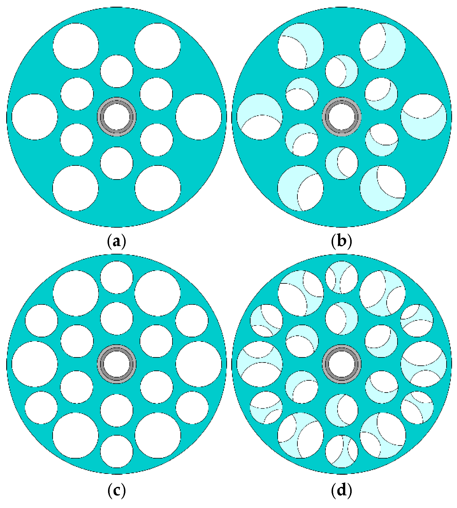
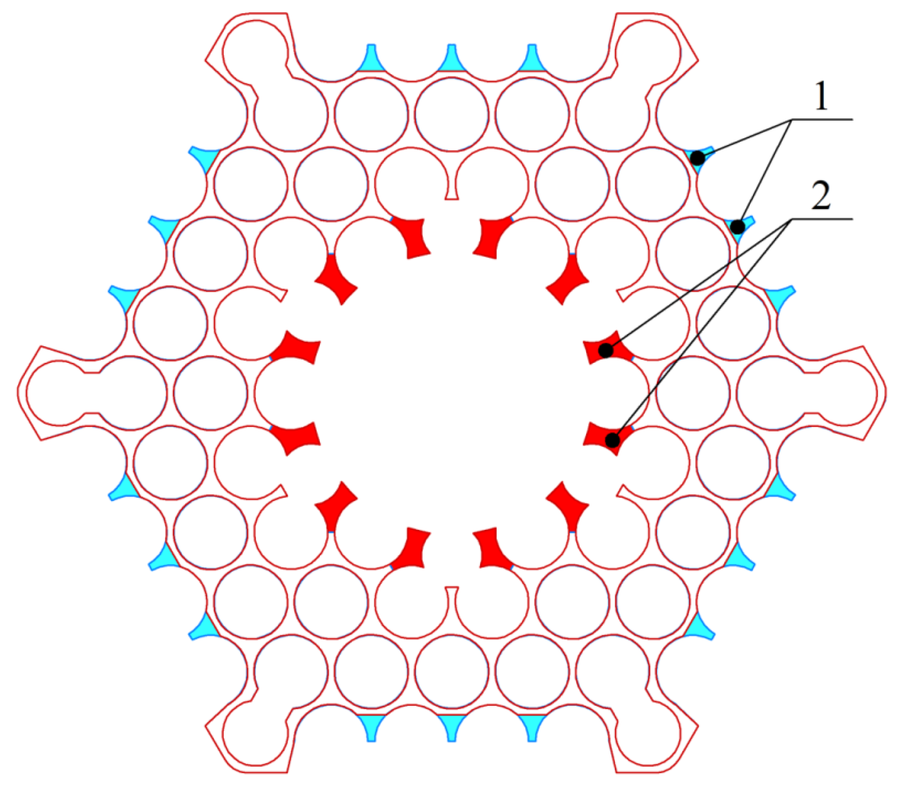
The experiments investigated the effect of two types of orifice inlet devices and integrated grid absorbers on the flow. Each orifice inlet device (Figure 2) comprised two perforated discs mounted on a central sleeve. The loss coefficient of the restrictor was adjusted by rotating one disc relative to the other. The difference between the restrictors lay in the number of flow holes: one type had no additional holes (Figure 2a,b), while the other featured additional holes (Figure 2c,d). The presence of additional holes alters the restrictor’s flow area, consequently changing the controllable range of its loss coefficient. Selecting a restrictor with additional holes was primarily driven by the need to expand the range of resistance adjustment while enabling smooth variation. The integrated grid absorbers (Figure 3) had identical total flow areas but displaced the central and peripheral regions of the fuel rod bundle differently. Figure 4 illustrates their coverage, with color indicating the redistributed areas.
The initial phase of experimental studies focused on determining the loss coefficients of the orifice flow restrictors. Experiments were performed with the restrictors fully open and maximally closed. The maximum disc rotation for each restrictor was 15°, corresponding to the maximum achievable flow area displacement.
The integrated grid absorber possessed an equal flow area and the same loss coefficient. The loss coefficient of each orifice flow device in the open and maximally closed positions was determined with an integrated grid absorber (peripherally displacing type) installed in the test model. The methodology involved measuring the static pressure upstream of the restrictor location under two conditions: with the restrictor installed in the model, and subsequently without it.
Coolant hydrodynamics were studied using pneumometric techniques and a tracer gas injection method.
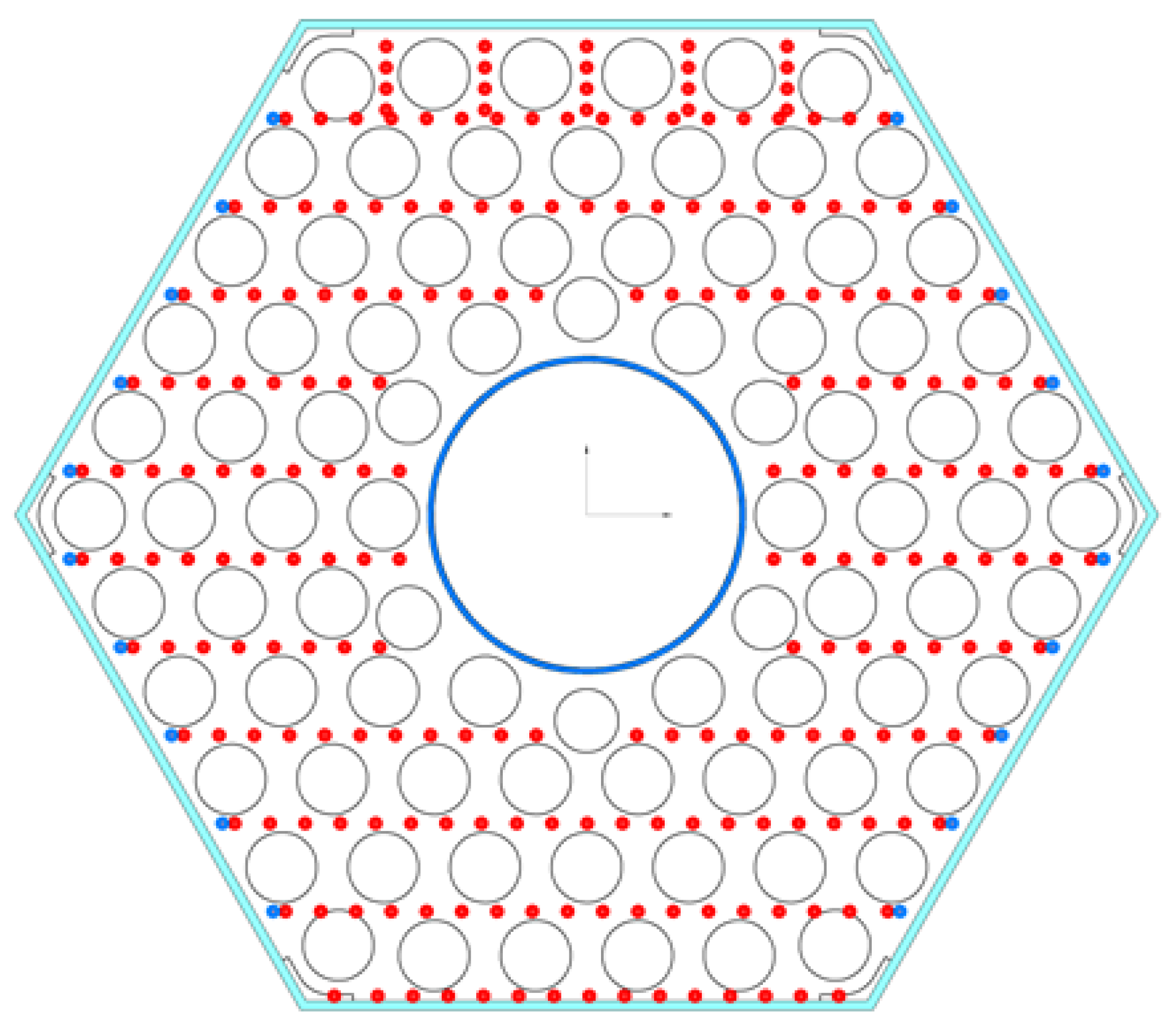
The pneumometric technique used pre-calibrated Pitot tubes and a differential pressure manometer to measure the axial flow velocity at seven cross-sections along the test model. Pitot tubes were inserted into the experimental model through holes in the side surfaces. The measured pressure drop of the flow is up to 2000 Pa. The measurement error of the flow velocity is ±0.05 m/s. These sections were positioned at various axial locations relative to the fuel rod bundle (L/dh = 1.2, 9.6, 24.2, 38.8, 52.6, 70.2, and 87.7, where L is the longitudinal coordinate and dh is the hydraulic diameter of the fuel rod bundle), as depicted in Figure 5. An example of the location of the measuring points is shown in Figure 6.
The tracer gas injection method involved injecting a tracer gas into several cells of the flow passing through the test model. Propane, selected for its similar thermophysical properties to air, served as the tracer gas. The gas was injected via special injection nozzles near the fuel rod attachment region to the diffuser; these nozzles aided in dispersing the injected gas stream. Tracer concentration measurements were taken at a distance downstream from the injection point sufficient to ensure that distortions in the initial propane concentration profile no longer influenced the results. This minimum measurement distance was established based on data from a prior experiment. In that experiment, propane was injected into the center of a fuel rod bundle cell upstream of a grid, and concentration was measured downstream. The injection section was progressively moved away from the grid until the tracer began spreading into adjacent cells. It was ensured that the location of the first tracer concentration measurement section in the fuel assembly inlet test model exceeded this minimum distance obtained during the validation experiment.
The impurity concentration was measured using a Pitot tube. The tube was connected to a gas analyzer via a flexible hose. The Pitot tube was inserted into the experimental model through holes on the side surfaces. An example of the location of measuring points is shown in Figure 6. Tracer concentration was measured using a gas analyzer at various cross-sections downstream of the absorber grid, with a measurement error not exceeding 0.25%.
The locations of the injection cells are shown in Figure 7. Results were visualized as plots of dimensionless axial flow velocity (Wz/Wave) in the measurement sections and tracer concentration (C) distributions.
Dimensionless axial velocity was calculated by normalizing the velocity values measured at each point with the average flow velocity at the system inlet.
The average flow velocity was determined using a calibrated flow meter with known resistance characteristics and Pitot tubes, following the procedure outlined in the Russian State Standard GOST 12.3.018-79 [22]. Depending on the restrictor type and disc position, the average air velocity at the model inlet ranged from 12.0 to 27.8 m/s. The corresponding Reynolds number (Re) range was 31,000 to 71,000. This range corresponds to the self-similar flow regime, which is established for Re values between 25,000 and 30,000. A more detailed justification for the validity of the experimental approach is provided in [10]. Conducting experiments within the self-similarity regime allows the application of the obtained data to analyze the hydrodynamics of the water coolant in a standard fuel assembly.
For clear visualization of the velocity distribution across the cross-section, the data obtained at discrete measurement points were interpolated to construct axial velocity contour plots using specialized software.

3. Results

The experimentally determined loss coefficients for two types of orifice inlet devices in both the fully open and maximally closed positions are presented in Table 1. The loss coefficient control range of the orifice inlet device without additional holes exceeds that of the device with additional holes by a factor of 18. However, the orifice inlet device with additional holes provides a loss coefficient value 6.4 units lower in the fully open position compared to the orifice inlet device without additional holes in its open position. This difference could be significant for nuclear core hydraulic profiling.
The generalized experimental results, which include quantitative measurements of the loss coefficient, are shown in Table 1.

3.1. Dynamic Pressure Probe Measurements

3.1.1. Integrated Grid Absorber with Peripheral Flow Restriction

Studies of coolant hydrodynamics using the pneumometric method in the fuel assembly model with an integrated grid absorber covering the peripheral area revealed the following flow features.
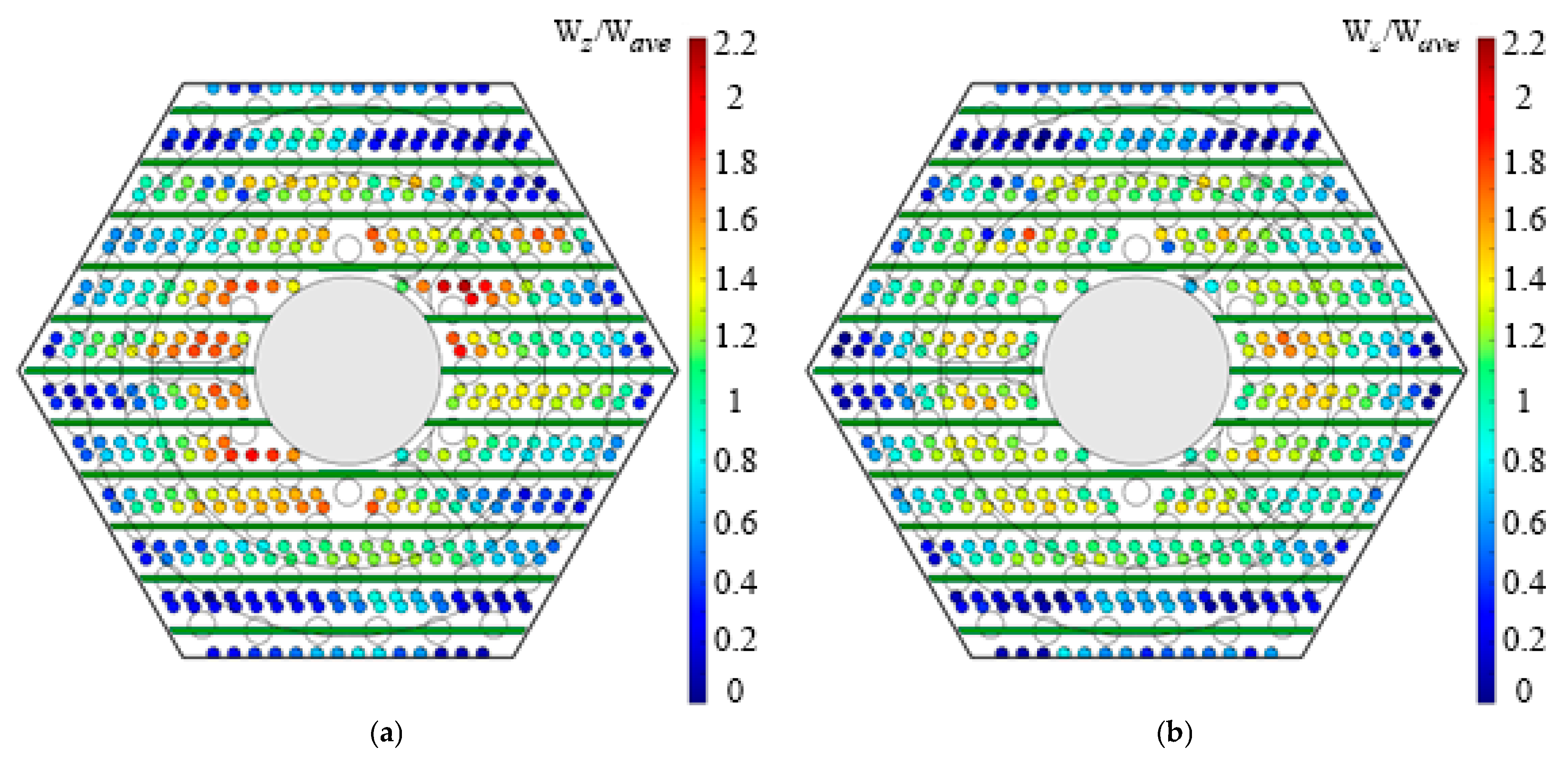
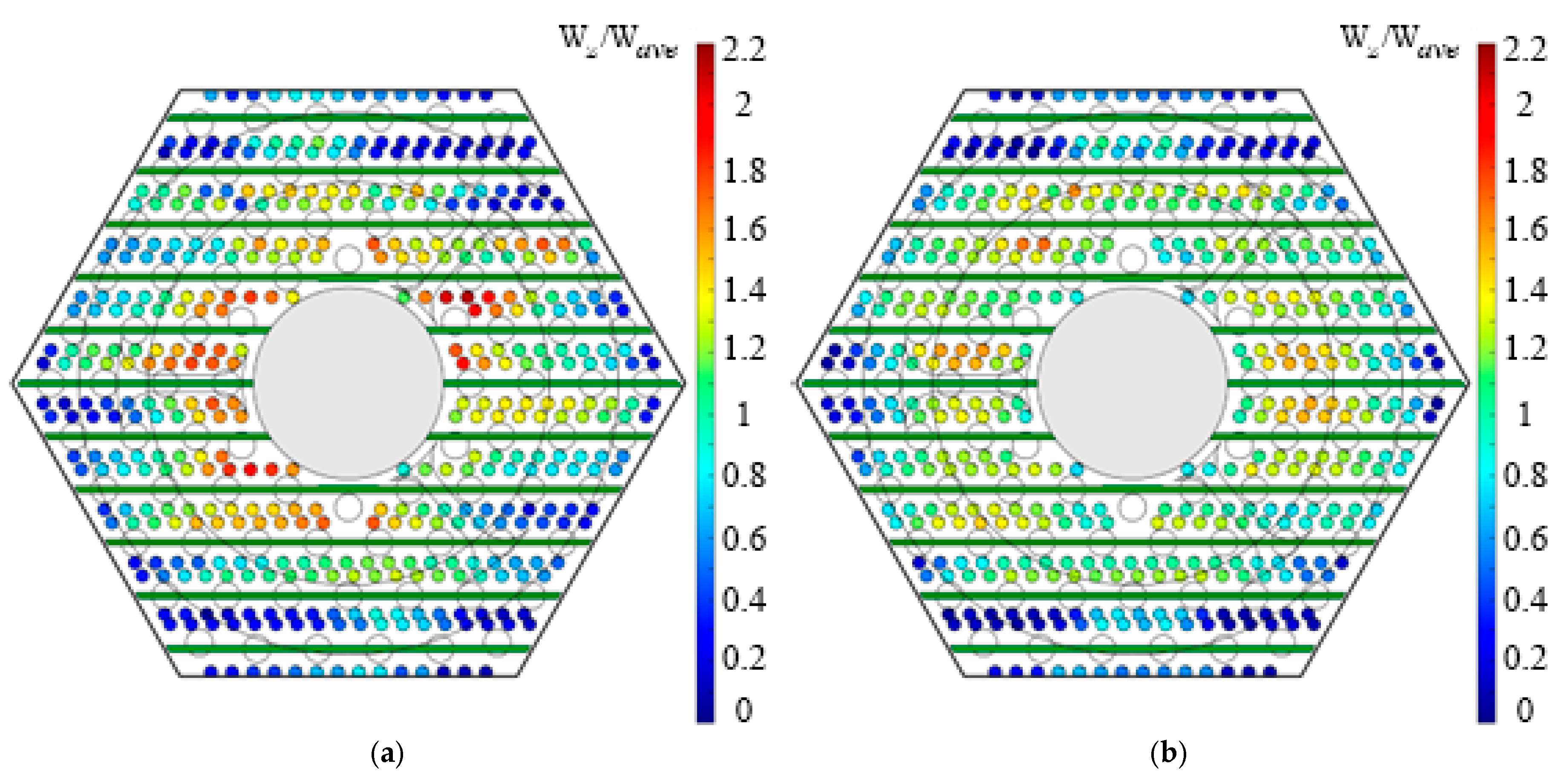
  • In the fuel rod attachment area to the diffuser (L/dh = 1.2), with both types of orifice inlet devices installed in the open position, the axial flow velocity distributions exhibit a similar pattern (Figure 8). The minimum dimensionless axial flow velocity was localized near the model wrapper (within two rows of fuel rods near the wrapper faces parallel to the fuel rod attachment plates and within one row near the other wrapper faces) and amounted to 0.05–0.60 in the region of the stiffness corners and 0.3–0.8 at the centers of the wrapper faces. This location of the low-velocity region is likely caused by the combined influence of the structural elements within the inlet section from the orifice inlet device to the integrated grid absorber. The expansion of the low-velocity area near the wrapper faces parallel to the attachment plates could arise from the configuration of the attachment plates themselves and the diffuser, which restrict the flow area such that coolant cross-flow into the peripheral cells is practically absent. In the region of the stiffness corners, the axial velocity may be additionally affected by flow deceleration upstream of the integrated grid absorber, which significantly restricts the flow area in the corner region. The region of high axial flow velocity was located in the central part of the cross-section, where the dimensionless velocity ranged from 1.4 to 1.8. Its localization can be attributed to the formation of high-velocity jets downstream of the orifice inlet device holes. Closing the orifice inlet device with additional holes did not lead to a significant change in the axial velocity distribution; only near the centers of the wrapper faces did the velocity increase from 0.3–0.8 to 0.7–1.0 (Figure 9).
When the orifice inlet device without additional holes was installed in the maximally closed position, the velocity distribution pattern underwent significant changes (Figure 9a). The boundaries of the low- and high-velocity regions expanded. Locally, in the region of the central displacer, the axial velocity value exceeded the average flow velocity by a factor of 2.2. This could have been caused by the intensification of jets with high axial velocity formed downstream of the orifice inlet device holes due to their partial closure.
2.
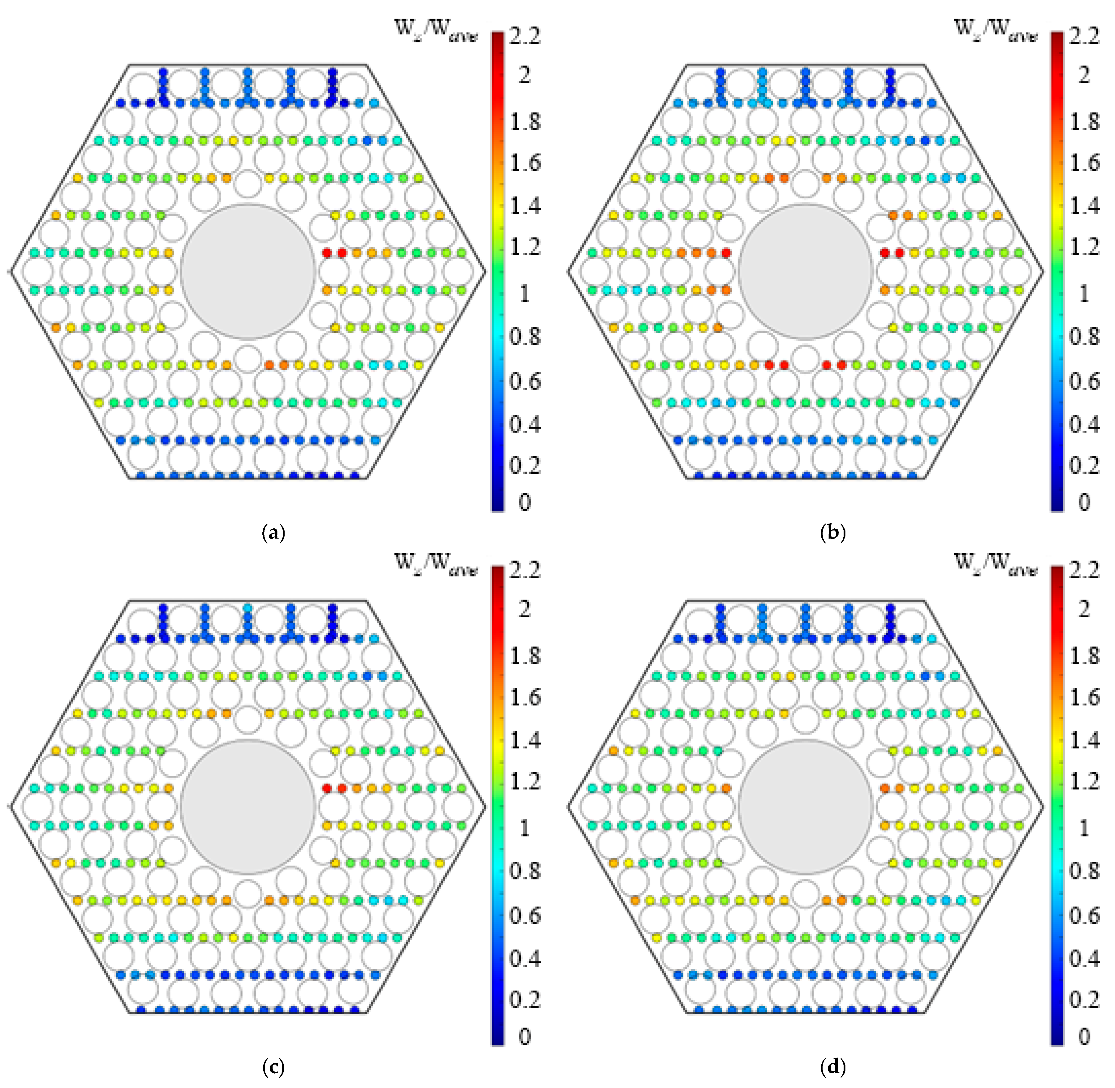
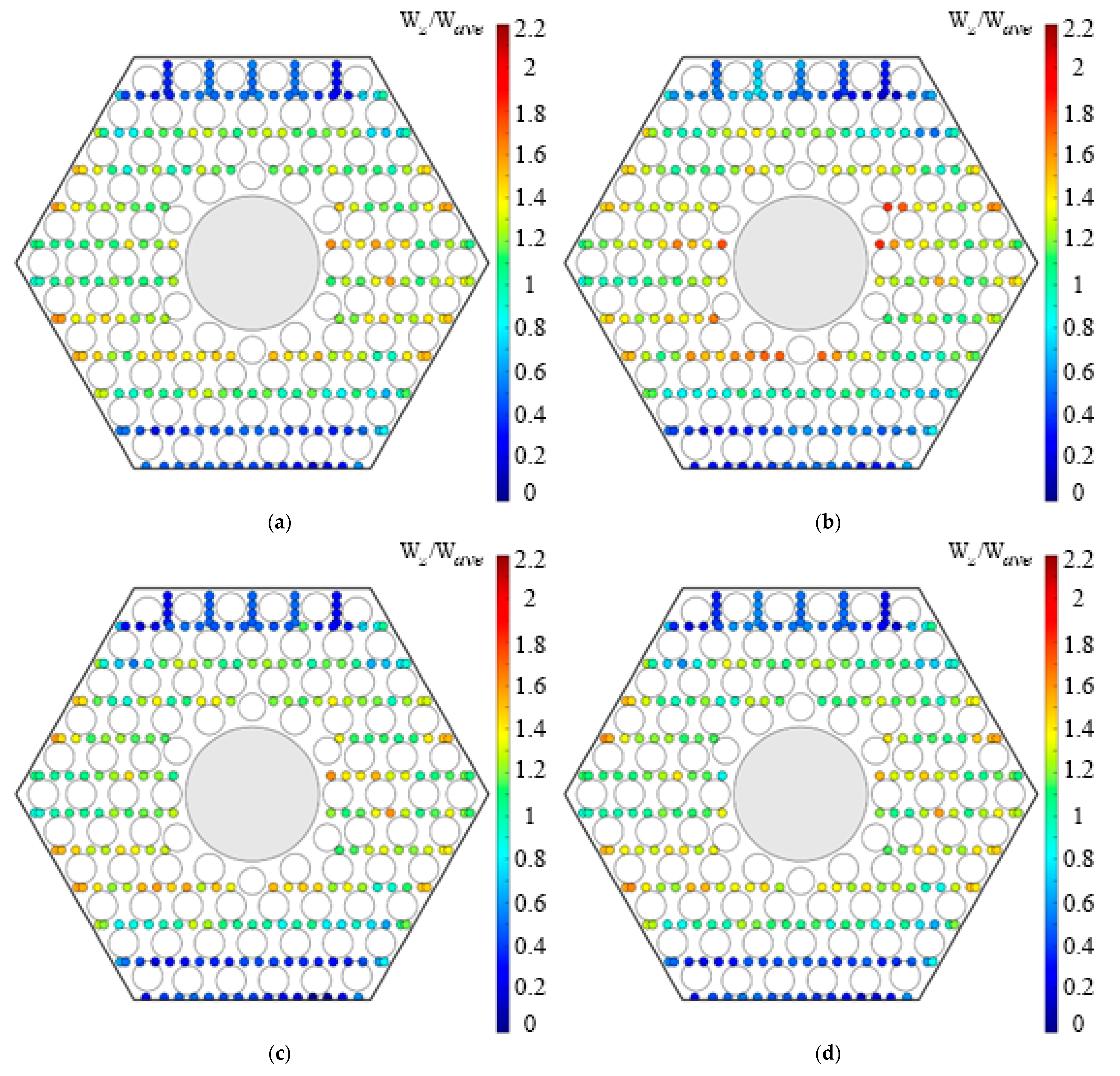
Downstream of the integrated grid absorber (L/dh = 9.6) displacing the peripheral region, with both types of orifice inlet devices installed in the open position, the preservation of the low axial velocity region near the wrapper faces parallel to the fuel rod attachment plates is characteristic, where the velocity was 0.1–0.6 (Figure 10a,c). When the flow area of the orifice inlet device without additional holes was closed, a local increase in the dimensionless axial flow velocity in the central part of the cross-section was observed (Figure 10b). Asymmetry in the axial velocity distributions is observed regardless of the type of installed orifice inlet device or the degree of its closure, which could be due to the persistent influence of the configuration of the fuel rod attachment plates to the diffuser, preventing cross-flow in the direction perpendicular to these plates.
3.
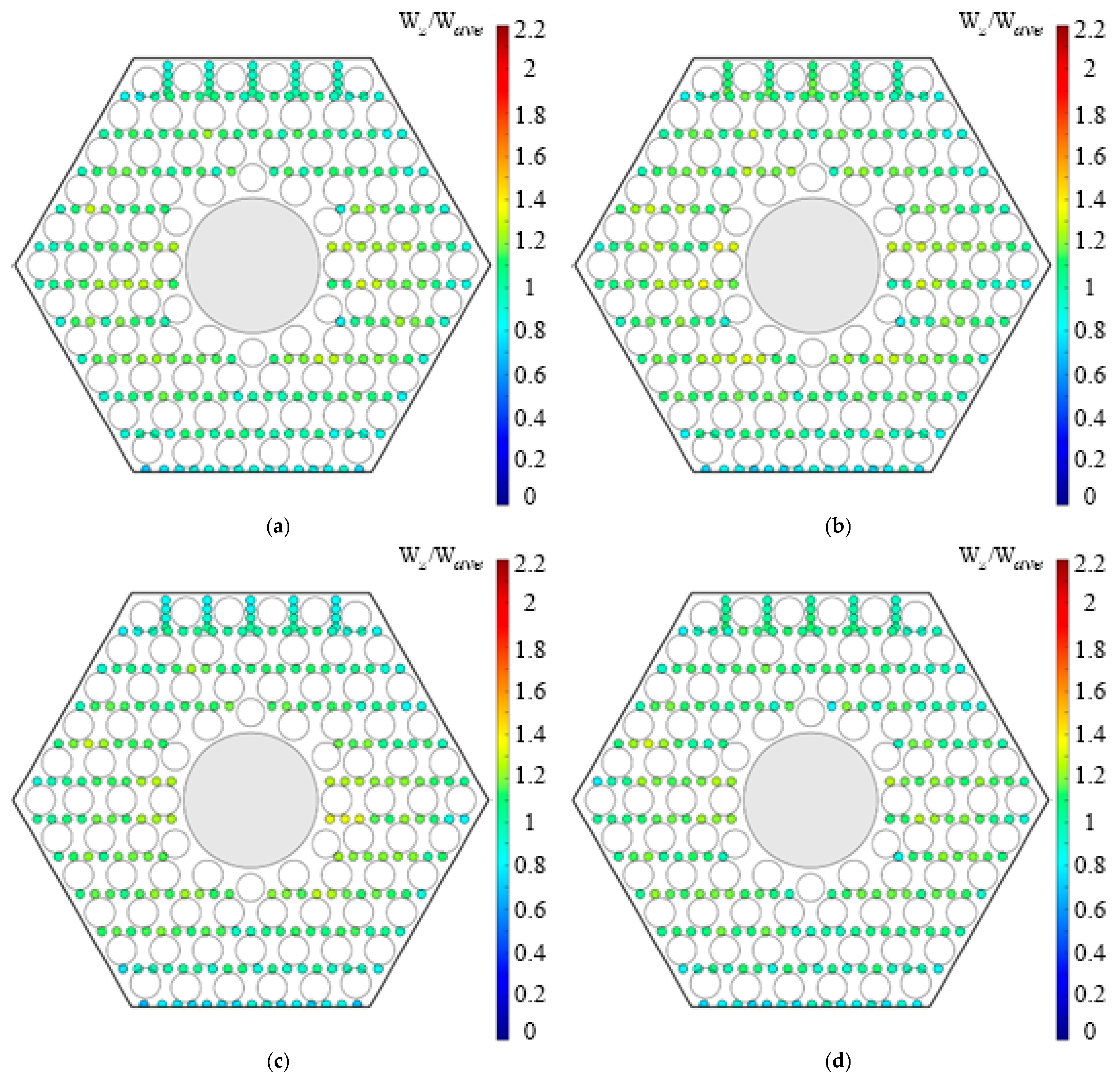
With increasing distance downstream of the integrated grid absorber into the depth of the fuel rod bundle, a gradual equalization of the axial flow velocity across the cross-section occurred. The influence of the inlet section structural elements was practically absent in the cross-section located at the mid-span of the fuel rod bundle between the first and second spacer grids (L/dh = 70.2). This is characteristic for the case of installing the orifice inlet device with additional holes in the assembly, regardless of the degree of its flow area closure, as well as for installing the orifice inlet device without additional holes with a fully open flow area (Figure 11a,c,d). For these configurations, regions of low axial flow velocity (0.5–0.8) are observed adjacent to the surfaces of the hexagonal wrapper and the central displacer, which could have occurred due to flow deceleration near these surfaces. When the flow area of the orifice inlet device without additional holes was closed, equalization of the dimensionless axial flow velocity occurred only upstream of the second spacer grid (L/dh = 87.7) (Figure 11b).

3.1.2. Integrated Grid Absorber with Central Flow Restriction

Experimental studies of coolant hydrodynamics using the pneumometric method in a model equipped with an integrated grid absorber featuring central flow restriction yielded the following results.
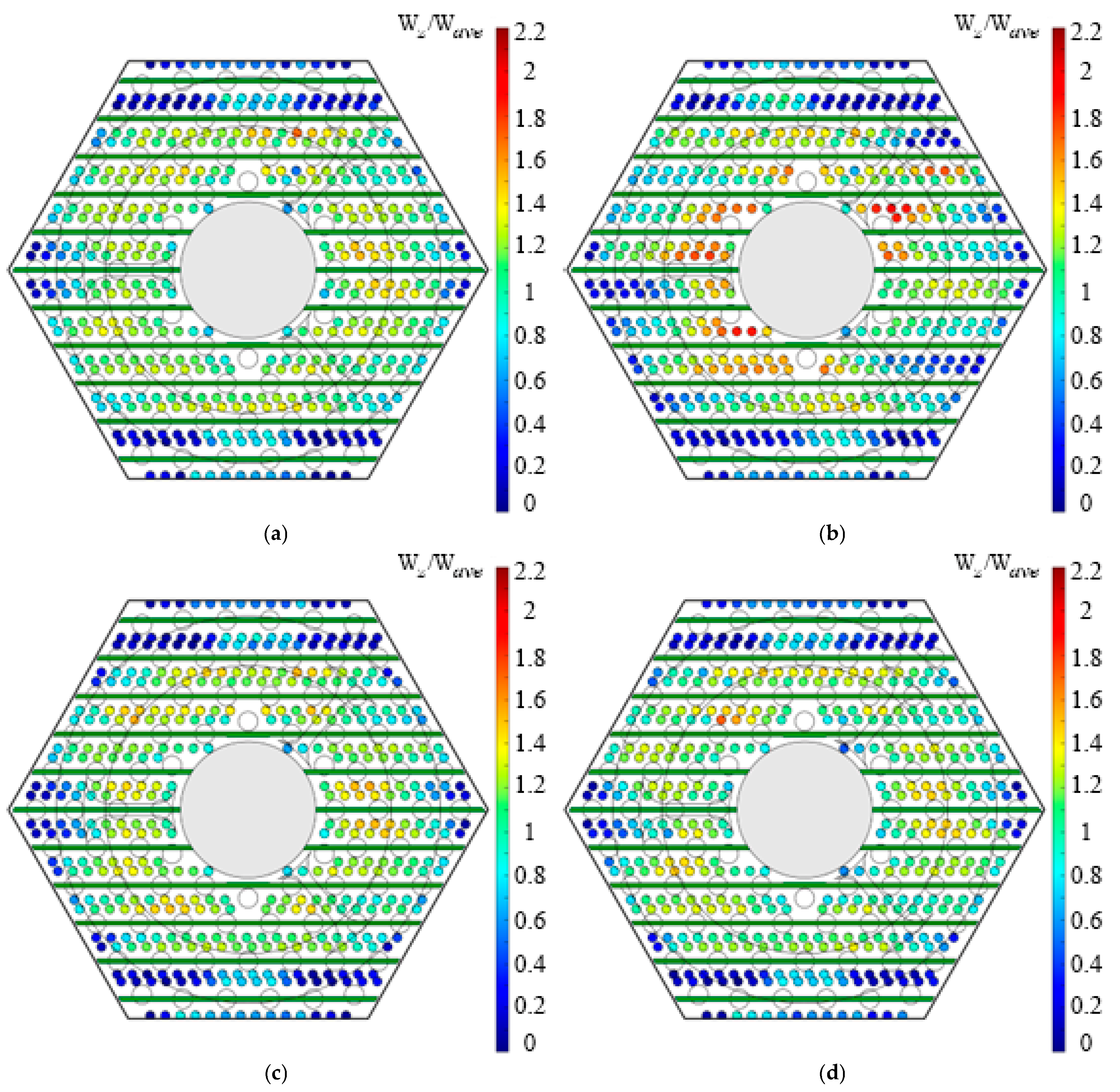
  • At the cross-section located at the fuel rod attachment point to the diffuser (L/dh = 1.2), with the orifice inlet device without additional holes in the open position and with the orifice inlet device with additional holes regardless of its flow area reduction, the location of the low axial velocity region changed. This region became localized near the corner ribs, as the dimensionless axial velocity along the face centers increased from 0.05–0.60 to 0.50–1.00 (Figure 12). When the orifice inlet device without additional holes was installed in the model in the fully restricted position, no changes in the axial velocity distribution were observed.
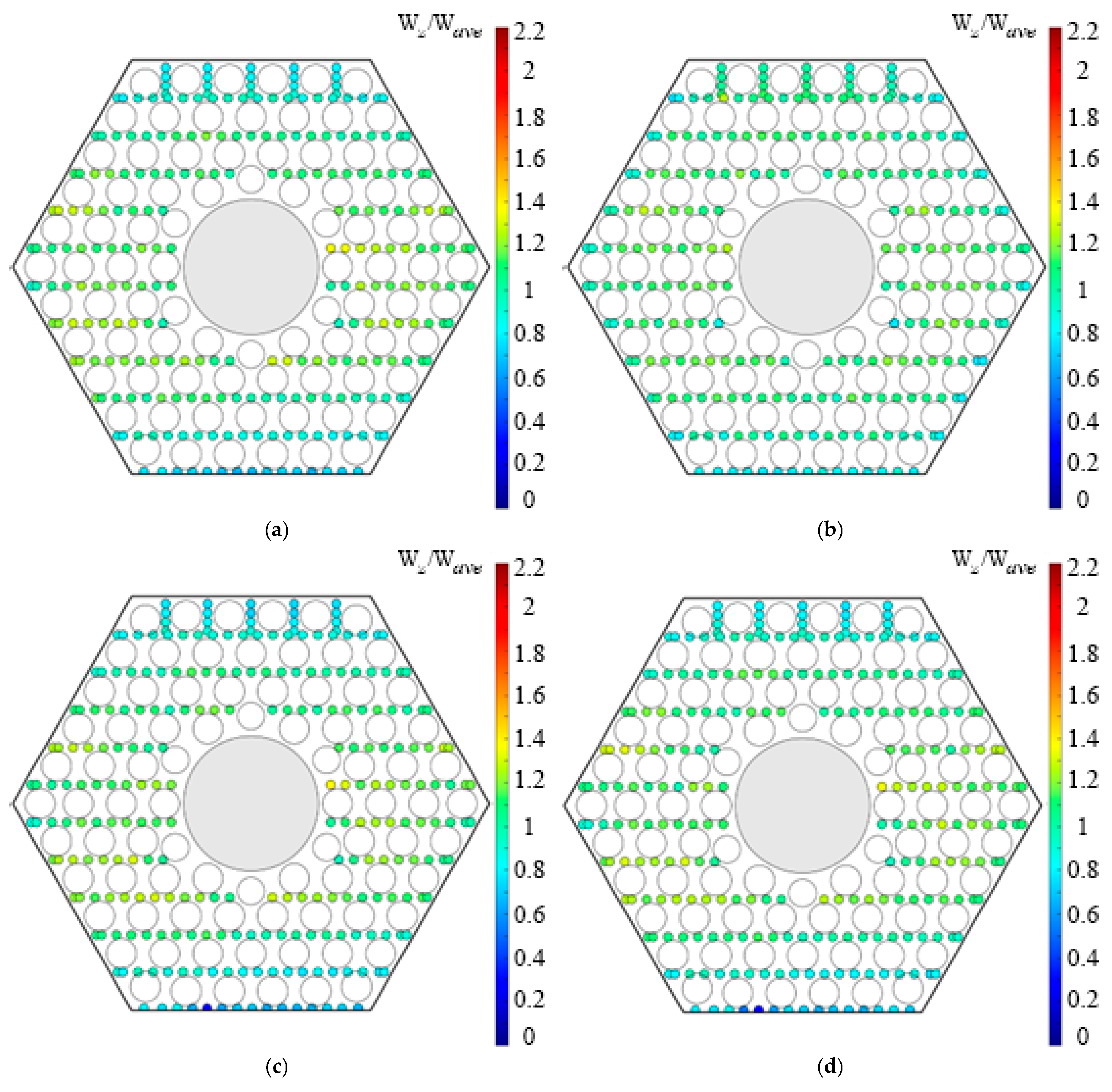
  • Downstream of the integrated grid absorber with central flow restriction (L/dh = 9.6), regardless of the type of installed orifice inlet device or its restriction level, an increase in axial flow velocity was observed at the periphery of the fuel rod bundle, except in the region of the reinforcing corner ribs where it reached 17% (Figure 13). In the region of the central displacer, local maxima of axial velocity showed a decrease in flow velocity magnitude compared to this parameter when a model with an integrated grid absorber featuring peripheral flow restriction was installed. When orifice inlet devices with an open flow area were installed, the maximum axial velocity decreased by 20%, and when the flow area of the orifice inlet devices was restricted, it decreased by 10%. The asymmetry in axial velocity distributions persisted, which the installation of an integrated grid absorber of a different design had practically no influence on.
  • The design of the fuel assembly inlet section had practically no effect on the axial velocity distribution by the cross-section located midway between the spacer grids (L/dh = 70.2) in the case of installing the orifice inlet device without additional holes with a restricted flow area (Figure 14). In all other cases, the influence of the elements (orifice inlet device, diffuser, and integrated grid absorber) diminished upstream of the first spacer grid (L/dh = 38.8).
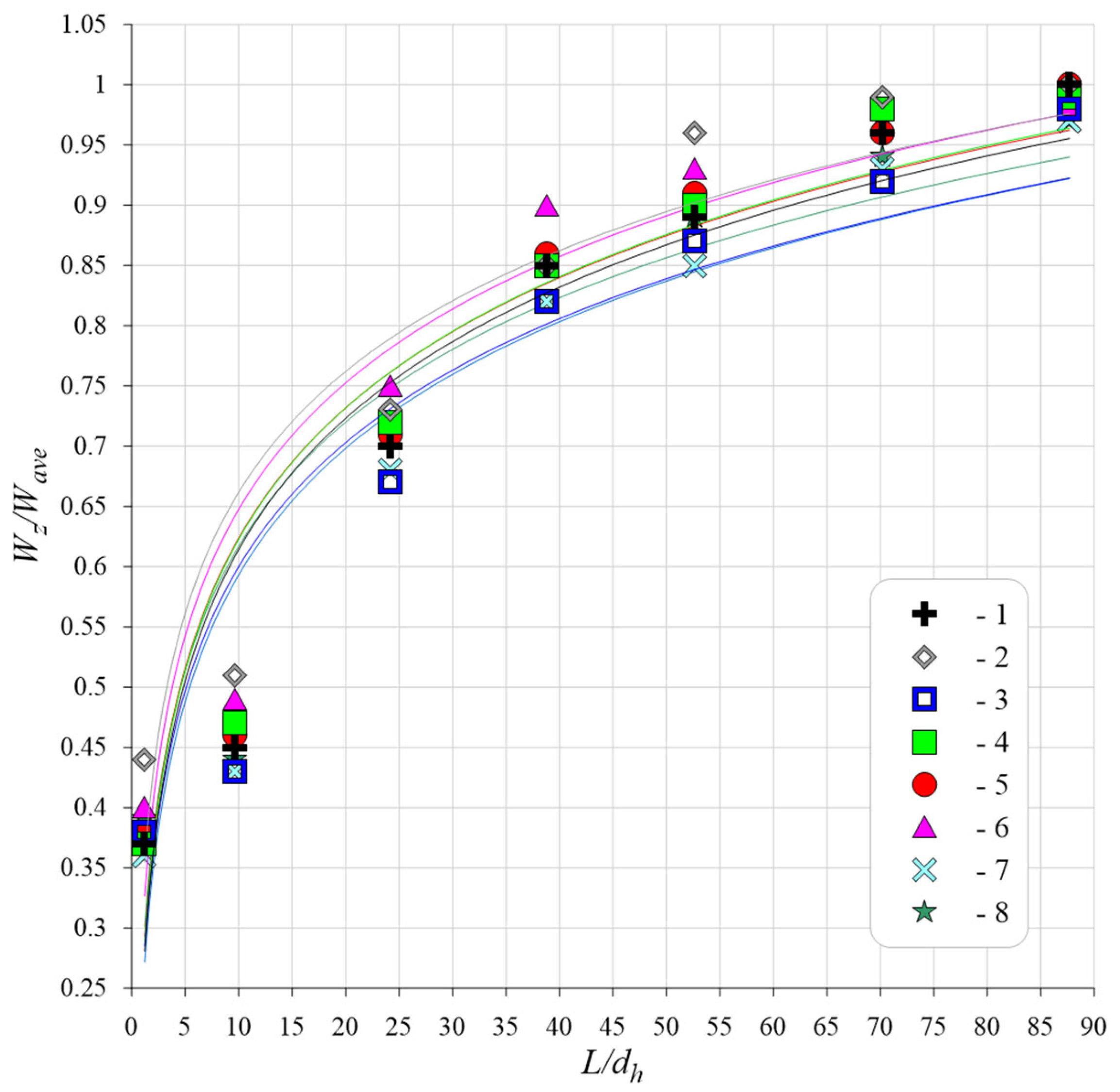
  • The axial velocity at the entrance to the fuel element bundle near the sides of the cover is low (0.36–0.43) when the dimensionless parameter L/dh is 1.2. In front of the first spacer grid, the velocity increases by a factor of 2 to (0.81–0.89) at L/dh = 52.6. Complete alignment with the average outgoing velocity occurs before the second spacer grid at L/dh = 87.7 (Figure 15). Changing the design of the absorbing grid did not affect the process of equalization of the axial velocity in this area.
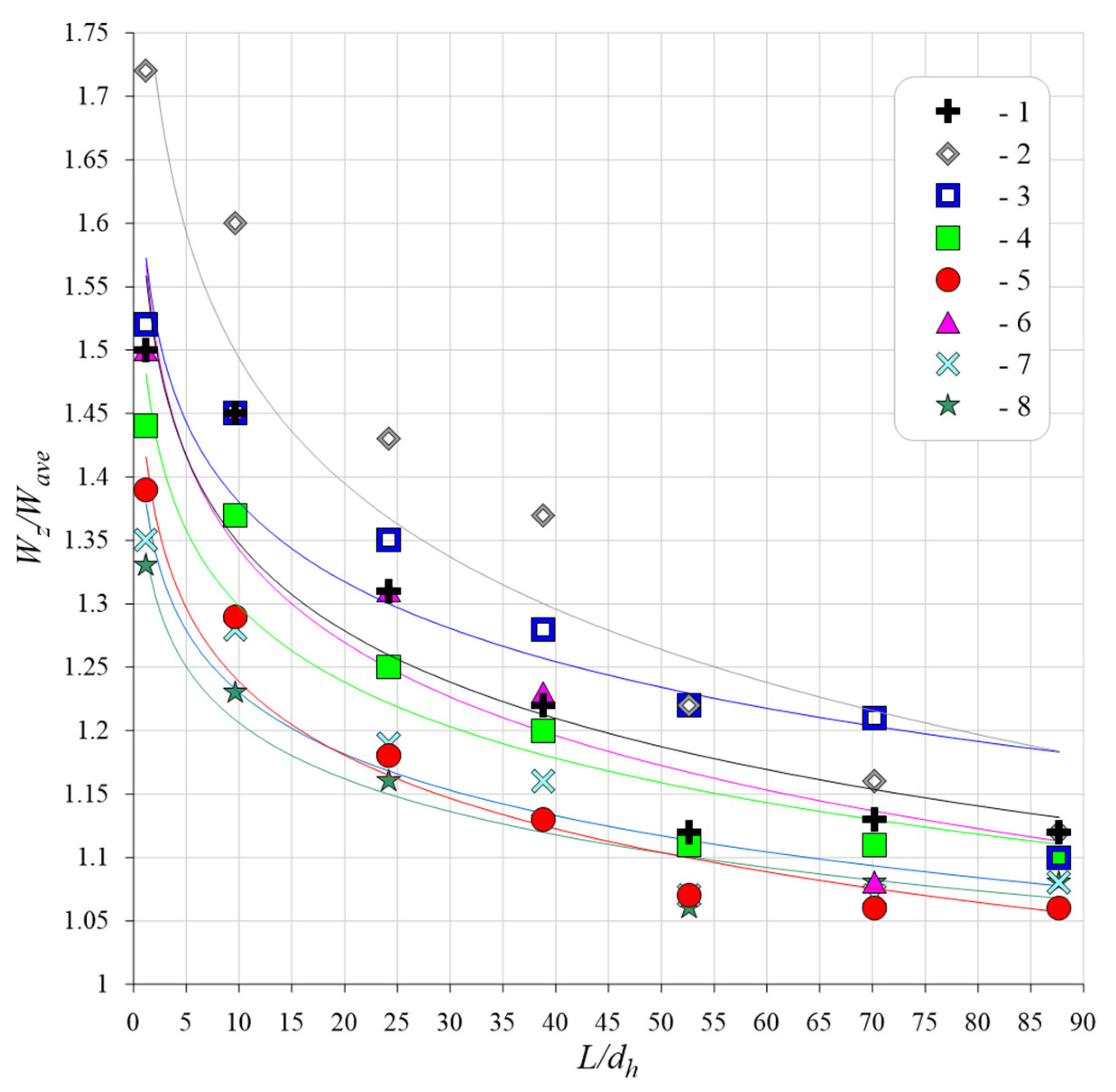
  • Near the central tube, the axial velocity at L/dh = 1.2 was (1.33–1.72) at the entrance to the fuel bundle. Before the second spacer grid, the axial velocity did not equalize with the average outlet velocity and was (1.06–1.12) at L/dh of 87.7. A change in the absorbing grid design reduced the axial velocity near the center by 15% (Figure 16).
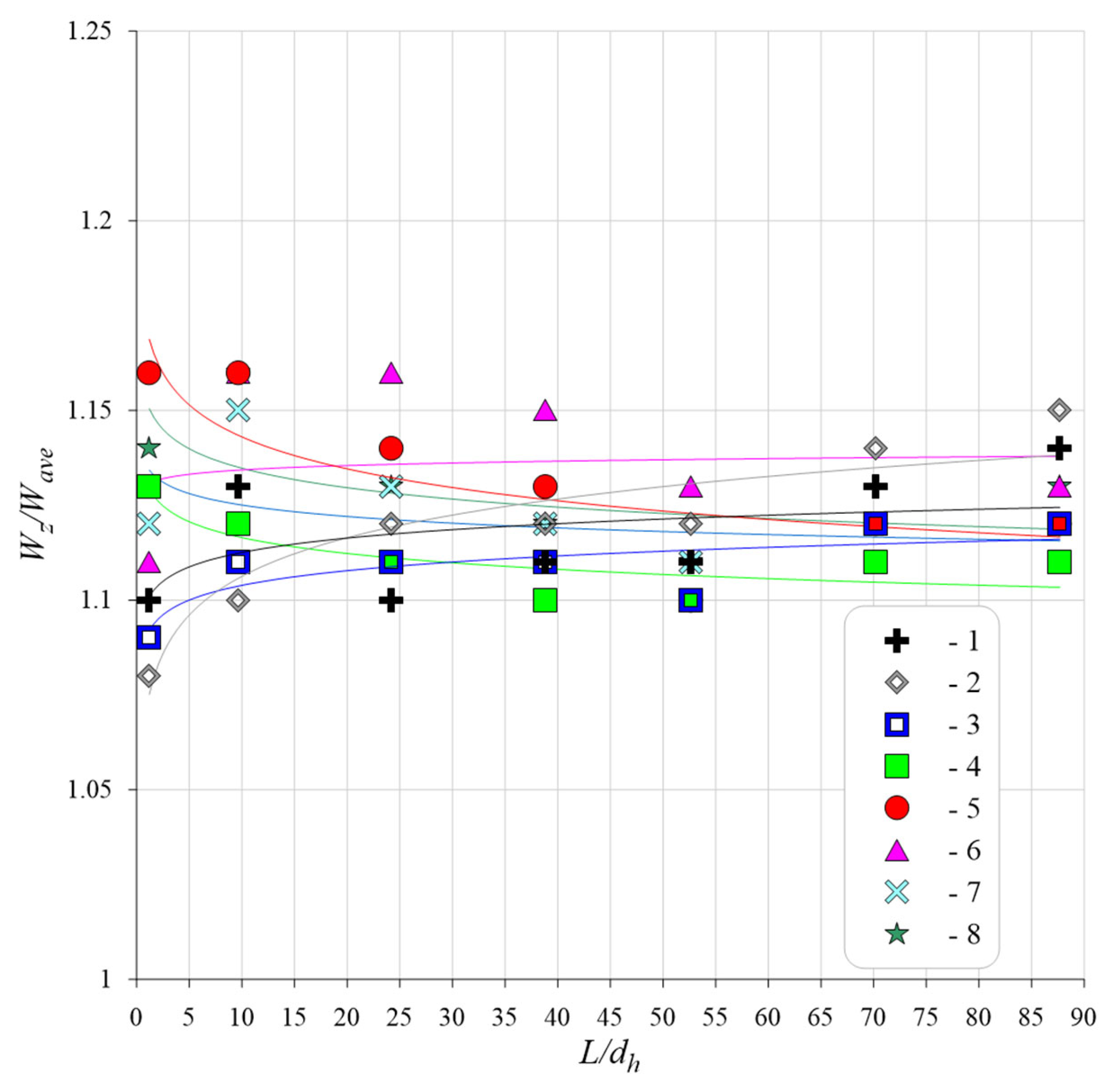
  • The axial velocity in the regular cells at the entrance to the fuel element beam (L/dh = 1.2) was between 1.07 and 1.16. In front of the second spacer grating (L/dh = 87.7), the axial velocity ranged from 1.11 to 1.15. The change in the design of the absorbing grating did not have a significant effect on the value of the axial flow velocity in regular cells (see Figure 17).

3.2. Tracer Injection Technique

In experimental studies on a model equipped with an integrated grid absorber featuring central flow restriction, conducted using the contrast agent injection method, the following results were obtained.
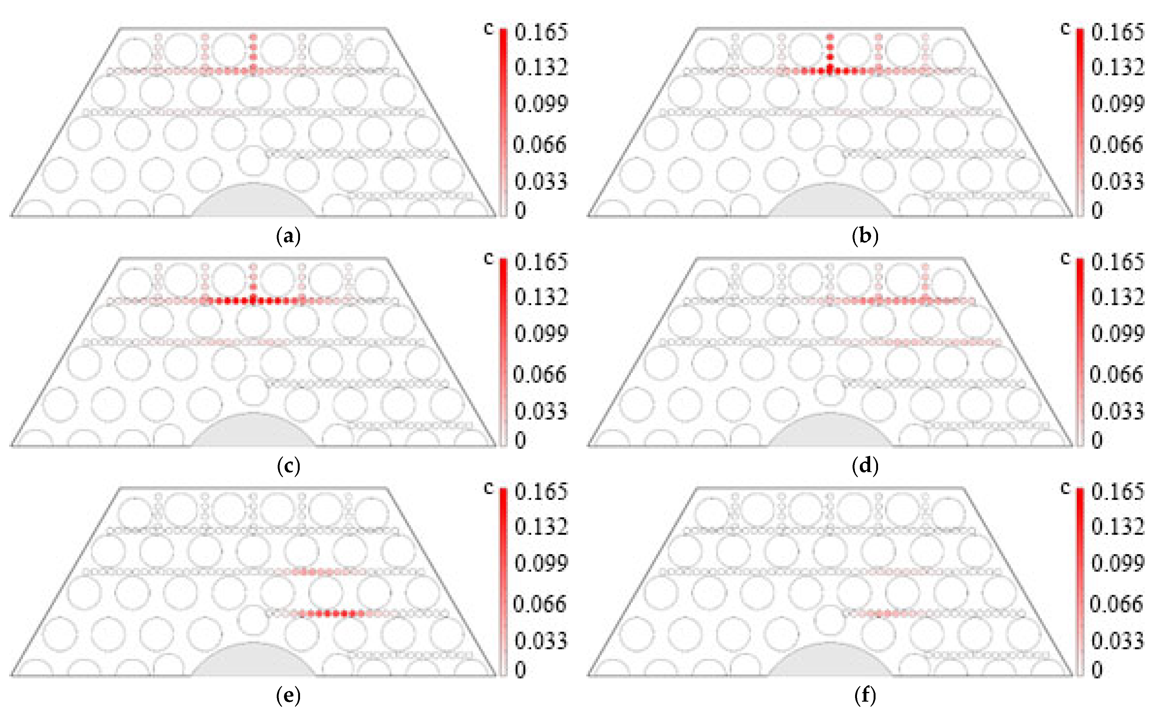
Downstream of the integrated grid absorber with central flow restriction (L/dh = 9.6), regardless of the type of installed orifice inlet device, the maximum agent concentration C = 0.165 was localized in the injection region, spreading horizontally in both directions from it, with slight leakage of the agent into adjacent horizontal rows of cells (Figure 18). The value of the dimensionless impurity concentration in these cells was (0.01–0.06). This was caused by the low intensity of coolant flow mixing. This is due to the presence of fuel element mounting plates in the fuel assembly design. These structural elements prevent the flow from moving in a direction perpendicular to the plates.
The process of lateral flow redistribution when installing the orifice inlet device with additional holes in the open position occurred more intensively compared to the orifice inlet device without additional holes. Equalization of the relative concentration across the cross-section to 0.04, regardless of the contrast agent injection region, occurred at the section located upstream of the first spacer grid (L/dh = 38.8) when the orifice inlet device with additional holes was installed in the open position. Conversely, with the orifice inlet device without additional holes and agent injection into cells of the first and second rows of fuel rods from the face of the hexagonal wrapper parallel to the plates securing the fuel rods to the diffuser, equalization was observed downstream of the first spacer grid (L/dh = 52.6). When injecting the agent into the cell of the third row of fuel rods, concentration equalization occurred upstream of the second spacer grid (L/dh = 87.7).
Restriction of the orifice inlet device flow area had no influence on the intensity of the lateral flow redistribution process. This was characteristic for all injection zones.
Thus, the plates that attach fuel rods to the diffuser have a significant impact on the intensity and direction of transverse flows. This impact extends up to the second grid spacing (L/dh = 87.7).

4. Conclusions

  • Regardless of the type or position of the installed orifice inlet device, the use of an integrated grid absorber featuring central flow restriction intensifies the process of axial flow velocity equalization across the fuel rod bundle cross-section compared to using an integrated grid absorber featuring peripheral flow restriction. When the orifice inlet device without additional holes is installed in the restricted position, the influence of the inlet section design diminishes at a distance 17.5 L/dh earlier. In all other cases of orifice inlet device installation, this influence diminishes 31.4 L/dh earlier compared to the case with the integrated grid absorber featuring peripheral flow restriction.
  • The orifice inlet device without additional holes offers a wider range for regulating its loss coefficient (8.9–49.9). However, the orifice inlet device with additional holes in the open position provides a loss coefficient (2.5) lower than that of the device without additional holes.
  • When designing new reactor cores, the combined use of both device designs is recommended. Combined use of orifice inlet devices implies installing devices with additional holes in the highest-power fuel assemblies (FAs), and devices without additional holes in the remaining assemblies.
  • The use of an integrated grid absorber featuring central flow restriction will accelerate the process of axial flow velocity equalization across the fuel rod bundle cross-section.
  • The obtained experimental data can be used not only to optimize the hydraulic profiling scheme for new small-sized nuclear plant cores and substantiate their safety but also as an empirical database for validating the CFD codes.

Author Contributions

Data curation, A.R.; Formal analysis, A.R. and A.D.; Funding acquisition, D.S.; Investigation, A.R., D.K. and D.N.; Methodology, D.D. and A.P.; Project administration, A.R.; Software, A.R. and A.D.; Supervision, S.D.; Visualization, A.P. and T.D.; Writing—original draft, A.R. and D.D.; Writing—review & editing, A.R. All authors have read and agreed to the published version of the manuscript.

Funding

This research was funded by the Ministry of Science and Higher Education of the Russian Federation (project No. FSWE-2024-0003).

Institutional Review Board Statement

Not applicable.

Informed Consent Statement

Not applicable.

Data Availability Statement

The original contributions presented in the study are included in the article, and further inquiries can be directed to the corresponding author.

Conflicts of Interest

The authors declare no conflicts of interest.

Abbreviations

The following abbreviations are used in this manuscript:
CFDComputational Fluid Dynamics
FAFuel Assemblies
NNSTUNizhniy Novgorod State Technical University
SMRSmall Modular Reactor

References

  1. Samoylov, O.B.; Romanov, A.I.; Galitskikh, V.Y.; Zakharychev, A.A.; Morozov, O.A.; Mitrofanov, A.V.; Silaev, V.Y. Analysis of the Operating Experience of the Cores of First-Generation Nuclear Icebreakers. Database to Substantiate and Develop New Nuclear Icebreakers and Floating Power Units. Tekhnologii Obespecheniya Zhiznennogo Tsikla Yad. Energeticheskikh Ustanov. [Technol. Ensuring Life Cycle Nucl. Power Plants] 2023, 3, 16–24. (In Russian) [Google Scholar]
  2. Zverev, D.L.; Samoilov, O.B.; Morozov, O.A.; Zakharychev, A.A.; Silaev, V.Y.; Matyash, P.B.; Vishnev, A.Y.; Kashka, M.M.; Darbinyan, O.E. Cores of Operating Nuclear Icebreakers. Sudostroenie [Shipbuilding] 2020, 1, 13–16. (In Russian) [Google Scholar]
  3. Petrunin, V.V.; Sheshina, N.V.; Fateev, S.A.; Kurachenkov, A.V.; Shchekin, D.V.; Brykalov, S.M.; Bezrukov, A.A. Scientific and Technical Aspects of Creating the Innovative RITM-200N Reactor Unit for a Small Nuclear Power Plant. At. Energy 2023, 134, 1–10. [Google Scholar] [CrossRef]
  4. Romanov, A.I. Development of Cores for SMRs and FPUs. Current Status and Development Directions. Bull. At. Sci. Technol. Mater. Sci. New Mater. [Vestnik atomnoi nauki I techniki Seria Materialovedenie I Novie Materiali] 2023, 5, 86–111. (In Russian) [Google Scholar]
  5. Liu, Y.; Wang, C.; Tian, W.; Su, G.; Qiu, S. Experimental study of cross flow and lateral pressure drop in a 5 × 5 rod bundle with mixing vane spacer grid. Nucl. Eng. Des. 2019, 351, 9–19. [Google Scholar] [CrossRef]
  6. Liu, Y.; Li, Y.; Wang, C.; Tian, W.; Su, G.; Qiu, S. Investigation on cross-flow characteristics of two different mixing vane grid in a 5 × 5 rod bundle. Ann. Nucl. Energy 2024, 202, 110934. [Google Scholar] [CrossRef]
  7. Wang, C.; Tian, W.; Zhang, D.; Su, G.; Qiu, S. Experimental investigation of the turbulent flow in a rod bundle channel with spacer grids. Ann. Nucl. Energy 2019, 128, 295–306. [Google Scholar] [CrossRef]
  8. Caraghiaur, D.; Anglart, H. Experimental investigation of turbulent flow through spacer grids in fuel rod bundles. Nucl. Eng. Des. 2009, 239, 2013–2021. [Google Scholar] [CrossRef]
  9. Matyukhin, N.M.; Ushakov, P.A.; Yudina, E.V. Experimental study of the effect of spacer grid on the flow structure in fuel assemblies of the AES 2006 reactor. Therm. Eng. 2012, 59, 518–525. [Google Scholar] [CrossRef]
  10. Dmitriev, S.; Demkina, T.; Dobrov, A.; Doronkov, D.; Kuritsin, D.; Nikolaev, D.; Pronin, A.; Riazanov, A.; Solntsev, D. Modeling and Visualization of Coolant Flow in a Fuel Rod Bundle of a Small Modular Reactor. Fluids 2024, 9, 235. [Google Scholar] [CrossRef]
  11. Dmitriev, S.M.; Demkina, T.D.; Dobrov, A.A.; Doronkov, D.V.; Doronkova, D.S.; Pronin, A.N.; Ryazanov, A.V. Coolant Hydrodynamics at the Inlet to the Reactor Core of a RITM-Type Reactor at a Small Nuclear Power Plant. Therm. Eng. 2024, 71, 375–390. [Google Scholar] [CrossRef]
  12. Dmitriev, S.M.; Ivanov, A.S.; Simonenko, V.A.; Frolov, D.V.; Nikiforov, M.V.; Pasyukov, S.D.; Kotlovanov, I.P.; Sharapov, I.K.; Yurkov, S.I.; Dolgorukova, A.G. Study of Coolant Flow Characteristics at the Inlet to the Reactor Core of the RITM Icebreaker Reactor. At. Energy 2024, 136, 113–117. [Google Scholar] [CrossRef]
  13. Dragunov, Y.G.; Solonin, V.I.; Perevezentsev, V.V.; Petrov, I.V. Vibrations of fuel-element bundles in VVER fuel assemblies excited by turbulent coolant flow. At. Energy 2013, 113, 153–162. [Google Scholar] [CrossRef]
  14. Dragunov, Y.G.; Solonin, V.I.; Perevezentsev, V.V.; Petrov, I.V. Experimental studies of the dynamical characteristics of fuel-element bundles of VVER fuel assemblies in turbulent coolant flow. At. Energy 2013, 113, 295–299. [Google Scholar] [CrossRef]
  15. Solonin, V.I.; Perevezentsev, V.V. Studying the vibration and random hydrodynamic loads on the fuel rods bundles in the fuel assemblies of the reactor installations used at nuclear power stations equipped with VVER reactors. Therm. Eng. 2012, 59, 384–389. [Google Scholar] [CrossRef]
  16. Dmitriev, S.M.; Demkina, T.D.; Dobrov, A.A.; Doronkov, D.V.; Pronin, A.N.; Ryazanov, A.V. A study of the coolant flow at the inlet to the fuel assembly of the RITM nuclear icebreaker reactor. At. Energy 2024, 136, 141–145. [Google Scholar] [CrossRef]
  17. Dmitriev, S.M.; Demkina, T.D.; Dobrov, A.A.; Doronkov, D.V.; Doronkova, D.S.; Legchanov, M.A.; Pronin, A.N.; Ryazanov, A.V.; Solntsev, D.N. Features of forming a coolant flow in the inlet section of the fuel cartridge for a RITM small nuclear power plant. Thermophys. Aeromech. 2024, 31, 631–644. [Google Scholar] [CrossRef]
  18. Dmitriev, S.M.; Barinov, A.A.; Varentsov, A.V.; Doronkov, D.V.; Solntsev, D.N.; Khrobostov, A.E. Experimental studies of local coolant hydrodynamics using a scaled model of cassette-type fuel assembly of a KLT-40S reactor. Therm. Eng. 2016, 63, 567–574. [Google Scholar] [CrossRef]
  19. Dmitriev, S.M.; Demkina, T.D.; Dobrov, A.A.; Doronkov, D.V.; Doronkova, D.S.; Pronin, A.N.; Ryazanov, A.V.; Solntsev, D.N.; Khrobostov, A.E. Hydrodynamics of a Coolant in the Outlet Section of a Cassette Type Fuel Assembly. J. Eng. Phys. Thermophys. 2024, 97, 195–203. [Google Scholar] [CrossRef]
  20. Dmitriev, S.M.; Demkina, T.D.; Dobrov, A.A.; Doronkov, D.V.; Doronkova, D.S.; Kuritsin, D.D.; Pronin, A.N.; Ryazanov, A.V. Experimental Determination of the Hydrodynamic Characteristics of the Coolant Flow at the Outlet from the Reactor Core of the RITM Icebreaker Reactor. At. Energy 2024, 136, 57–61. [Google Scholar] [CrossRef]
  21. Gukhman, A.A. Vvedenie v Teoriyu Podobiya [Introduction to the Theory of Similarity]; Vysshaya Shkola: Moscow, Russia, 1973; 480p. (In Russian) [Google Scholar]
  22. GOST 12.3.018-79; Occupational Safety Standards System (OSSS). Ventilation Systems. Methods of Aerodynamic Testing. Standartinform: Moscow, Russia, 2004. (In Russian)
Figure 1. Test model: (1) orifice inlet device; (2) ball lock; (3) diffuser; (4) integrated grid absorber; (5) spacer grid; (6) fuel rod; (7) burnable absorber rod; (8) reinforcing corner rib; (9) central displacer; (10) flow skirt.
Fluids 10 00278 g001
Figure 2. Orifice inlet device (a) without additional holes in fully open position, (b) without additional holes in maximally restricted position, (c) with additional holes in fully open position, (d) with additional holes in maximally restricted position.
Fluids 10 00278 g002
Figure 3. Integrated grid absorber (a) with peripheral flow restriction, (b) with central flow restriction.
Fluids 10 00278 g003
Figure 4. Superimposed cross-sections (1) integrated grid absorber with peripheral flow restriction; (2) integrated grid absorber with central flow restriction.
Fluids 10 00278 g004
Figure 5. Axial velocity measurement planes L/dh: (1) 1.2; (2) 9.6; (3) 24.2; (4) 38.8; (5) 52.6; (6) 70.2; (7) 87.7.
Fluids 10 00278 g005
Figure 6. Location of the measuring points in the fuel element beam sections at (L/dh = 9.6, 24.2, 38.8, 52.6, 70.2 and 87.7). The red and blue dots show the locations of the sensors.
Fluids 10 00278 g006
Figure 7. Contrast agent injection cells: (1) first row of fuel rods from hexagonal wrapper; (2) second row from hexagonal wrapper; (3) third row from hexagonal wrapper.
Fluids 10 00278 g007
Figure 8. Axial velocity at fuel rod attachment (peripheral restriction and fully open position: (a) orifice inlet device without holes, (b) orifice inlet device with holes.
Fluids 10 00278 g008
Figure 9. Axial velocity at fuel rod attachment (peripheral restriction and maximally restricted position): (a) orifice inlet device without holes, (b) orifice inlet device with holes.
Fluids 10 00278 g009
Figure 10. Axial velocity downstream of integrated grid absorber with peripheral restriction: (a) orifice inlet device without holes (fully open position), (b) orifice inlet device without holes (maximally restricted position), (c) orifice inlet device with holes (fully open position), (d) orifice inlet device with holes (maximally restricted position).
Fluids 10 00278 g010
Figure 11. Axial velocity between spacer grids (integrated grid absorber with peripheral restriction): (a) orifice inlet device without holes (fully open position), (b) orifice inlet device without holes (maximally restricted position), (c) orifice inlet device with holes (fully open position), (d) orifice inlet device with holes (maximally restricted position).
Fluids 10 00278 g011
Figure 12. Axial velocity at fuel rod attachment with integrated grid absorber with central restriction: (a) orifice inlet device without holes (fully open position), (b) orifice inlet device without holes (maximally restricted position), (c) orifice inlet device with holes (fully open position), (d) orifice inlet device with holes (maximally restricted position).
Fluids 10 00278 g012
Figure 13. Axial velocity downstream of integrated grid absorber with central restriction: (a) orifice inlet device without holes (fully open position), (b) orifice inlet device without holes (maximally restricted position), (c) orifice inlet device with holes (fully open position), (d) orifice inlet device with holes (maximally restricted position).
Fluids 10 00278 g013
Figure 14. Axial velocity between spacer grids (integrated grid absorber with central restriction): (a) orifice inlet device without holes (fully open position), (b) orifice inlet device without holes (maximally restricted position), (c) orifice inlet device with holes (fully open position), (d) orifice inlet device with holes (maximally restricted position).
Fluids 10 00278 g014
Figure 15. Axial velocity along the length of the experimental model, near the sides of the cover, parallel to the fuel element mounting plates: (1) integrated grid absorber with peripheral flow restriction, orifice inlet device without additional holes in fully open position; (2) integrated grid absorber with peripheral flow restriction, orifice inlet device without additional holes in maximally restricted position; (3) integrated grid absorber with peripheral flow restriction, orifice inlet device with additional holes in fully open position; (4) integrated grid absorber with peripheral flow restriction, orifice inlet device with additional holes in maximally restricted position; (5) integrated grid absorber with central flow restriction, orifice inlet device without additional holes in fully open position; (6) integrated grid absorber with central flow restriction, orifice inlet device without additional holes in maximally restricted position; (7) integrated grid absorber with central flow restriction, orifice inlet device with additional holes in fully open position; (8) integrated grid absorber with central flow restriction, orifice inlet device with additional holes in maximally restricted position.
Fluids 10 00278 g015
Figure 16. Axial velocity along the length of the experimental model, near the central displacer: (1) integrated grid absorber with peripheral flow restriction, orifice inlet device without additional holes in fully open position; (2) integrated grid absorber with peripheral flow restriction, orifice inlet device without additional holes in maximally restricted position; (3) integrated grid absorber with peripheral flow restriction, orifice inlet device with additional holes in fully open position; (4) integrated grid absorber with peripheral flow restriction, orifice inlet device with additional holes in maximally restricted position; (5) integrated grid absorber with central flow restriction, orifice inlet device without additional holes in fully open position; (6) integrated grid absorber with central flow restriction, orifice inlet device without additional holes in maximally restricted position; (7) integrated grid absorber with central flow restriction, orifice inlet device with additional holes in fully open position; (8) integrated grid absorber with central flow restriction, orifice inlet device with additional holes in maximally restricted position.
Fluids 10 00278 g016
Figure 17. Axial velocity along the length of the experimental model in regular cells: (1) integrated grid absorber with peripheral flow restriction, orifice inlet device without additional holes in fully open position; (2) integrated grid absorber with peripheral flow restriction, orifice inlet device without additional holes in maximally restricted position; (3) integrated grid absorber with peripheral flow restriction, orifice inlet device with additional holes in fully open position; (4) integrated grid absorber with peripheral flow restriction, orifice inlet device with additional holes in maximally restricted position; (5) integrated grid absorber with central flow restriction, orifice inlet device without additional holes in fully open position; (6) integrated grid absorber with central flow restriction, orifice inlet device without additional holes in maximally restricted position; (7) integrated grid absorber with central flow restriction, orifice inlet device with additional holes in fully open position; (8) integrated grid absorber with central flow restriction, orifice inlet device with additional holes in maximally restricted position.
Fluids 10 00278 g017
Figure 18. Concentration distribution of integrated grid absorber with central restriction: (a) orifice inlet device without holes (maximally restricted position, injection area—first row), (b) orifice inlet device with holes (maximally restricted position, injection area—first row), (c) orifice inlet device without holes (maximally restricted position, injection area—second row), (d) orifice inlet device with holes (maximally restricted position, injection area—second row), (e) orifice inlet device without holes (maximally restricted position, injection area—third row), (f) orifice inlet device with holes (maximally restricted position, injection area—third row).
Fluids 10 00278 g018
Table 1. Values of loss coefficients of orifice inlet devices.
Type of the Inlet Orifice DeviceLoss Coefficient
Without extra holesfully open position8.9
maximally restricted position49.9
With extra holesfully open position2.5
maximally restricted position9.9
Disclaimer/Publisher’s Note: The statements, opinions and data contained in all publications are solely those of the individual author(s) and contributor(s) and not of MDPI and/or the editor(s). MDPI and/or the editor(s) disclaim responsibility for any injury to people or property resulting from any ideas, methods, instructions or products referred to in the content.