Abstract
The role of wall roughness in heat and mass transfer for fully developed viscous flows in square microchannels is investigated here. Since the roughness, which is the key geometrical feature to be investigated, introduces high velocity gradients at the wall, the effect of the viscous dissipation is considered. A fully developed flow in the forced convection regime is assumed. This assumption allows the two-dimensional treatment of the problem; thus, the velocity and temperature fields are simulated on the microchannel cross-section. The boundary roughness is modeled by randomly throwing points around the nominal square cross-section perimeter and by connecting those points to generate a simple polygon. This modification of the nominal square shape of the cross-section influences the velocity and temperature fields, which are computed by employing a finite element method solver. The heat and mass transfer is studied by calculating the Nusselt and the Poiseuille numbers as a function of roughness amplitude at the boundary. Each Nusselt and Poiseuille number is obtained by employing an averaging procedure over a sample of a thousand cases.
1. Introduction to Microchannels and Their Applications
Heat and mass transfer in microchannels has gathered significant attention in recent years due to its pivotal role in advancing various technologies, including microelectronics cooling, biomedical devices, chemical processing, and energy systems. The reader can refer to different books to deepen the fundamentals on heat and mass transfer in microchannels [1,2,3,4,5]. The distinctive characteristics of microchannels such as high surface area-to-volume ratios, laminar flow regimes, and enhanced heat transfer coefficients make them an important tool for applications requiring efficient heat and mass transfer.
1.1. Heat Transfer in Microchannels
The study of heat transfer in microchannels involves both experimental investigations and numerical modeling. Advanced computational fluid dynamics (CFD) simulations provide valuable insights into fluid flow and heat transfer behavior at the microscale, contributing to the optimization of microchannel designs for various engineering applications. Overall, understanding heat transfer in microchannels is crucial for the development of next-generation thermal management solutions for compact devices.
The behavior of heat transfer in microchannels is influenced by various factors, including channel geometry [6], working fluid properties [7], and flow regime (laminar or turbulent) [8,9]. The study of heat transfer in microchannels focuses on conduction, convection, and, in some cases, phase-change phenomena when, for instance, microevaporators/condensers are considered. Convective heat transfer is particularly dominant in microchannels, with unique considerations due to the high fluid–wall thermal interaction, viscous dissipation, and potential slip-flow effects [10].
The high surface area-to-volume ratio of microchannels has attracted significant attention in recent years due to their important role in high-performance applications, such as compact heat exchangers [11,12,13,14]. As device miniaturization advances, the demand for efficient thermal management solutions has indeed intensified. When it comes to electronics, microchannel heat sinks (MCHSs) are essential for dissipating heat generated by densely packed components, ensuring device reliability and consistent performances [15,16,17,18,19,20]. These devices work mainly in the forced convection regime.
1.2. Effect of Viscous Dissipation in Microchannels Flows
The effect of viscous dissipation on forced convection in microchannels has been widely investigated. The viscous heating can become relevant in microfluidics due to high velocity gradients present inside the channel emerging because of the small reference lengths. This effect is found to be significant and it influences the temperature, pressure, and velocity distributions in the flow [21]. The viscous dissipation effect is also found to increase rapidly with the decrease in channel size [22]. For nearly incompressible, steady state flows, viscous dissipation effects may either increase or decrease the value of the Nusselt number depending on the heating configuration: the value of the Nusselt number for the boundary condition increases for cooling, and decreases for heating [23]. Moreover, viscous dissipation effects are also reduced with increasing rarefaction [23]. In laminar forced convection in the entrance region of straight microchannels, the effects of viscous dissipation and temperature-dependent viscosity cannot be neglected in a wide range of operating conditions [24]. The shape of cross-sectional geometries also play an important role in determining the increment in the values of the Nusselt number, while viscous dissipation and the shape of the cross-sectional geometry have a negligible effect on pressure drop. When an electric field is considered to act on the microchannel flow, the Joule heating, viscous dissipation, and Nusselt number show non-monotonic changing trends with the continually increasing absolute value of electrokinetic potential: when it is large enough, the values of Joule heating, viscous dissipation, and Nusselt number are close to constant values [25]. There is also evidence affirming that viscous dissipation in microchannel heat sinks could, under certain conditions, be assumed negligible [26].
1.3. Uncertainty in Microchannel Cross-Section: Fabrication Techniques
Some uncertainties in the nominal cross-sectional shape of a microchannel may arise due to challenges in fabricating a channel with such a small hydraulic diameter. When this diameter falls below several tens of micrometers, the impact of wall roughness can turn out to be relevant [27,28,29].
Different methods for producing microchannels have been developed in recent decades: chemical processes, mechanical processes, and laser-based processes. These three different processes generally employ two main types of techniques: material removing and material depositing techniques [30].
Despite numerous advantages, microfluidics poses challenges such as increased pressure drop, susceptibility to clogging, and complex flow behaviors, particularly in multiphase systems. Advances in fabrication techniques are addressing these challenges by enabling the creation of tailored geometries and surface treatments.
1.4. The Role of Roughness in Microfluidics
The study of internal incompressible flows in rough ducts is a research area which has been studied extensively in the last two centuries [31,32,33]. We note that, here, we consider the roughness due to the fabrication techniques employed to obtain the microchannel, not the roughness obtained by employing protruded and indented elements intended to obtain a flow disruption and thus to increase the heat transfer performance [34]. The experimental works present in the literature gave us the opportunity to define empirical models of paramount importance for the evolution of this research area. The effect of wall roughness for laminar flows in ducts of ordinary reference length (macrochannels) are considered negligible, as shown by Nikuradse [35] and well described by Moody’s diagram. One must observe that the reference length of the roughness considered in general for internal flows, and by Nikuradse in particular [35], is relatively small when flow in macrochannels is investigated. When it comes to smaller ducts like micro/nanochannels, the relative roughness, and thus the ratio between absolute roughness and the channel reference length, could assume much higher values. For microchannels, the effect of boundary wall roughness could then become relevant.
Both Peiyi and Little [36] and Mala and Li [37] performed experiments on mini-microchannels, a departure from the classical theory when small-diameter channels are considered, and when the Reynolds number approaches the transition to turbulence. This departure of the results from classical theory has been explained [36,37] both with a possible lowering of the threshold for the onset of hydrodynamic instability or as an effect of the boundary wall roughness.
A few years after the works by Peiyi and Little [36] and Mala and Li [37], Kandlikar reassessed Nikuradse’s experiment, raising doubts about the ability to investigate the role of roughness; since “these experiments were conducted at the lower end of their pressure drop measurement instrument range, large uncertainties are suspected to be present in the pressure drop measurements in the laminar region” [38]. Kandlikar proved that microchannel wall roughness “plays a role in the friction factor as well as in the transition to turbulence” and raised attention to the topic [38,39].
Aside from the effects of roughness on the hydrodynamics of internal flows, the consequences on heat transfer are also of paramount importance, particularly when microchannel heat sinks are considered. The literature on the argument, even recent works, does not show a unique opinion on the role of roughness in heat transfer, while, as already stated, it shows a shared opinion on the fact that roughness increases the friction factor [40,41]. Early experimental work by Wu and Little [42] on gas flow in rough microchannels found that wall roughness produces the effect of increasing both the friction factor and Nusselt number, thus concluding that roughness could improve the heat transfer performances and reduce the hydrodynamical ones. Different and non-univocal conclusions had been obtained by Peng et al. [43] in the analysis of a liquid flow in rectangular microchannels. They found an early transition to turbulence, compared with what occurs for smooth macrochannels. Moreover, the correlations obtained between the Nusselt number and the Reynolds number give, for most of the cases investigated, lower Nusselt number values for given Reynolds compared with the macrochannels both for laminar and turbulent flow regimes. On the other hand, the friction factor displays, for most of the cases investigated, higher values compared with the analogous smooth channel, as also found in [42]. Peng also demonstrated that the aspect ratio of the rectangular microchannel cross-section is a key parameter for optimizing the heat and mass transfer performances. A more recent work by Weaver et al. [44] also shows the friction factor as an increasing function of the roughness amplitude. The Nusselt number values obtained are also an increasing function of the roughness amplitude but with a slower growth compared with the friction factor. A few years ago, so very recently, a study focused on the experimental analysis from the heat and mass transfer viewpoint [45]. The paper shows that “the highest convection heat transfer results were obtained for the lowest hydraulic diameter and highest surface roughness” and this effect is justified because “the increased heat transfer surface area, mixing effect and boundary layer interactions were held responsible for the effect of surface roughness to increase heat transfer”. This work [45] also focused on both forced and natural convection, finding that the “effect of surface roughness on the forced convection component was more dominant compared to the natural convection component”.
1.5. Objectives of the Present Study
The scope of this analysis is the role of boundary roughness on momentum and heat transfer for fully developed flow in a microchannel. We assume the roughness to be invariant in the streamwise direction and the flow to be laminar. We reckon that the presence of secondary flows could arise because of the buoyancy force, provided that sufficiently large Rayleigh numbers are reached. However, for microchannels, small hydraulic diameters usually preclude the possibility of large Rayleigh numbers. This reasoning allows one to ignore the contribution of thermal buoyancy. We mention that, in a purely forced convection regime, the conditions for the onset of hydrodynamic instability (and the associated patterns of vortex-like flow) are also unlikely to be reached, as the small length scale of the cross-section is reasonably incompatible with the large Reynolds numbers required for the instability onset.
For every given roughness amplitude, a sample of 1000 different geometries is produced such that a statistical analysis is performed to obtain the average values of the parameters relevant for the momentum and heat transfer. In Section 2, the choices made for defining the rough square domain are reported, while Section 3 describes the mathematical modeling employed to investigate the momentum and heat transfer. Section 3 also presents the numerical scheme used for simulating the velocity and temperature fields in the cross-section of the microchannel. On the other hand, the results of the statistical analysis are reported in Section 4 from both the hydrodynamics and heat transfer perspectives. A statistical significance test is also reported in Section 4.
2. Drawing a Square Cross-Section with Random Roughness
In this study, a rough microchannel of square cross-section characterized by a nominal side is considered, where the symbol denotes dimensional quantities. The hydraulic diameter of the microchannel is defined here in the classical fashion as four times the nominal cross-section surface divided by the nominal cross-section perimeter; hence, it coincides with the side . The heat and mass transfer is evaluated by assuming a fully developed flow and thus by simulating the velocity and the temperature over the two-dimensional cross-section of the microchannel. Different methods could be employed to model the random roughness at the boundary: the Gaussian method, fractal method, simple Fourier series, and fast Fourier transforms. The approach which is employed here is based on building the cross-section starting from an ideal (nominal) square geometry and by drawing a polygon connecting points randomly generated around the nominal geometry. This is the procedure employed by Barletta et al. [46] and Sphaier et al. [47]. They investigated a rough circular cross-sectional microchannel. Barletta et al. [46] studied how the roughness and the viscous dissipation influences the heat and mass transfer in the microchannel, whereas Sphaier et al. [47] focused their attention on the effect of roughness and slip flow conditions.
The roughness magnitude is driven here by the relative roughness parameter , which is defined as the ratio between the maximum possible distance of the points by the nominal perimeter and the hydraulic diameter , namely
The rough boundary is built by generating the random points around the four single sides of the rectangle and then by joining them together to obtain a simple polygon. A polygon is simple if it shows no holes and non-intersecting boundary line segments. The number of points employed to obtain the rough boundary are 80: one point for each corner is then removed to avoid the formation of undesired spikes close to the corner itself. A check on the polygon obtained is performed to discard non-simple polygons. A sample of the resulting cross-sectional geometry is presented in Figure 1 for . In Figure 1, the random points employed to generate the polygon are reported in red while the dashed square is the nominal cross-section.
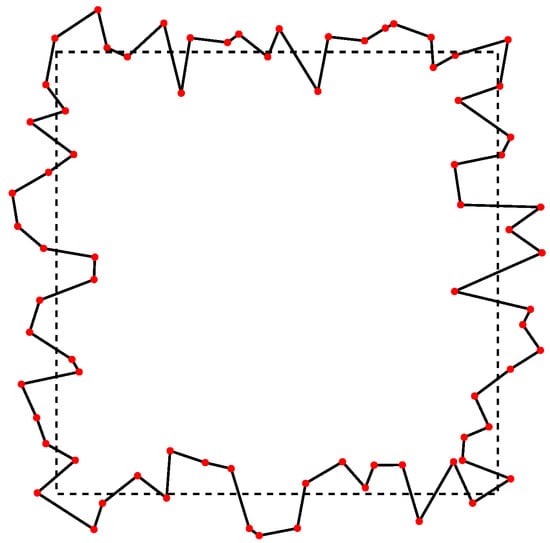
Figure 1.
A square cross-section with a randomly generated rough boundary and for relative roughness (namely, ).
3. Heat and Mass Transfer Analysis Model
The forced convection flow in the rough microchannel is assumed to be fully developed both dynamically and thermally. This means that we consider velocity and temperature depending just on the microchannel cross-section Cartesian coordinates . For this configuration, the velocity vector displays only one component , which is directed along the channel axis with constant average velocity . Moreover, the pressure gradient shows just the component which is constant. Since the configuration involves rough microchannels, the effect of the viscous dissipation is taken into account in the local energy balance equation due to the expected high velocity gradients close to the channel walls. The dimensionless local momentum balance equation and local energy balance equation for these types of two-dimensional problems are Poisson equations, considering that the momentum balance equation can be solved independently [46,47,48,49]. In particular, Bazant [48] points out the physical analogies between the Poisson equation of momentum transfer for unidirectional flows and other phenomena sharing the same type of equation, such as stochastic processes and electrokinetics in nanochannels. Mortensen et al. [49] consider the Poiseuille flow in straight channels under stationary conditions for various cross-sectional shapes. These authors establish a linear relation between the dimensionless geometrical correction factor and the dimensionless compactness number.
The dimensionless local momentum balance equation and the dimensionless local energy balance equation can be written as
where T is the dimensionless temperature, while the Poiseuille, Brinkman, and Nusselt numbers are defined as follows:
with
where the symbol denotes dimensional quantities, is a constant reference velocity, is the mean flow velocity, and is the cross-sectional area of the microchannel, while one can prove that is a constant denoted here with the symbol [46,47]. The average wall temperature , the bulk temperature , and the average wall heat flux are defined as
where is the normal outward direction to the perimeter . The scaling employed to obtain (2) and (3) is
where is the Cartesian coordinate vector and is the thermal conductivity of the fluid. We note that different numerical coefficients are present in (2) and (3) compared with the corresponding equations reported in Barletta et al. [46], Sphaier et al. [47]. The reason is that in (7), the scales involve the hydraulic diameter, while in Refs. [46,47], the nominal hydraulic radius is employed. If one considers (4)–(7), the definitions of Poiseuille and Nusselt numbers may be rewritten as
We note that the Poiseuille number represents the dimensionless parameter expressing the flow resistance. The boundary conditions imposed at the rough walls, and thus on the actual perimeter , are of no slip for the velocity and , , and for the temperature, namely
The first equality of the following equation can be obtained by integrating (3) over the cross-sectional surface and by employing boundary condition (9):
The second equality in (10) is obtained by evaluating the integral of the term. This result is achieved by multiplying (2) by u and then integrating by parts the resulting equation and employing the no-slip conditions.
We note that, for the case , one has , and hence ; then, from (10), the Brinkman number can be obtained, and not imposed, namely
where the subscript denotes that this Brinkman number refers to the imposed temperature condition (9).
Perfectly Smooth Square Microchannel Case and Mesh Independence Test
The case of a perfectly smooth square channel with negligible viscous dissipation is treated in [50] where an expression of the Poiseuille number
is reported. From (10), one obtains the following definitions of and :
where can be evaluated by employing (12). From Shah and London [50], one also obtains the values of and, from [51], one obtains the value of (both for the case ), namely
The data relative to the smooth case are employed here as a benchmark to test the numerical solver. The finite element method solver of Wolfram 14 (©Wolfram Research Inc., Champaign, IL, USA) is employed here to simulate both the velocity and temperature fields. The mesh employed to discretize the domain is unstructured and with triangular elements where the mesher option MaxCellMeasure specifies the maximum value of the area of a single triangular element.
Table 1 shows how the Poiseuille number and the Nusselt number vary as functions of the mesh refinement for the conditions and . Each row of Table 1 refers to a different value MaxCellMeasure. Based on the results reported in Table 1, the mesh resolution chosen for the computations is since it is a good trade-off between accuracy and computational effort. The data in Table 1 are obtained by considering the ideal (nominal) square geometry, , and negligible viscous dissipation, .

Table 1.
Mesh independence test: The mesh refinement chosen is . The data are obtained by considering the ideal square geometry, , and negligible viscous dissipation, .
It is worth reporting that different opportunities have been explored for the definition of the number of points to be employed for building the rough boundary, for instance, a number of points which is proportional to (see Figure 2). The choice of fixing the number of points to a reasonably low value, as we did, is functional to obtaining a fairly fast convergence to the smooth square shape for . One can note a convergence issue from Figure 2 where is imposed: the left-hand-side frame is obtained by fixing the number of points to 80, while the right-hand-side frame is obtained by defining the number of points as . It is clear that pushing the number of points to a fairly high number for would let the smooth limiting case recover only for a number of points which tends to infinity, obviously yielding numerical issues.
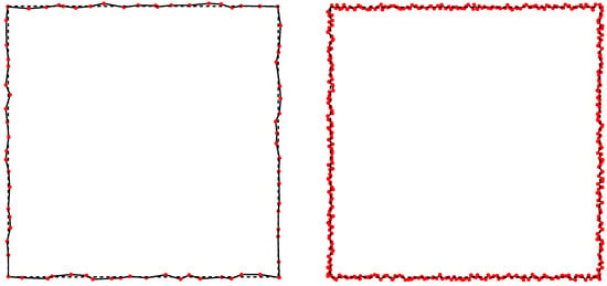
Figure 2.
Square cross-sections with randomly generated rough boundary and for relative roughness : the left-hand-side frame is obtained by employing 80 points, while the right-hand-side frame is drawn for points.
4. Results
The cases explored here focus on values of relative roughness . The value assures a good approximation of the smooth square case, while the case is, referring to Figure 1, a limiting case beyond which a massive distortion of the nominal square shape is obtained. Each point reported in the following figures is the result of a statistical averaging procedure over a sample of 1000 cases: each sample is obtained by setting the relative roughness and the value of Brinkman number . For a given sample of cases, each case corresponds to a different randomly generated rough geometry. The statistical analysis reported in the following figures presents the mean values, over the given sample, of the parameters of interest and also the statistical confidence intervals within one standard deviation of tolerance represented by the vertical bars.
The results relative to the hydrodynamics of the microchannel flow focus on the effect of the roughness on the hydraulic resistance: the behavior of the Poiseulle number as a function of the dimensionless relative roughness is reported in Figure 3. The limiting case of negligible roughness recovers the literature value reported in (12). The Poiseuille number is then, as expected, a monotonically increasing value of , denoting the increasing effort needed to let the fluid flow through the microchannel due to the presence of the roughness. The gray bars indicate the statistical confidence intervals within one standard deviation of tolerance, hence highlighting how the statistical sample spreads over its mean value for increasing roughness. This is a reasonable and expected result, especially if one considers Figure 1: having high values of implies more degrees of freedom in drawing the microchannel cross-section, which yields a strong variability in the velocity and temperature fields.
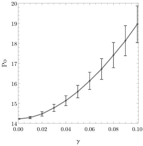
Figure 3.
Poiseuille number versus .
For what concerns the heat transfer, the Nusselt number is the parameter employed to measure the efficiency of the process. Figure 4 shows the Nusselt number and the Brinkman number , both for the boundary condition, versus the dimensionless relative roughness . One may note, as happens for the Poiseuille number, that the data displays a higher dispersion for high values of . This is again due to the geometry variability for such high value of relative roughness. The Nusselt in Figure 4 is a monotonically decreasing function of , meaning that the roughness introduces a deterioration in the heat transfer performances. The values of reported in the right-hand-side frame of Figure 4 are obtained by employing (11) and are a monotonically increasing function of .
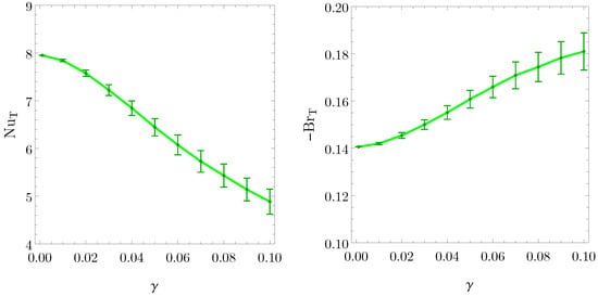
Figure 4.
Nusselt number for the boundary condition versus , left-hand-side frame. That minus the Brinkman number for the boundary condition versus , right-hand-side frame.
The behavior of the Nusselt number for and boundary conditions is reported in Figure 5 as a function of : on the left hand side one can find, in blue color, obtained for different values of , while, on the right hand side, one can find, in red color, obtained for different values of . For the cases and , in fact, the value of the Brinkman number cannot be obtained, as for the case, but it must be set to obtain the temperature profile. The data reported in Figure 5 shows a higher standard deviation for higher values of roughness as happens for the other parameters analyzed. One can deduce, from Figure 5, that is usually higher than , as expected from the literature. Moreover, one can conclude that is, once again, a decreasing function of : the roughness reduces the heat transfer performances of the microchannel. This occurs, in particular, for relatively low values of . We recall that measures the intensity of the viscous dissipation relative to the wall heat flux. It is worth noting that, for negligible viscous dissipation, , together with negligible roughness, , the Nusselt values reported in Table 1 are obtained.
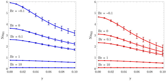
Figure 5.
Nusselt numbers for the boundary condition versus , blue color, left-hand-side frame. Nusselt number for the boundary condition versus , red color, right-hand-side frame. The case refers to negligible viscous dissipation.
Statistical Significance Test
A test of the statistical significance of the data obtained is performed here. The built-in tool of Wolfram, named DistributionFitTest, allows one to test how the distribution of a data sample follows the normal distribution. We performed this test on the Poiseuille number, , and Nusselt, , data samples, namely for every point reported in Figure 3 and Figure 4. The test result varies as a function of the data sample considered. A visual representation of the best and worst results, in terms of how the data follow the normal distribution, is reported in Figure 6 and Figure 7: the probability density of the actual data sample, represented by the histograms, is compared with the normal distribution obtained by employing the mean value and the standard deviation of the same data sample. In Figure 6 and Figure 7, two frames are reported for two different values of : the one on the left is relative to the best performing data sample, in terms of the normal distribution test, and the one on the right is relative to the worst performing data sample. One can notice that even the worst performing case yields a distribution which matches the normal distribution well. We conclude that data samples of 1000 elements are sufficient to obtain results with a satisfactory statistical significance.
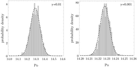
Figure 6.
Comparison between the data distribution, histogram, and the normal distribution built on the same data (dashed curve) for the Poiseuille number. The left-hand-side frame reports the best performing data sample, in terms of data recovering the normal distribution, while the right-hand-side frame reports the worst performing data sample. Each frame is obtained for a given relative roughness .
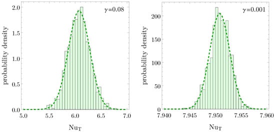
Figure 7.
Comparison between the data distribution, histogram in the case, and the normal distribution built on the same data (dashed curve) for the Nusselt number. The left-hand-side frame shows the best performing data sample, in terms of data recovering the normal distribution, while the right-hand-side shows the worst performing data sample. Each frame is obtained for a given relative roughness .
5. Conclusions
The role of boundary roughness in the heat and mass transfer for a forced fully developed flow in microchannels is investigated here. A statistical analysis is performed by producing a data sample of 1000 elements for each configuration considered. The heat transfer performance is evaluated by studying how the Nusselt number behaves as the roughness varies. From a hydrodynamic point of view, the Poiseuille number is employed to monitor the impact of the roughness on the hydraulic resistance. The main conclusions are listed below:
- The statistical analysis performed shows a satisfactory statistical significance; thus, the results can be considered statistically reliable.
- The analysis shows a general tendency for heat transfer performance to deteriorate as the relative roughness of the boundary walls increases (compared with the smooth microchannel case): the Nusselt number is a monotonic decreasing function of the relative roughness for the three possible boundary conditions considered, – – . This conclusion clashes with part of the results presented in the literature which states that roughness can increase the heat transfer performances. This issue may have a possible explanation: by assuming a fully developed flow, we neglect the effect of flow disruption in the axial direction possibly caused by the presence of a three-dimensional random roughness. The flow disruption, indeed, has been proven to enhance the heat and mass transfer performances.
- The analysis shows, from a hydrodynamic point of view, an increment in the Poiseuille number for increasing values of the relative roughness of the boundary walls. This implies an increasing mechanical power needed to support the fluid flow through the microchannel due to the presence of the roughness and, hence, a deterioration in the hydrodynamic performances for increasing values of relative roughness. This conclusion relates to the one just formulated for the heat transfer since they both highlight a deterioration effect of the roughness on the microchannel performances.
- These findings highlight the critical role of wall roughness in determining heat and mass transfer efficiency, emphasizing the need for a deeper understanding of roughness effects when designing microchannel systems.
We point out that a three-dimensional analysis is more realistic. However, losing the generality of the fully developed flow condition has severe drawbacks in the development of the analysis. One of the reasons is the drastic increase in the number of governing parameters (a dependence on the Reynolds number and Prandtl number is expected). Furthermore, for a three-dimensional approach, there is also a marked arbitrariness in the numerical model and, in particular, in the setting of the inlet and outlet conditions meant for closing the computational domain in the streamwise direction. These aspects, together with the significantly larger computational load (due, for instance, to the management of a three-dimensional mesh for each element of the statistical sample), led to the choice of adopting the two-dimensional scheme employed in the present analysis.
Author Contributions
Conceptualization, A.B., P.V.B., M.C., L.A.S. and G.V.; methodology, A.B., P.V.B., M.C., L.A.S. and G.V.; software, A.B., P.V.B., M.C., L.A.S. and G.V.; validation, A.B., P.V.B., M.C., L.A.S. and G.V.; formal analysis, A.B., P.V.B., M.C., L.A.S. and G.V.; investigation, A.B., P.V.B., M.C., L.A.S. and G.V.; resources, A.B., P.V.B., M.C., L.A.S. and G.V.; data curation, A.B., P.V.B., M.C., L.A.S. and G.V.; writing—original draft preparation, A.B., P.V.B., M.C., L.A.S. and G.V.; writing—review and editing, A.B., P.V.B., M.C., L.A.S. and G.V.; visualization, A.B., P.V.B., M.C., L.A.S. and G.V.; supervision, A.B., P.V.B., M.C., L.A.S. and G.V.; project administration, A.B., P.V.B., M.C., L.A.S. and G.V.; funding acquisition, A.B., P.V.B., M.C., L.A.S. and G.V. All authors have read and agreed to the published version of the manuscript.
Funding
This work was supported by Alma Mater Studiorum Università di Bologna through the RFO 2024 research grant.
Data Availability Statement
Data is contained within the article.
Conflicts of Interest
The authors declare no conflicts of interest.
References
- Bruus, H. Theoretical Microfluidics; Oxford University Press: Oxford, UK, 2007; Volume 18. [Google Scholar]
- Yarin, L.; Mosyak, A.; Hetsroni, G. Fluid Flow, Heat Transfer and Boiling in Micro-Channels; Springer: Berlin/Heidelberg, Germany, 2009. [Google Scholar]
- Cotta, R.M.; Knupp, D.C.; Naveira-Cotta, C.P. Analytical Heat and Fluid Flow in Microchannels and Microsystems; Springer: Cham, Switzerland, 2016; Volume 164. [Google Scholar]
- Kandlikar, S.; Garimella, S.; Li, D.; Colin, S.; King, M.R. Heat Transfer and Fluid Flow in Minichannels and Microchannels; Elsevier: Amsterdam, The Netherlands, 2005. [Google Scholar]
- Karniadakis, G.; Beskok, A.; Aluru, N. Microflows and Nanoflows: Fundamentals and Simulation; Springer Science & Business Media: New York, NY, USA, 2006; Volume 29. [Google Scholar]
- Gunnasegaran, P.; Mohammed, H.; Shuaib, N.; Saidur, R. The effect of geometrical parameters on heat transfer characteristics of microchannels heat sink with different shapes. Int. Commun. Heat Mass Transf. 2010, 37, 1078–1086. [Google Scholar] [CrossRef]
- Gulhane, N.P.; Mahulikar, S.P. Variations in gas properties in laminar micro-convection with entrance effect. Int. J. Heat Mass Transf. 2009, 52, 1980–1990. [Google Scholar] [CrossRef]
- Conder, T.E.; Solovitz, S.A. Computational optimization of a groove-enhanced minichannel. Heat Transf. Eng. 2011, 32, 876–890. [Google Scholar] [CrossRef]
- Kumar, V.; Paraschivoiu, M.; Nigam, K. Single-phase fluid flow and mixing in microchannels. Chem. Eng. Sci. 2011, 66, 1329–1373. [Google Scholar] [CrossRef]
- Colin, S. Gas microflows in the slip flow regime: A critical review on convective heat transfer. J. Heat Transfer. 2012, 134, 020908. [Google Scholar] [CrossRef]
- Ohadi, M.; Choo, K.; Dessiatoun, S.; Cetegen, E. Next Generation Microchannel Heat Exchangers; Springer: New York, NY, USA, 2013. [Google Scholar]
- Dixit, T.; Ghosh, I. Review of micro-and mini-channel heat sinks and heat exchangers for single phase fluids. Renew. Sustain. Energy Rev. 2015, 41, 1298–1311. [Google Scholar] [CrossRef]
- Khan, M.G.; Fartaj, A. A review on microchannel heat exchangers and potential applications. Int. J. Energy Res. 2011, 35, 553–582. [Google Scholar] [CrossRef]
- Qasem, N.A.; Zubair, S.M. Compact and microchannel heat exchangers: A comprehensive review of air-side friction factor and heat transfer correlations. Energy Convers. Manag. 2018, 173, 555–601. [Google Scholar] [CrossRef]
- Yu, Z.Q.; Li, M.T.; Cao, B.Y. A comprehensive review on microchannel heat sinks for electronics cooling. Int. J. Extrem. Manuf. 2024, 6, 022005. [Google Scholar] [CrossRef]
- Zhao, C.; Lu, T. Analysis of microchannel heat sinks for electronics cooling. Int. J. Heat Mass Transf. 2002, 45, 4857–4869. [Google Scholar] [CrossRef]
- Koo, J.M.; Im, S.; Jiang, L.; Goodson, K.E. Integrated Microchannel Cooling for Three-Dimensional Electronic Circuit Architectures. J. Heat Transf. 2005, 127, 49–58. [Google Scholar] [CrossRef]
- Jami F. Tullius, R.V.; Bayazitoglu, Y. A Review of Cooling in Microchannels. Heat Transf. Eng. 2011, 32, 527–541. [Google Scholar]
- Husain, A.; Kim, K.Y. Shape Optimization of Micro-Channel Heat Sink for Micro-Electronic Cooling. IEEE Trans. Components Packag. Technol. 2008, 31, 322–330. [Google Scholar] [CrossRef]
- Vafai, K.; Zhu, L. Analysis of two-layered micro-channel heat sink concept in electronic cooling. Int. J. Heat Mass Transf. 1999, 42, 2287–2297. [Google Scholar] [CrossRef]
- Xu, B.; Ooi, K.; Mavriplis, C.; Zaghloul, M. Evaluation of viscous dissipation in liquid flow in microchannels. J. Micromech. Microeng. 2002, 13, 53. [Google Scholar] [CrossRef]
- Koo, J.; Kleinstreuer, C. Viscous dissipation effects in microtubes and microchannels. Int. J. Heat Mass Transf. 2004, 47, 3159–3169. [Google Scholar] [CrossRef]
- Van Rij, J.; Ameel, T.; Harman, T. The effect of viscous dissipation and rarefaction on rectangular microchannel convective heat transfer. Int. J. Therm. Sci. 2009, 48, 271–281. [Google Scholar] [CrossRef]
- Nonino, C.; Del Giudice, S.; Savino, S. Temperature-dependent viscosity and viscous dissipation effects in microchannel flows with uniform wall heat flux. Heat Transf. Eng. 2010, 31, 682–691. [Google Scholar] [CrossRef]
- Jing, D.; Pan, Y.; Wang, X. Joule heating, viscous dissipation and convective heat transfer of pressure-driven flow in a microchannel with surface charge-dependent slip. Int. J. Heat Mass Transf. 2017, 108, 1305–1313. [Google Scholar] [CrossRef]
- Zhai, Y.; Xia, G.; Li, Z.; Wang, H. Experimental investigation and empirical correlations of single and laminar convective heat transfer in microchannel heat sinks. Exp. Therm. Fluid Sci. 2017, 83, 207–214. [Google Scholar] [CrossRef]
- Joy, A.; Shiblemon, K.; Baby, B. Review on fabrication and experimental study of microchannel heat sinks for cooling of electronic components. Mater. Today Proc. 2023, 72, 2985–2991. [Google Scholar] [CrossRef]
- Imaizumi, K.; Fujita, A.; Suzuki, A.; Kobashi, M.; Kato, M. Additive manufacturing for 3D microchannel structure using La (FexSi1-x) 13 magnetic refrigerant via laser powder bed fusion. Addit. Manuf. 2024, 83, 104076. [Google Scholar] [CrossRef]
- Akbari, Z.; Raoufi, M.A.; Mirjalali, S.; Aghajanloo, B. A review on inertial microfluidic fabrication methods. Biomicrofluidics 2023, 17, 051504. [Google Scholar] [CrossRef]
- Niculescu, A.G.; Chircov, C.; Bîrcă, A.C.; Grumezescu, A.M. Fabrication and applications of microfluidic devices: A review. Int. J. Mol. Sci. 2021, 22, 2011. [Google Scholar] [CrossRef]
- Darcy, H. Recherches Expérimentales Relatives au Mouvement de L’eau dans les Tuyaux; Mallet-Bachelier: Paris, France, 1857; Volume 1. [Google Scholar]
- Fanning, J.T. A Practical Treatise on Hydraulic and Water-Supply Engineering; Riple-Classic: Surrey, UK, 1899. [Google Scholar]
- Colebrook, C.F.; Blench, T.; Chatley, H.; Essex, E.; Finniecome, J.; Lacey, G.; Williamson, J.; Macdonald, G. Correspondence. turbulent flow in pipes, with particular reference to the transition region between the smooth and rough pipe laws. (includes plates). J. Inst. Civ. Eng. 1939, 12, 393–422. [Google Scholar] [CrossRef]
- Panda, S.; Kumar, R. A review on effect of various artificial roughness on heat transfer enhancement in a channel flow. J. Therm. Eng. 2021, 7, 1267–1301. [Google Scholar] [CrossRef]
- Nikuradse, J. Laws of Flow in Rough Pipes; NACA Technical Memorandum: Washington, DC, USA, 1950. [Google Scholar]
- Peiyi, W.; Little, W. Measurement of friction factors for the flow of gases in very fine channels used for microminiature Joule-Thomson refrigerators. Cryogenics 1983, 23, 273–277. [Google Scholar] [CrossRef]
- Mala, G.M.; Li, D. Flow characteristics of water in microtubes. Int. J. Heat Fluid Flow 1999, 20, 142–148. [Google Scholar] [CrossRef]
- Kandlikar, S. Roughness effects at microscale–reassessing Nikuradse’s experiments on liquid flow in rough tubes. Bull. Pol. Acad. Sci. Tech. Sci. 2005, 53, 343–349. [Google Scholar]
- Kandlikar, S.G. Exploring roughness effect on laminar internal flow–are we ready for change? Nanoscale Microscale Thermophys. Eng. 2008, 12, 61–82. [Google Scholar] [CrossRef]
- Mehendale, S.; Jacobi, A.; Shah, R. Fluid flow and heat transfer at micro-and meso-scales with application to heat exchanger design. Appl. Mech. Rev. 2000, 53, 175–193. [Google Scholar] [CrossRef]
- Maghrabie, H.M.; Olabi, A.; Sayed, E.T.; Wilberforce, T.; Elsaid, K.; Doranehgard, M.H.; Abdelkareem, M.A. Microchannel heat sinks with nanofluids for cooling electronic components: Performance enhancement, challenges, and limitations. Therm. Sci. Eng. Prog. 2023, 37, 101608. [Google Scholar] [CrossRef]
- Wu, P.; Little, W. Measurement of the heat transfer characteristics of gas flow in fine channel heat exchangers used for microminiature refrigerators. Cryogenics 1984, 24, 415–420. [Google Scholar] [CrossRef]
- Peng, X.; Peterson, G.; Wang, B. Heat transfer characteristics of water flowing through microchannels. Exp. Heat Transf. Int. J. 1994, 7, 265–283. [Google Scholar] [CrossRef]
- Weaver, S.; Barringer, M.D.; Thole, K.A. Microchannels with manufacturing roughness levels. J. Turbomach. 2011, 133, 041014. [Google Scholar] [CrossRef]
- Mandev, E.; Manay, E. Effects of surface roughness in multiple microchannels on mixed convective heat transfer. Appl. Therm. Eng. 2022, 217, 119102. [Google Scholar] [CrossRef]
- Barletta, A.; Celli, M.; Sphaier, L.; Brandão, P.; Lazzari, S.; Ghedini, E. Shape uncertainty analysis of laminar forced convection in a round microchannel with viscous dissipation. Appl. Therm. Eng. 2025, 265, 125536. [Google Scholar] [CrossRef]
- Sphaier, L.A.; Barletta, A.; Celli, M.; Brandão, P.V.; Ghedini, E. Laminar forced convection in circular microchannels with slip-flow: Analysis of randomly distributed roughness. Int. Commun. Heat Mass Transf. 2025, 162, 108615. [Google Scholar] [CrossRef]
- Bazant, M.Z. Exact solutions and physical analogies for unidirectional flows. Phys. Rev. Fluids 2016, 1, 024001. [Google Scholar] [CrossRef]
- Mortensen, N.A.; Okkels, F.; Bruus, H. Reexamination of Hagen-Poiseuille flow: Shape dependence of the hydraulic resistance in microchannels. Phys. Rev. E-Nonlinear Soft Matter Phys. 2005, 71, 057301. [Google Scholar] [CrossRef]
- Shah, R.; London, A. Laminar Flow Forced Convection in Ducts; Advances in Heat Transfer; Academic Press: Cambridge, MA, USA, 1969; Volume 1. [Google Scholar]
- Wang, C. H2 Forced Convection in Rounded Rectangular Ducts. J. Thermophys. Heat Transf. 2014, 28, 811–815. [Google Scholar] [CrossRef]


Disclaimer/Publisher’s Note: The statements, opinions and data contained in all publications are solely those of the individual author(s) and contributor(s) and not of MDPI and/or the editor(s). MDPI and/or the editor(s) disclaim responsibility for any injury to people or property resulting from any ideas, methods, instructions or products referred to in the content. |
© 2025 by the authors. Licensee MDPI, Basel, Switzerland. This article is an open access article distributed under the terms and conditions of the Creative Commons Attribution (CC BY) license (https://creativecommons.org/licenses/by/4.0/).