Abstract
The flow of a non-Newtonian, power-law fluid, directed normally to a horizontal cylinder with square cross-section (two-dimensional flow) is considered in the present paper. The problem is investigated numerically with a very large calculation domain in order that the flow could be considered unconfined. The investigation covers the power-law index from 0.1 up to 2 and the Reynolds number ranges from 60 to 160. Over this range of Reynolds numbers the flow is unsteady. It is found that the drag coefficient and the Strouhal number are higher in a confined flow compared to those of an unconfined flow. In addition some flow characteristics are lost in a confined flow. Complete results for the drag coefficient and Strouhal number in the entire shear-thinning and shear-thickening region have been produced. In shear-thinning fluids chaotic structures exist which diminish at higher values of power-law index. This study represents the first investigation of unsteady, non-Newtonian power-law flow past a square cylinder in an unconfined field.
1. Introduction
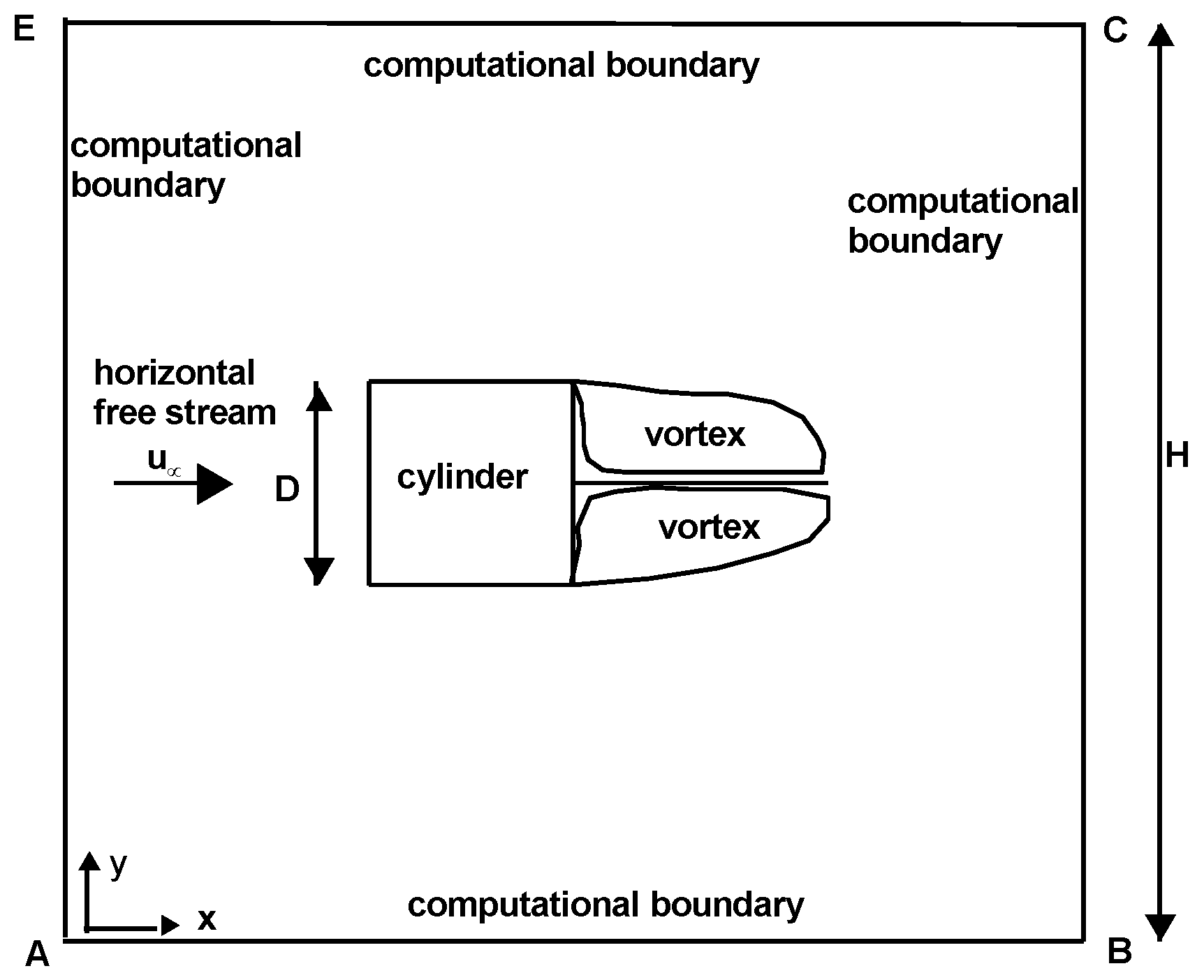
One important quantity for any flow normal to a cylinder is the drag coefficient, which is calculated both experimentally and numerically. However, the boundaries of the calculation of the drag coefficient, either experimentally or numerically, are inevitable. The experimental calculation is made in wind tunnels where these boundaries are the walls of the wind tunnel and in the numerical calculation these boundaries are the boundaries of the calculation domain (Figure 1). The flow past any body immersed in a stream bounded by rigid walls is subject to what is commonly called blockage constraint. The rigid boundaries prevent a free lateral displacement of the flow by the body, in the neighbourhood of which velocities are higher than they would be in an unlimited stream. “The question is: Does the presence of the walls modify the results in a substantial way? Can we make the walls so far away that the flow around the cylinder can be isolated and the walls thought of as infinitely far? The answer depends on the Reynolds number. If the Reynolds number is zero, the answer is no. However, for any Reynolds number Re > 0, it is thought that the flow may be isolated and the presence of the walls ignored” [1].
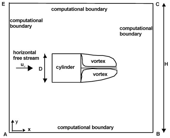
Figure 1.
The flow configuration and coordinate system.
Little attention has been given to wall constraint on the flow past a bluff body since Glauert’s treatment of the two-dimensional problem in 1933 [2]. Glauert’s interest in the problem appears to have been stimulated by existing experiments on the flow past an inclined flat plate in a wind tunnel. He pointed out the nature of the blockage effect associated with the body wake and proposed a theory, based in part upon the Helmholtz model of the flow past a bluff body. Glauert proposed a correction formula connecting the drag coefficient, which corresponds to an unlimited stream to the drag of the confined situation. Later a better correction formula was proposed in 1963 by Maskell [3]. Using these formulas the bounded results are corrected and made suitable for an unbounded domain (see for example the work of Najjar and Vanka, [4]).
Transforming the unbounded domain into a finite domain is an approximation, but it really helps [1]. If the domain is small one gets only the gross qualitative behavior but if the domain is large the accuracy is high. In the field of numerical investigation some researchers used very large computational domains to avoid the influence of the boundaries on the results. Stojkovic et al. [5] used a calculation domain 1000 ≤ H/D ≤ 100,000 depending on the Reynolds number for the study of a rotating circular cylinder. The authors mention that “For decreasing Reynolds numbers the size of the integration domain has to be enlarged significantly”. Posdziech and Grundmann [6] investigated the flow normal to a circular cylinder at Reynolds numbers 5 ≤ Re ≤ 250 by means of a spectral element method in a computational domain of H/D = 8000. Sen et al. [7] used a computation domain H/D = 8000 to study the steady flow past a stationary circular cylinder at 6 ≤ Re ≤ 40. It is seen that, in many works concerning the flow past a cylinder, large computational domains have been used in order to avoid the influence of the boundaries on the results. It is reminded here that the drag coefficient is strongly dependent on the size of the computational domain and increases exponentially with a decreasing domain size. The reduction of the drag coefficient and Strouhal number with an increase in the computational domain is shown in Figures 5 and 6 in Posdziech and Grundmann [6]. It is true that the effect of blockage is more significant at lower Reynolds numbers, but it also influences the results at higher Re numbers.
The work of Sahu et al. [8] is the most complete work of unsteady non-Newtonian flow past a square cylinder. The investigation covered the Reynolds number range from 60 up to 160 and the power-law index from 0.5 up to 2. The domain size was H/D = 20. However, this domain size is considered low for the flow in an unconfined flow. The target of the present work is to present results in an unconfined flow with H/D = 50,000 covering also the power-law range 0.1 ≤ n < 0.5, which is missing from the literature.
2. The Mathematical Model and Numerical Code
Consider the flow of a non-Newtonian power-law fluid across a horizontal square cylinder as it is shown in Figure 1. The full equations of this flow [9] are continuity equations:
x-momentum equation:
y-momentum equation:
The relation between the stress tensor and the rate-of-strain tensor is the following:
where is the apparent viscosity and the strain tensor is:
Taking into account the Equations (4) and (5), the momentum equations takes the form x-momentum equation:
y-momentum equation:
where is the horizontal coordinate, is the vertical coordinate, is the horizontal velocity, is the vertical velocity, is the pressure and is the fluid density. The apparent viscosity is:
where n is the power-law index and K is the consistency coefficient which reduces to dynamic viscosity in the case of Newtonian fluids. The fluid is characterized as shear-thinning for 0 < n < 1, shear-thickening for n > 1, and Newtonian for n = 1. In the shear-thinning regime with a low power-law index (n = 0.2) belong polymer melts and rubber, whereas aggregates with particles belong to the shear-thickening regime with high n.
The flow is governed by the Reynolds number, which is given by the following relationship:
where D is the length of the cylinder side (Figure 1) and is the free stream velocity. The drag and lift coefficients are defined as:
where and are the horizontal and vertical forces acting on the cylinder. The Strouhal number is defined as:
where f is the frequency of vortex shedding.
The present numerical study has been carried out using ANSYS FLUENT (version 12.0). The two-dimensional, unsteady, laminar solver was used with the third-order MUSCL scheme for the convective terms in the momentum equation. The coupled scheme was used for pressure–velocity coupling and the non-Newtonian power-law model was used for viscosity. An implicit time scheme was used with a non-dimensional time step of 0.01. Another smaller non-dimensional time step was used but the results remained unaffected. A double precision accuracy was used and a convergence criterion of 10−10 was used for the x- and y-velocity components, as well as for the residuals of continuity. In order to treat an unbounded domain the four computational boundaries were placed far away from the cylinder (at distance 25,000D in all directions) with AB = BC = CE = EA = 50,000D. The grid near the surface of the cylinder was sufficiently fine in order to adequately resolve the flow characteristics near the cylinder. For the refinement of the grid at the cylinder surface the grid-adaptation function of ANSYS FLUENT was used. This very large calculation domain has been used by the present author in three recent papers [10,11,12].
The applied boundary conditions (Figure 1) are the following according to the ANSYS FLUENT code. The boundary AE was defined as “velocity inlet” where the horizontal velocity is constant and the vertical velocity is zero, as follows:
The boundary BC was defined as “outflow”. This boundary condition, according to FLUENT, assumes that all flow variables have zero normal gradient except pressure. Therefore, the following relation is valid:
The boundaries AB and EC were defined as a horizontal “moving wall”. It was assumed that the wall was moving with velocity equal to the free stream velocity, whereas the velocity normal to the horizontal moving wall was zero, as follows:
The four cylinder sides were defined as “stationary walls” (no slip condition).
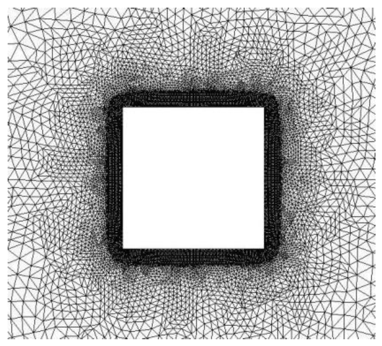
In Table 1 a mesh resolution test is presented for two power-law indices and a Reynolds number equal to 100. It is seen that, with increasing the number of grid points, the values of drag coefficients take their final values and a further increase of the grid points has no influence on the results. This technique has been used in all cases of the present work; that is, the number of grid points has been increased in each case until the values of the drag coefficient and Strouhal number became constant. For the addition of more grid points the grid-adaptation function of ANSYS FLUENT was used. The unstructured mesh used in the present work is shown in Figure 2.

Table 1.
Values of drag coefficient for Re = 100, n = 0.5 and n = 1.6 (mesh resolution test).
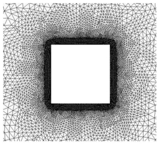
Figure 2.
The unstructured mesh around the cylinder.
3. Results and Discussion
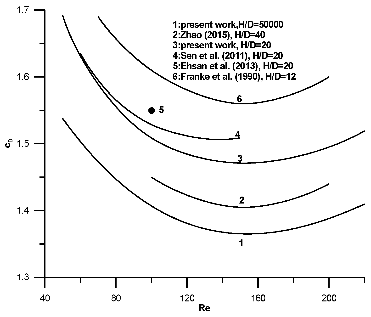
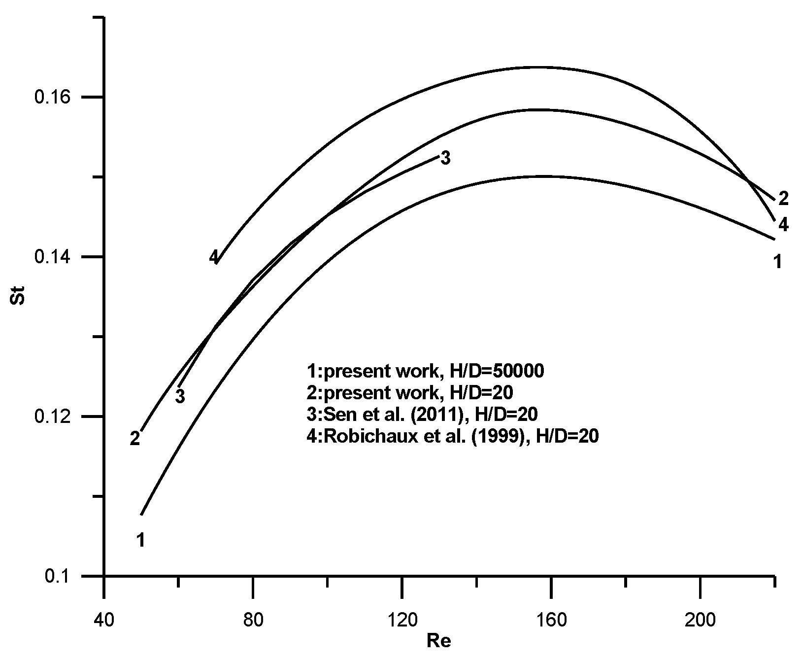
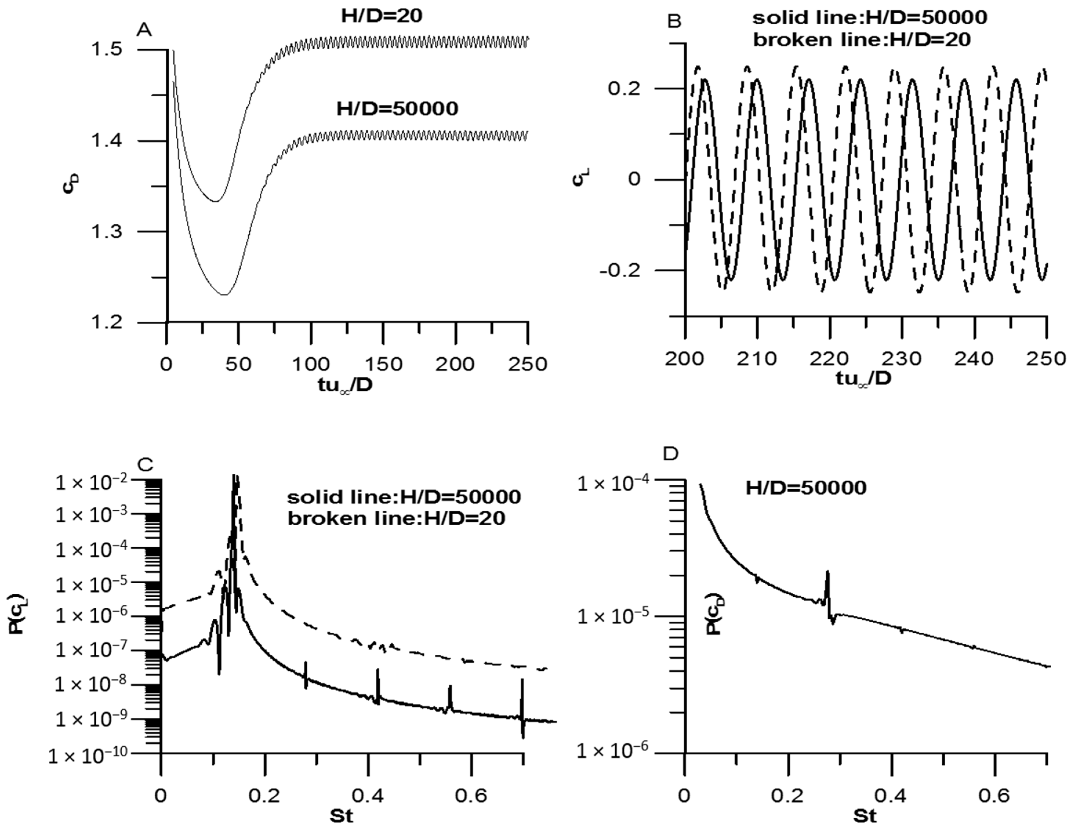
Results of the drag coefficient are shown in Figure 3 for a Newtonian fluid. In the same figure results from Franke et al. [13], Sen et al. [14], Ehsan et al. [15], and Zhao [16] are included for comparison. In the same figure results from the present work are included for the cases H/D = 50,000 and H/D = 20. The following conclusion can be drawn from Figure 3. As the distance H/D decreases the drag coefficient increases in agreement with the previous literature review. The results of the present work compare well with those of Sen et al. [14] for the same H/D and this a validation test about the efficiency of the present method. In Figure 4 results are presented for the Strouhal number, including those of Sen et al. [14] and Robichaux et al. [17]. It is seen that, as the distance H/D decreases, the Strouhal number increases again in agreement with the previous literature review. The results of the present work compare well again with those of Sen et al. [14] for the same H/D and this a second validation test about the efficiency of the present method. The results of drag coefficient and Strouhal number for the case H/D = 50,000 are the first results in the literature for a Newtonian fluid in an unconfined flow. In Figure 5 times histories and power spectra for drag and lift coefficients are shown for a Newtonian fluid at Re = 100. The fluctuation of lift coefficient is much higher than that of the drag coefficient. In addition for both the drag and lift coefficient the fluctuation is higher for H/D = 20 compared to that of the case with H/D = 50,000. In Figure 5C it is seen that the large computational domain allows some minor frequencies (superharmonics) to appear, whereas these minor frequencies disappear in the narrow computational domain. After the above comparisons results for the non-Newtonian fluids are presented.
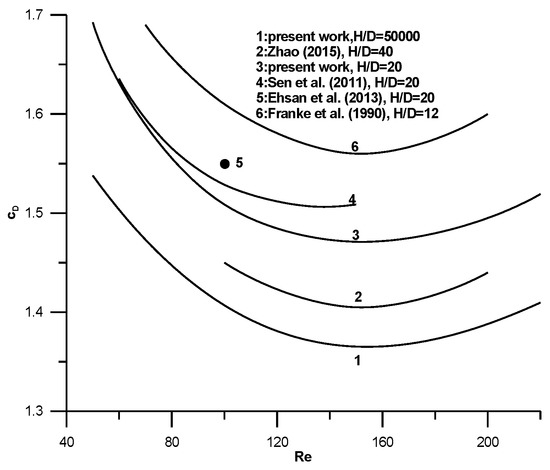
Figure 3.
Variation of drag coefficient across a square cylinder for a Newtonian fluid as a function of Reynolds number at different non-dimensional heights of computational domain.
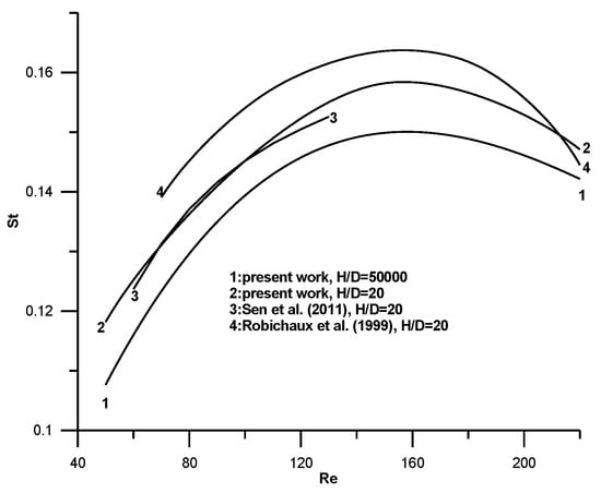
Figure 4.
Variation of Strouhal number in a square cylinder for a Newtonian fluid as a function of the Reynolds number at different non-dimensional heights of the computational domain.
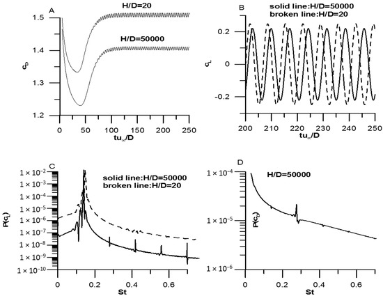
Figure 5.
Unsteady flow for a Newtonian fluid with Re = 100: (A) time series for ; (B) time series for ; (C) power spectrum for ; and (D) power spectrum for .
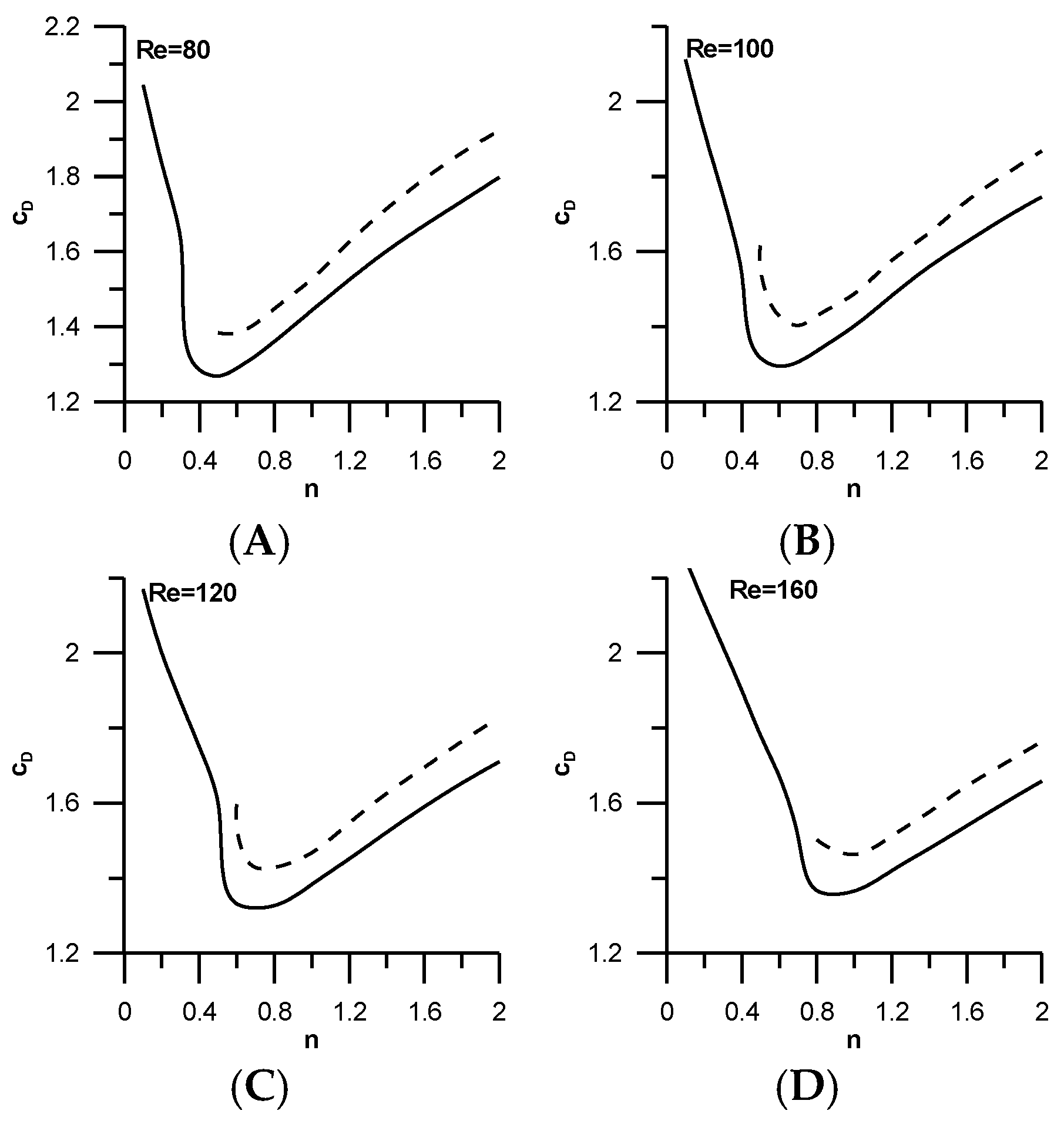
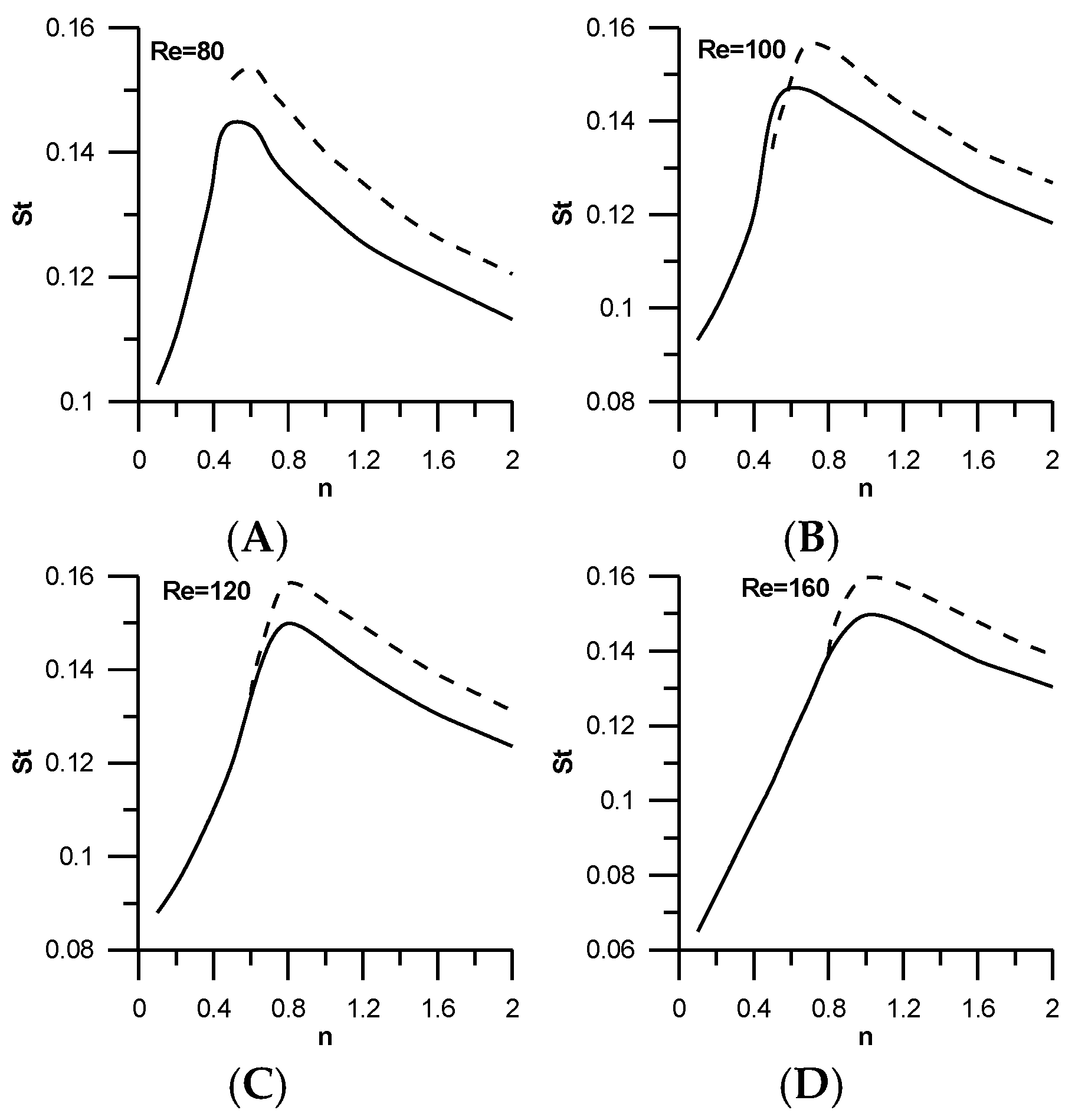
In Figure 6 and Figure 7 values of the drag coefficient and Strouhal number are presented for shear-thinning and shear-thickening fluids for different Reynolds numbers for an unconfined fluid with H/D = 50,000. In the same figures the results of Sahu et al. [8] with H/D = 20 are included. The same trend is seen here. The results of Sahu et al. [8] with the narrow computational domain are higher in all cases, as happens in Newtonian fluids, and in agreement with the literature review. Nikfarjam and Sohankar [18] investigated the flow of a power-law fluid over two tandem square cylinders in the Reynolds range Re = 60–160 and power-law index n = 0.7–1.4. In addition they presented some results for a single cylinder and n = 1.4. In Table 2, a comparison is made between the present results and those of Nikfarjam and Sohankar [18]. It is seen that the present results are lower than those of Nikfarjam and Sohankar [18] in all cases, as happens with the results of Sahu et al. [8]. This happens because their calculation domain was H/D = 20, whereas the calculation domain in the present work is H/D = 50,000. In addition, results in the power-law range 0.1 ≤ n < 0.5, which are missing from the literature, are presented by the present work.
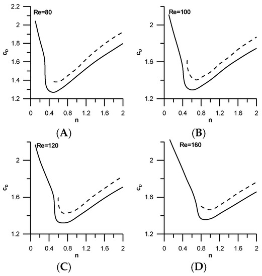
Figure 6.
Values of drag coefficients for different Reynolds numbers for shear-thinning and shear-thickening fluids: (A) Re = 80; (B) Re = 100; (C) Re = 120; (D) Re = 160. The solid line represents the present work with H/D = 50,000; the broken line represents the work of Sahu et al. [8] with H/D = 20.
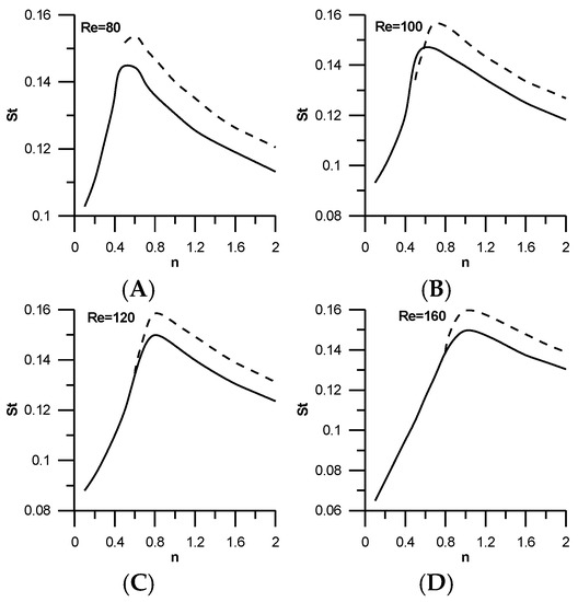
Figure 7.
Values of Strouhal number for different Reynolds numbers for shear-thinning and shear-thickening fluids: (A) Re = 80; (B) Re = 100; (C) Re= 120; (D) Re = 160. The solid line represents the present work with H/D = 50,000; the broken line represents the work of Sahu et al. [8] with H/D = 20.

Table 2.
Comparison of drag coefficients and Strouhal numbers for n = 1.4 and different Reynolds numbers.
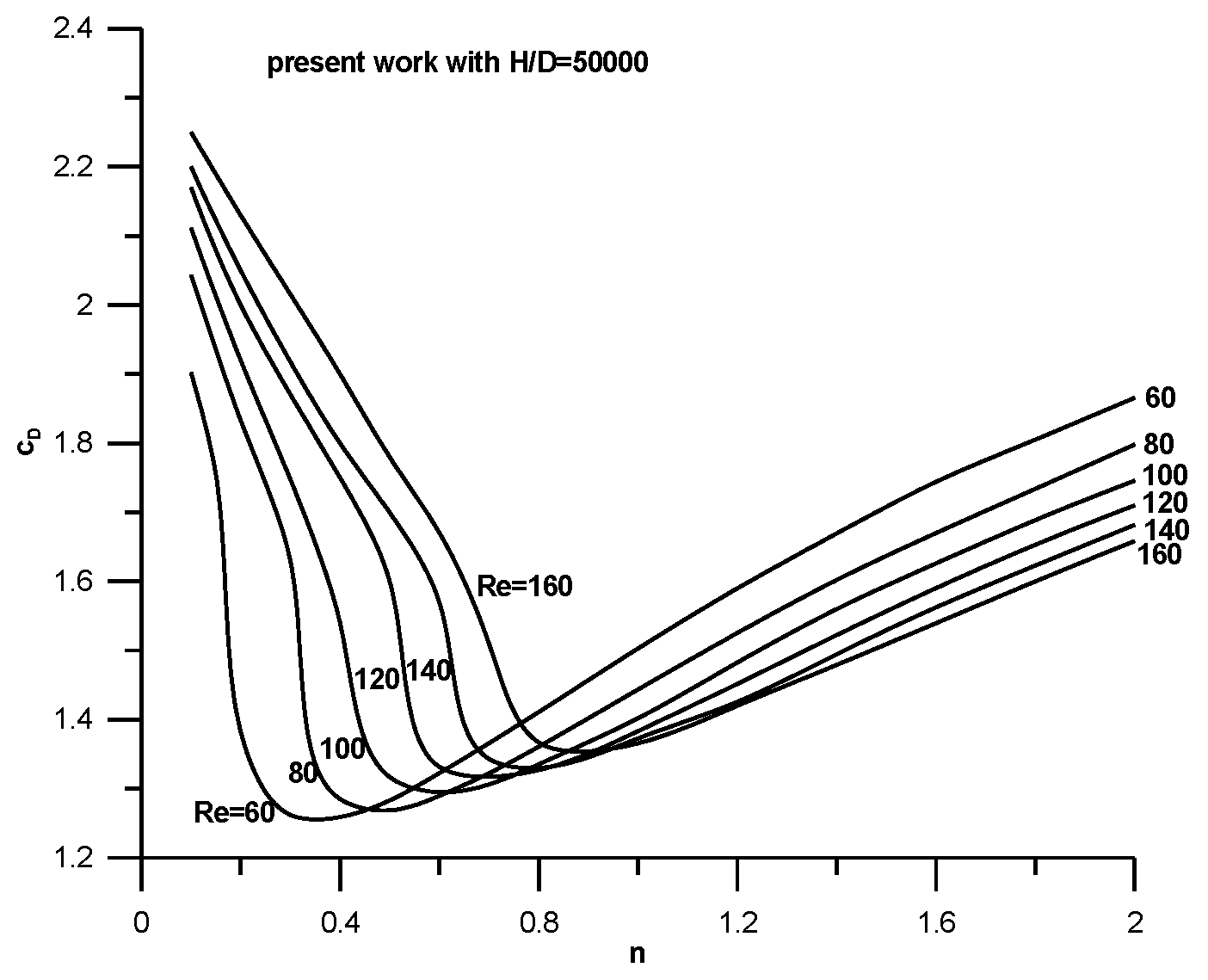
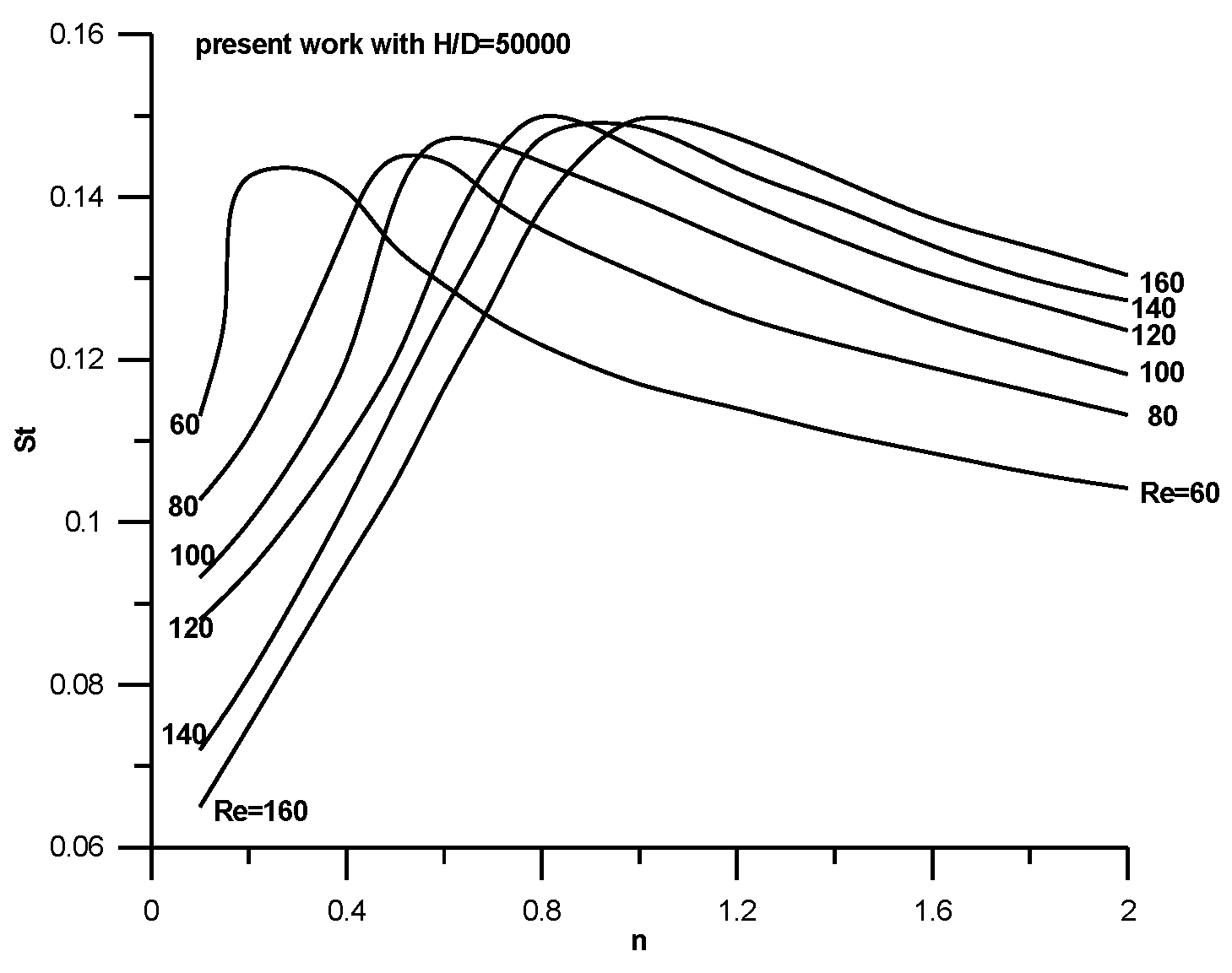
All results for the drag coefficient and Strouhal number for an unconfined flow are shown in Figure 8 and Figure 9 covering the range . For a fixed Re number the drag coefficient is high in the shear-thinning region, reducing with an increase in the power-law index, acquiring a minimum and then growing as the power-law index reaches higher values (shear-thickening region). The position of the minimum depends on the Re number and moves to higher n values as the Re number increases, but all minimum positions lay in the shear-thinning region. In general, the drag coefficient grows with the Re number in the shear-thinning region in contrast to what happens in the shear-thickening region where an increase of Re produces lower value of drag coefficient. The variation of the Strouhal number is opposite to that of drag coefficient, as can be seen in Figure 9. For a fixed Re number, the St number is low in shear-thinning regions, growing with an increase in the power-law index, reaching a maximum and then reducing as the power-law index reaches higher values (shear-thickening region). The position of the maximum depends on the Re number and moves to higher n values as the Re number increases, but all maximum positions lay in the shear-thinning region. In general the St number reduces with an increase in the Re number in the shear-thinning region and grows with an increase in the Re in the shear-thickening region.
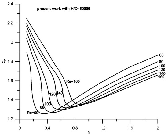
Figure 8.
Values of the drag coefficient for different Reynolds numbers for shear-thinning and shear-thickening fluids in an unconfined field.
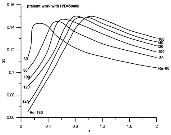
Figure 9.
Values of the Strouhal number for different Reynolds numbers for shear-thinning and shear-thickening fluids in an unconfined field.
The correlation between Figure 8 and Figure 9 is remarkable and shows that the drag coefficient reaches a minimum when the Strouhal number reaches a maximum.
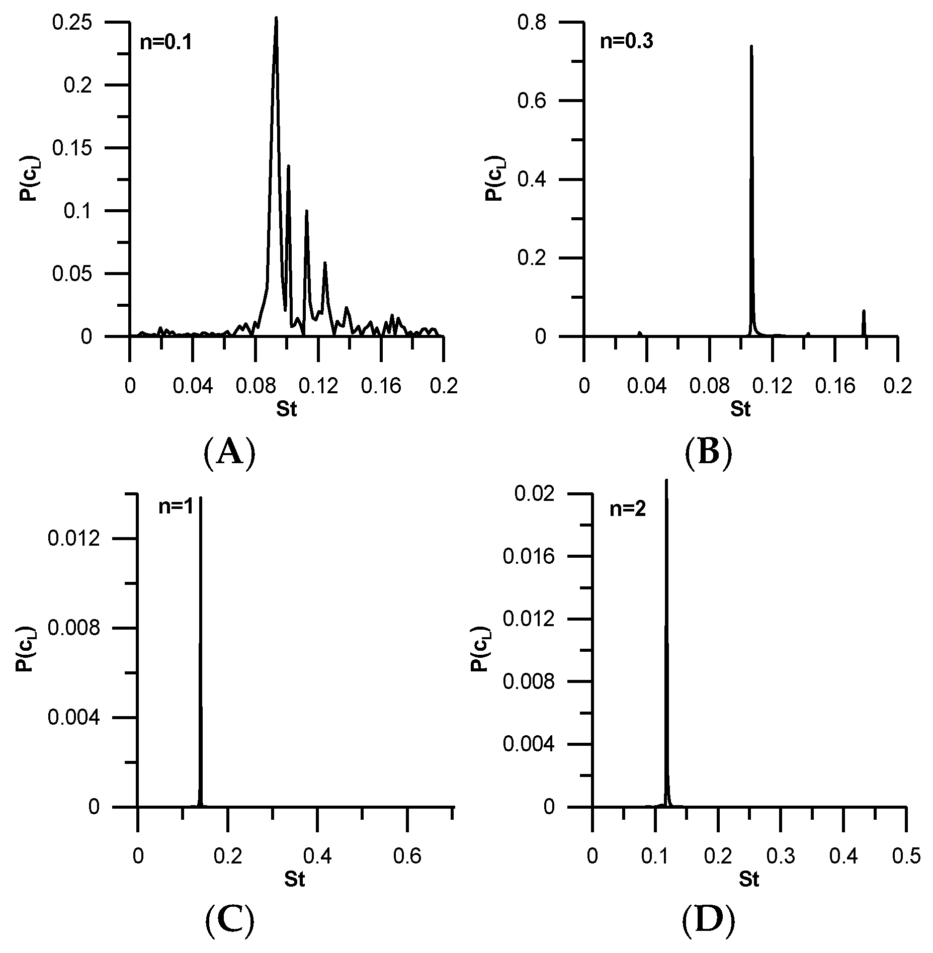
Some qualitative results are shown in the next figures. In Figure 10 the power spectra of the lift coefficient for Re = 100 and different values of the power-law index are presented. It is seen that in shear-thinning fluids with very low n (Figure 10A), except for the dominant frequency, many minor frequencies appear. This means that, in this range, chaotic structures exist. However, as the power-law index increases, these chaotic structures tend to disappear. Higher frequencies also appear in other unsteady investigations in bluff bodies (see page 64 in Tomboulides and Orszag [19] and page 3173 in Stojkovich et al. [5]). Drikakis [20] and Neofytou and Drikakis [21] numerically investigated the laminar incompressible flows in symmetric plane sudden expansions for Newtonian and non-Newtonian fluids, respectively. They found that large vortices either on the upper or the lower wall appeared and were purely random, as happens with the chaotic structures appearing at minor frequencies of the present work.
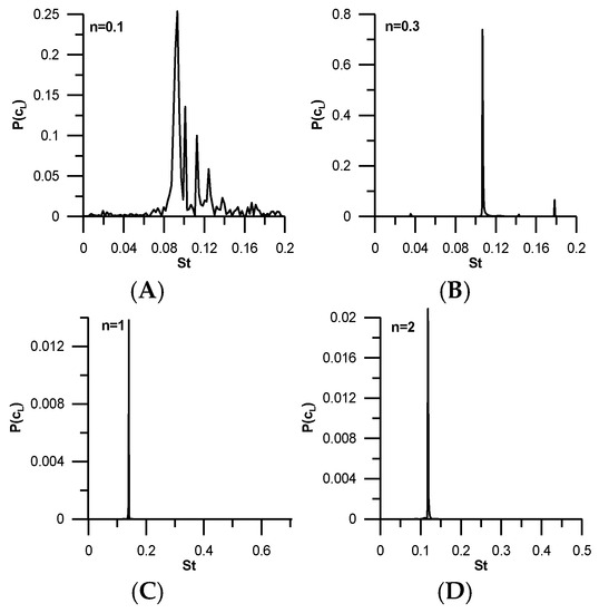
Figure 10.
Power spectra of the lift coefficient for Re = 100 and different values of the power-law index: (A) n =0.1; (B) n = 0.3; (C) n = 1; (D) n = 2.
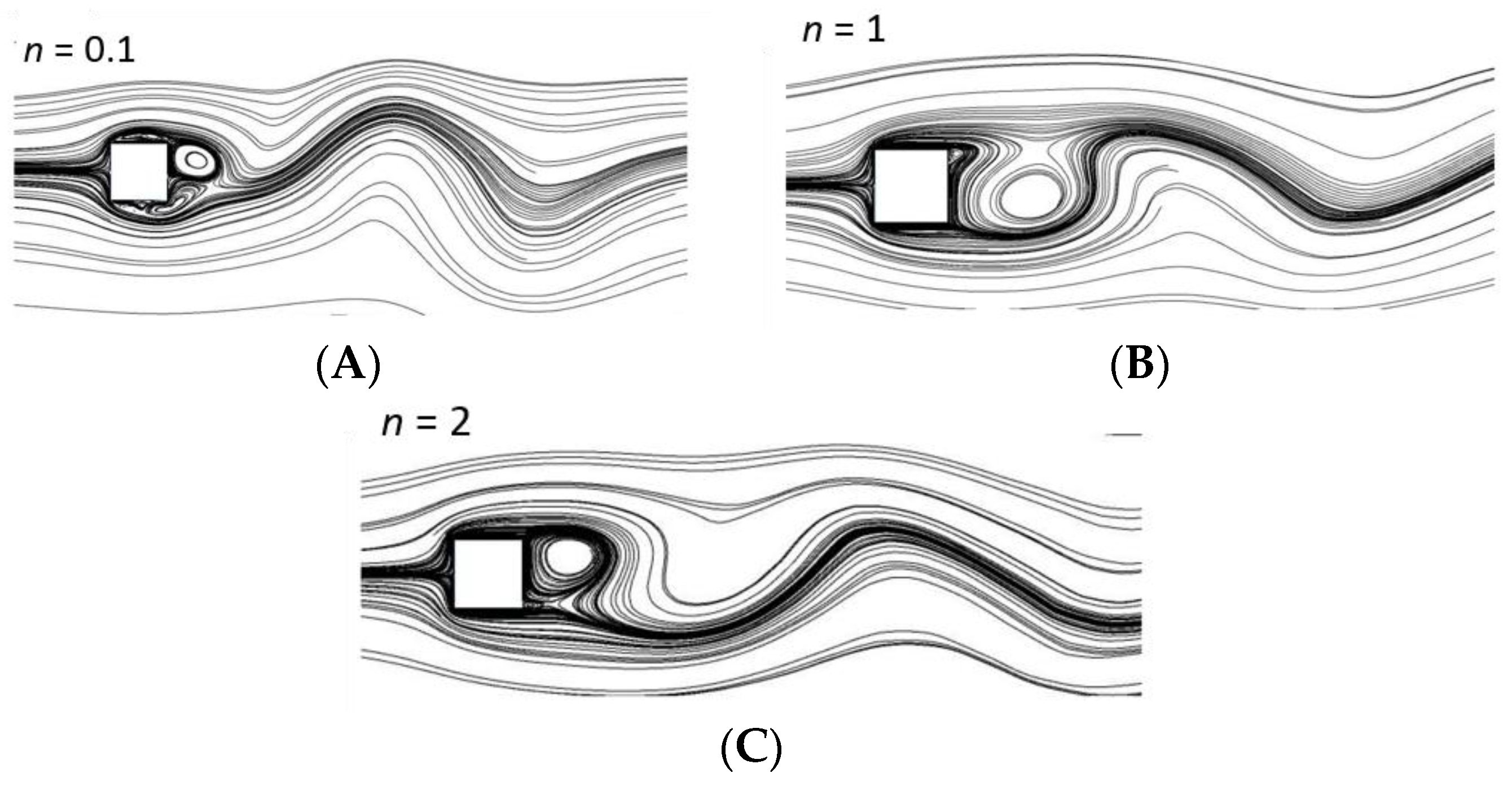
Figure 11 shows the vortex street for Re = 100 and different values of the power-law index.
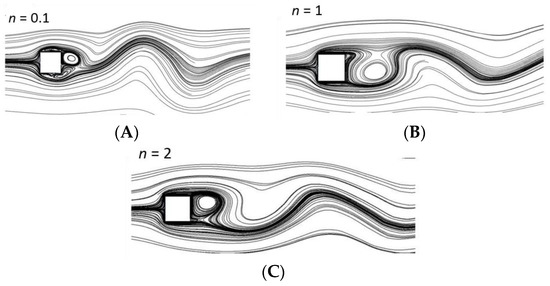
Figure 11.
Instantaneous streamlines for Re = 100 and (A) n = 0.1, (B) n = 1, and (C) n = 2.
4. Conclusions
The unsteady flow of a non-Newtonian power-law fluid past a square cylinder in an unconfined field has been investigated in the present paper at Reynolds numbers between 60 and 160 and power-law index between 0.1 and 2. The main findings are:
- The drag coefficient and the Strouhal number are higher in a confined flow compared to those of an unconfined flow. This is valid both for Newtonian and non-Newtonian fluids.
- In a confined flow some minor frequencies are suppressed and disappear. This means that some flow characteristics are lost in a confined flow.
- Complete results for the drag coefficient in the entire shear-thinning and shear-thickening region have been produced. Each drag curve is high at low and high power-law index values and shows a minimum at the shear-thinning region.
- The influence of the Re number on the drag coefficient is opposite in shear-thinning and shear-thickening regions. In the first the increases with increasing Re and in the second the decreases with increasing Re.
- Complete results for the Strouhal number in the entire shear-thinning and shear-thickening region have been produced. Each St curve is low at low and high power-law index valuesand shows a maximum at the shear-thinning region.
- The influence of the Re number on the St number is opposite in shear-thinning and shear-thickening regions. In the first, the St decreases with increasing Re and, in the second, the St increases with increasing Re.
- A remarkable correlation exists between the drag coefficient and the Strouhal number. The drag coefficient becomes minimum when the Strouhal number reaches its maximum.
- In shear-thinning fluid chaotic structures exist which diminish at higher values of the power-law index.
Conflicts of Interest
The authors declare no conflict of interest.
References
- Panton, R.L. Incompressible Flow, 3nd ed.; Wiley: Hoboken, NJ, USA, 2005. [Google Scholar]
- Glauert, H. Wind Tunnel Interference on Wings, Bodies and Airscrews; Aeronautical Research Committee Reports and Memoranda, No. 1566; Aeronautical Research Council: London, UK, 1933. [Google Scholar]
- Maskell, E.C. A Theory of the Blockage Effects on Bluff Bodies and Stalled Wings in a Closed Wind Tunnel; Aeronautical Research Committee Reports and Memoranda, No. 3400; Aeronautical Research Council: London, UK, 1963. [Google Scholar]
- Najjar, F.M.; Vanka, S.P. Simulations of the unsteady separated flow past a normal flat plate. Int. J. Numer. Methods Fluids 1995, 21, 525–547. [Google Scholar] [CrossRef]
- Stojkovich, D.; Breuer, M.; Durst, F. Effect of high rotation rates on the laminar flow around a circular cylinder. Phys. Fluids 2002, 14, 3160–3178. [Google Scholar] [CrossRef]
- Posdziech, O.; Grundmann, R. A systematic approach to the numerical calculation of fundamental quantities of the two-dimensional flow over a circular cylinder. J. Fluids Struct. 2007, 23, 479–499. [Google Scholar] [CrossRef]
- Sen, S.; Mittal, S.; Biswas, G. Steady separated flow past a circular cylinder at low Reynolds numbers. J. Fluid Mech. 2009, 620, 89–119. [Google Scholar] [CrossRef]
- Sahu, A.K.; Chabra, R.P.; Eswaran, V. Two-dimensional unsteady laminar flow of a power law fluid across a square cylinder. J. Non-Newton. Fluid Mech. 2009, 160, 157–167. [Google Scholar] [CrossRef]
- Denier, J.P.; Dabrowski, P.P. On the boundary-layer equations for power-law fluids. Proc. R. Soc. Lond. A 2004, 460, 3143–3158. [Google Scholar] [CrossRef]
- Pantokratoras, A. Steady flow of a non-Newtonian Carreau fluid across an unconfined circular cylinder. Meccanica 2016, 51, 1007–1016. [Google Scholar] [CrossRef]
- Pantokratoras, A. Steady flow of power-law fluids across a circular rotating cylinder. Prog. Comput. Fluid Dyn. 2016, 61, 6035–6046. [Google Scholar] [CrossRef]
- Pantokratoras, A. Steady flow of power-law fluids across an unconfined square cylinder. J. Appl. Mech. Tech. Phys. 2016, 57, 264–274. [Google Scholar] [CrossRef]
- Franke, R.; Rodi, W.; Schonung, B. Numerical calculation of laminar vortex-shedding flow past cylinders. J. Wind Eng. Ind. Aerodyn. 1990, 35, 237–257. [Google Scholar] [CrossRef]
- Sen, S.; Mittal, S.; Biswas, G. Flow past a square cylinder at low Reynolds numbers. Int. J. Numer. Methods Fluids 2011, 67, 1160–1174. [Google Scholar] [CrossRef]
- Ehsan, I.; Mohammad, S.; Reza, N.; Ali, J.; Tashnizi, E. Power-law Fluid flow Passing Two Square Cylinders in Tandem Arrangement. J. Fluids Eng. 2013, 135, 061101. [Google Scholar] [CrossRef]
- Zhao, M. Flow-induced vibrations of square and rectangular cylinders at low Reynolds number. Fluid Dyn. Res. 2015, 47, 025502. [Google Scholar] [CrossRef]
- Robichaux, J.; Balachandar, S.; Vanka, S.P. Three-dimensional Floquet instability of the wake of square cylinder. Phys. Fluids 1999, 11, 560–578. [Google Scholar] [CrossRef]
- Nikfarjam, F.; Sohankar, A. Power-law fluids flow and heat transfer over two tandem square cylinders: Effects of Reynolds number and power-law index. Acta Mech. 2013, 224, 1115–1132. [Google Scholar] [CrossRef]
- Tomboulides, A.; Orszag, S.A. Numerical investigation of transitional and weak turbulent flow past a sphere. J. Fluid Mech. 2000, 416, 45–72. [Google Scholar] [CrossRef]
- Drikakis, D. Bifurcation phenomena in incompressible sudden expansion flows. Phys. Fluids 1997, 9, 76–87. [Google Scholar] [CrossRef]
- Neofytou, P.; Drikakis, D. Non-Newtonian flow instability in a channel with a sudden expansion. J. Non-Newton. Fluid Mech. 2003, 111, 127–150. [Google Scholar] [CrossRef]
© 2016 by the authors; licensee MDPI, Basel, Switzerland. This article is an open access article distributed under the terms and conditions of the Creative Commons Attribution license ( http://creativecommons.org/licenses/by/4.0/).

