Data from Experimental Analysis of the Performance and Load Cycling of a Polymer Electrolyte Membrane Fuel Cell


 and
and
Abstract
:1. Summary
- Firstly, cell performance experiments, where the polarization curves were recorded for different operating conditions. All testing conditions were variations with respect to reference conditions representative of automotive applications. By doing this, the impact of different variations in the temperature of the cell, pressure of reactants, or cathode stoichiometry could be analyzed. The operating conditions tested are indicated in Table 1 [1]. For the cell performance experiments, most of the operating conditions were repeated three times in order to enable reproducibility of the experiments, as described in [1].
- Second, durability experiments, where an example of the application of load changes according to the New European Driving Cycle (once adapted to fuel cells as indicated in [2]) is provided. This data set contains data of the polarization curve at the beginning of the test and at the end of the test in order to assess the eventual cell degradation, which was discussed in Ramírez-Cruzado et al. [1].
- Spanish Ministry of Science, Innovation and Universities, grant number ENE2017-91159-EXP (Bio-inspired designs for bipolar plates of PEM Fuel Cells with optimized water management);
- Spanish Ministry of Economy and Competitiveness, grant number UNSE15-CE2962 (Characterization and optimization of fuel cells for their integration in mobile and stationary applications).
2. Data Description
- Cell_Performance_Data. This folder contains four subfolders, corresponding to the different groups of tests indicated in Table 1, named Reference_Conditions_tests, Cell_Pressure_tests, Cell_Temperature_tests, and Cathode_stoichiometry_tests. Each of the subfolders contains the original raw data files (compressed in .rar) corresponding to the different operating conditions for this group of tests, as follows:
- ○
- Reference_Conditions_tests contains the Reference Conditions test;
- ○
- Cell_Temperature_tests contains Temperature_70C.rar and Temperature_85C.rar;
- ○
- Cell_Pressure_tests contains Pressure_anode160kPa_cathode140kPa.rar and Pressure_anode190kPa_cathode190kPa.rar;
- ○
- Cathode_stoichiometry_tests contains Lambda_cat_3_5.rar (corresponding to λc = 3.5), Lambda_cat_2_0.rar (corresponding to λc = 2.0), and Lambda_cat_1_3.rar (corresponding to λc = 1.3).
- Cell_Load_Cycling_NEDC_Data. This folder contains an ASCII (text) file with the experimental raw data of the test, named Cell_Load_Cycling_NEDC_experiment.rar. After decompression, the original raw data file can be obtained.
3. Methods
4. User Notes
Supplementary Materials
Author Contributions
Funding
Conflicts of Interest
References
- Ramírez-Cruzado, A.; Ramírez-Peña, B.; Vélez-García, R.; Iranzo, A.; Guerra, J. Experimental analysis of the performance and load cycling of a Polymer Electrolyte Membrane Fuel Cell. Processes 2020, in press. [Google Scholar] [CrossRef]
- Tsotridis, G.; Pilenga, A.; De Marco, G.; Malkow, T. EU Harmonised Test Protocols for PEMFC MEA Testing in Single Cell Configuration for Automotive Applications; Publications Office of the European Union: Luxembourg, 2015; ISBN 978-92-79-54133-9/978-92-79-54132-2. [Google Scholar] [CrossRef]


| Operating Condition | Reference Condition | Test Temperature | Test Pressure | Test Cathode Stoichiometry |
|---|---|---|---|---|
| Cell Temperature (°C) | 80 | 70, 85 | 80 | 80 |
| Anode Pressure (kPa) 1 | 250 | 250 | 160; 190 | 250 |
| Cathode Pressure (kPa) 1 | 230 | 230 | 140; 190 | 230 |
| Anode Relative Humidity (%) | 50 | 50 | 50 | 50 |
| Cathode Relative Humidity (%) | 30 | 30 | 30 | 30 |
| Anode Stoichiometry (-) | 1.3 | 1.3 | 1.3 | 1.3 |
| Cathode Stoichiometry (-) | 1.5 | 1.5 | 1.5 | 1.3, 2.0, 3.5 |
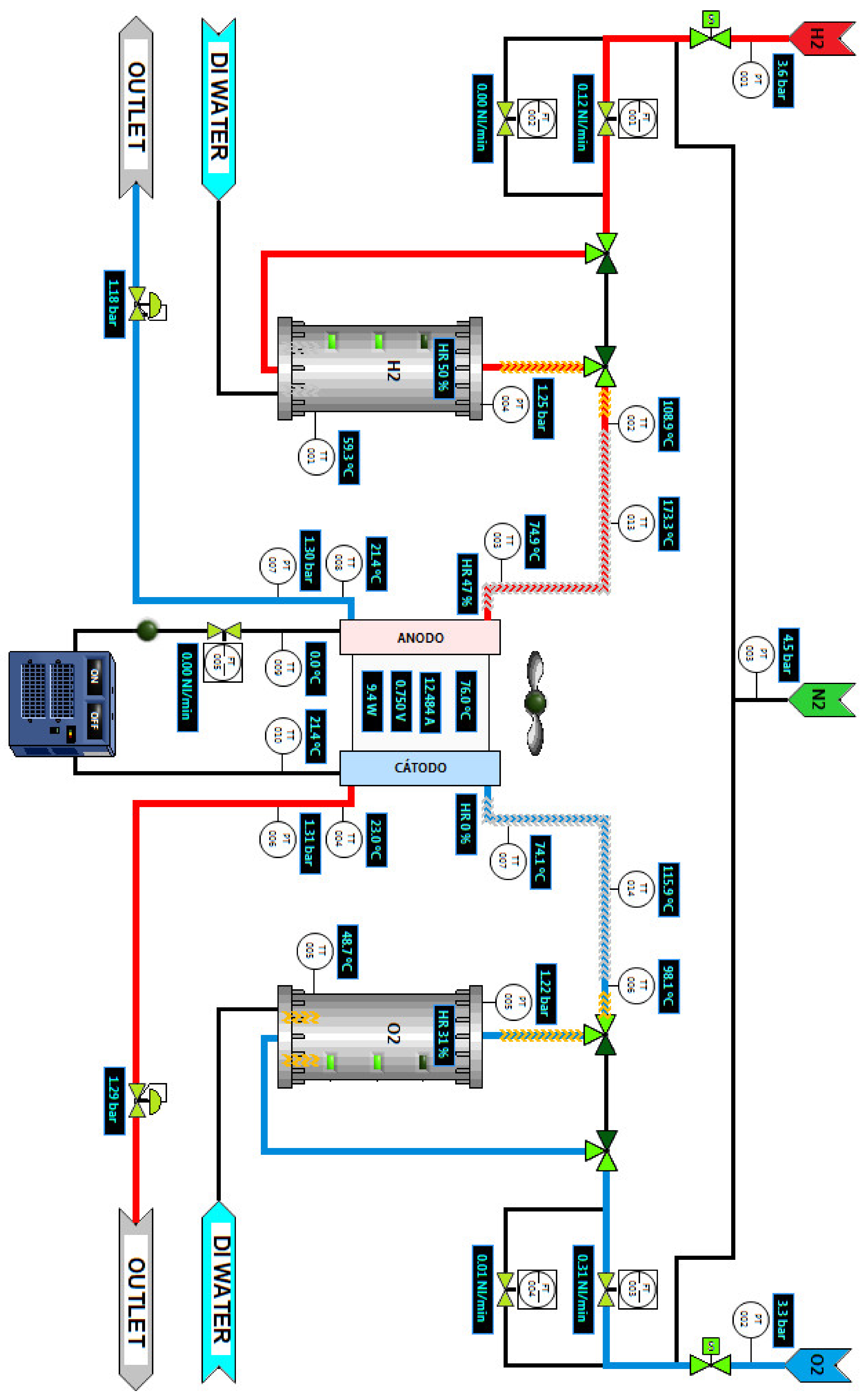
| Column ID | Original Variable Name | Translated Variable Name | Unit | Description |
|---|---|---|---|---|
| 1 | FECHA | Date | dd/mm/yy | Actual date |
| 2 | HORA | Time | hh:mm:ss | Actual time |
| 3 | PT001 | PT001 | bar(a) | Pressure 1 |
| 4 | PT002 | PT002 | bar(a) | Pressure 1 |
| 5 | PT003 | PT003 | bar(a) | Pressure 1 |
| 6 | PT004 | PT004 | bar(a) | Pressure 1 |
| 7 | PT005 | PT005 | bar(a) | Pressure 1 |
| 8 | PT006 | PT006 | bar(a) | Pressure 1 |
| 9 | PT007 | PT007 | bar(a) | Pressure 1 |
| 10 | BP001 | BP001 | bar(a) | Pressure 1 |
| 11 | BP002 | BP002 | bar(a) | Pressure 1 |
| 12 | FT001 | FT001 | Nl/min | H2 flow rate (low flow) 1 |
| 13 | FT002 | FT002 | Nl/min | H2 flow rate (high flow) 1 |
| 14 | FT003 | FT003 | Nl/min | Air flow rate (low flow) 1 |
| 15 | FT004 | FT004 | Nl/min | Air flow rate (high flow) 1 |
| 16 | FT005 | FT005 | Nl/min | Coolant flow rate 1,2 |
| 17 | HT001 | HT001 | % | Relative humidity 1,3 |
| 18 | HT002 | HT002 | % | Relative humidity 1,3 |
| 19 | V001 | V001 | V | Cell voltage |
| 20 | V002 | V002 | V | Cell voltage 2 |
| 21 | V003 | V003 | V | Cell voltage 2 |
| 22 | V004 | V004 | V | Cell voltage 2 |
| 23 | V005 | V005 | V | Cell voltage 2 |
| 24 | V006 | V006 | V | Cell voltage 2 |
| 25 | V007 | V007 | V | Cell voltage 2 |
| 26 | TT001 | TT001 | °C | Temperature 1 |
| 27 | TT002 | TT002 | °C | Temperature 1 |
| 28 | TT003 | TT003 | °C | Temperature 1 |
| 29 | TT004 | TT004 | °C | Temperature 1 |
| 30 | TT005 | TT005 | °C | Temperature 1 |
| 31 | TT006 | TT006 | °C | Temperature 1 |
| 32 | TT007 | TT007 | °C | Temperature 1 |
| 33 | TT008 | TT008 | °C | Temperature 1 |
| 34 | TT009 | TT009 | °C | Temperature 1 |
| 35 | TT010 | TT010 | °C | Temperature 1 |
| 36 | TT011 | TT011 | °C | Temperature 1 |
| 37 | TT012 | TT012 | °C | Temperature 1 |
| 38 | TT013 | TT013 | °C | Temperature 1 |
| 39 | TT014 | TT014 | °C | Temperature 1 |
| 40 | TT015 | TT015 | °C | Temperature 1 |
| 41 | TT016 | TT016 | °C | Temperature 1 |
| 42 | TT017 | TT017 | °C | Temperature 1 |
| 43 | TT018 | TT018 | °C | Temperature 1 |
| 44 | TT019 | TT019 | °C | Temperature 1 |
| 45 | TT020 | TT020 | °C | Temperature 1 |
| 46 | TT021 | TT021 | °C | Temperature 1 |
| 47 | TT022 | TT022 | °C | Temperature 1 |
| 48 | TT023 | TT023 | °C | Temperature 1 |
| 49 | TT024 | TT024 | °C | Temperature 1 |
| 50 | TT025 | TT025 | °C | Temperature 1 |
| 51 | TT026 | TT026 | °C | Temperature 1 |
| 52 | INTENSIDAD | CURRENT | A | Cell current |
© 2020 by the authors. Licensee MDPI, Basel, Switzerland. This article is an open access article distributed under the terms and conditions of the Creative Commons Attribution (CC BY) license (http://creativecommons.org/licenses/by/4.0/).
Share and Cite
Ramírez-Cruzado, A.; Ramírez-Peña, B.; Vélez-García, R.; Iranzo, A.; Guerra, J. Data from Experimental Analysis of the Performance and Load Cycling of a Polymer Electrolyte Membrane Fuel Cell. Data 2020, 5, 47. https://doi.org/10.3390/data5020047
Ramírez-Cruzado A, Ramírez-Peña B, Vélez-García R, Iranzo A, Guerra J. Data from Experimental Analysis of the Performance and Load Cycling of a Polymer Electrolyte Membrane Fuel Cell. Data. 2020; 5(2):47. https://doi.org/10.3390/data5020047
Chicago/Turabian StyleRamírez-Cruzado, Andrea, Blanca Ramírez-Peña, Rosario Vélez-García, Alfredo Iranzo, and José Guerra. 2020. "Data from Experimental Analysis of the Performance and Load Cycling of a Polymer Electrolyte Membrane Fuel Cell" Data 5, no. 2: 47. https://doi.org/10.3390/data5020047
APA StyleRamírez-Cruzado, A., Ramírez-Peña, B., Vélez-García, R., Iranzo, A., & Guerra, J. (2020). Data from Experimental Analysis of the Performance and Load Cycling of a Polymer Electrolyte Membrane Fuel Cell. Data, 5(2), 47. https://doi.org/10.3390/data5020047