Stacked PZT Discs Generate Necessary Power for Bone Healing through Electrical Stimulation in a Composite Spinal Fusion Implant


Abstract
1. Introduction
2. Materials and Methods
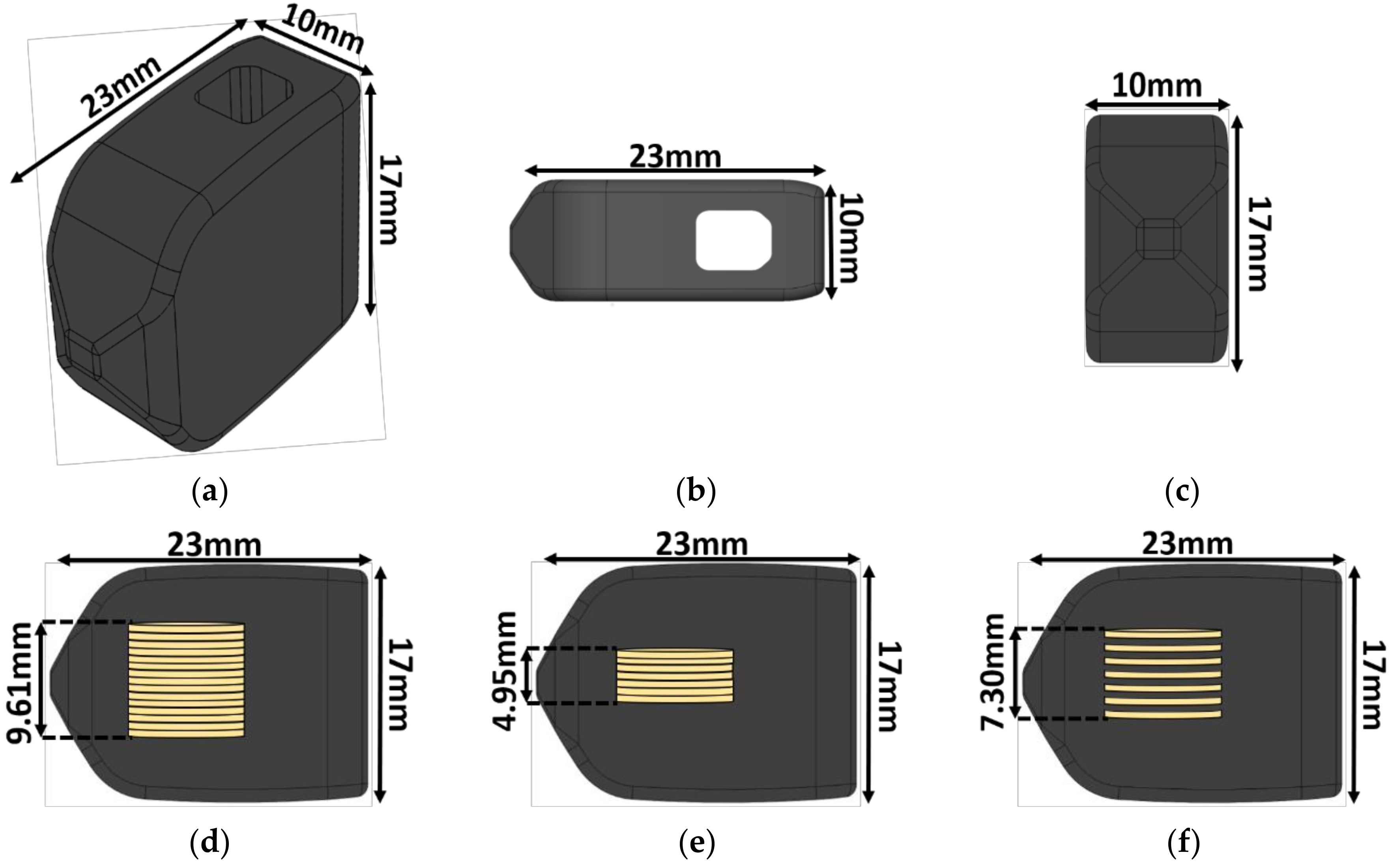
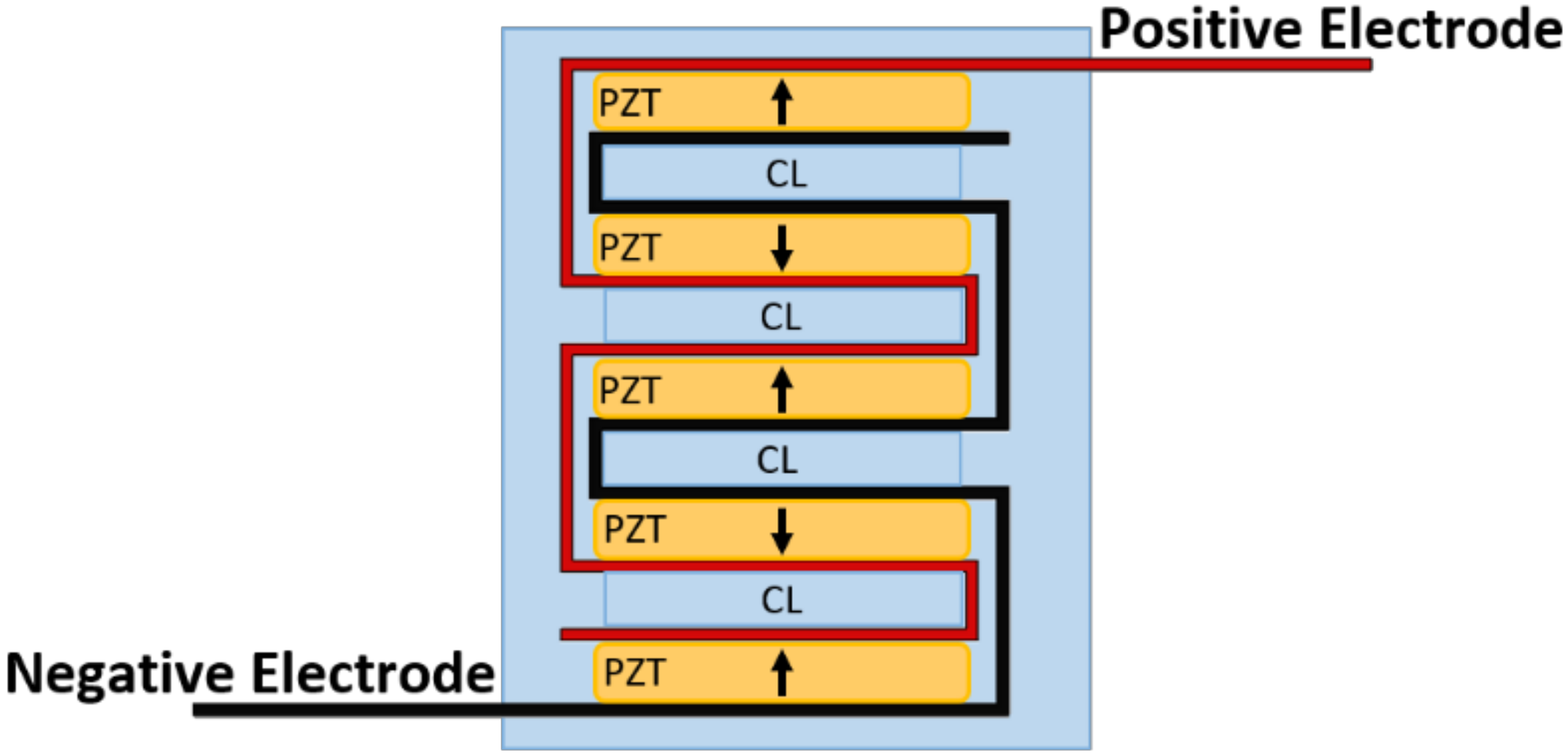
2.1. Implant Design
2.2. Piezoelectric Composite Material Fabrication
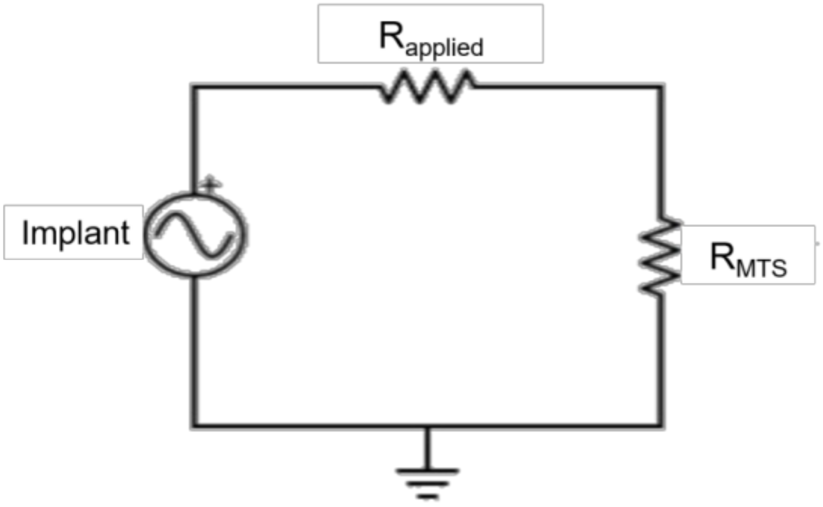
2.3. Electromechanical Testing
2.4. Data Analysis
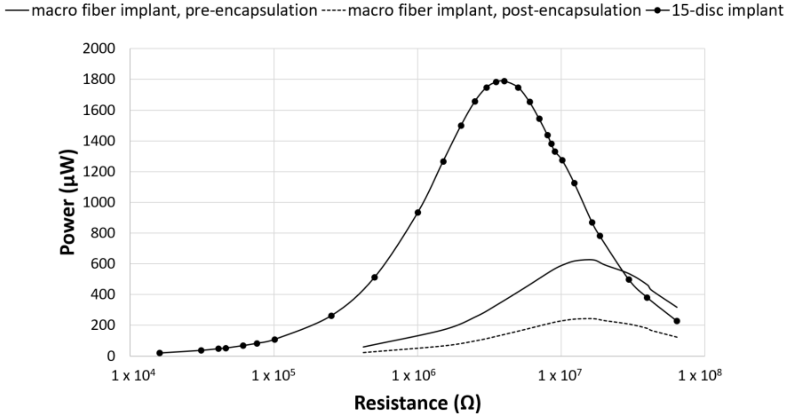
3. Results
4. Discussion
5. Conclusions
Author Contributions
Funding
Acknowledgments
Conflicts of Interest
References
- Waterman, B.R.; Belmont, P.J.; Schoenfeld, A.J. Low back pain in the United States: Incidence and risk factors for presentation in the emergency setting. Spine J. 2012, 12, 63–70. [Google Scholar] [CrossRef] [PubMed]
- Yoshihara, H.; Yoneoka, D. National trends in the surgical treatment for lumbar degenerative disc disease: United States, 2000 to 2009. Spine J. 2015, 15, 265–271. [Google Scholar] [CrossRef] [PubMed]
- iData Research. U.S. Market Report Suite for Spinal Implants and VCF 2017–MedSuite; iData Research: Burnaby, BC, Canada, 2017. [Google Scholar]
- iData Research. U.S. Spinal Implants and VCF Market–2017; iData Research: Burnaby, BC, Canada, 2017. [Google Scholar]
- Cook, S.D.; Patron, L.P.; Christakis, P.M.; Bailey, K.J.; Banta, C.; Glazer, P.A. Direct current stimulation of titanium interbody fusion devices in primates. Spine J. 2004, 4, 300–311. [Google Scholar] [CrossRef] [PubMed]
- Toth, J.M.; Seim, H.B.; Schwardt, J.D.; Humphrey, W.B.; Wallskog, J.A.; Turner, A.S. Direct current electrical stimulation increases the fusion rate of spinal fusion cages. Spine 2000, 25, 2580–2587. [Google Scholar] [CrossRef] [PubMed]
- Berman, D.; Oren, J.H.; Bendo, J.; Spivak, J. The effect of smoking on spinal fusion. Int. J. Spine Surg. 2017, 11. [Google Scholar] [CrossRef] [PubMed]
- Andersen, T.; Christensen, F.B.; Laursen, M.; Høy, K.; Hansen, E.S.; Bünger, C. Smoking as a predictor of negative outcome in lumbar spinal fusion. Spine 2001, 26, 2623–2628. [Google Scholar] [CrossRef] [PubMed]
- Lind, M.; Bünger, C. Factors stimulating bone formation. Eur. Spine J. 2001, 10, S102–S109. [Google Scholar] [CrossRef] [PubMed]
- Carragee, E.J.; Hurwitz, E.L.; Weiner, B.K. A critical review of recombinant human bone morphogenetic protein-2 trials in spinal surgery: Emerging safety concerns and lessons learned. Spine J. 2011, 11, 471–491. [Google Scholar] [CrossRef] [PubMed]
- Victoria, G.; Petrisor, B.; Drew, B.; Dick, D. Bone stimulation for fracture healing: What’s all the fuss? Indian J. Orthop. 2009, 43, 117–120. [Google Scholar] [CrossRef] [PubMed]
- Griffin, M.; Bayat, A. Electrical stimulation in bone healing: Critical analysis by evaluating levels of evidence. Eplasty 2011, 11, e34. [Google Scholar] [PubMed]
- Trumbull, A.; Subramanian, G.; Yildirim-Ayan, E. Mechanoresponsive musculoskeletal tissue differentiation of adipose-derived stem cells. Biomed. Eng. OnLine 2016, 15, 43. [Google Scholar] [CrossRef] [PubMed]
- Fukada, E.; Yasuda, I. On the piezoelectric effect of bone. J. Phys. Soc. Jpn. 1957, 12, 1158–1162. [Google Scholar] [CrossRef]
- Bassett, C.A.L.; Becker, R.O. Generation of electric potentials by bone in response to mechanical stress. Science 1962, 137, 1063–1064. [Google Scholar] [CrossRef] [PubMed]
- Raizman, N.M.; O’Brien, J.R.; Poehling-Monaghan, K.L.; Yu, W.D. Pseudarthrosis of the spine. J. Am. Acad. Orthop. Surg. 2009, 17, 494–503. [Google Scholar] [CrossRef] [PubMed]
- Biomet Spine. Surgical Technique SpF Implantable Spinal Fusion Stimulators; Biomet Spine: Parsippany, NJ, USA, 2017. [Google Scholar]
- Dwyer, A.F.; Wickham, G.G. Direct current stimulation in spinal fusion. Med. J. Aust. 1974, 1, 73–75. [Google Scholar] [PubMed]
- Kane, W.J. Direct current electrical bone growth stimulation for spinal fusion. Spine 1988, 13, 363–365. [Google Scholar] [CrossRef] [PubMed]
- Rogozinski, A.; Rogozinski, C. Efficacy of implanted bone growth stimulation in instrumented lumbosacral spinal fusion. Spine 1996, 21, 2479–2483. [Google Scholar] [CrossRef] [PubMed]
- Tejano, N.A.; Puno, R.; Ignacio, J.M. The use of implantable direct current stimulation in multilevel spinal fusion without instrumentation. A prospective clinical and radiographic evaluation with long-term follow-up. Spine 1996, 21, 1904–1908. [Google Scholar] [CrossRef] [PubMed]
- Kucharzyk, D.W. A controlled prospective outcome study of implantable electrical stimulation with spinal instrumentation in a high-risk spinal fusion population. Spine 1999, 24, 465–468. [Google Scholar] [CrossRef] [PubMed]
- Park, P.; Lau, D.; Brodt, E.D.; Dettori, J.R. Electrical stimulation to enhance spinal fusion: A systematic review. Evid.-Based Spine-Care J. 2014, 5, 87–94. [Google Scholar] [CrossRef] [PubMed]
- Kahanovitz, N. Electrical stimulation of spinal fusion: A scientific and clinical update. Spine J. 2002, 2, 145–150. [Google Scholar] [CrossRef]
- Goetzinger, N.C.; Tobaben, E.J.; Domann, J.P.; Arnold, P.M.; Friis, E.A. Composite piezoelectric spinal fusion implant: Effects of stacked generators. J. Biomed. Mater. Res. B Appl. Biomater. 2016, 104, 158–164. [Google Scholar] [CrossRef] [PubMed]
- Tobaben, E.J.; Goetzinger, N.C.; Domann, J.P.; Barrett-Gonzalez, R.; Arnold, P.M.; Friis, E.A. Stacked macro fiber piezoelectric composite generator for a spinal fusion implant. Smart Mater. Struct. 2015, 24, 017002. [Google Scholar] [CrossRef]
- Friis, E.; Galvis, S.; Arnold, P. DC Stimulation for Spinal Fusion with a Piezoelectric Composite Material Interbody Implant: An Ovine Pilot Study. Available online: http://abstracts.biomaterials.org/data/papers/2015/abstracts/809.pdf (accessed on 20 October 2018).
- Platt, S.R.; Farritor, S.; Haider, H. On low-frequency electric power generation with PZT ceramics. IEEEASME Trans. Mechatron. 2005, 10, 240–252. [Google Scholar] [CrossRef]
- Platt, S.R.; Farritor, S.; Garvin, K.; Haider, H. The use of piezoelectric ceramics for electric power generation within orthopedic implants. IEEEASME Trans. Mechatron. 2005, 10, 455–461. [Google Scholar] [CrossRef]
- Li, H.; Tian, C.; Deng, Z.D. Energy harvesting from low frequency applications using piezoelectric materials. Appl. Phys. Rev. 2014, 1, 041301. [Google Scholar] [CrossRef]
- Mitrovic, M.; Carman, G.P.; Straub, F.K. Response of piezoelectric stack actuators under combined electro-mechanical loading. Int. J. Solids Struct. 2001, 38, 4357–4374. [Google Scholar] [CrossRef]
- Krech, E.; Cadel, E.; Barrett, R.; Friis, E. Effect of compliant layers within piezoelectric composites on power generation providing electrical stimulation in low frequency applications. J. Mech. Behav. Biomed. Mater. 2018, 88, 340–345. [Google Scholar] [CrossRef] [PubMed]
- MatWeb. Quadrant EPP Ketron® 1000 PEEK, Extruded Unfilled Polyetherether Ketone (ASTM Product Data Sheet). Available online: http://www.matweb.com/search/datasheettext.aspx?matguid=53b9159c018544a599a06726922c9b8e (accessed on 20 October 2018).
- Epoxy Technology. EPO-TEK 301 Technical Data Sheet; Epoxy Technology: Billerica, MA, USA, 2016. [Google Scholar]
- Oliveria, T.; Sousa, J. Fatigue behavior of hydroxyapatite coated polyether-ether-ketone derived from dynamic mechanical analysis. Int. J. Fatigue 2017, 108, 1–8. [Google Scholar] [CrossRef]
- Pachi, A.; Ji, T. Frequency and velocity of people walking. Struct. Eng. 2005, 83, 36–40. [Google Scholar]
- Dreischarf, M.; Shirazi-Adl, A.; Arjmand, N.; Rohlmann, A.; Schmidt, H. Estimation of loads on human lumbar spine: A review of in vivo and computational model studies. J. Biomech. 2016, 49, 833–845. [Google Scholar] [CrossRef] [PubMed]
- Cappozzo, A. Compressive loads in the lumbar vertebral column during normal level walking. J. Orthop. Res. Off. Publ. Orthop. Res. Soc. 1984, 1, 292–301. [Google Scholar] [CrossRef] [PubMed]
- Giancoli, D.C. Mastering Physics with E-Book Student Access Kit for Physics for Scientists and Engineers, 4th ed.; Pearson: Upper Saddle River, NJ, USA, 2007; ISBN 978-0-13-199226-9. [Google Scholar]
- Anton, S.R.; Sodano, H.A. A review of power harvesting using piezoelectric materials (2003–2006). Smart Mater. Struct. 2007, 16, R1. [Google Scholar] [CrossRef]
- Tobaben, N.E.; Domann, J.P.; Arnold, P.M.; Friis, E.A. Theoretical model of a piezoelectric composite spinal fusion interbody implant. J. Biomed. Mater. Res. A 2014, 102, 975–981. [Google Scholar] [CrossRef] [PubMed]


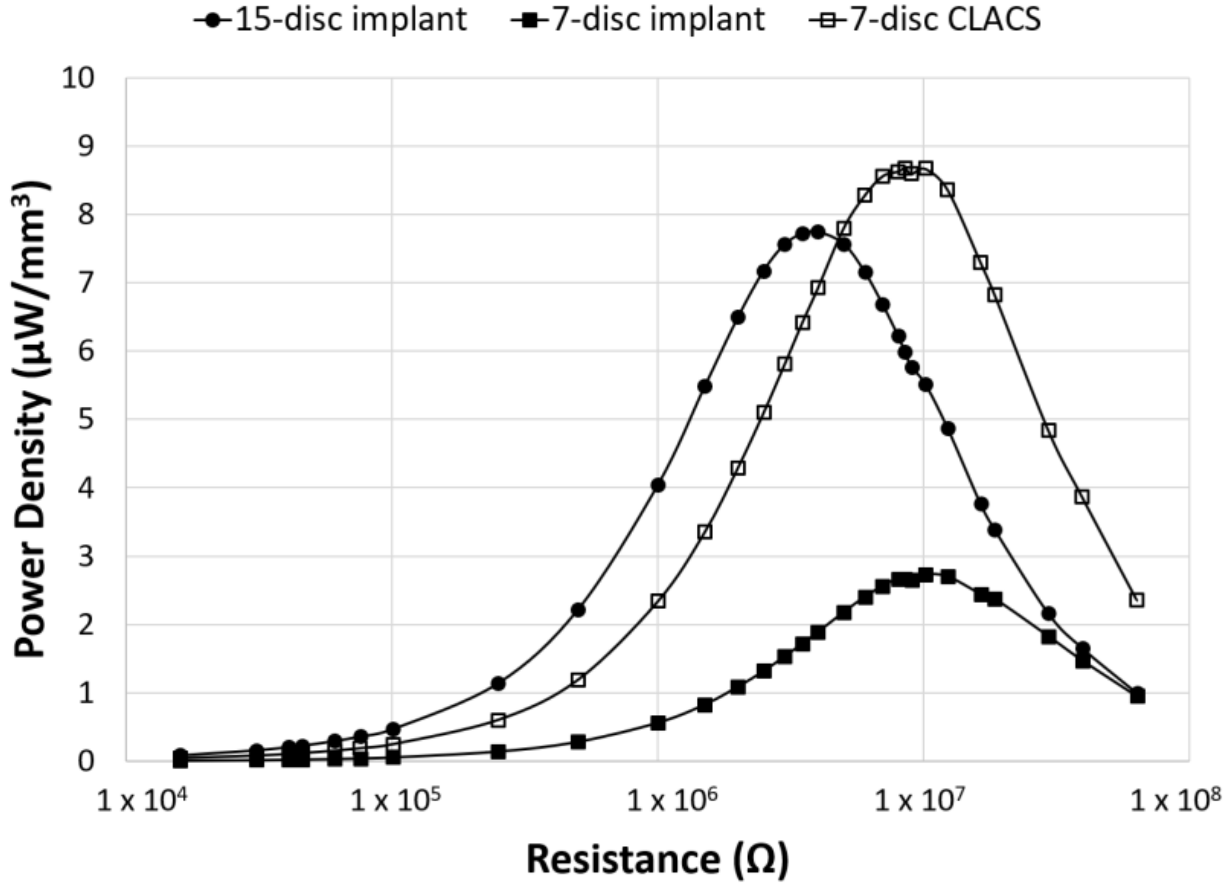
| Implant Type | Average Maximum Power (μW) | Average Voltage at Maximum Power (V) | Applied Resistive Load for Maximum Power (MΩ) |
|---|---|---|---|
| 15-disc insert | 1789 ± 540 | 84 ± 12 | 4 |
| seven-disc insert | 294 ± 90 | 54 ± 9 | 10 |
| seven-disc CLACS insert | 935 ± 261 | 96 ± 14 | 10 |
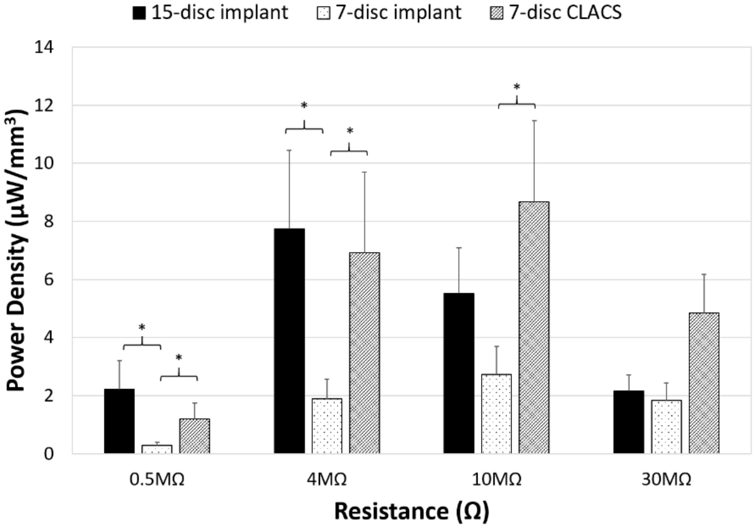
| Implant Type | Average Power at Circuitry Resistance (μW) | Average Voltage at Circuitry Resistance (V) |
|---|---|---|
| 15-disc insert | 500 ± 108 * | 121 ± 13 * |
| seven-disc insert | 197 ± 56 | 75 ± 11 |
| seven-disc CLACS insert | 521 ± 125 * | 123 ± 15 * |
© 2018 by the authors. Licensee MDPI, Basel, Switzerland. This article is an open access article distributed under the terms and conditions of the Creative Commons Attribution (CC BY) license (http://creativecommons.org/licenses/by/4.0/).
Share and Cite
Cadel, E.S.; Krech, E.D.; Arnold, P.M.; Friis, E.A. Stacked PZT Discs Generate Necessary Power for Bone Healing through Electrical Stimulation in a Composite Spinal Fusion Implant. Bioengineering 2018, 5, 90. https://doi.org/10.3390/bioengineering5040090
Cadel ES, Krech ED, Arnold PM, Friis EA. Stacked PZT Discs Generate Necessary Power for Bone Healing through Electrical Stimulation in a Composite Spinal Fusion Implant. Bioengineering. 2018; 5(4):90. https://doi.org/10.3390/bioengineering5040090
Chicago/Turabian StyleCadel, Eileen S., Ember D. Krech, Paul M. Arnold, and Elizabeth A. Friis. 2018. "Stacked PZT Discs Generate Necessary Power for Bone Healing through Electrical Stimulation in a Composite Spinal Fusion Implant" Bioengineering 5, no. 4: 90. https://doi.org/10.3390/bioengineering5040090
APA StyleCadel, E. S., Krech, E. D., Arnold, P. M., & Friis, E. A. (2018). Stacked PZT Discs Generate Necessary Power for Bone Healing through Electrical Stimulation in a Composite Spinal Fusion Implant. Bioengineering, 5(4), 90. https://doi.org/10.3390/bioengineering5040090