Article

Three-Dimensional (3D) Printed Microneedles for Microencapsulated Cell Extrusion

1
Department of Bioengineering, Santa Clara University, Santa Clara, CA 95053-0583, USA
2
SCU Maker Lab, Santa Clara University, Santa Clara, CA 95053-0583, USA
*
Author to whom correspondence should be addressed.
Bioengineering 2018, 5(3), 59; https://doi.org/10.3390/bioengineering5030059
Submission received: 26 June 2018 / Revised: 22 July 2018 / Accepted: 26 July 2018 / Published: 31 July 2018
(This article belongs to the Special Issue Advances in Wound Healing Systems)

Abstract

:
Cell-hydrogel based therapies offer great promise for wound healing. The specific aim of this study was to assess the viability of human hepatocellular carcinoma (HepG2) cells immobilized in atomized alginate capsules (3.5% (w/v) alginate, d = 225 µm ± 24.5 µm) post-extrusion through a three-dimensional (3D) printed methacrylate-based custom hollow microneedle assembly (circular array of 13 conical frusta) fabricated using stereolithography. With a jetting reliability of 80%, the solvent-sterilized device with a root mean square roughness of 158 nm at the extrusion nozzle tip (d = 325 μm) was operated at a flowrate of 12 mL/min. There was no significant difference between the viability of the sheared and control samples for extrusion times of 2 h (p = 0.14, α = 0.05) and 24 h (p = 0.5, α = 0.05) post-atomization. Factoring the increase in extrusion yield from 21.2% to 56.4% attributed to hydrogel bioerosion quantifiable by a loss in resilience from 5470 (J/m3) to 3250 (J/m3), there was no significant difference in percentage relative payload (p = 0.2628, α = 0.05) when extrusion occurred 24 h (12.2 ± 4.9%) when compared to 2 h (9.9 ± 2.8%) post-atomization. Results from this paper highlight the feasibility of encapsulated cell extrusion, specifically protection from shear, through a hollow microneedle assembly reported for the first time in literature.

1. Introduction

Due to the growing need for minimally invasive drug delivery systems and the concern of causing pain and anxiety in patients using a conventional hypodermic needle, localized, and generally pain-free delivery systems for therapeutics, such as resorbable microneedle (RMN) patches and hollow microneedle (HMN) arrays have been developed. Since the growth of the microelectronics industry in the 1990′s and the success of microneedle fabrication and transdermal drug administration in 1998, the development of micromolding techniques for dissolving polymeric microneedle fabrication has enhanced the payload of delivery systems, prompting researchers to expand the repertoire of microneedle therapeutic uses [1]. Transdermal drug delivery studies against complex diseases and vaccination include those of Wang, et al. [2] and Ye., Y. et al. [3], who have loaded hyaluronic acid (HA)-based microneedles with anti-PD1 antibody, glucose oxidase (GOx)-encapsulated dextran nanoparticles, and tumor lysate, melanin, respectively, for the transdermal delivery of antitumor immune response-promoting compounds against melanoma; as well as those of Hu, et al. [4], who loaded HA-based microneedles with insulin and GOx-encapsulated polymeric vesicles, and Lahiji, et al. [5], who developed dissolving microneedles encapsulated with Exendin-4 hormone, against types I and II diabetes. A more comprehensive list of diseases that are treated and therapeutic compounds delivered using MN technology is presented in Table S1 [2,3,4,5,6,7,8,9,10,11,12,13,14,15,16].
Across multiple physiological time scales associated with wound type and wound healing [17] the use of MNs has been investigated in the following areas: (a) antimicrobial wound treatment [18,19,20]; (b) proliferation of endothelial cells [21,22]; (c) scar repair [22,23]; and, (d) treatment of chronic wounds and burns [24,25]. Related cutting edge applications of MNs include biointerfacing [26], wound detection [27], and smart bandages under development combining detection and delivery [28].
Micromolding is the most widely manufacturing method used [12,29]. Other methods include direct photolithography [30], drawing lithography [31], solvent casting [32], mold-based etching [33], and lithography [34], which are all variants that are developed based on the micromolding method of polydimethylsiloxane (PMDS) polymer casting. Numerous biofabrication methods have been devised for RMNs and HMNs a subset of which will be elaborated upon below and presented in Table S2. Ruggiero, et al. [35] have adapted an electro-drawing technique of fabrication, by designing a pattern distribution of integrated metallic micro-heaters that applies an electrohydrodynamic (EHP) force onto polymer solution sessile drops for microneedle shaping. Their setup induces the generation of a uniform electric field, allowing for homogeneous EHP deformation of the drops and careful formation into tapered poly-lactic-glycolic acid (PLGA) RMNs. Johnson, et al. [36] have used an additive manufacturing (AM) method, Continuous Liquid Interface Production (CLIP), to three-dimensional (3D) print dissolving microneedle structures from a computer aided design (CAD) file. The CLIP method they have adapted photopolymerizes the MNs by selectively targeting and solidifying photoreactive resin with ultra-violet (UV) light on a rising platform [36]. In addition, Huh, et al. [37] adapted a Droplet-borne air blowing (DAB) method by first dispensing a polymer drug mixture as a droplet, then contacting, drawing, air-drying, and separating the mixture to form microneedle structures, and similarly, Kim, et al. [38] designed a “Dipping” method to form RMNs in which polymer-coated pillar tips are first coated in a drug of interest, dipped in drug-unmixed solution, then lifted, air-dried, and separated to form microneedle tips. Most recently, Luzuriaga, et al. [39] have adapted a fused deposition modeling (FDM™) based printing method to fabricate RMN structures; this AM method circumvents the need for a clean-room, master template, or mold, which are mandatory for previously used micromolding and lithography-based techniques for fabrication [40,41], and introduces sustainability into microneedle array manufacturing.
Although 3D printing for MNs was first investigated in 2007 by Ovsianikov et al. [42] while using a lithography-based multiphoton polymerization printing method, the ability to print biocompatible and biodegradable materials from conventional 3D printing methods, such as stereolithography (SLA), FDM™, Selective Laser Sintering (SLS), CLIP, and Digital Light Processing (DLP) [43,44,45] has been the focus of numerous studies presented in Table S3. The biofabrication methods have been classified under the AM processes outlined in ISO/ASTM 52900:2015 [46]. SLS and primarily SLA 3D printing have been of interest due to their high resolution and their ability to fabricate solid features smaller than 100 μm, which are ideal for microneedle parameters. However, their disadvantage is that untreated photopolymers used in commercial 3D printers have a lack of biocompatibility and can therefore be toxic for living cell compounds [47,48,49,50]. Therefore, material selection in SLA and SLS 3D printing of MN arrays is key as successfully reported in the following studies: Kang, et al. [51] and Lu, et al. [52] have successfully printed MN arrays pre-loaded with drugs using SLA 3D printing. While, the former study encompassed biofabrication of poly (ethylene glycol) diacrylate (PEGDA) based MN structures embedded in bovine serum albumin, the latter study was based on printing results of poly (propylene fumarate)/diethyl fumarate (PFF) MN arrays that are loaded with dacarbazine drug. In addition to polymers, Gieseke, et al. [53] have SLS-3D printed stainless steel 316l alloy. As previously mentioned, FDM™, followed by etching post-printing used for RMN fabrication [39], its main limitation being the lower resolution when compared to other printing methods, such as SLA and SLS in the absence of post-processing. Other studies, such as Johnson, et al.’s [36] and Miller, et al.’s [54], have also investigated MN fabrication using CLIP and DLP 3D printing methods, respectively, to print biocompatible acrylate-based photopolymer materials, such as Trimethylolpropane Triacrylate and eShell 200 photosensitive acrylate-based biocompatible polymer resin by EnvisionTEC, Inc. (Dearborn, MI, USA).
Due to the breadth of applications, and design considerations for optimal delivery and minimal patient pain, numerous geometries, and array dimensions of MNs have been investigated a subset of which will be elaborated upon. A synopsis is presented in Table S4, with reference to geometries in MN studies presented in Tables S1–S3. MN structures range over the following spatial configurations: Pointed tip with triangular slope [54], conical shape [2,4,14,55,56], cylindrical shape [57], cylindrical body and pointed head [45,52,58], tip-beveled triangular cylinder shape [34], tip-beveled cylinder shape [59,60], pyramidal shape [8,12,61], and tetrahedron-shaped [62]. Based on the studies, these different microneedle shapes and geometries have been shown to breach the stratum corneum layer of human and porcine skin.
Gupta, et al. studied microneedle infusion pressure and pain in human patients while using saline and hollow glass microneedles of variable insertion depth [63]. According to their study, pain is minimized with maximal microneedle insertion depth of 750 μm, delivered medium saline volume of 1 mL, and infusion flow rate 0.3 mL/min. Furthermore, pressures of approximately 500, 1000, and 2000 mmHg were optimal for minimized pain for microneedle insertion depths of 500 and 700 μm. In addition, microneedle tip geometry was investigated in relation to pain; applying microneedles of up to about 700 μm in length, and up to 55 degrees pitch to the skin [64], and using either an array of 10 × 750 μm tall, 75 μm thick, 200 μm wide or 50 × 500 μm tall, 75 μm thick, 200 μm wide microneedles [65] were reported to generally cause minimal pain (no pain or light pain) in patients.
Captured across multiple studies are the Mesenchymal Stem Cells demonstrated effects on cutaneous wound healing and skin regeneration in vitro and in vivo models, by accelerating wound closure, enhancing re-epithelialization, increasing angiogenesis, promoting granulation tissue formation, modulating inflammation, and regulating extracellular matrix remodeling [66,67,68,69,70,71,72]. There are currently 142 registered human clinical trials on stem cells and wound healing worldwide [73]. The major obstacle to clinical translation is stem cell immunogenicity and their reduced survival in vivo [74,75,76,77]. To this effect, polymeric stem cell entrapment strategies, including scaffold surface modifications for transdermal delivery have been devised and tested in preclinical animal wound models [78]. Scaffolding materials include natural, synthetic, and composite polymers and hydrogels with tunable micro/macroporosities, stiffness and bioerosion rates [79,80,81] Amongst nanoporous immuno-protective biomimetic hydrogels, the encapsulation of cells in alginate a linear unbranched polysaccharide containing β-d-mannuronic acid (M) and α-l-guluronic acid (G) residues has been widely applied in preclinical models of drug delivery, wound healing, and tissue regeneration as early as the 1960s [82,83,84,85,86,87].
In a recent British human pilot study to test the safety and efficacy of microneedles for cell delivery ex vivo in patients with vitiligo, melanocyte, keratinocyte, and mixed epidermal cell suspensions were successfully extruded through various types of hollow silicon microneedles ranging from 75–100 μm in bore size and 400–700 μm in depth. All cell types investigated maintained their distinctive phenotype after extrusion through microneedles and at all concentrations after 72 h of testing [88,89].
Combining the advantages of MN-based delivery systems, 3D microenvironments for cell survival and the presence of an immuno-isolation barrier, a custom 3D-printed hollow MN device has been designed to extrude alginate microcapsules into which epithelial cells have been seeded. Human hepatocellular carcinoma (HepG2/ATCC HB-8065), which is a shear sensitive cell line, has been chosen to simulate the behavior of the cocktail of epithelial cells [90,91,92]. To date, there is no study capturing the preclinical biomaterials characterization of HMNs fabricated using stereolithography through which encapsulated mammalian cells have been sheared. Therefore, the specific aim of this paper is to determine whether there is a difference in viability between the extruded encapsulated cells as compared to non-extruded controls.

2. Materials and Methods

2.1. Materials

Human hepatocellular carcinoma (HepG2/ATCC HB-8065) and human glioblastoma (U-87 MG/ATCC HTB-14)™ were obtained from ATCC (Manassas, VA, USA). Dulbecco’s modified Eagle medium (DMEM, Life Technologies 11965) and fetal bovine serum (FBS, Life Technologies 16000) were procured from Life Technologies (Carlsbad, CA, USA). Penicillin-streptomycin (Cellgro, 30–002-CI) and Trypsin-EDTA (Cellgro 25–053-CI) were manufactured by Cellgro (Manassas, VA, USA). All of the reagents that are required for the microencapsulation of cells, including medium viscosity alginate (Sigma A2033 (μ > 2000 cP, Mv = 900–1000 kDa, M/G ratio 1.6), blue dextran dye (Sigma, D4772), as well as reagent grade salts and solvents were purchased from Sigma Aldrich (St. Louis, MO, USA). Proprietary 3D printing photoresins were provided by Formlabs (Summerville, MA, USA).

2.2. Methods

As shown in Figure 1, is the experimental process flow beginning and ending by the 3D printing step and microcapsule extrusion, respectively. SolidWorks was used to design the device that was 3D printed using a Formlabs 2 printer with subsequent post-processing steps. Bonding of the two layers was accomplished using a silicone-based sealant GE Silicone II* Caulk, (General electrics, Boston, MA, USA). The cells were encapsulated in sterilized (3.5% (w/v)) alginate solution. Following encapsulation and crosslinking with 1.5% (w/v) CaCl2, the microcapsules were extruded through the HMN biodevice using a 1 mL syringe.

2.2.1. Device Design Printing and Assembly

Multiple screening runs were conducted prior to determining the nominal MN dimensions, in order to reach a compromise between reported minimization of patient pain [63,64,65], and the resolution limit of the 3D printer. The choice of MN material selection was dictated, in turn, by the highest theoretical resolution of 25 μm achievable using a single photoresin formulation. Hence, prototype replication, biomaterials characterization, extrusion, and viability testing was only conducted for the design discussed in the following section.
(1) Design
The design of the MN device structure was comprised of two main parts: one containing the array of HMNs and the other consisting of a fluid chamber (reservoir).
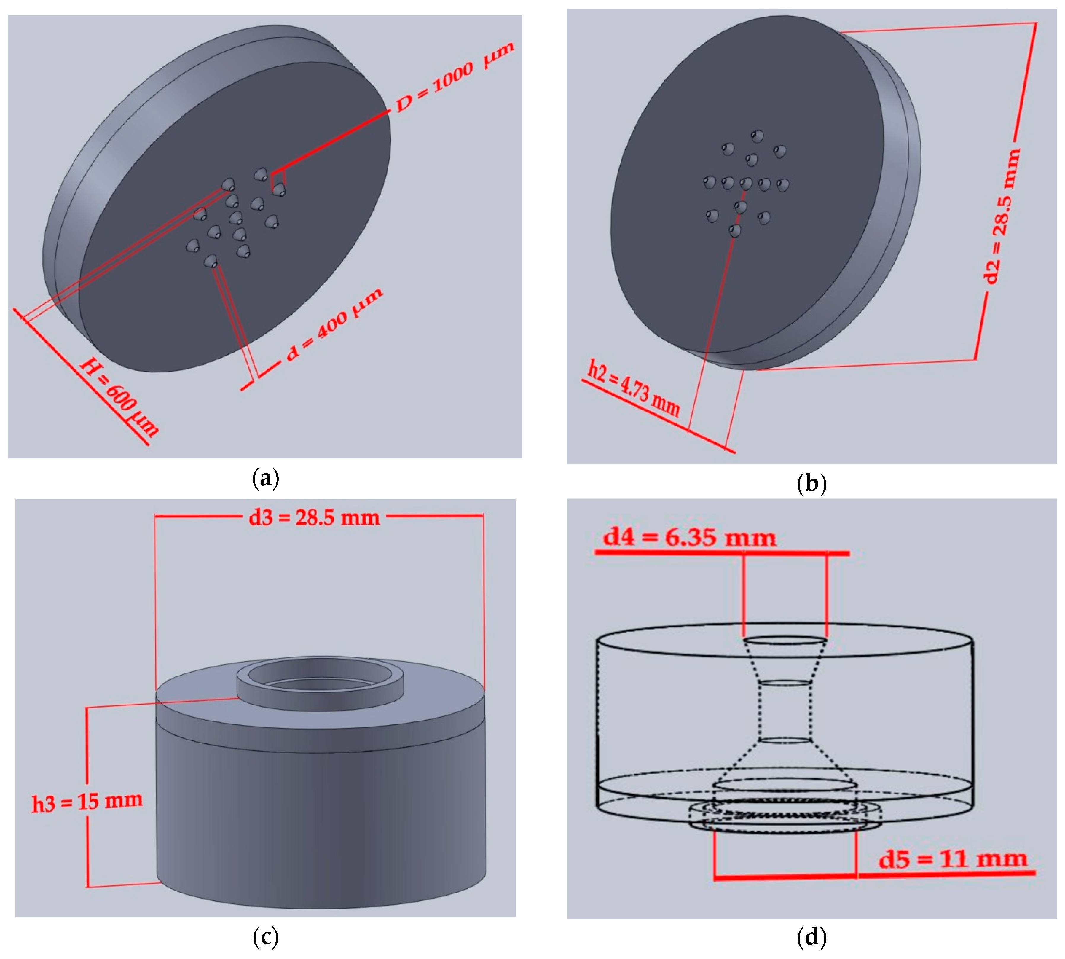
The device prototype was designed using SolidWorks 2017 software (Dassault Systèmes, SolidWorks Corporation, Waltham, MA, USA). Formlabs Clear® photoresin (FLGPCL02) [93] was used to create the top and bottom layers of the device. Reflected below are the nominal dimensions of the biodevice. The bottom layer (Figure 2a,b) included a 28.5 mm diameter (d2) flat disc of height 4.73 mm (h2) with a circular array of 13 microneedles. The dimensions of the cones are: D the diameter (D = 1000 μm); d, the tip diameter (d = 400 μm), H the height (H = 600 μm).
The top layer (Figure 2c) consisted of a large cylindrical outer shape of diameter 28.5 mm (d3) and height of 15 mm (h3). Shown in Figure 2d, is the inner reservoir chamber that is characterized by a volume of 0.5 mL, with a top opening diameter of d4 = 6.35 mm through which the syringe is inserted and bottom opening diameter of d5 = 11 mm.
(2) 3D Printing
3D printing was executed using Formlabs Form 2 printer (Formlabs Inc., 2018, Somerville, MA, USA), operating upon the principle of SLA, with a maximum resolution of 25 μm.
To set the orientation of the device and to generate supports, the preprocessing software, PreForm (Formlabs Inc., v2.16.0, Somerville, MA, USA) was used. This software confirmed the scale of the part, the orientation, the placement of the build tray, as well as the resolution for the photoresin to be used. PreForm enabled mobility of supports, once generated, to ensure that they were not placed at critical feature points of the device. Once these parameters were verified, the device was sent to the printer.
During the printing process, UV light was directed through the window on the bottom side of the printer and selectively cured each cross-section. The microneedle device that is discussed in this paper was orientated so that the microneedle orifices would be perpendicular to the support system. This orientation was possible due to their small dimensions, had the orifices been larger and more susceptible to collapse, they would have to be oriented at an angle to reduce the surface area of each cross-section. Once the parts were successfully printed, supports were removed using standard pliers and the parts were placed in an alcohol bath to ensure quality resolution.
Specifically, parts were placed in isopropyl alcohol (IPA, 70% v/v)), bathed for 20–30 min (10–15 min in tank 1, 10–15 min in tank 2), and then placed in a UV unit for 15 min for post-curing and removal of the uncured resin by leaching. The total processing time for 3D printing and washing the parts took over 5 h, with the ability to print three assemblies per batch.
A total of three devices to be assembled were printed and inspected for dimensional analysis, using a transmission microscope (Olympus CKX53, Center Valley, PA, USA) specifically for the tip radius, r. However, a single assembled part was used throughout experimentation.
(3) Sterilization
Prior to the assembly of the top and bottom parts of the device, the parts were soaked in ethanol (70% v/v) followed by three rinses in sterile DI water. This process will be referred to throughout the manuscript as solvent sterilization.
(4) Assembly
The top and bottom part of the device were mounted in a sterile environment using a silicone-based sealant GE Silicone II* Caulk, (General electrics, Boston, MA, USA). The parts to be sealed were maintained at 50 psi for 30 min.

2.2.2. Surface Topography

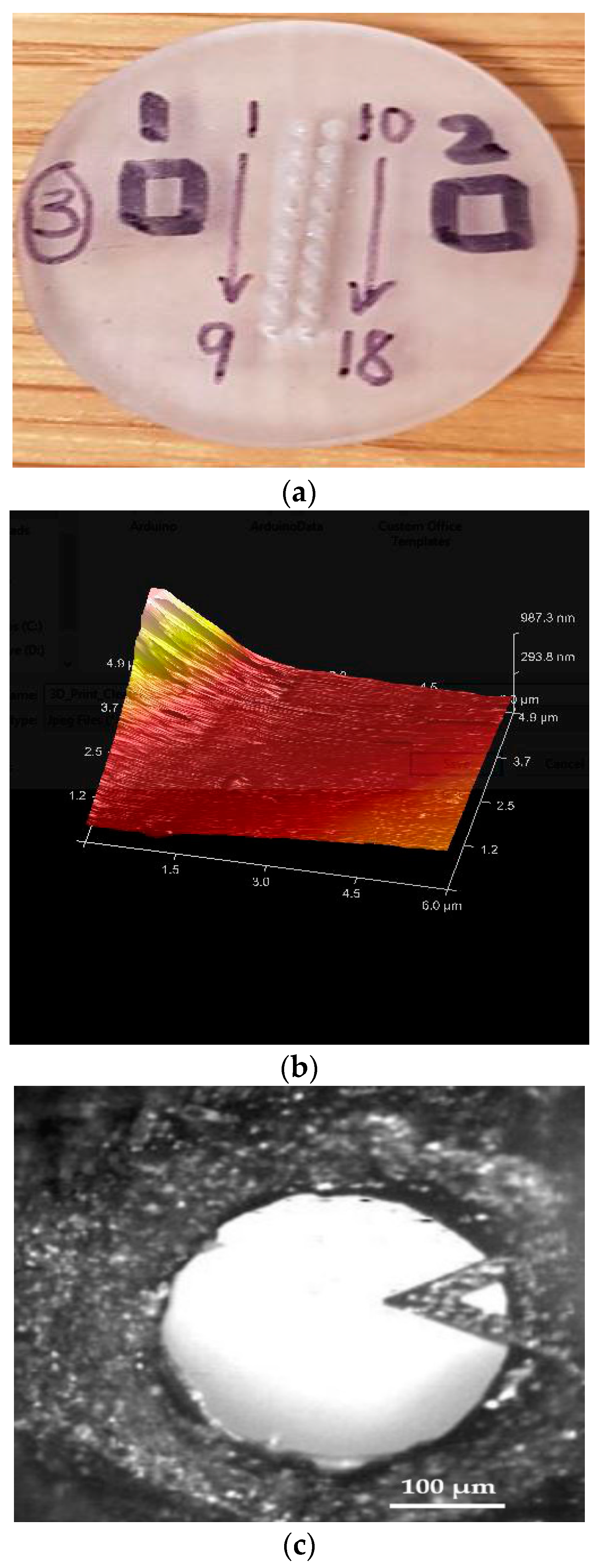
Prior to imaging, the samples were pre-cleaned using an air pump (DOA-P704-AA, Gast, MI, USA) adjusted to 50 psi in order to reduce the risk of particulate contamination in the cleanroom environment. Imaging was performed via a 3100 Dimension atomic force microscopy machine (DAFM-XYZ, Bruker Instruments, Billerica, MA, USA). The Atomic Force Microscopy (AFM) scan was conducted in tapping mode using a Pyrex-Nitride probe (PNP-TR-20, NanoWorld, Neuchâtel, Switzerland) with triangular cantilever (resonant frequency 17 kHz, force constant 0.08 N/m), thickness 500 nm, length 200 μm, tip radius 7–10 nm). Nanoscope v6.13 (Bruker Instruments, Billerica, MA, USA) and Gwyddion v2.3 (Czech Metrology Institute, Brno, Czechoslovakia) were used as qualitative real-time and quantitative image analysis software, respectively. Section analysis and roughness analysis were conducted on the regions of the device that were designed to contact (squares 1 and 2 in Figure 4a) and penetrate the skin (Figure 4c). The scan sizes were 6 μm and 2.8 μm for the flat part and the tip of the microneedle, respectively. Scans were conducted at a frequency of 0.886Hz.
A custom piece comprised of a rectangular array of 18 MNs (Figure 4a) instead of a circular array of 13 MNs (Figure 2a) with identical frusta dimensions being printed for relative ease and accuracy of XY stage positioning when indexing from feature to feature.
It was assumed that the surface topography of this custom part is representative of that of the biodevice.

2.2.3. Mass Flow Capability and Leakage Test

Prior to wet testing conducted at 20 °C, parts were inspected for nozzle occlusion and particulate residue using a transmission microscope (Olympus CKX53, Center Valley, PA, USA). When necessary, nozzle obstruction was alleviated using an air pump (DOA-P704-AA, Gast, MI, USA) adjusted to 50 psi. Flow testing was conducted according to a modified procedure for HMN administration to patients [63].
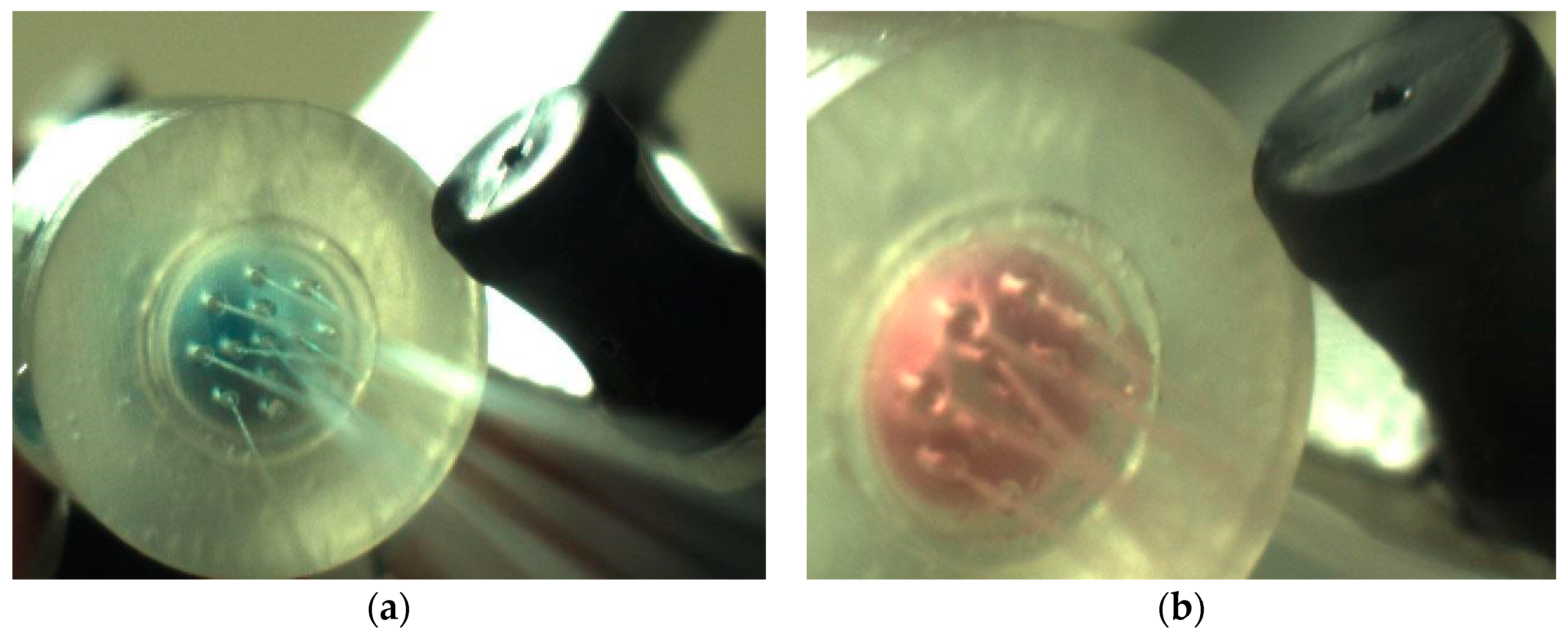
A micropipette (3124000121, Eppendorf, Hamburg, Germany) was used to transfer 0.5 mL of sample into the MN reservoir. Flow testing was conducted at two average flowrates of 1.2 mL/min and 12 mL/min. Blue dextran (single phase) and microcapsules (two phase capsules/media) were used to grade the size of the opening and capture the open/blocked states of the MNs. For the lower flowrate (1.2 mL/min), a syringe pump (NE-1000, New Era Systems, Farmingdale, NY, USA) housing an empty sterile and graduated 1 mL syringe filled with air (Becton Dickinson, Franklin Lakes, NJ, USA) connected to the top of reservoir was used to push the sample through. At the higher flowrate (12 mL/min), the air filled 1 mL syringe was pushed manually and the injection was recorded while using a vision system. Specifically, image capture was conducted at 1 fps using a color camera (1.3 MPX) with a 12.5 mm lens (MA 732, Biomomentum Inc., Montreal, QC, Canada). The flowrate was determined by counting the images until the air-filled syringe was empty.
Percentage jetting reliability was defined as the average number of open nozzles through which two-phase fluid was extruded over 10 runs.

2.2.4. Cell Culture

Two epithelial cell lines (HepG2 and U87-G cells) were maintained following standard mammalian cell culture practices (ATCC, Manassas, VA, USA). The cells were cultured in Dulbecco’s modified Eagle medium (DMEM) (Mediatech, Manassas, VA, USA) and supplemented with 10% fetal bovine serum (FBS) Life Technologies, Carlsbad, CA, USA), sodium pyruvate (Life Technologies), MEM non-essential amino acids (Life Technologies), and 1% penicillin-streptomycin (CellGro, Manassas, VA, USA). They were incubated at 37 °C in a 5% CO2 humidified environment and then grown in 100 mm tissue culture dishes (Greiner, Bio-One, Monroe, CA, USA) to 60–80% confluency. They were subcultured at a 1:4 ratio with 0.25% trypsin (CellGro, Manassas, VA, USA).

2.2.5. Cytotoxicity Screening

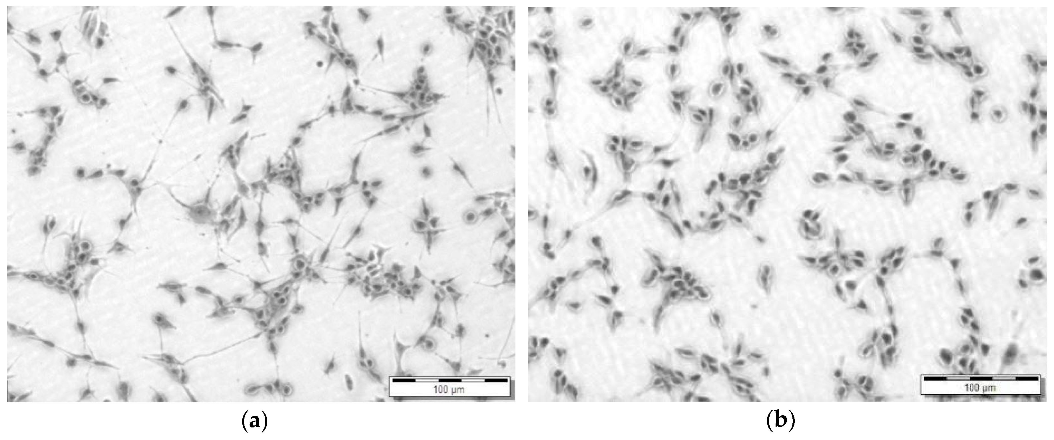
Cytotoxicity screening was conducted according to ISO 10993-5 guidelines [94]. Following solvent sterilization, a 5 mm thick strip of 1 × 3 mm of custom 3D printed part was submerged in cell media containing 3 × 10⁴ cells/mL passaged U87-G cells with a tissue culture polystyrene dish (TCPS) that was prepared with the same cell density as control. Confluency was examined at 24 h using microscopic inspection.
The higher surface area to volume ratio (S/V) of the custom-printed slab used was designed to maximize the chance of bioerosion and leaching of uncured photoresin, As the printed device dimensions decrease, the surface area to volume ratio increases, and thus a higher probability of bioerosion depending on the composition of the polymer resin [95].

2.2.6. Microcapsule Fabrication

Microcapsules were cross-linked by ionotropic gelation, according to previously established methodology [96]. HepG2 cell suspensions in DMEM were mixed with a sterilized 3.5% (w/v) solution of alginate in DMEM to yield a final cell concentration of N0 = 1.9 × 10⁶ cells/mL of alginate. The autoclaved 3.5% (w/v) hydrogel solution was jetted into a 1.5% (w/v) CaCl2 bath for a cross-linking time period of 20 min. The air and liquid flowrates were adjusted to 2.5 L/min and 0.675 mL/min, respectively. The atomizer needle assembly was a concentric 24 G/16G co-axial needle (P/N 100-10-COAXIAL, Rame-Hart, Succasunna, NJ, USA,), through which the sodium alginate and air flowed. The calcified sodium-alginate beads were then washed with 0.9% (w/v) NaCl twice. The alginate-HepG2 beads were subsequently incubated at 37 °C in cell media for either 2 h (Set 1) or 24 h (Set 2) to acclimate to the 3D hydrogel environment prior to further testing.
For the fabrication of empty alginate macrobeads that are used for compression testing, the air flowrate was reduced to 0.5 mL/min, followed by identical cross-linking and wash protocols.

2.2.7. Microcapsule Compression

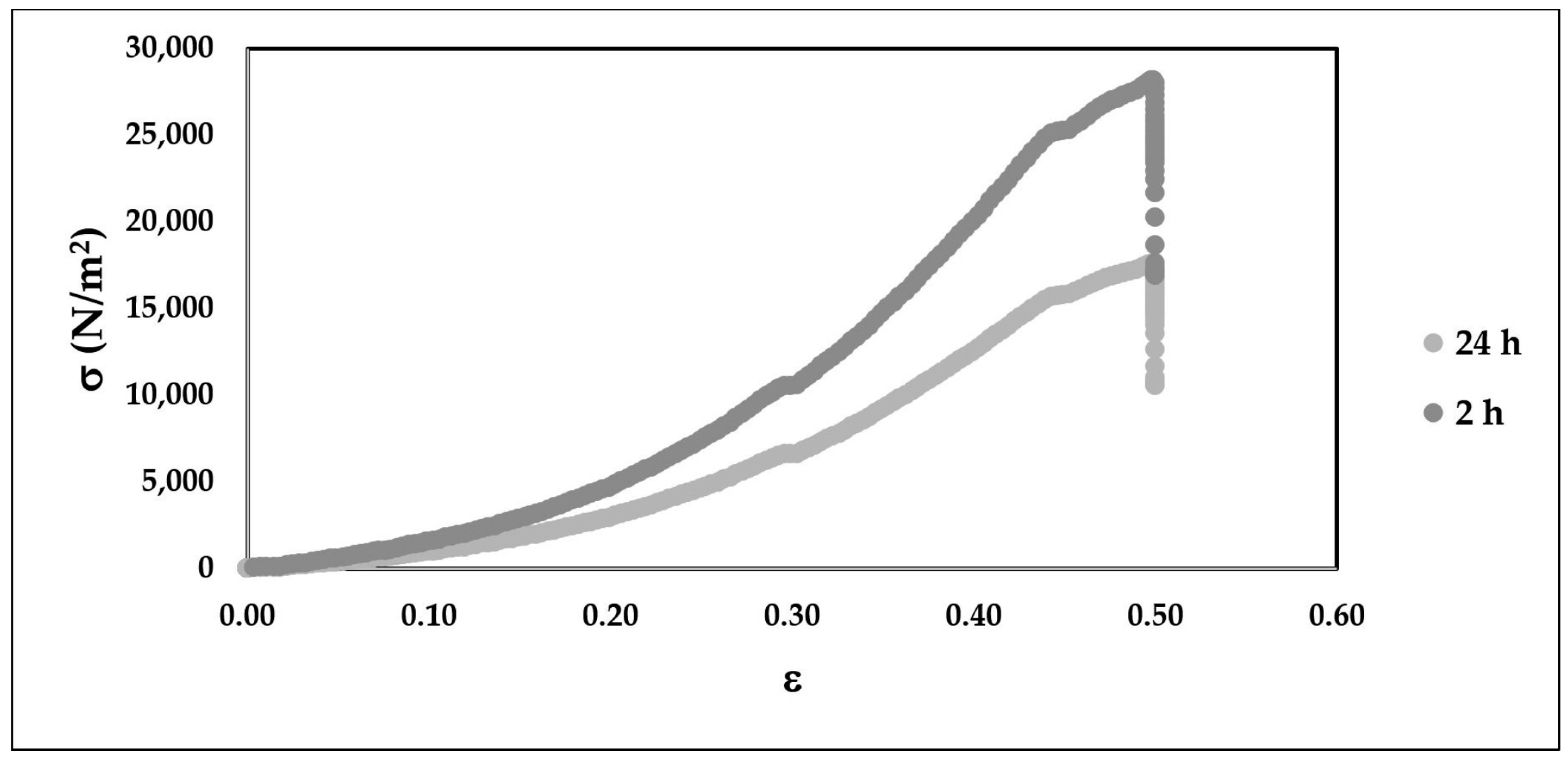
In order to simulate the effect of shear upon ejection from the microneedle tip, 3 mm macrobeads were subjected to surface load tests, followed by Young’s modulus and resilience calculations using Equations (1) and (2), defined by σ, the compressive stress (N/m2), ε the strain, E the Young’s modulus (N/m2), E R the resilience (J/m3), and ε y is the yield strain.
σ = E   ×   ε
E R = 0 ε y σ d ε
A total of 15 closely packed macrocapsules that are embedded in DMEM were subjected to confined compression cycles under a 12.7 mm flat indenter using the Mach I mechanical testing systems (Biomomentum Inc., Montreal, QC, Canada) for correlating the effect of mechanical treatment to the hypothesized loss of elasticity and rupture under the following protocol: 50% compression under a load of 10 kg at a constant strain rate of 1.0 mm/s.
Following, compression macrocapsules were inspected for macro-cracks in the tens of micron range under the microscope.
Macrocapsules were used instead of microcapsules to minimize the artefacts that are associated with sample of adhesion to the indenter.

2.2.8. Optical Measurements

Microcapsule dimensioning for free and immobilized cell visualization pre and post extrusion were conducted using an Olympus CKX53 transmission microscope/camera (Olympus XM10, Center Valley, PA, USA) equipped with the cell Sens Standard imaging software. The sample size for dimension determination and the detection of rupture post extrusion was maintained at 50 capsules. This microscope was also used to measure the printed nozzle radius (r) and for all other visual inspection purposes throughout the study, unless noted otherwise.

2.2.9. Microcapsule Extrusion

1.5 mL of microcapsules pooled from thee atomization batches were mixed and suspended in culture media in preparation for extrusion. Three consecutive 0.5 mL batches were loaded and extruded according to the procedure described in Section 2.2.3. at an average rate of 12 mL/min through the sterilized device from a height of 5 cm. Samples were collected in TCPS dishes and subjected to visual examination under the microscope for rupture.
The percentage extrusion efficiency (Ex) given by Equation (3) was determined by normalizing the mass of 1.5 mL of extruded HepG2 capsules (MEx) to the mass of the same volume of non-extruded HepG2 capsules (MC) used as control.
E x ( % ) = M E x M C × 100

2.2.10. Viability Testing

Responses to extrusion shock were determined as function extrusion delay post encapsulation while using the WST-8 cell proliferation assay (ATCC, Manassas, VA, USA), as per the manufacturer’s instructions. The samples consisting of extruded and non-extruded alginate-HepG2 beads were seeded into 96-well flat bottom plates. WST-8 reagent was added to each well and the samples were incubated in a 37 °C incubator for 5h before the absorbance (A) was measured at 450 nm using a Tecan Infinite 200 PRO spectrophotometer (Durham, NC, USA). Background subtraction was conducted for all measurements using empty beads as controls.

2.2.11. Relative Payload Calculation

Percentage relative payload (RP) given by Equation (4) was obtained by multiplying the background-subtracted absorbance (A’) of the sample by the extrusion efficiency (Ex).
RP ( % ) = A   × E x × 100

2.2.12. Statistical Analysis

Statistical analysis was conducted using MATLAB v2017b (Mathworks, Natick, MA, USA). One sided and two-sided sample t-tests were conducted at a significance level (α) of 0.05.

3. Results

3.1. Device Printing, Sterilization and Assembly

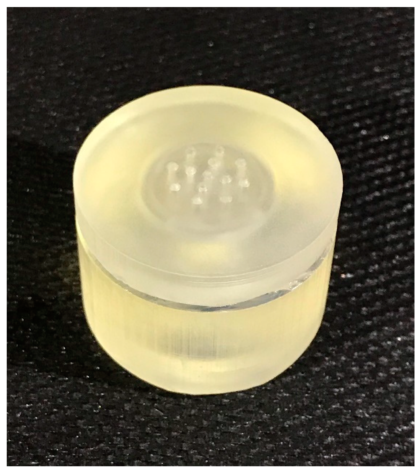
Prior to assembly and sterilization, the array of microneedles was inspected under the microscope for dimensional analysis. The average radius (r) of the microneedle tip was measured to be 162.5 µm ± 20 µm deviating significantly from the design target of 200 µm ± 25 µm (N = 13, p = 0.01, α = 0.05). The assembled sterilized device is presented in Figure 3.

3.2. Surface Topography

The custom-printed part designed for AFM measurements is presented in Figure 4a. The root mean square roughness (RMS) of the flat part was determined from the roughness topography (Figure 4b) generated from the 3D structure of the regions geared towards exposure to the surface of skin was 30 nm. Meanwhile, the RMS of the microneedle tip (Figure 4c) was determined to be 158 nm, as shown in the scan profile (Figure 4d).

3.3. Mass Flow Capability and Leakage Test

No leakage was observed with the sealed device at the lower and upper flowrates of 1.2 mL/min and 12 mL/min, respectively. At the lower flowrate, wicking was observed for both the blue dextran and microcapsules. In addition, particle aggregation resulted in nozzle occlusion and gradual total blockage for the two-phase microcapsule fluid. At the higher flowrate, jetting was observed, as captured in Figure 5, with an associated reliability of 80% over 10 runs for both fluids. Given these observations, capsule extrusion was carried at the higher flowrate of 12 mL/min for the rest of the study.
For the blue dextran, since no nozzle clogs were encountered, jetting was carried out consecutively 10 × 0.5 mL injected batches. For the microcapsules, rinsing with media was necessary after every injected batch.

3.4. Cytotoxicity Screening

As shown in Figure 6, based on epithelial morphology and apparent confluence there is no difference in growth of U87 cells on TCPS and the 3D printed FLGPCL02® photoresin.

3.5. Microcapsule Compression

The resulting nominal stress-strain curves resulting from the 50% compression post incubation at 37 °C in cell culture media based are presented in Figure 7. The yield strain was determined to be at 43% strain. The Young’s moduli for the 2 h and 24 h were 90 kPa and 56 kPa, respectively, equivalent to a resilience loss from 5470 (J/m3) to 3250 (J/m3). No macro-cracks were observed on the surface of the compressed microcapsules for either condition.

3.6. Microcapsule Extrusion

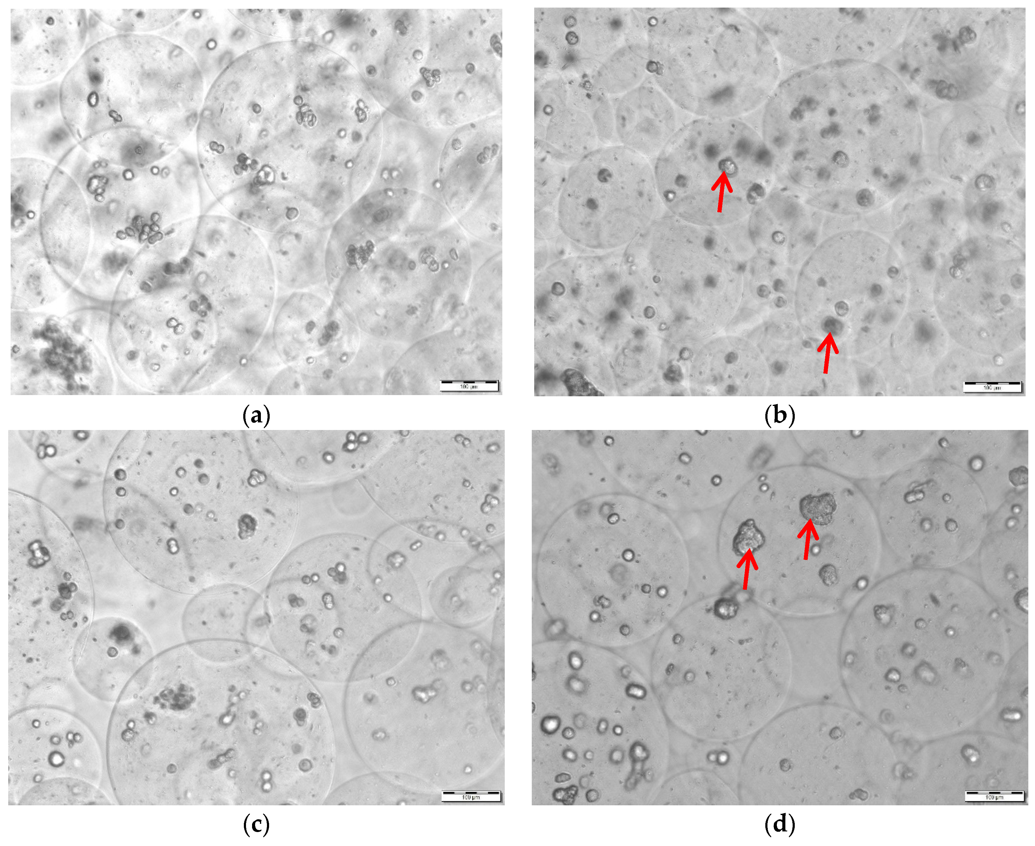
Microcapsules that are characterized by average diameters of 225.1 µm ± 24.5 µm pre-extrusion (Figure 8a,b) were subjected to shear testing through the HMN device. Specifically, two sets of experiments comprised of 3 × 0.5 mL extrusion batches were carried out differing by the delay between cell microencapsulation and injection.
Shown in Figure 8a–d, is a qualitative comparison of growth inside the microcapsules capsules after 2 h (Figure 8a,c) and 24 h (Figure 8b,d) of incubation. Two-hour post microencapsulation, the majority of the HepG2 cells was characterized by a rounded morphology, typical of cells that do not represent moieties for cell adhesion (Figure 8a,c). A day post-incubation, adhesion, darkening of spots, and spheroid formation became apparent (Figure 8b,d).
No rupture was detected in the extruded groups (Figure 8c,d) as compared to control (Figure 8a,b). For Set 1, where extrusion was conducted 2 h after encapsulation (Figure 8c), the extrusion efficiency was 21.2%. Shearing resulted in an uneven distribution of HepG2 capsule size (p = 0.00, α = 0.05), as characterized by an emergence of satellites (d < 100 µm). For Set 2, with a 24 h acclimation time to the 3D environment (Figure 8d) the extrusion efficiency was 54.6%. No statistically significant change in dimension (p = 0.18, α = 0.05) was detected as a result of extrusion, as illustrated in Figure 8d.
Neither swelling nor rupture was observed as a result of incubation (Figure 8a,b).

3.7. Viability Post Extrusion and Relative Payload

To compare the cell viability of extruded and non-extruded (control) HepG2 beads, a mitochondrial assay (WST-8) was conducted immediately post-extrusion. Results are presented in Figure 9a. Based on the results of a one-sided two sample t-test, there was no significant difference in cell viability between the extruded and control groups for Set 1 (p = 0.14, α = 0.05) and Set 2 (p = 0.5, α = 0.05). There was a significant decrease in the viability of the non-extruded control (p = 0.0298, α = 0.05) and extruded cells (p = 0.0175, α = 0.05) after a 24 h incubation period.
Viability in terms of percentage relative payload scaled to incorporate the effect of extrusion is presented in Figure 9b. The effect of extrusion delay was not found to be statistically significant on relative payload (p = 0.2628, α = 0.05).

4. Discussion

There is an 18.75% difference between the specified nozzle (tip) radius (rspecified = d/2 =200 μm) and the dimension of the printed part (rprinted = 162.5 μm) measured by optical microscopy. A well-documented issue of 3D printing is the resulting dimensional accuracy of a printed part. In particular, for printing methods involving layer-by-layer material solidification, such as SLA 3D printing, material shrinkage is induced by the liquid to solid phase change during the building and post-curing procedures [97]. Previously, Finite Element Analysis studies and empirical models have been developed to predict resulting printed shapes and to optimize process parameters, respectively [98], but fell short in accurate prediction due to the high complexity of the model. Although it was determined that UV-light curing provides more uniform shrinkage than thermal post-curing [99], and several studies involving DLP and SLA light-based additive manufacturing of photo-resin material observe such post-print shrinking [100,101,102], modeling, and prediction studies focusing on printed resin shrinkage have only been investigated to a certain extent [98,102]. Among such studies, Huang, et al. have developed a method to model shape volumetric shrinkage for accuracy control in additive manufacturing by plotting shrinkage under polar coordinate representation, and validated the results with SLA-derived, 3D printed SI500 photoresin by EnvisionTEC, Inc. (Dearborn, MI, USA). [98]. Alternatively, experimental volumetric shrinkage can be calculated by comparing resin density before and after it is cured. For example, Huang, et al. developed a photosensitive resin for SLA 3D printing, and measured a shrinking factor of 2.00% post-curing [103]. However, the value is highly variable among SLA printable photosensitive resins, as scan pitch and laser power of the specific 3D printer affects the shrinkage [102]. In the present study, the combined contribution of curing and alcohol washes led to a shrunk nozzle diameter of 325 µm, closer to the maximum 300 μm upper range as proposed in literature and documented to ease patient pain [63,64,65]. Future process optimization efforts will include reducing the specified nozzle diameter (d) and varying the aspect ratio of the frustum in order to achieve a value that is closer to the physical specifications for pain management stated above. Specimens will be subjected to the Izod pendulum impact test to assess the risk of using higher impact ratios [104].
Changing the aspect ratio will, in turn, enable flowrate optimization for therapeutic administration. In this study, the operating flowrate of 12 mL/min associated with reliable jetting of the bolus microcapsule suspension exceeded 40 times the therapeutic value of 0.3 mL/min [63]. Microcapsule administration at lower flowrates led to nozzle blockage induced by aggregation. Colloidal stability can be inferred by surface coating of microcapsules with a polyelectrolyte (modifying the surface charge) and changing the ionic strength of the media [105]. Since media composition is restricted by physiological requirements, physical adsorption of the alginate microcapsules by chitosan or poly-l-lysine routinely used in regenerative medicine is the only tunable variable [106]. A consequence of increased distance between capsules due to electrostatic repulsion may have a lower particle density, resulting in decreased payload. This drawback could be overcome by fabricating smaller alginate structures while using well established methodologies [107]. Another advantage of mitigating aggregation is the elimination of air use for pushing the fluid through the biodevice reservoir, which was proposed as a loading mechanism (Section 2.2.3) to prevent nozzle blockage. Following multifactorial optimization of part design, colloidal stability, and microcapsule miniaturization, with injection using a syringe pump into pig skin, the standard ex vivo model for wound healing will be investigated [108].
The exact composition of the Clear FLGPCL02® methacrylate-based photoresin is proprietary. Distinguishable by clarity, the following is a non-exhaustive list of medical grade resins: dimethacrylate (DMA) [109], polymethylmethacrylate (PMMA), [110] and Methyl methacrylate/acrylonitrile/butadiene styrene (MABS) [111]. Specifically, linked to SLA are methacrylate-based proprietary photoresins [56,57,112] and acrylic-based photoresins [43,54,55]. While methacrylate-based monomers used in bone cements [113], dental fillings are considered to be biocompatible [114], their long-term implantation has been associated with irritancy and cytotoxicity. Cytotoxicity of meth (acrylates) stems from two distinct reactions [115,116]. The first one is the Michael addition, the nucleophilic addition of protein across the double bond of the acrylate function. The second one is the hydrolysis of the ester linkages, of uncured monomer or cured polymer catalyzed by carboxylesterase into carboxylic (acid)s and small molecule alcohols as principal degradation products. While, monomer degradation leads to a local decrease in pH polymer degradation, which leads to inflammation. Apart from bioerosion-related material cytotoxicity, heating of methacrylate-based thermoplastics such as laser cutting processes has been linked to ultrafine particle (UFP) generation [117]. UFP cytotoxicity has been extensively studied for the most commonly used materials in desktop 3D printers Polylactic Acid (PLA) and Acrylonitrile Butadiene Styrene (ABS). UFPs are considered a serious health concern to human health because they deposit in the pulmonary and alveolar regions of the lung [47,118]. Macdonald, et al. used the zebrafish Field Effect Transistor test to investigate the biocompatibility of photopolymers that are used in 3D printers. Leaching of uncured monomers from 3D printed parts was assessed by washing the parts within a large volume of solvents, namely ethanol (70% (v/v) and 99% (v/v)) and IPA (99% (v/v)) under agitation, with 99% ethanol yielding the highest biocompatibility results [47]. Nevertheless, it was found that the photopolymers were highly toxic due to the presence of UFP, nano-sized particles less than 100 nm in diameter, known to be released from ABS materials. PMMA biocompatibility has been proven by results of a recent 72 h cytotoxicity assessment of samples, as determined through growth monitoring, adherence, and morphology of L-929 cells in which a similar ethanol-based protocol was used for sterilization [119]. However, the above-mentioned samples were not photopolymerized, unlike the custom-printed SLA-fabricated piece in the current study. Sources for the hypothetical generation of UFPs in the current biofabrication process would be the post-curing stages and sterilization where the UFPs could be concentrated on the surface. Multiple DI rinses post-solvent sterilization were implemented to reduce the chance of UFP particle seeding. Due to the presence of the immuno-isolation membrane, and the documented molecular weight cutoff of the cross-linked alginate (MWCO) of 68 kDa, equivalent to a Stokes’ radius of 3 nm [120], in the possible event that UFPs were present on the surface of the biodevice, the viability results would not be affected. However, the risk of particulate introduction upon insertion into the patients’ skin needs to be investigated in future studies.
While the preliminary qualitative results of the short term screening (24 h) cytotoxicity presented in Figure 6, suggested an equivalency between U87 cell line proliferation on TCPS and the custom 3D printed Clear FLGPCL02® photoresin, future studies will encompass an IC50 determination (half maximal inhibitory concentration of a substance) [94,121] using the WST-8 assay. Specifically, the following samples that were collected through sequential stages of the study incubated in DMEM will be diluted to multiple concentrations in order to construct the dose-dependent viability curve: (a) post-cured pre-assembled prototype; (b) assembled HMNs post-sterilization; and, (c) post-extruded microcapsules. PMMA surfaces are characterized by a critical surface tension of 37.5 dyn/cm [122] positioned at the lower level threshold for biofouling [123]. Surface roughness measurements that are related to bacterial adhesion research in PMMA-based implants range from 40 nm [124] to 200 nm [125] with a positive correlation between roughness and adhesion. Meanwhile, the newer bioactive bone cements are designed to be porous [126,127]. There is an overlap between the measured RMS range for the custom-printed methacrylate-based slabs (30–158 nm) and the reported biocompatible range (40–200 nm). The HMN parts in the present study were not designed to be porous. Further AFM experimentation is needed to distinguish surface roughness from random pore morphology. In addition, a Zisman plot will be constructed to determine the critical surface tension of the proprietary photoresin.
Entrapment of mammalian cells in alginate-based structures reported using various metrics depend on biofabrication methods, namely electrospraying, microfludic fabrication, in-situ polymerization, and atomization [82,128,129,130]. Use of sodium citrate for capsule core liquefaction by incubating the beads in 0.055 M sodium citrate solution (a Ca2+ chelator) is a standard method for cell recovery [131,132,133,134]. Because of the smaller extrusion volumes from the biodevice, the hydrogel membrane was not subjected to chelation and the viability measurements were based solely on the WST-8 assay dye diffusion through the alginate membrane. Since the Stokes’ radius of the dye is an order of magnitude smaller than the reported 70 kDa MWCO of the membrane [120], diffusion should not theoretically be rate-limiting. Shown in Figure 8a–d is the random positioning of the entrapped HepG2 cells. Due to the stagnant dye layer at the boundary of the membrane, the reaction for the cells in the middle of the capsule may have been diffusion-limited. Incubation times that are higher than 2 h recommended by the manufacturer overcame this limitation, however the accuracy of the assay was compromised by the cross-reactivity of the media. This source of error in viability determination is reflected in the norm of the standard deviations of background-subtracted absorbances shown in Figure 9a, amounting to as high as a third of the average values. There was no significant viability loss as a result of extrusion for day 1 (Set 1) and day 2 (Set 2). However, there was significant loss of viability post 24 h incubation independent of the delay between microencapsulation and extrusion. Spheroid formation that was detected after a day (Figure 8b,d) and diffusion limited transport of oxygen and nutrients due to a stagnant microenvironment may have been a root cause for this decline in viability. These hypotheses will be tested in future long-term studies, using alternate methods of viability detection, namely the live/dead fluorescence-based assays [131,134,135,136]. Furthermore, the WST-8 assay will be revisited after cell recovery by chelation of the cross-linked membrane. Once the cells are free, they may be subjected to proliferation and differentiation protocols to assess the effect of shear through the biodevice. With less noise in viability measurements, initial cell number optimization for delaying the formation of spheroids, as well as the suitability of sterilization while using the standard methods such ethylene oxide and γ-radiation will also be assessed.
Bulk and surface erosion of cross-linked alginate structures occurs in physiological media as a result of chelation and subsequent swelling [137,138]. The major constituent of FBS is bovine serum albumin [139], with a MW of 68 kDa, known to be a cutoff for cross-linked alginate membranes [120]. At constant temperature, equilibrium swelling in media is a balance between osmotic, electrostatic, and elastic forces that are holding the cross-links together [140,141]. No significant swelling was detected as a result of incubation as presented in Figure 8a,b, suggesting that either the concentration of albumin was not high enough to cause an osmotic effect after 24 h, or, the rate of chelation was insignificant for the 3.5% (w/v) alginate membrane.
It could be hypothesized that the bioerosion-driven measured a loss of resilience illustrated in Figure 7 after 24 h of incubation in media was the driving force behind the higher extrusion yield (Ex = 54.6%). For stiffer (E = 90 kPa) microcapsules that were incubated for 2 h in media (Set 1), the HMN array acted as a strict and random filter, as illustrated by the preponderance of satellites in Figure 8c and the extrusion yield of 21.2%. Meanwhile, for more flexible microcapsules (Set 2, E = 54 kPa) that are jetted through the HMNs change in size distribution, as previously stated, was not statistically significant (p = 0.18, α = 0.05). Elasticity of alginate microcapsules is a function of alginate composition (i.e., M/G ratio, presence of collagen), cross-linking time, matrix porosity and strain rate [134,142,143]. Furthermore, the Young’s modulus is inversely correlated to the size of the microspherical constructs assuming that adhesive contact exists between individual particles [144,145]. To that effect, the relative elasticity norms between macrocapsules and microcapsules are translatable, suggesting that it was easier to extrude softer capsules. Across the above-mentioned multifactorial studies the average Young’s modulus for 3 mm alginate beads ranged between 25–35 kPa as compared to 90 kPa obtained in the current study. Sources of discrepancy could be the higher alginate concentration of 3.5% (w/v), a higher cross-linking time of 20 min, a difference in strain rates and load cell ratings. Future parallel macro and micro indentation studies in physiological media should be conducted in DMEM in order to assess the validity of this hypothesis.
No direct comparisons can be drawn between the present study and the recent delivery of epidermal cells through silicon HMNs [88,89] due to the lack of an immuno-isolation membrane and the clinical nature of the latter research.

5. Conclusions

In this bench scale study a custom 3D printed HMN biodevice comprised of a reservoir chamber and an array of conical microneedle (13 conical frusta, d = 400 μm, D = 1000 μm, H = 600 μm) was fabricated using the sustainable low cost method of SLA. The Null hypothesis was accepted since the viability of extruded encapsulated HepG2 cells through the solvent-sterilized device was statistically equivalent to that of non-extruded capsules at the 95% confidence interval. With a RMS value of 158 nm being determined by AFM, the nozzle tip roughness was comparable to PMMA-based dental implants that are associated with cell adhesion. Preliminary qualitative screening cytotoxicity tests that are based on U87 cell adhesion indicated equivalency between the photoresin and TCPS in terms of biocompatibility, the validity of which should be confirmed using dose-dependent quantitative IC50 studies.
This microneedle platform may be customized for delivery of a broad variety of tunable scaffold properties and it should not be limited to alginate. Despite a shrinkage rate of 18.75%, the dimension of the nozzle tip measured to be 325 μm exceeded the geometric specification of <300 μm associated with patient pain minimization [63,64,65]. Using SLA and the proprietary methacrylate-based Formlabs Clear photoresin®, the rate limiting factor will be the improvement of printing resolution, which in turn governs flow optimization and painless administration. In the interim, the possibility of extrusion of cells protected by an immune-isolation membrane through other existing HMNs, expandable into applications of wound healing therapies pivoting on hydrogel cell interactions will be explored.

6. Patent

A provisional US patent (Appl. No.: 62/696410) has been filed as a result of this work.

Supplementary Materials

The following are available online at https://www.mdpi.com/2306-5354/5/3/59/s1, Table S1: Diseases and compounds delivered using MN transdermal delivery, Table S2: MN Manufacturing methods for resorbable (RMN) and hollow (HMN) microneedles, Table S3: 3D printed Methods for MN fabrication, Table S4: MN geometries.

Author Contributions

C.F., R.L., C.H., conceived, designed, performed the device-related experiments and contributed to the data analysis as well as manuscript preparation. H.C. performed the AFM surface characterization experiment. A.M. contributed to the 3D printing optimization of the device. E.B., maintained the cells lines. M.M.-M. conducted the formal analysis, supervised the project and wrote the manuscript.

Funding

The work was supported by the Bannan School of Engineering Senior Design Funds.

Acknowledgments

The authors would like to acknowledge the support of the SCU Center of Nanostructures and the SCU Maker Lab where the prototype surface characterization and 3D printing were conducted, respectively.

Conflicts of Interest

The authors declare no conflict of interest.

Abbreviations

AcronymDefinition
ABSAcrylonitrile Butadiene Styrene
AFMAtomic Force Microscopy
AMAdditive manufacturing
CADComputer-aided design
CLIPContinuous liquid interface production
DABDroplet-borne air blowing
DC-hMN-iSystemDigitally controlled injection system
DHEDihydroergotamine mesylate
DMADimethacrylate
DLPDigital Light Processing
DMEMDulbecco’s Modified Eagle Medium
EHPElectrohydrodynamic processing
FBSFetal Bovine Serum
FDMFused Deposition Modeling
M/GMannuronic acid to Guluronic acid ratio
GENGentamicin
GOxGlucose Oxidase
HAHyaluronic Acid
HMNHollow microneedle
IC50Half maximal inhibitory concentration
MABSMethyl methacrylate/acrylonitrile/butadiene styrene
MN Microneedle
MPPMultiphoton Polymerization
MWCOMolecular Weight Cut Off
NPNanoparticles
PDMSPolydimethylsiloxane
PEGPoly (ethylene glycol)
PEGDAPoly (ethylene glycol) diacrylate
PFFPoly (propylene fumarate)
PLAPolylactic Acid
PLGAPoly-lactic-glycolic acid
PMMAPolymethylmethacrylate
PVPPolyvinylpyrrolidone
PVsPolymeric Vesicles
RMNResorbable microneedle
RMSRoot mean square roughness
S/VSurface area to volume ratio
SLAStereolithography
SLSSelective Laser Sintering
TCPSTissue culture polystyrene
UFPUltrafine particle

References

  1. Henry, S.; Mcallister, D.V.; Allen, M.G.; Prausnitz, M.R. Microfabricated Microneedles: A Novel Approach to Transdermal Drug Delivery. J. Pharm. Sci. 1998, 87, 922–925. [Google Scholar] [CrossRef] [PubMed]
  2. Wang, C.; Ye, Y.; Hochu, G.M.; Sadeghifar, H.; Gu, Z. Enhanced Cancer Immunotherapy by Microneedle Patch-Assisted Delivery of Anti-PD1 Antibody. Nano Lett. 2016, 16, 2334–2340. [Google Scholar] [CrossRef] [PubMed]
  3. Ye, Y.; Wang, C.; Zhang, X.; Hu, Q.; Zhang, Y.; Liu, Q.; Wen, D.; Milligan, J. A Melanin-mediated Cancer Immunotherapy Patch. Sci. Immunol. 2017, 2. [Google Scholar] [CrossRef] [PubMed]
  4. Hu, X.; Yu, J.; Qian, C.; Lu, Y.; Kahkoska, A.R.; Xie, Z.; Jing, X.; Buse, J.B.; Gu, Z. H2O2-Responsive Vesicles Integrated with Transcutaneous Patches for Glucose-Mediated Insulin Delivery. ACS Nano 2017, 11, 613–620. [Google Scholar] [CrossRef] [PubMed]
  5. Lahiji, S.F.; Jang, Y.; Huh, I.; Yang, H.; Jang, M.; Jung, H. Exendin-4-encapsulated dissolving microneedle arrays for efficient treatment of type 2 diabetes. Sci. Rep. 2018, 8, 1170. [Google Scholar] [CrossRef] [PubMed]
  6. Qiu, Y.; Guo, L.; Zhang, S.; Xu, B.; Gao, Y.; Hu, Y.; Hou, J.; Bai, B.; Shen, H.; Mao, P. DNA-based Vaccination Against Hepatitis B Virus Using Dissolving Microneedle Arrays Adjuvanted by Cationic Liposomes and CpG ODN. Drug Deliv. 2015, 1, 1–8. [Google Scholar] [CrossRef] [PubMed]
  7. Esser, E.S.; Romanyuk, A.; Vassilieva, E.V.; Jacob, J.; Prausnitz, M.R.; Compans, R.W.; Skountzou, I. Tetanus Vaccination with a Dissolving Microneedle Patch Confers Protective Immune Responses in Pregnancy. J. Control. Release 2016, 236, 47–56. [Google Scholar] [CrossRef] [PubMed]
  8. Ryu, H.R.; Jeong, H.-R.; Seon-Woo, H.-S.; Kim, J.S.; Lee, S.K.; Kim, H.J.; Baek, J.O.; Park, J.H.; Roh, J.Y. Efficacy of a Bleomycin Microneedle Patch for the Treatment of Warts. Drug Deliv. Transl. Res. 2017, 8, 273–280. [Google Scholar] [CrossRef] [PubMed]
  9. Maaden, K.V.D.; Heuts, J.; Camps, M.; Pontier, M.; Scheltinga, A.T.V.; Jiskoot, W.; Ossendorp, F.; Bouwstra, J. Hollow Microneedle-mediated Micro-injections of a Liposomal HPV E7 43–63 Synthetic Long Peptide Vaccine for Efficient Induction of Cytotoxic and T-helper Responses. J. Control. Release 2018, 269, 347–354. [Google Scholar] [CrossRef] [PubMed]
  10. Bhatnagar, S.; Kumari, P.; Pattarabhiran, S.P.; Venuganti, V.V.K. Zein Microneedles for Localized Delivery of Chemotherapeutic Agents to Treat Breast Cancer: Drug Loading, Release Behavior, and Skin Permeation Studies. AAPS PharmSciTech 2018, 19, 1818–1826. [Google Scholar] [CrossRef] [PubMed]
  11. Ali, A.A.; Mccrudden, C.M.; Mccaffrey, J.; Mcbride, J.W.; Cole, G.; Dunne, N.J.; Robson, T.; Kissenpfennig, A.; Donnelly, R.F.; McCarthy, H.O. DNA Vaccination for Cervical Cancer: A Novel Technology Platform of RALA Mediated Gene Delivery via Polymeric Microneedles. Nanomed. Nanotechnol. Biol. Med. 2017, 13, 921–932. [Google Scholar] [CrossRef] [PubMed]
  12. González-Vázquez, P.; Larrañeta, E.; Mccrudden, M.T.; Jarrahian, C.; Rein-Weston, A.; Quintanar-Solares, M.; Zehrung, D.; McCarthy, H.; Courtenay, A.J.; Donnelly, R.F. Transdermal Delivery of Gentamicin using Dissolving Microneedle Arrays for Potential Treatment of Neonatal Sepsis. J. Control. Release 2017, 265, 30–40. [Google Scholar] [CrossRef] [PubMed]
  13. Yan, Q.; Liu, H.; Cheng, Z.; Xue, Y.; Cheng, Z.; Dai, X.; Shan, W.; Chen, F. Immunotherapeutic Effect of BCG-polysaccharide Nucleic Acid Powder on Mycobacterium Tuberculosis-infected Mice using Microneedle Patches. Drug Deliv. 2017, 24, 1648–1653. [Google Scholar] [CrossRef] [PubMed]
  14. Zhang, Y.; Liu, Q.; Yu, J.; Yu, S.; Wang, J.; Qiang, L.; Gu, Z. Locally Induced Adipose Tissue Browning by Microneedle Patch for Obesity Treatment. ACS Nano 2017, 11, 9223–9230. [Google Scholar] [CrossRef] [PubMed]
  15. Katsumi, H.; Tanaka, Y.; Hitomi, K.; Liu, S.; Quan, Y.-S.; Kamiyama, F.; Sakane, T.; Yamamoto, A. Efficient Transdermal Delivery of Alendronate, a Nitrogen-Containing Bisphosphonate, Using Tip-Loaded Self-Dissolving Microneedle Arrays for the Treatment of Osteoporosis. Pharmaceutics 2017, 9, 29. [Google Scholar] [CrossRef] [PubMed]
  16. Tas, C.; Joyce, J.C.; Nguyen, H.X.; Eangoor, P.; Knaack, J.S.; Banga, A.K.; Prausnitz, M.R. Dihydroergotamine Mesylate-loaded Dissolving Microneedle Patch Made of Polyvinylpyrrolidone for Management of Acute Migraine Therapy. J. Control. Release 2017, 268, 159–165. [Google Scholar] [CrossRef] [PubMed]
  17. Gurtner, G.C.; Werner, S.; Barrandon, Y.; Longaker, M.T. Wound Repair and Regeneration. Nature 2008, 453, 314–321. [Google Scholar] [CrossRef] [PubMed]
  18. Park, S.Y.; Lee, H.U.; Lee, Y.C.; Kim, G.H.; Park, E.C.; Han, S.H.; Lee, J.G.; Choi, S.; Heo, N.S.; Kim, D.L.; et al. Wound healing potential of antibacterial microneedles loaded with green tea extracts. Mater. Sci. Eng. C Mater. Biol. Appl. 2014, 42, 757–762. [Google Scholar] [CrossRef] [PubMed]
  19. Caffarel-Salvador, E.; Kearney, M.C.; Mairs, R.; Gallo, L.; Stewart, S.A.; Brady, A.J.; Donnelly, R.F. Methylene blue-loaded dissolving microneedles: Potential use in photodynamic antimicrobial chemotherapy of infected wounds. Pharmaceutics 2015, 7, 397–412. [Google Scholar] [CrossRef] [PubMed]
  20. Saghazadeh, S.; Rinoldi, C.; Schot, M.; Kashaf, S.S.; Sharif, F.; Jalilian, E.; Nuutila, K.; Giatsidis, G.; Mostafalu, P.; Derakhshandeh, H.; et al. Drug delivery systems and materials for wound healing applications. Adv. Drug Deliv. Rev. 2018, 127, 138–166. [Google Scholar] [CrossRef] [PubMed]
  21. Takada, K.; Ito, Y.; Matsumoto, K.; Sato, Y.; Nishio, M.; Tadano, Y.; Kamei, Y.; Takemura, Y.; Inoue, N.; Akasaka, Y.; et al. Usefulness of basic fibroblast growth factor (bFGF) loaded dissolving microneedles for local therapy of skin wounds. J. Biomater. Nanobiotechnol. 2013, 4, 256–264. [Google Scholar] [CrossRef]
  22. Liebl, H.; Kloth, L.C. Skin Cell Proliferation Stimulated by Microneedles. J. Am. Coll. Clin. Wound Spec. 2012, 4, 2–6. [Google Scholar] [CrossRef] [PubMed] [Green Version]
  23. Yeo, D.C.; Balmayor, E.R.; Schantz, J.T.; Xu, C. Microneedle physical contact as a therapeutic for abnormal scars. Eur. J. Med. Res. 2017, 22, 28. [Google Scholar] [CrossRef] [PubMed]
  24. Omolu, A.; Bailly, M.; Day, R.M. Assessment of solid microneedle rollers to enhance transmembrane delivery of doxycycline and inhibition of MMP activity. Drug Deliv. 2017, 24, 942–951. [Google Scholar] [CrossRef] [PubMed] [Green Version]
  25. Yang, S.Y.; O’Cearbhaill, E.D.; Sisk, G.C.; Park, K.M.; Cho, W.K.; Villiger, M.; Bouma, B.E.; Pomahac, B.; Karp, J.M. A bio-inspired swellable microneedle adhesive for mechanical interlocking with tissue. Nat. Commun. 2013, 4, 1702. [Google Scholar] [CrossRef] [PubMed] [Green Version]
  26. Rajabi, M.; Roxhed, N.; Shafagh, R.Z.; Haraldson, T.; Fischer, A.C.; Wijngaart, W.V.D.; Stemme, G.; Niklaus, F. Flexible and Stretchable Microneedle Patches with Integrated Rigid Stainless Steel Microneedles for Transdermal Biointerfacing. PLoS ONE 2016, 11, e0166330. [Google Scholar] [CrossRef] [PubMed]
  27. Mukerjee, E.V.; Isseroff, R.R.; Nuccitelli, R.; Collins, S.D.; Smith, R.L. Microneedle Array for Measuring Wound Generated Electric Fields. In Proceedings of the 2006 International Conference of the IEEE Engineering in Medicine and Biology Society, New York, NY, USA, 30 August–3 September 2006; Volume 1, pp. 4326–4328. [Google Scholar]
  28. University of Nebraska-Lincoln. Smart Bandages for Early Detection of Infection. Available online: https://ucare.unl.edu/opportunities/smart-bandages-early-detection-infection (accessed on 8 July 2018).
  29. Norman, J.J.; Choi, S.-O.; Tong, N.T.; Aiyar, A.R.; Patel, S.R.; Prausnitz, M.R.; Allen, M.G. Hollow Microneedles for Intradermal Injection Fabricated by Sacrificial Micromolding and Selective Electrodeposition. Biomed. Microdevices 2012, 15, 203–210. [Google Scholar] [CrossRef] [PubMed]
  30. Dardano, P.; Caliò, A.; Palma, V.D.; Bevilacqua, M.F.; Matteo, A.D.; Stefano, L.D. A Photolithographic Approach to Polymeric Microneedles Array Fabrication. Materials 2015, 8, 8661–8673. [Google Scholar] [CrossRef] [PubMed] [Green Version]
  31. Choi, Y.; Lee, S.G.; Jeong, J.H.; Lee, K.M.; Jeong, K.H.; Yang, H.; Lee, S.; Choi, Y.W. Nanostructured Lipid Carrier-loaded Hyaluronic Acid Microneedles for Controlled Dermal Delivery of a Lipophilic Molecule. Int. J. Nanomed. 2013, 1, 289. [Google Scholar] [CrossRef] [PubMed]
  32. Wang, Q.L.; Zhu, D.D.; Liu, X.B.; Chen, B.Z.; Guo, X.D. Microneedles with Controlled Bubble Sizes and Drug Distributions for Efficient Transdermal Drug Delivery. Sci. Rep. 2016, 6, 28755. [Google Scholar] [CrossRef] [PubMed]
  33. Kim, H.; Theogarajan, L.S.; Pennathur, S. A Repeatable and Scalable Fabrication Method for Hollow Silicon Microneedles. J. Micromech. Microeng. 2018, 28, 035007. [Google Scholar] [CrossRef]
  34. Ceyssens, F.; Chaudhri, B.P.; Hoof, C.V.; Puers, R. Fabrication Process for Tall, Sharp, Hollow, High Aspect Ratio Polymer Microneedles on a Platform. J. Micromech. Microeng. 2013, 23, 075023. [Google Scholar] [CrossRef]
  35. Ruggiero, F.; Vecchione, R.; Bhowmick, S.; Coppola, G.; Coppola, S.; Esposito, E.; Letterad, V.; Ferraroc, P.; Nettia, P.A. Electro-drawn Polymer Microneedle Arrays with Controlled Shape and Dimension. Sens. Actuators B Chem. 2018, 255, 1553–1560. [Google Scholar] [CrossRef]
  36. Johnson, A.R.; Caudill, C.L.; Tumbleston, J.R.; Bloomquist, C.J.; Moga, K.A.; Ermoshkin, A.; Shirvanyants, D.; Mecham, S.J.; Luft, J.C.; DeSimone, M.J. Single-Step Fabrication of Computationally Designed Microneedles by Continuous Liquid Interface Production. PLoS ONE 2016, 11, e0162518. [Google Scholar] [CrossRef] [PubMed]
  37. Huh, I.; Kim, S.; Yang, H.; Jang, M.; Kang, G.; Jung, H. Effects of Two Droplet-based Dissolving Microneedle Manufacturing Methods on the Activity of Encapsulated Epidermal Growth Factor and Ascorbic Acid. Eur. J. Pharm. Sci. 2018, 114, 285–292. [Google Scholar] [CrossRef] [PubMed]
  38. Kim, M.; Yang, H.; Kim, S.; Lee, C.; Jung, H. The Troy Microneedle: A Rapidly Separating, Dissolving Microneedle Formed by Cyclic Contact and Drying on the Pillar (CCDP). PLoS ONE 2015, 10, e0136513. [Google Scholar] [CrossRef] [PubMed]
  39. Luzuriaga, M.A.; Berry, D.R.; Reagan, J.C.; Smaldone, R.A.; Gassensmith, J.J. Biodegradable 3D Printed Polymer Microneedles for Transdermal Drug Delivery. Lab Chip 2018, 18, 1223–1230. [Google Scholar] [CrossRef] [PubMed]
  40. Vinayakumar, K.B.; Kulkarni, P.G.; Nayak, M.M.; Dinesh, N.S.; Hegde, G.M.; Ramachandra, S.G.; Rajanna, K. A Hollow Stainless Steel Microneedle Array to Deliver Insulin to a Diabetic Rat. J. Micromech. Microeng. 2016, 26, 065013. [Google Scholar] [CrossRef]
  41. Mansoor, I.; Liu, Y.; Häfeli, U.O.; Stoeber, B. Arrays of Hollow Out-of-Plane Microneedles Made by Metal Electrodeposition onto Solvent Cast Conductive Polymer Structures. J. Micromech. Microeng. 2013, 23, 085011. [Google Scholar] [CrossRef]
  42. Ovsianikov, A.; Chichkov, B.; Mente, P.; Monteiro-Riviere, N.A.; Doraiswamy, A.; Narayan, R.J. Two Photon Polymerization of Polymer? Ceramic Hybrid Materials for Transdermal Drug Delivery. Int. J. Appl. Ceram. Technol. 2007, 4, 22–29. [Google Scholar] [CrossRef]
  43. Boehm, R.D.; Jaipan, P.; Yang, K.-H.; Stewart, T.N.; Narayan, R.J. Microstereolithography-fabricated Microneedles for Fluid Sampling of Histamine-contaminated Tuna. Int. J. Bioprinting 2016, 2. [Google Scholar] [CrossRef]
  44. Lim, S.H.; Ng, J.Y.; Kang, L. Three-dimensional Printing of a Microneedle Array on Personalized Curved Surfaces for Dual-pronged Treatment of Trigger Finger. Biofabrication 2017, 9, 015010. [Google Scholar] [CrossRef] [PubMed]
  45. Faraji Rad, Z.; Nordon, R.; Anthony, C.; Bilston, L.; Prewett, P.; Arns, J.-Y.; Arns, C.; Zhang, L.; Davies, G. High Fidelity Replication of Thermoplastic Microneedles with Open Microfluidic Channels. Microsyst. Nanoeng. 2017, 3, 17034. [Google Scholar] [CrossRef]
  46. ISO/ASTM 52901:2017(en) Additive Manufacturing—General Principles—Requirements for Purchased AM Parts. Available online: https://www.iso.org/obp/ui/#iso:std:iso-astm:52900:ed-1:v1:en in (accessed on 8 July 2018).
  47. Macdonald, N.P.; Zhu, F.; Hall, C.J.; Reboud, J.; Crosier, P.S.; Patton, E.E.; Wlodkowic, D.; Cooper, J.M. Assessment of Biocompatibility of 3D Printed Photopolymers Using Zebrafish Embryo Toxicity Assays. Lab Chip 2016, 16, 291–297. [Google Scholar] [CrossRef] [PubMed]
  48. Oskui, S.M.; Diamante, G.; Liao, C.; Shi, W.; Gan, J.; Schlenk, D.; Grover, W.H. Assessing and Reducing the Toxicity of 3D-Printed Parts. Environ. Sci. Technol. Lett. 2015, 3, 1–6. [Google Scholar] [CrossRef]
  49. Carve, M.; Wlodkowic, D. 3D-Printed Chips: Compatibility of Additive Manufacturing Photopolymeric Substrata with Biological Applications. Micromachines 2018, 9, 91. [Google Scholar] [CrossRef]
  50. Athanasiou, K. Sterilization, Toxicity, Biocompatibility and Clinical Applications of Polylactic Acid/Polyglycolic Acid Copolymers. Biomaterials 1996, 17, 93–102. [Google Scholar] [CrossRef]
  51. Kang, L.; Kochhar, C.; Zou, S. Protein Encapsulation in Polymeric Microneedles by Photolithography. Int. J. Nanomed. 2012, 1, 3143. [Google Scholar] [CrossRef] [PubMed]
  52. Lu, Y.; Mantha, S.N.; Crowder, D.C.; Chinchilla, S.; Shah, K.N.; Yun, Y.H.; Wicker, R.B.; Choi, Ja. Microstereolithography and Characterization of Poly(propylene fumarate)-based Drug-loaded Microneedle Arrays. Biofabrication 2015, 7, 045001. [Google Scholar] [CrossRef] [PubMed]
  53. Gieseke, M.; Senz, V.; Vehse, M.; Fiedler, S.; Irsig, R.; Hustedt, M.; Sternberg, K.; Nölke, C.; Kaierle, S.; Wesling, V.; et al. Additive Manufacturing of Drug Delivery Systems. Biomed. Eng. Biomed. Tech. 2012, 57. [Google Scholar] [CrossRef] [Green Version]
  54. Miller, P.R.; Gittard, S.D.; Edwards, T.L.; Lopez, D.M.; Xiao, X.; Wheeler, D.R.; Monteiro-Riviere, N.A.; Brozik, S.M.; Polsky, R.; Narayan, R.J. Integrated Carbon Fiber Electrodes within Hollow Polymer Microneedles for Transdermal Electrochemical Sensing. Biomicrofluidics 2011, 5, 013415. [Google Scholar] [CrossRef] [PubMed]
  55. Lacan, F.; Coulman, S.A.; Hotston, A.; Petkov, P.; Birchall, J.C. Prototyping Parts with Micro Scale Features Using Additive Manufacturing: Using Microneedles as a Case Study. In Proceedings of the 10th International Conference on Multi-Material Micro Manufacture, San Sebastián, Spain, 8–10 October 2013; Volume 1, pp. 109–346. [Google Scholar] [CrossRef]
  56. Pere, C.P.P.; Economidou, S.N.; Lall, G.; Ziraud, C.; Boateng, J.S.; Alexander, B.D.; Lamproua, D.A.; Douroumis, D. 3D Printed Microneedles for Insulin Skin Delivery. Int. J. Pharm. 2018, 544, 425–432. [Google Scholar] [CrossRef] [PubMed]
  57. Liu, T.-L.; Zahedi, S.; Garling, R.J.; Kralickk, F.; Harris, C.A.; Cheng, M.M.-C. Prosthetic Arachnoid Granulations using 3D Printing Technology. In Proceedings of the IEEE 30th International Conference on Micro Electro Mechanical Systems (MEMS), Las Vegas, NV, USA, 22–26 January 2017. [Google Scholar]
  58. Nagamine, K.; Kubota, J.; Kai, H.; Ono, Y.; Nishizawa, M. An Array of Porous Microneedles for Transdermal Monitoring of Intercellular Swelling. Biomed. Microdevices 2017, 19, 68. [Google Scholar] [CrossRef] [PubMed]
  59. Lee, D.-S.; Li, C.G.; Ihm, C.; Jung, H. A Three-dimensional and Bevel-angled Ultra high Aspect Ratio Microneedle for Minimally Invasive and Painless Blood Sampling. Sens. Actuators B Chem. 2018, 255, 384–390. [Google Scholar] [CrossRef]
  60. Wang, P.-C.; Paik, S.-J.; Kim, J.; Kim, S.-H.; Allen, M.G. Hypodermic Needle-like Hollow Polymer Microneedle Array using UV Lithography into Micromolds. J. Microelectromech. Syst. 2011, 23, 991–998. [Google Scholar] [CrossRef]
  61. Lau, S.; Fei, J.; Liu, H.; Chen, W.; Liu, R. Multilayered Pyramidal Dissolving Microneedle Patches with Flexible Pedestals for Improving Effective Drug Delivery. J. Control. Release 2017, 265, 113–119. [Google Scholar] [CrossRef] [PubMed]
  62. Nguyen, H.X.; Banga, A.K. Enhanced Skin Delivery of Vismodegib by Microneedle Treatment. Drug Deliv. Transl. Res. 2015, 5, 407–423. [Google Scholar] [CrossRef] [PubMed]
  63. Gupta, J.; Park, S.S.; Bondy, B.; Felner, E.I.; Prausnitz, M.R. Infusion Pressure and Pain During Microneedle Injection into Skin of Human Subjects. Biomaterials 2011, 32, 6823–6831. [Google Scholar] [CrossRef] [PubMed]
  64. Gill, H.S.; Denson, D.D.; Burris, B.A.; Prausnitz, M.R. Effect of Microneedle Design on Pain in Human Volunteers. Clin. J. Pain 2008, 24, 585–594. [Google Scholar] [CrossRef] [PubMed] [Green Version]
  65. Gupta, J.; Gill, H.S.; Andrews, S.N.; Prausnitz, M.R. Kinetics of Skin Resealing after Insertion of Microneedles in Human Subjects. J. Control. Release 2011, 154, 148–155. [Google Scholar] [CrossRef] [PubMed]
  66. Sasaki, M.; Abe, R.; Fujita, Y.; Ando, S.; Inokuma, D.; Shimizu, H. Mesenchymal Stem Cells Are Recruited into Wounded Skin and Contribute to Wound Repair by Transdifferentiation into Multiple Skin Cell Type. J. Immunol. 2008, 180, 2581–2587. [Google Scholar] [CrossRef] [PubMed] [Green Version]
  67. Maharlooei, M.K.; Bagheri, M.; Solhjou, Z.; Jahromi, B.M.; Akrami, M.; Rohani, L.; Monabati, A.; Noorafshan, A.; Omrani, G.R. Adipose Tissue Derived Mesenchymal Stem Cell (AD-MSC) Promotes Skin Wound Healing in Diabetic Rats. Diabetes Res. Clin. Pract. 2011, 93, 228–234. [Google Scholar] [CrossRef] [PubMed]
  68. Maxson, S.; Lopez, E.A.; Yoo, D.; Danilkovitch-Miagkova, A.; Leroux, M.A. Concise Review: Role of Mesenchymal Stem Cells in Wound Repair. STEM Cells Transl. Med. 2012, 1, 142–149. [Google Scholar] [CrossRef] [PubMed] [Green Version]
  69. Nuschke, A. Activity of Mesenchymal Stem Cells in Therapies for Chronic Skin Wound Healing. Organogenesis 2013, 10, 29–37. [Google Scholar] [CrossRef] [PubMed]
  70. Rodriguez-Menocal, L.; Shareef, S.; Salgado, M.; Shabbir, A.; Badiavas, E.V. Role of Whole Bone Marrow, Whole Bone Marrow Cultured Cells, and Mesenchymal Stem Cells in Chronic Wound Healing. Stem Cell Res. Ther. 2015, 6, 24. [Google Scholar] [CrossRef] [PubMed]
  71. Motegi, S.-I.; Ishikawa, O. Mesenchymal Stem Cells: The Roles and Functions in Cutaneous Wound Healing and Tumor Growth. J. Dermatol. Sci. 2017, 86, 83–89. [Google Scholar] [CrossRef] [PubMed]
  72. Bryant, S.J.; Vernerey, F.J. Programmable Hydrogels for Cell Encapsulation and Neo-Tissue Growth to Enable Personalized Tissue Engineering. Adv. Healthc. Mater. 2017, 7, 1700605. [Google Scholar] [CrossRef] [PubMed] [Green Version]
  73. ClincalTrials.gov. Available online: https://clinicaltrials.gov/ct2/results?cond=wound+healing&term=stem+cells&cntry=&state=&city=&dist (accessed on 18 June 2018).
  74. Duscher, D.; Barrera, J.; Wong, V.W.; Maan, Z.N.; Whittam, A.J.; Januszyk, M.; Gurtner, G.C. Stem Cells in Wound Healing: The Future of Regenerative Medicine? A Mini-Review. Gerontology 2015, 62, 216–225. [Google Scholar] [CrossRef] [PubMed]
  75. Rosemann, A. Why Regenerative Stem Cell Medicine Progresses Slower Than Expected. J. Cell. Biochem. 2014, 115, 2073–2076. [Google Scholar] [CrossRef] [PubMed] [Green Version]
  76. Kirby, G.T.S.; Mills, S.J.; Cowin, A.J.; Smith, L.E. Stem Cells for Cutaneous Wound Healing. BioMed Res. Int. 2015, 2015, 285869. [Google Scholar] [CrossRef] [PubMed]
  77. Cerqueira, M.T.; Pirraco, R.P.; Marques, A.P. Stem Cells in Skin Wound Healing: Are We There Yet? Adv. Wound Care 2016, 5, 64–75. [Google Scholar] [CrossRef] [PubMed] [Green Version]
  78. Dash, B.; Xu, Z.; Lin, L.; Koo, A.; Ndon, S.; Berthiaume, F.; Dardik, A.; Hsia, H. Stem Cells and Engineered Scaffolds for Regenerative Wound Healing. Bioengineering 2018, 5, 23. [Google Scholar] [CrossRef] [PubMed]
  79. Dickinson, L.E.; Gerecht, S. Engineered Biopolymeric Scaffolds for Chronic Wound Healing. Front. Physiol. 2016, 7, 1–12. [Google Scholar] [CrossRef] [PubMed]
  80. Bakhshayesh, A.R.D.; Annabi, N.; Khalilov, R.; Akbarzadeh, A.; Samiei, M.; Alizadeh, E.; Alizadeh-Ghodsi, M.; Davaran, S.; Montaseri, A. Recent Advances on Biomedical Applications of Scaffolds in Wound Healing and Dermal Tissue Engineering. Artif. Cells Nanomed. Biotechnol. 2017, 46, 691–705. [Google Scholar] [CrossRef] [PubMed]
  81. Han, L.-H.; Conrad, B.; Chung, M.T.; Deveza, L.; Jiang, X.; Wang, A.; Butte, M.J.; Longaker, M.T.; Wan, D.; Yang, F. Microribbon-based Hydrogels Accelerate Stem Cell-based Bone Regeneration in a Mouse Critical-size Cranial. J. Biomed. Mater. Res. Part A 2016, 104, 1321–1331. [Google Scholar] [CrossRef] [PubMed]
  82. Wong, H.; Chang, T. Bioartificial Liver: Implanted Artificial Cells Microencapsulated Living Hepatocytes Increases Survival of Liver Failure Rats. Int. J. Artif. Organs 1986, 9, 335–336. [Google Scholar] [CrossRef] [PubMed]
  83. Wright, B.; Hopkinson, A.; Leyland, M.; Connon, C.J. The Secretome of Alginate-Encapsulated Limbal Epithelial Stem Cells Modulates Corneal Epithelial Cell Proliferation. PLoS ONE 2013, 8, e70860. [Google Scholar] [CrossRef] [PubMed]
  84. Schmitt, A.; Rödel, P.; Anamur, C.; Seeliger, C.; Imhoff, A.B.; Herbst, E.; Vogt, S.; van Griensven, M.; Winter, G.; Engert, J. Calcium Alginate Gels as Stem Cell Matrix—Making Paracrine Stem Cell Activity Available for Enhanced Healing after Surgery. PLoS ONE 2015, 10, e0118937. [Google Scholar] [CrossRef] [PubMed]
  85. Bussche, L.; Harman, R.M.; Syracuse, B.A.; Plante, E.L.; Lu, Y.-C.; Curtis, T.M.; Ma, M.; Van de Walle, G.R. Microencapsulated Equine Mesenchymal Stromal Cells Promote Cutaneous Wound Healing in Vitro. Stem Cell Res. Ther. 2015, 6, 1–15. [Google Scholar] [CrossRef] [PubMed]
  86. Vegas, A.J.; Veiseh, O.; Gürtler, M.; Millman, J.R.; Pagliuca, F.W.; Bader, A.R.; Doloff, J.C.; Li, J.; Chen, M.; Olejnik, K.; et al. Long-term Glycemic Control Using Polymer-encapsulated Human Stem Cell–derived Beta Cells in Immune-competent Mice. Nat. Med. 2016, 22, 306–311. [Google Scholar] [CrossRef] [PubMed]
  87. Cooke, M.E.; Pearson, M.J.; Moakes, R.J.A.; Weston, C.J.; Davis, E.T.; Jones, S.W.; Grover, L.M. Geometric Confinement is Required for Recovery and Maintenance of Chondrocyte Phenotype in Alginate. APL Bioeng. 2017, 1, 016104. [Google Scholar] [CrossRef]
  88. Gualeni, B.; Coulman, S.A.; Shah, D.; Eng, P.F.; Ashraf, H.; Vescovo, P.; Blayney, G.J.; Piveteau, L.-D.; Guy, O.J.; Birchall, J.C.; et al. Minimally invasive and targeted therapeutic cell delivery to the skin using microneedle devices. Br. J. Dermatol. 2018, 178, 731–739. [Google Scholar] [CrossRef] [PubMed]
  89. Boniface, K.; Taieb, A.; Seneschal, A. Cell Delivery Using Microneedle Devices: A New Approach to Treat Depigmenting Disorders. Br. J. Dermatol. 2018, 178, 583–594. [Google Scholar] [CrossRef] [PubMed]
  90. Mitteregger, R.; Vogt, G.; Rossmanith, E.; Falkenhagen, D. Rotary Cell Culture System (RCCS): A New Method for Cultivating Hepatocytes on Microcarriers. Int. J. Artif. Organs 1999, 22, 816–822. [Google Scholar] [CrossRef] [PubMed]
  91. Baudoin, R.; Griscom, L.; Prot, J.M.; Legallais, C.; Leclerc, E. Behavior of HepG2/C3A Cell Cultures in a Microfluidic Bioreactor. Biochem. Eng. J. 2011, 53, 172–181. [Google Scholar] [CrossRef]
  92. Deng, X.; Cao, Y.; Yan, H.; Yang, J.; Xiong, G.; Yao, H.; Qi, C. Enhanced Liver Functions of HepG2 Cells in the Alginate/Xyloglucan Scaffold. Biotechnol. Lett. 2014, 37, 235–240. [Google Scholar] [CrossRef] [PubMed]
  93. CLEAR Photoactive Resin SFS Form. Available online: https://formlabs.com/media/upload/Clear-SDS_u324bsC.pdf (accessed on 19 June 2018).
  94. U.S. Department of Health and Human Services; Food and Drug Administration; Center for Devices and Radiological Health. Use of International Standard ISO 10993-1, “Biological Evaluation of Medical devices—Part 1: Evaluation and Testing within a Risk Management Process”. Available online: https://www.fda.gov/downloads/medicaldevices/deviceregulationandguidance/guidancedocuments/ucm348890.pdf (accessed on 19 June 2018).
  95. Treiser, M.; Abramson, S.; Langer, R.; Kohn, J. Biomaterials Science, An Introduction to Materials in Medicine, 3rd ed.; Ratner, B.D., Hoffman, A.S., Schoen, F.J., Lemons, J.E., Eds.; Elsevier: Waltham, MA, USA, 2013; Chapter 1.2.6; p. 179. [Google Scholar]
  96. Mobed-Miremadi, M.; Asi, B.; Parasseril, J.; Wong, E.; Tat, M.; Shan, Y. Comparative Diffusivity Measurements for Alginate-based Atomized and Inkjet-Bioprinted Artificial Cells using Fluorescence Microscopy. Artif. Cells Nanomed. Biotechnol. 2012, 41, 196–201. [Google Scholar] [CrossRef] [PubMed]
  97. Wang, W.; Cheah, C.; Fuh, J.; Lu, L. Influence of Process Parameters on Stereolithography Part Shrinkage. Mater. Des. 1996, 17, 205–213. [Google Scholar] [CrossRef]
  98. Huang, Q.; Zhang, J.; Sabbaghi, A.; Dasgupta, T. Optimal Offline Compensation of Shape Shrinkage for Three-dimensional Printing Processes. IIE Trans. 2014, 47, 431–441. [Google Scholar] [CrossRef]
  99. Karalekas, D.; Aggelopoulos, A. Study of Shrinkage Strains in a Stereolithography Cured Acrylic Photopolymer Resin. J. Mater. Process. Technol. 2003, 136, 146–150. [Google Scholar] [CrossRef]
  100. Wallace, J.; Wang, M.O.; Thompson, P.; Busso, M.; Belle, V.; Mammoser, N.; Kim, K.; Fisher, J.P.; Siblani, A.; Xu, Y.; et al. Validating Continuous Digital Light Processing (cDLP) Additive Manufacturing Accuracy and Tissue Engineering Utility of a Dye-initiator Package. Biofabrication 2014, 6, 015003. [Google Scholar] [CrossRef] [PubMed]
  101. Karrer, P.; Corbel, S.; Andre, J.C.; Lougnot, D.J. Shrinkage Effects in Photopolymerizable Resins Containing Filling Agents: Application to Stereophotolithography. J. Polym. Sci. Part A Polym. Chem. 1992, 30, 2715–2723. [Google Scholar] [CrossRef]
  102. Vitale, A.; Cabral, J. Frontal Conversion and Uniformity in 3D Printing by Photopolymerisation. Materials 2016, 9, 760. [Google Scholar] [CrossRef] [PubMed]
  103. Huang, B.; Du, Z.; Yong, T.; Han, W. Preparation of a Novel Hybrid Type Photosensitive Resin for Stereolithography in 3D Printing and Testing on the Accuracy of the Fabricated Parts. J. Wuhan Univ. Technol. Mater. Sci. Ed. 2017, 32, 726–732. [Google Scholar] [CrossRef]
  104. ASTM. ASTM D256-10e1, Standard Test Methods for Determining the Izod Pendulum Impact Resistance of Plastics. Available online: https://www.astm.org (accessed on 8 July 2018).
  105. Harrison, R.G.; Todd, P.W.; Rudge, S.R.; Petrides, D. Bioseparations Science and Engineering, 1st ed.; Oxford University Press: Oxford, UK, 2002; ISBN 0195123409. [Google Scholar]
  106. Prakash, S. Artificial Cells, Cell Engineering and Therapy; Prakash, S., Ed.; Woodhead Publishing: Cambridge, UK, 2007; ISBN 9781845690366. [Google Scholar]
  107. Mobed-Miremadi, M. High-Throughput Methods for Miniaturization of Implantable Artificial Cells. In Selected Topics in Nanomedicine; Chang, T.M.S., Ed.; World Scientific Publishing: Singapore, 2013; pp. 411–427. ISBN 9789814472852. [Google Scholar]
  108. Seaton, M.; Hocking, A.; Gibran, N.S. Porcine Models of Cutaneous Wound Healing. ILAR J. 2015, 56, 127–138. [Google Scholar] [CrossRef] [PubMed] [Green Version]
  109. Ligon, S.C.; Liska, R.; Stampfl, J.; Gurr, M.; Mulhaupt, R. Polymers for 3D Printing and Customized Additive Manufacturing. Chem. Rev. 2017, 117, 10212–10290. [Google Scholar] [CrossRef] [PubMed]
  110. Tappa, K.; Jammalamadaka, U. Novel Biomaterials Used in Medical 3D Printing Techniques. J. Funct. Biomater. 2018, 9, 17. [Google Scholar] [CrossRef] [PubMed]
  111. Xcentric Mold & Engineering. Injection Molding Material Considerations for the Medical Industry. Available online: https://www.xcentricmold.com/2018/06/18/material-considerations-for-the-medical-industry-utilizing-injection-molding/ (accessed on 8 July 8 2018).
  112. Kundu, A.; Ausaf, T.; Rajaraman, S. 3D Printing, Ink Casting and Micromachined Lamination (3D PICLμM): A Makerspace Approach to the Fabrication of Biological Microdevices. Micromachines 2018, 9, 85. [Google Scholar] [CrossRef]
  113. Jager, M.; Wilke, A. Comprehensive biocompatibility testing of a new PMMA-hA bone cement versus conventional PMMA cement in vitro. Biomater. Sci. Polym. Ed. 2003, 14, 1283–1298. [Google Scholar] [CrossRef]
  114. Frazer, R.Q.; Byron, R.T.; Osborne, P.B.; West, K.P. PMMA: An essential material in medicine and dentistry. J. Long-Term Eff. Med. Implants 2005, 15, 629–639. [Google Scholar] [CrossRef] [PubMed]
  115. Husar, B.; Hatzenbichler, M. Photopolymerization-based additive manufacturing for the development of 3D porous scaffolds. In Biomaterials for Bone Regeneration: Novel Techniques and Applications, 1st ed.; Dubruel, P., Van Vlierberght, S., Eds.; Woodhead Publishing: Cambridge, UK, 2014; pp. 149–198. ISBN 9780857098047. [Google Scholar]
  116. Cheng, W.; Wu, D.; Liu, Y. Michael Addition Polymerization of Trifunctional Amine and Acrylic Monomer: A Versatile Platform for Development of Biomaterials. Biomacromolecules 2016, 17, 3115–3126. [Google Scholar] [CrossRef] [PubMed]
  117. Herrick, D.; Klein, R. Emerging Health and Safety Issues in Makerspaces. In Proceedings of the 1st International Symposium on Academic Makerspaces, Cambridge, MA, USA, 13–16 November 2016; pp. 100–103. [Google Scholar]
  118. Azimi, P.; Zhao, D.; Pouzet, C.; Crain, N.E.; Stephens, B. Emissions of Ultrafine Particles and Volatile Organic Compounds from Commercially Available Desktop Three-Dimensional Printers with Multiple Filaments. Environ. Sci. Technol. 2016, 50, 1260–1268. [Google Scholar] [CrossRef] [PubMed]
  119. Linan, L.Z.; Lima, N.M.N.; Benatti, C.; Xavier, M.; Rodrigues, A.A.; Manenti, F.; Jardini, A.; Filho, R.M.; Gilioli, R. Cytotoxicity Assessment of a Poly(methyl methacrylate) Synthesized for the Direct Fabrication of Bone Tissues. Braz. Arch. Biol. Technol. 2018, 61. [Google Scholar] [CrossRef]
  120. Simpliciano, C.; Clark, L.; Asi, B.; Chu, N.; Mercado, M.; Diaz, S.; Goedert, M.; Mobed-Miremadi, M. Cross-Linked Alginate Film Pore Size Determination Using Atomic Force Microscopy and Validation Using Diffusivity Determinations. J. Surf. Eng. Mater. Adv. Technol. 2013, 3, 1–12. [Google Scholar] [CrossRef]
  121. International Standard ISO Specification 10993-5 Biological evaluation of medical Devices. In Part 5: Tests for In Vitro Cytotoxicity, 3rd ed.; International Organization for Standardization: Geneva, Switzerland, 2009.
  122. AccuDyneTest. Available online: https://www.accudynetest.com/polytable_03.html?sortby=contact_angle (accessed on 8 July 2018).
  123. Baier, R.E. Surface behavior of biomaterials: The theta surface for biocompatibility. J. Mater. Sci. Mater. Med. 2006, 17, 1057–1062. [Google Scholar] [CrossRef]
  124. Buergers, R.; Rosentritt, M.; Handel, G. Bacterial adhesion of Streptococcus mutans to provisional fixed prosthodontic material. J. Prosthet. Dent. 2007, 98, 461–469. [Google Scholar] [CrossRef]
  125. Bollen, C.M.; Lambrechts, P.; Quirynen, M. Comparison of surface roughness of oral hard materials to the threshold surface roughness for bacterial plaque retention: A review of the literature. Dent. Mater. 1997, 13, 258–269. [Google Scholar] [CrossRef]
  126. He, Q.; Chen, H.; Huang, L.; Dong, J.; Guo, D.; Mao, M.; Lei, W. Porous Surface Modified Bioactive Bone Cement for Enhanced Bone Bonding. PLoS ONE 2012, 7, e42525. [Google Scholar] [CrossRef] [PubMed]
  127. Dall’Oca, C.; Maluta, T.; Cavani, F.; Morbioli, G.P.; Bernardi, P.; Sbarbati, A.; Magnan, B. The Biocompatibility of Porous vs Non-Porous Bone Cements: A New Methodological Approach. Eur. J. Histochem. 2014, 58, 2255. [Google Scholar] [CrossRef] [PubMed]
  128. Xie, J.; Wang, C.-H. Electrospray in the dripping mode for cell microencapsulation. J. Colloid Interface Sci. 2007, 312, 247–255. [Google Scholar] [CrossRef] [PubMed]
  129. Håti, A.G.; Bassett, D.C.; Ribe, J.M.; Sikorski, P.; Weitz, D.A.; Stokke, B.T. Versatile, cell and chip friendly method to gel alginate in microfluidic devices. Lab Chip 2016, 16, 3718–3727. [Google Scholar] [CrossRef] [PubMed] [Green Version]
  130. Yang, J.; Li, J.; Wang, X.; Li, X.; Kawazoe, N.; Chen, G. Single mammalian cell encapsulation by in situ polymerization. J. Mater. Chem. B 2016, 47, 7662–7668. [Google Scholar] [CrossRef]
  131. Jing, D.; Parikh, A.; Tzanakakis, E.S. Cardiac Cell Generation from Encapsulated Embryonic Stem Cells in Static and Scalable Culture Systems. Cell Transplant. 2010, 19, 1397–1412. [Google Scholar] [CrossRef] [PubMed] [Green Version]
  132. Zhang, W.; He, X. Encapsulation of Living Cells in Small (~100 μm) Alginate Microcapsules by Electrostatic Spraying: A Parametric Study. ASME. J. Biomech. Eng. 2009, 131. [Google Scholar] [CrossRef] [PubMed]
  133. Wilson, J.L.; Najia, M.A.; Saeed, R.; McDevitt, T.C. Alginate Encapsulation Parameters Influence the Differentiation of Microencapsulated Embryonic Stem Cell Aggregates. Biotechnol. Bioeng. 2014, 111, 618–631. [Google Scholar] [CrossRef] [PubMed]
  134. Gryshkov, O.; Pogozhykh, D.; Hofmann, N.; Pogozhykh, O.; Mueller, T.; Glasmacher, B. Encapsulating Non-Human Primate Multipotent Stromal Cells in Alginate via High Voltage for Cell-Based Therapies and Cryopreservation. PLoS ONE 2014, 9, e0107911. [Google Scholar] [CrossRef] [PubMed] [Green Version]
  135. Ouyang, L.; Yao, R.; Chen, X.i.; Na, J.; Sun, W. 3D printing of HEK 293FT cell-laden hydrogel into macroporous constructs with high cell viability and normal biological functions. Biofabrication 2015, 7, 015010. [Google Scholar] [CrossRef] [PubMed]
  136. Lu, J.; Zhang, X.; Li, J.; Yu, L.; Chen, E.; Zhu, D.; Zhang, Y.; Li, L. A New Fluidized Bed Bioreactor Based on Diversion-Type Microcapsule Suspension for Bioartificial Liver Systems. PLoS ONE 2016, 11, e0147376. [Google Scholar] [CrossRef] [PubMed]
  137. Malafaya, P.B.; Silva, G.A.; Reis, R.L. Natural–origin Polymers as Carriers and Scaffolds for Biomolecules and Cell Delivery in Tissue Engineering Applications. Adv. Drug Deliv. Rev. 2007, 59, 207–233. [Google Scholar] [CrossRef] [PubMed] [Green Version]
  138. Duque, R.; Shan, Y.; Joya, M.; Ravichandran, N.; Asi, B.; Mobed-Miremadi, M.; Mulrooney, S.; McNeil, M.; Prakash, S. Effect of artificial cell miniaturization on urea degradation by immobilized E. coli DH5α (pKAU17). Artif. Cells Nanomed. Biotechnol. 2018, 1–10. [Google Scholar] [CrossRef] [PubMed]
  139. Zheng, X.; Baker, H.; Hancock, W.S.; Fawaz, F.; McCaman, M.; Pungor, E., Jr. Proteomic Analysis for the Assessment of Different Lots of Fetal Bovine Serum as a Raw Material for Cell Culture. Part IV. Application of Proteomics to the manufacture of biological drugs. Biotechnol. Prog. 2006, 22, 1294–1300. [Google Scholar] [CrossRef] [PubMed]
  140. Peppas, N.A. Physiologically Responsive Hydrogels. J. Bioact. Compat. Polym. 1991, 6, 241–246. [Google Scholar] [CrossRef]
  141. Denton, A.R.; Tang, Q. Counterion-Induced Swelling of Ionic Microgels. J. Chem. Phys. 2016, 145, 164901. [Google Scholar] [CrossRef] [PubMed]
  142. Hwang, Y.S.; Cho, J.; Tay, F.; Heng, J.Y.; Ho, R.; Kazarian, S.G.; Williams, D.R.; Boccaccini, A.R.; Polak, J.M.; Mantalaris, A. The use of murine embryonic stem cells, alginate encapsulation, and rotary microgravity bioreactor in bone tissue engineering. Biomaterials 2009, 30, 499–507. [Google Scholar] [CrossRef] [PubMed]
  143. Chan, E.S.; Lim, T.; Voo, W.; Ravindra, P.; Tey, B.T.; Zhang, Z. Effect of formulation of alginate beads on their mechanical behavior and stiffness. Particuology 2011, 9, 228–234. [Google Scholar] [CrossRef]
  144. Briscoe, B.J.; Liu, K.K.; Williams, D.R. Adhesive Contact Deformation of a Single Microelastomeric Sphere. J. Colloid Interface Sci. 1998, 200, 256–264. [Google Scholar] [CrossRef]
  145. Yeatts, A.B.; Gordon, C.N.; Fisher, J.P. Formation of an Aggregated Alginate Construct in a Tubular Perfusion System. Tissue Eng. Part C Methods 2011, 17, 1171–1178. [Google Scholar] [CrossRef] [PubMed]
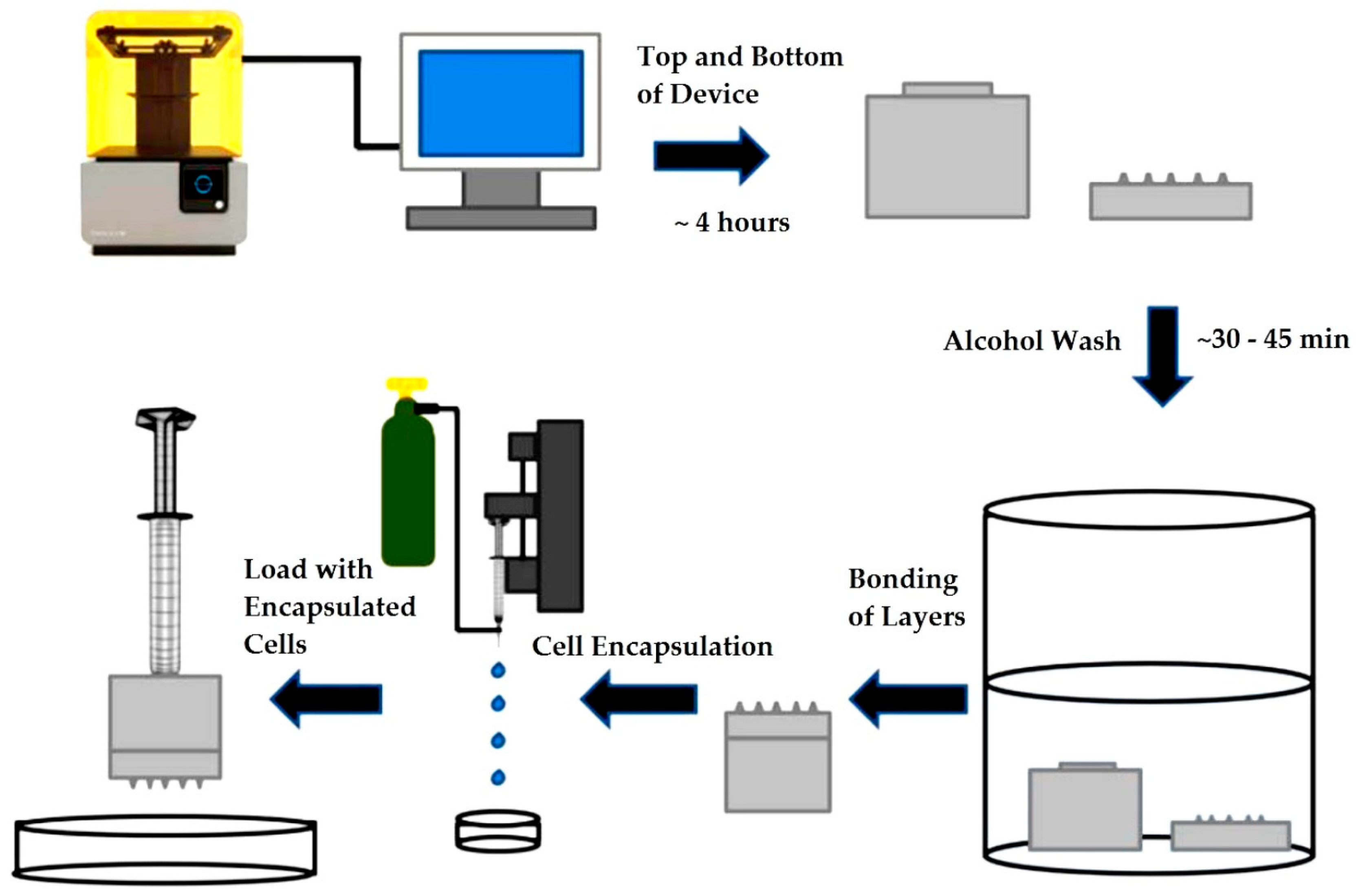
Figure 1. Experimental process flow steps of device fabrication, cell encapsulation, and microcapsule extrusion.
Bioengineering 05 00059 g001
Figure 2. SolidWorks drawings of the printed device with corresponding dimensioning. (a) Circular array of 13 hollow microneedles; (b) bottom layer of device; (c) top layer of device consisting of a large cylindrical outer shape; and, (d) Side view of device rotated 180° with respect to Figure 2c illustrating the reservoir chamber.
Bioengineering 05 00059 g002
Figure 3. Three-dimensional (3D) printed hollow microneedle (HMN) device facing upwards.
Bioengineering 05 00059 g003
Figure 4. Atomic Force Microscopy (AFM) measurements: (a) Labeled custom-printed part designed for surface roughness measurements; (b) 3D structure of the regions geared towards exposure to skin surface utilized for RMS determination; (c) Optical Image of microneedle tip region analyzed during scan; and, (d) Sample AFM section analysis of microneedle tip corresponding to Figure 4c. Scale bar indicates 100 μm.
Bioengineering 05 00059 g004aBioengineering 05 00059 g004b
Figure 5. Flow testing of HMNs at 12 mL/min. (a) Single phase fluid blue dextran dye; and, (b): Two phase fluid microcapsules containing cells in Dulbecco’s modified Eagle medium (DMEM) media.
Bioengineering 05 00059 g005
Figure 6. Short term Cytotoxicity Testing; (a) Control U87 cells after 24 h on TCPS; and, (b) U87 cells incubated on a 5 mm thick strip of 1 mm × 3 mm of custom 3D printed FLGPCL02® photoresin at 24 h. Scale bars indicate 100 μm.
Bioengineering 05 00059 g006
Figure 7. Nominal stress-strain curve for compression testing of macrocapsules 2 h and 24 h post incubation in cell media fir 50% compression at a constant strain rate of 1.0 mm/s.
Bioengineering 05 00059 g007
Figure 8. Encapsulation of HepG2 cells within alginate microcapsules. (a) 3.5% (w/v) alginate capsules 2 h post-fabrication (Set 1, control); (b) 3.5% (w/v) alginate capsules at 24 h post-fabrication (Set 2, control); (c) 3.5% (w/v) alginate extruded capsules 2 h post-fabrication (Set 1); and, (d) 3.5% (w/v) alginate capsules extruded 24 h post-fabrication (Set 2). Scale bar indicates 100µm.Red arrows represent spheroid formation.
Bioengineering 05 00059 g008
Figure 9. Comparative viability expressed in terms of background-subtracted absorbance units and percentage relative payload for extrusion times 2 h (Set 1) and 24 h (Set 2) post-encapsulation. (a) Statistical equivalence of extruded and control (Set 1, p = 0.14, α = 0.05; Set 2, p = 0.5, α = 0.05) and statistically significant decrease in viability form 2 h to 24 h (Control, p = 0.0298, α =0.05; Extruded, p= 0.0175, α = 0.05). (b) Statistical equivalence of percentage relative payload (2 h, RP= 9.9 ± 2.8%; 24 h, RP= 12.2 ± 4.9%, p = 0.2628, α = 0.05).
Bioengineering 05 00059 g009