

3D Printed Piezoelectric BaTiO3/Polyhydroxybutyrate Nanocomposite Scaffolds for Bone Tissue Engineering
 , ,
, ,  ,
,  ,
,  ,
,  and
and
Abstract
1. Introduction
2. Materials and Methods
2.1. Materials
2.2. Nanocomposite Preparation
2.3. Preparation of Samples for Analyses
2.4. Thermal and Thermogravimetric Analyses
2.5. Piezoelectric Characterization of Nanocomposites
2.6. 3D Printing of Nanocomposites
2.7. Tensile and Compression Tests
2.8. Morphological and Porosity Analysis
2.9. Biodegradation Tests
2.10. Statistical Analysis
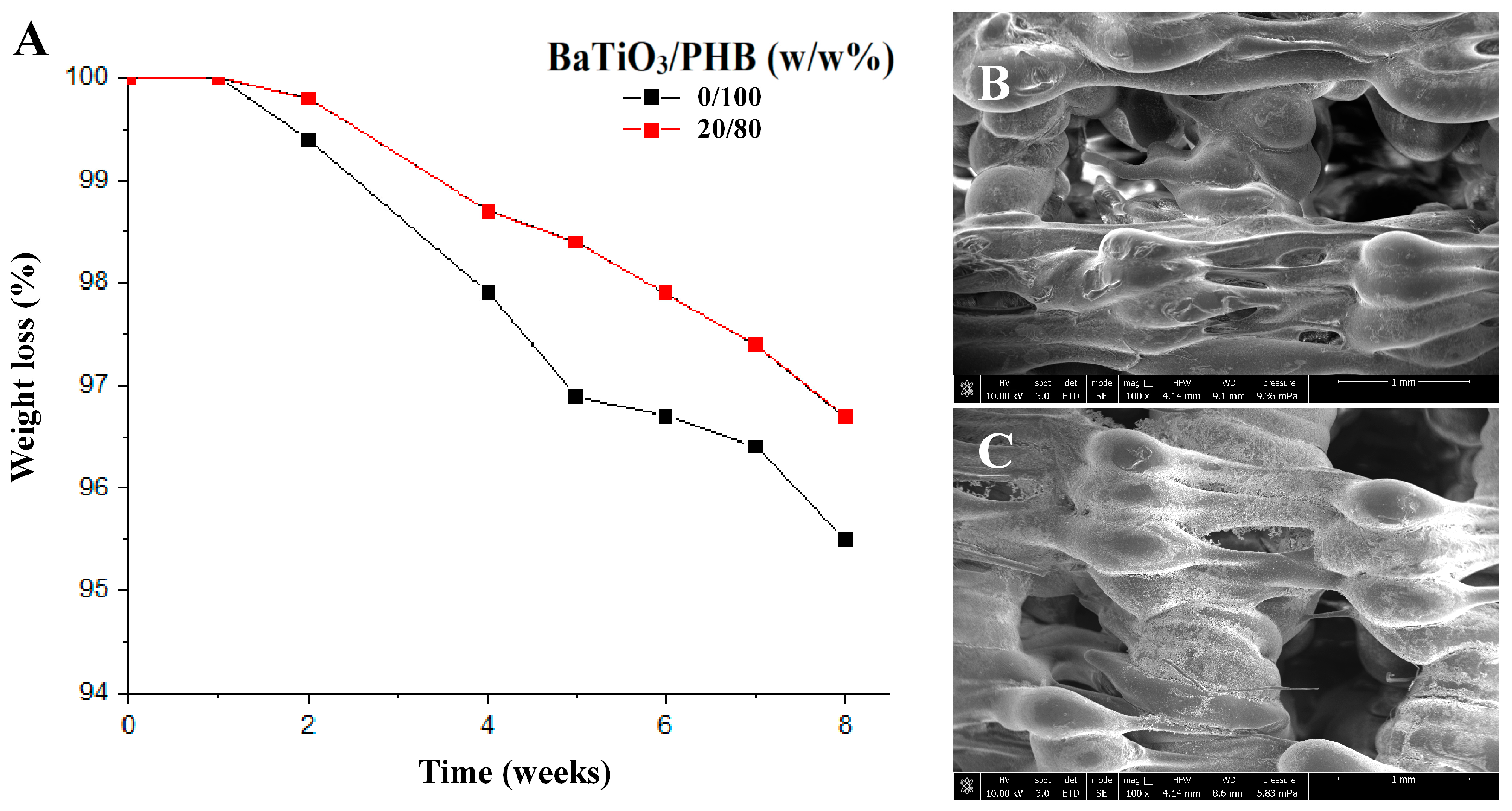
3. Results
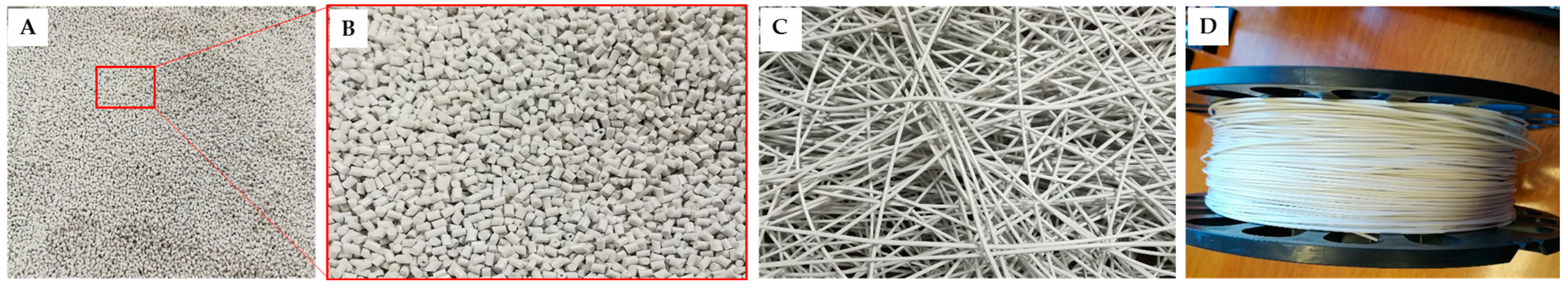
3.1. Production of the Nanocomposites
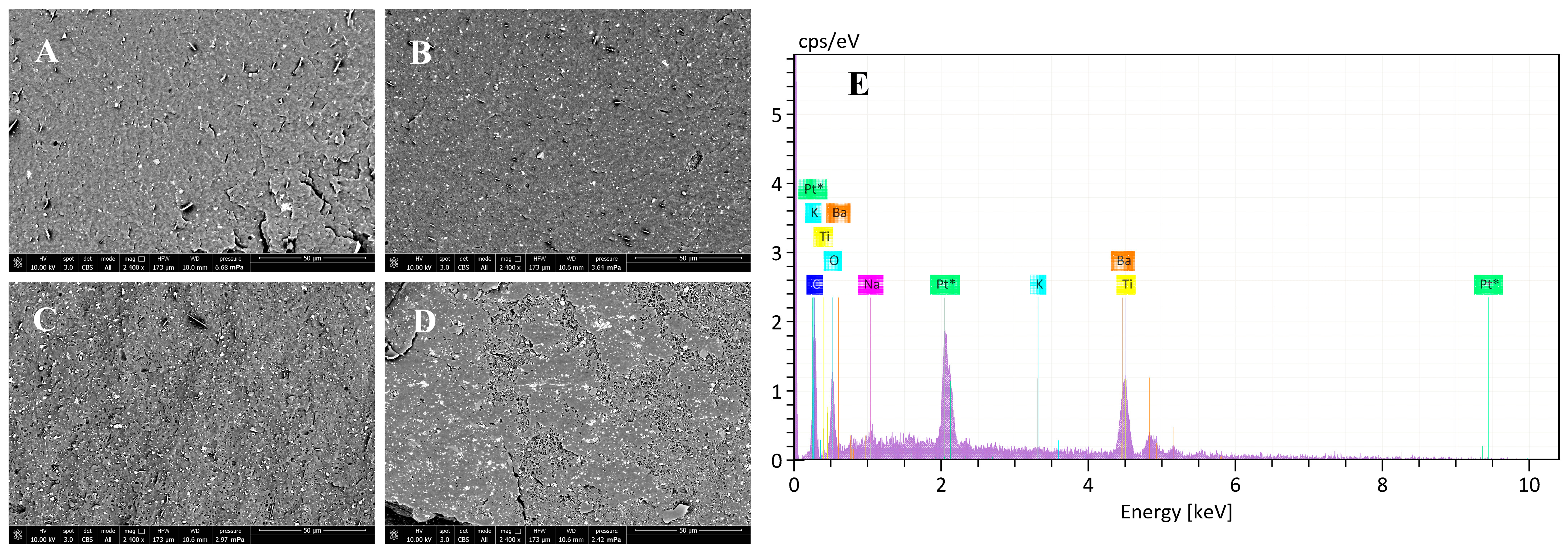
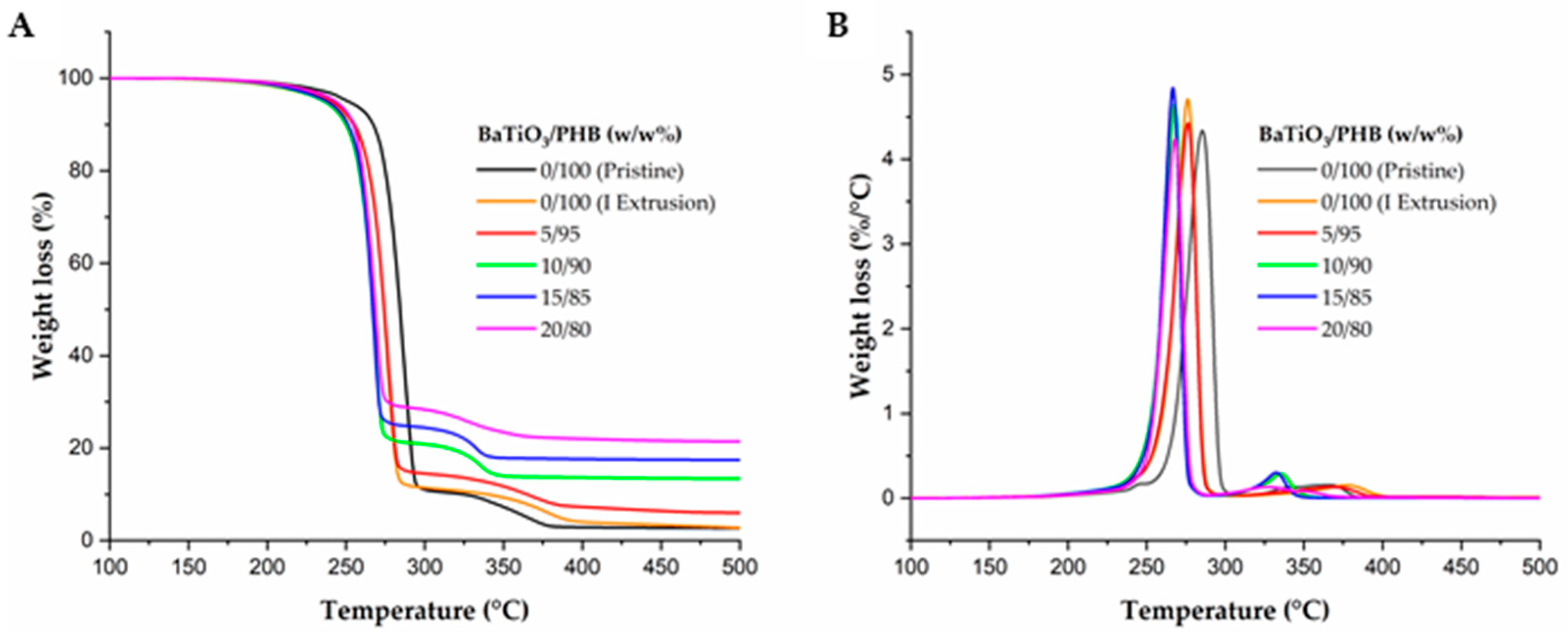
3.2. Characterization of the Nanocomposites
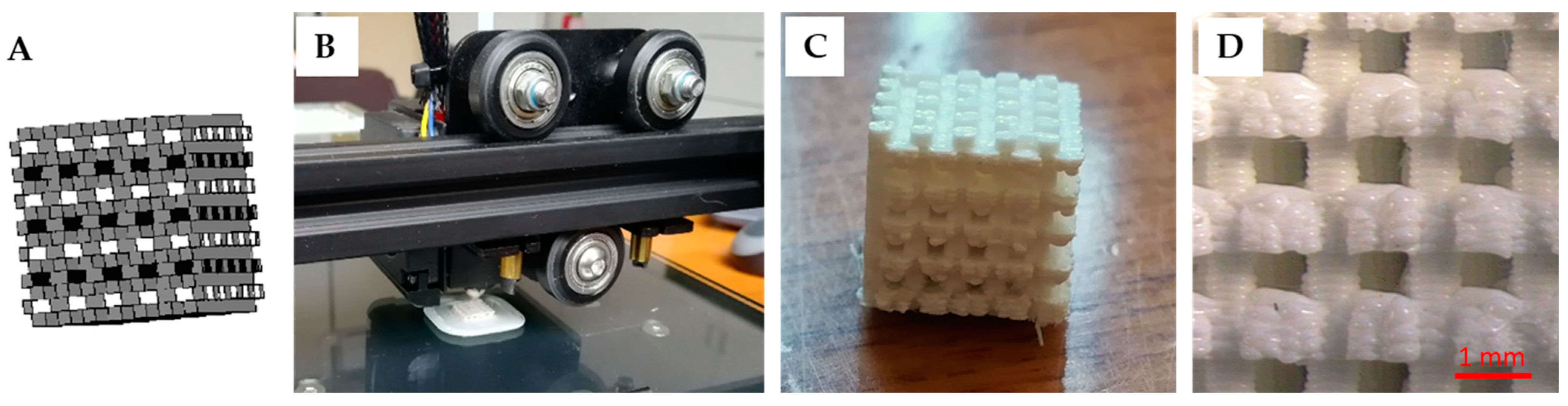
3.3. Production of the Nanocomposite Scaffolds
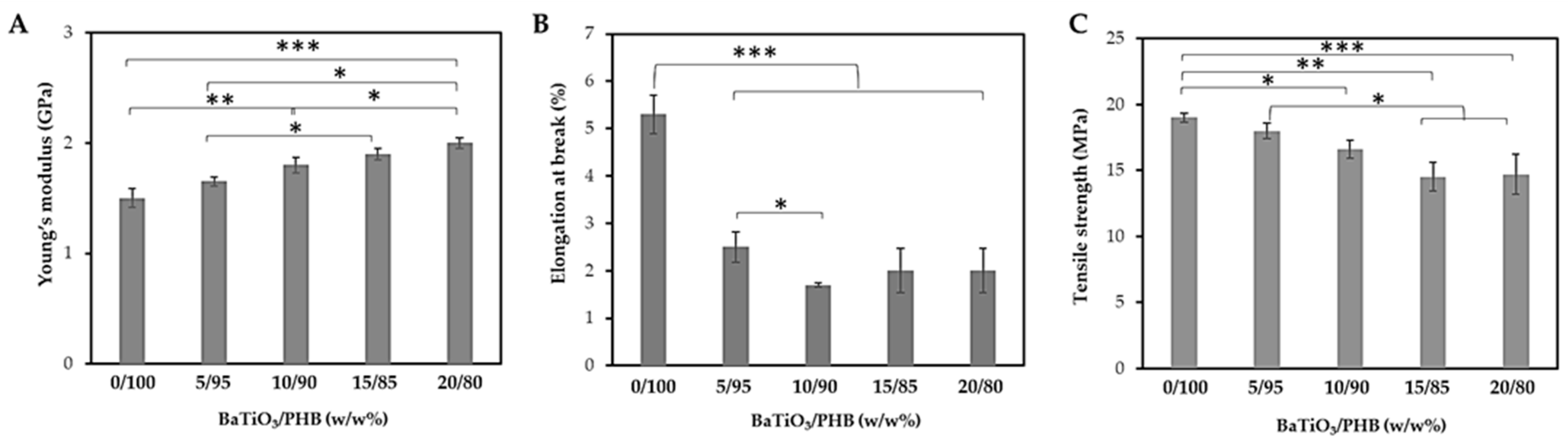
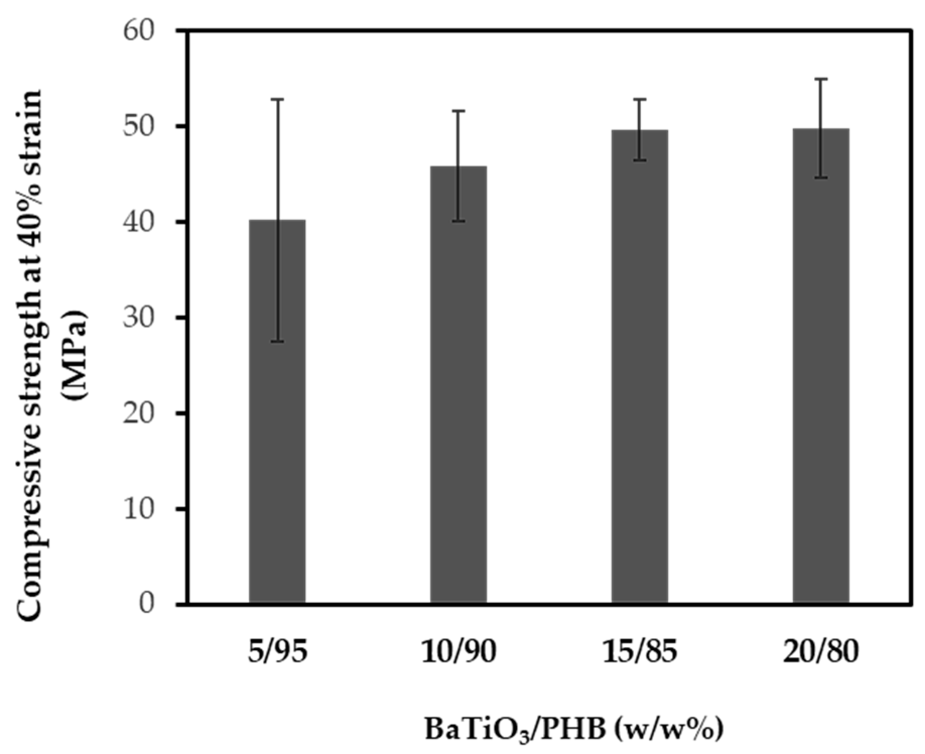
3.4. Characterization of the Nanocomposite Scaffolds
4. Discussion
5. Conclusions
Supplementary Materials
Author Contributions
Funding
Institutional Review Board Statement
Informed Consent Statement
Data Availability Statement
Acknowledgments
Conflicts of Interest
References
- Majidinia, M.; Sadeghpour, A.; Yousefi, B. The Roles of Signaling Pathways in Bone Repair and Regeneration. J. Cell. Physiol. 2018, 233, 2937–2948. [Google Scholar] [CrossRef] [PubMed]
- Poggetti, A.; Rosati, M.; Castellini, I.; Evangelisti, G.; Battistini, P.; Parchi, P.; Lisanti, M. Treatment of Scaphoid Waist Nonunion Using Olecranon Bone Graft and Stryker Asnis Micro Cannulated Screw: A Retrospective Study—80 Case Studies and 6 Years of Follow-Up. J. Wrist Surg. 2015, 4, 194–199. [Google Scholar] [PubMed]
- Bruschini, P.; Berrettini, S.; Segnini, G.; Sellari Franceschini, S.; Bocci, S.; Piragine, F.; Gersdorff, M. Omotrapianti Ossei Liofilizzati Nella Chirurgia Ricostruttiva Dell’orecchio Medio. Acta Otorhinolaryngol. Ital. 1991, 11, 159–165. [Google Scholar] [PubMed]
- D’Alessandro, D.; Perale, G.; Milazzo, M.; Moscato, S.; Stefanini, C.; Pertici, G.; Danti, S. Bovine Bone Matrix/Poly (l-Lactic-Co-ε-Caprolactone)/Gelatin Hybrid Scaffold (SmartBone®) for Maxillary Sinus Augmentation: A Histologic Study on Bone Regeneration. Int. J. Pharm. 2017, 523, 534–544. [Google Scholar] [CrossRef] [PubMed]
- Baldwin, P.; Li, D.J.; Auston, D.A.; Mir, H.S.; Yoon, R.S.; Koval, K.J. Autograft, Allograft, and Bone Graft Substitutes: Clinical Evidence and Indications for Use in the Setting of Orthopaedic Trauma Surgery. J. Orthop. Trauma 2019, 33, 203–213. [Google Scholar] [CrossRef]
- Giannoudis, P.V.; Dinopoulos, H.; Tsiridis, E. Bone Substitutes: An Update. Injury 2005, 36, S20–S27. [Google Scholar] [CrossRef]
- Wang, W.; Yeung, K.W.K. Bone Grafts and Biomaterials Substitutes for Bone Defect Repair: A Review. Bioact. Mater. 2017, 2, 224–247. [Google Scholar] [CrossRef]
- Costantino, P.D.; Hiltzik, D.; Govindaraj, S.; Moche, J. Bone Healing and Bone Substitutes. Facial Plast. Surg. 2002, 18, 13–26. [Google Scholar] [CrossRef] [PubMed]
- Haugen, H.J.; Lyngstadaas, S.P.; Rossi, F.; Perale, G. Bone Grafts: Which Is the Ideal Biomaterial? J. Clin. Periodontol. 2019, 46, 92–102. [Google Scholar] [CrossRef] [PubMed]
- Wubneh, A.; Tsekoura, E.K.; Ayranci, C.; Uludağ, H. Current State of Fabrication Technologies and Materials for Bone Tissue Engineering. Acta Biomater. 2018, 80, 1–30. [Google Scholar] [CrossRef]
- Giannotti, S.; Trombi, L.; Bottai, V.; Ghilardi, M.; D’Alessandro, D.; Danti, S.; Dell’Osso, G.; Guido, G.; Petrini, M. Use of Autologous Human Mesenchymal Stromal Cell/Fibrin Clot Constructs in Upper Limb Non-Unions: Long-Term Assessment. PLoS ONE 2013, 8, e73893. [Google Scholar] [CrossRef]
- Danti, S.; Serino, L.P.; D’Alessandro, D.; Moscato, S.; Danti, S.; Trombi, L.; Dinucci, D.; Chiellini, F.; Pietrabissa, A.; Lisanti, M.; et al. Growing Bone Tissue-Engineered Niches with Graded Osteogenicity: An in Vitro Method for Biomimetic Construct Assembly. Tissue Eng. Part C Methods 2013, 19, 911–924. [Google Scholar] [CrossRef]
- Bharadwaz, A.; Jayasuriya, A.C. Recent Trends in the Application of Widely Used Natural and Synthetic Polymer Nanocomposites in Bone Tissue Regeneration. Mater. Sci. Eng. C 2020, 110, 110698. [Google Scholar] [CrossRef] [PubMed]
- Bahraminasab, M.; Janmohammadi, M.; Arab, S.; Talebi, A.; Nooshabadi, V.T.; Koohsarian, P.; Nourbakhsh, M.S. Bone Scaffolds: An Incorporation of Biomaterials, Cells, and Biofactors. ACS Biomater. Sci. Eng. 2021, 7, 5397–5431. [Google Scholar] [CrossRef]
- Santos, M.I.; Reis, R.L. Vascularization in Bone Tissue Engineering: Physiology, Current Strategies, Major Hurdles and Future Challenges. Macromol. Biosci. 2010, 10, 12–27. [Google Scholar] [CrossRef] [PubMed]
- D’Alessandro, D.; Ricci, C.; Milazzo, M.; Strangis, G.; Forli, F.; Buda, G.; Petrini, M.; Berrettini, S.; Uddin, M.J.; Danti, S.; et al. Piezoelectric Signals in Vascularized Bone Regeneration. Biomolecules 2021, 11, 1731. [Google Scholar] [CrossRef]
- Arnau, A.; Soares, D. Fundamentals of Piezoelectricity. In Piezoelectric Transducers and Applications; Springer: Berlin/Heidelberg, Germany, 2009; pp. 1–38. [Google Scholar]
- Khare, D.; Basu, B.; Dubey, A.K. Electrical Stimulation and Piezoelectric Biomaterials for Bone Tissue Engineering Applications. Biomaterials 2020, 258, 120280. [Google Scholar]
- Cafarelli, A.; Losi, P.; Salgarella, A.R.; Barsotti, M.C.; Di Cioccio, I.B.; Foffa, I.; Vannozzi, L.; Pingue, P.; Soldani, G.; Ricotti, L. Small-Caliber Vascular Grafts Based on a Piezoelectric Nanocomposite Elastomer: Mechanical Properties and Biocompatibility. J. Mech. Behav. Biomed. Mater. 2019, 97, 138–148. [Google Scholar] [CrossRef] [PubMed]
- Minary-Jolandan, M.; Yu, M.-F. Nanoscale Characterization of Isolated Individual Type I Collagen Fibrils: Polarization and Piezoelectricity. Nanotechnology 2009, 20, 85706. [Google Scholar] [CrossRef]
- Nix, E.L.; Ward, I.M. The Measurement of the Shear Piezoelectric Coefficients of Polyvinylidene Fluoride. Ferroelectrics 1986, 67, 137–141. [Google Scholar] [CrossRef]
- Das, K.K.; Basu, B.; Maiti, P.; Dubey, A.K. Piezoelectric Nanogenerators for Self-Powered Wearable and Implantable Bioelectronic Devices. Acta Biomater. 2023, 171, 85–113. [Google Scholar] [CrossRef]
- Azimi, B.; Sorayani Bafqi, M.S.; Fusco, A.; Ricci, C.; Gallone, G.; Bagherzadeh, R.; Donnarumma, G.; Uddin, M.J.; Latifi, M.; Lazzeri, A.; et al. Electrospun ZnO/Poly (Vinylidene Fluoride-Trifluoroethylene) Scaffolds for Lung Tissue Engineering. Tissue Eng. Part A 2020, 26, 1312–1331. [Google Scholar] [CrossRef]
- Fukada, E.; Ando, Y. Piezoelectric Properties of Poly-β-Hydroxybutyrate and Copolymers of β-Hydroxybutyrate and β-Hydroxyvalerate. Int. J. Biol. Macromol. 1986, 8, 361–366. [Google Scholar] [CrossRef]
- Ke, S.; Huang, H.; Ren, L.; Wang, Y. Nearly Constant Dielectric Loss Behavior in Poly (3-Hydroxybutyrate-Co-3-Hydroxyvalerate) Biodegradable Polyester. J. Appl. Phys. 2009, 105, 096103. [Google Scholar] [CrossRef]
- Chernozem, R.V.; Surmeneva, M.A.; Shkarina, S.N.; Loza, K.; Epple, M.; Ulbricht, M.; Cecilia, A.; Krause, B.; Baumbach, T.; Abalymov, A.A.; et al. Piezoelectric 3-D Fibrous Poly (3-Hydroxybutyrate)-Based Scaffolds Ultrasound-Mineralized with Calcium Carbonate for Bone Tissue Engineering: Inorganic Phase Formation, Osteoblast Cell Adhesion, and Proliferation. ACS Appl. Mater. Interfaces 2019, 11, 19522–19533. [Google Scholar] [CrossRef]
- Zhang, Y.-Q.; Geng, Q.; Li, C.; Wang, H.-C.; Ren, C.; Zhang, Y.-F.; Bai, J.-S.; Pan, H.-B.; Cui, X.; Yao, M.-X.; et al. Application of Piezoelectric Materials in the Field of Bone: A Bibliometric Analysis. Front. Bioeng. Biotechnol. 2023, 11, 1210637. [Google Scholar] [CrossRef]
- Hao, J.; Li, W.; Zhai, J.; Chen, H. Progress in High-Strain Perovskite Piezoelectric Ceramics. Mater. Sci. Eng. R Rep. 2019, 135, 1–57. [Google Scholar] [CrossRef]
- Rödel, J.; Jo, W.; Seifert, K.T.P.; Anton, E.; Granzow, T.; Damjanovic, D. Perspective on the Development of Lead-free Piezoceramics. J. Am. Ceram. Soc. 2009, 92, 1153–1177. [Google Scholar] [CrossRef]
- Mindlin, R.D. Elasticity, Piezoelectricity and Crystal Lattice Dynamics. J. Elast. 1972, 2, 217–282. [Google Scholar] [CrossRef]
- Berlincourt, D.; Jaffe, H. Elastic and Piezoelectric Coefficients of Single-Crystal Barium Titanate. Phys. Rev. 1958, 111, 143. [Google Scholar] [CrossRef]
- Ehterami, A.; Kazemi, M.; Nazari, B.; Saraeian, P.; Azami, M. Fabrication and Characterization of Highly Porous Barium Titanate Based Scaffold Coated by Gel/HA Nanocomposite with High Piezoelectric Coefficient for Bone Tissue Engineering Applications. J. Mech. Behav. Biomed. Mater. 2018, 79, 195–202. [Google Scholar] [CrossRef]
- Haeldermans, T.; Samyn, P.; Cardinaels, R.; Vandamme, D.; Vanreppelen, K.; Cuypers, A.; Schreurs, S. Bio-Based Poly (3-Hydroxybutyrate)/Thermoplastic Starch Composites as a Host Matrix for Biochar Fillers. J. Polym. Environ. 2021, 29, 2478–2491. [Google Scholar] [CrossRef]
- Righetti, M.C.; Tombari, E.; di Lorenzo, M.L. The Role of the Crystallization Temperature on the Nanophase Structure Evolution of Poly [(R)-3-Hydroxybutyrate]. J. Phys. Chem. B 2013, 117, 12303–12311. [Google Scholar] [CrossRef]
- Di Lorenzo, M.L.; Gazzano, M.; Righetti, M.C. The Role of the Rigid Amorphous Fraction on Cold Crystallization of Poly (3-Hydroxybutyrate). Macromolecules 2012, 45, 5684–5691. [Google Scholar] [CrossRef]
- Mota, C.; Labardi, M.; Trombi, L.; Astolfi, L.; D’Acunto, M.; Puppi, D.; Gallone, G.; Chiellini, F.; Berrettini, S.; Bruschini, L.; et al. Design, Fabrication and Characterization of Composite Piezoelectric Ultrafine Fibers for Cochlear Stimulation. Mater. Des. 2017, 122, 206–219. [Google Scholar] [CrossRef]
- Lee, K.-W.; Wang, S.; Lu, L.; Jabbari, E.; Currier, B.L.; Yaszemski, M.J. Fabrication and Characterization of Poly (Propylene Fumarate) Scaffolds with Controlled Pore Structures Using 3-Dimensional Printing and Injection Molding. Tissue Eng. 2006, 12, 2801–2811. [Google Scholar] [CrossRef]
- Hu, Y.; Grainger, D.W.; Winn, S.R.; Hollinger, J.O. Fabrication of Poly (A-hydroxy Acid) Foam Scaffolds Using Multiple Solvent Systems. J. Biomed. Mater. Res. Off. J. Soc. Biomater. Jpn. Soc. Biomater. Aust. Soc. Biomater. Korean Soc. Biomater. 2002, 59, 563–572. [Google Scholar] [CrossRef]
- Ingber, D.E.; Mow, V.C.; Butler, D.; Niklason, L.; Huard, J.; Mao, J.; Yannas, I.; Kaplan, D.; Vunjak-Novakovic, G. Tissue Engineering and Developmental Biology: Going Biomimetic. Tissue Eng. 2006, 12, 3265–3283. [Google Scholar] [CrossRef]
- Guilak, F.; Butler, D.L.; Goldstein, S.A.; Baaijens, F.P.T. Biomechanics and Mechanobiology in Functional Tissue Engineering. J. Biomech. 2014, 47, 1933–1940. [Google Scholar] [CrossRef]
- Lopes, D.; Martins-Cruz, C.; Oliveira, M.B.; Mano, J.F. Bone Physiology as Inspiration for Tissue Regenerative Therapies. Biomaterials 2018, 185, 240–275. [Google Scholar] [CrossRef]
- da Silva, L.P.; Kundu, S.C.; Reis, R.L.; Correlo, V.M. Electric Phenomenon: A Disregarded Tool in Tissue Engineering and Regenerative Medicine. Trends Biotechnol. 2020, 38, 24–49. [Google Scholar] [CrossRef]
- Balint, R.; Cassidy, N.J.; Cartmell, S.H. Electrical Stimulation: A Novel Tool for Tissue Engineering. Tissue Eng. Part B Rev. 2013, 19, 48–57. [Google Scholar] [CrossRef]
- Fukada, E.; Yasuda, I. Piezoelectric Effects in Collagen. Jpn. J. Appl. Phys. 1964, 3, 117. [Google Scholar] [CrossRef]
- Lang, S.B.; Tofail, S.A.M.; Kholkin, A.L.; Wojtaś, M.; Gregor, M.; Gandhi, A.A.; Wang, Y.; Bauer, S.; Krause, M.; Plecenik, A. Ferroelectric Polarization in Nanocrystalline Hydroxyapatite Thin Films on Silicon. Sci. Rep. 2013, 3, 2215. [Google Scholar] [CrossRef]
- Fukada, E.; Hara, K. Piezoelectric Effect in Blood Vessel Walls. J. Phys. Soc. Jpn. 1969, 26, 777–780. [Google Scholar] [CrossRef]
- Robert, L.; Jacob, M.P.; Fulop, T. Elastin in Blood Vessels. Mol. Biol. Pathol. Elastic Tissues 1995, 192, 286–303. [Google Scholar]
- Schott, N.G.; Friend, N.E.; Stegemann, J.P. Coupling Osteogenesis and Vasculogenesis in Engineered Orthopedic Tissues. Tissue Eng. Part B Rev. 2021, 27, 199–214. [Google Scholar] [CrossRef]
- Bahraminasab, M. Challenges on Optimization of 3D-Printed Bone Scaffolds. Biomed. Eng. Online 2020, 19, 69. [Google Scholar] [CrossRef]
- Guo, W.; Yang, K.; Qin, X.; Luo, R.; Wang, H.; Huang, R. Polyhydroxyalkanoates in Tissue Repair and Regeneration. Eng. Regen. 2022, 3, 24–40. [Google Scholar] [CrossRef]
- Barbosa, F.; Garrudo, F.F.F.; Alberte, P.S.; Resina, L.; Carvalho, M.S.; Jain, A.; Marques, A.C.; Estrany, F.; Rawson, F.J.; Aléman, C.; et al. Hydroxyapatite-Filled Osteoinductive and Piezoelectric Nanofibers for Bone Tissue Engineering. Sci. Technol. Adv. Mater. 2023, 24, 2242242. [Google Scholar] [CrossRef]
- Goonoo, N.; Bhaw-Luximon, A.; Passanha, P.; Esteves, S.R.; Jhurry, D. Third Generation Poly (Hydroxyacid) Composite Scaffolds for Tissue Engineering. J. Biomed. Mater. Res. Part B Appl. Biomater. 2017, 105, 1667–1684. [Google Scholar] [CrossRef]
- Koosha, F.; Muller, R.H.; Davis, S.S. Polyhydroxybutyrate as a Drug Carrier. Crit. Rev. Ther. Drug Carrier Syst. 1989, 6, 117–130. [Google Scholar]
- Lee, J.; Park, H.J.; Moon, M.; Lee, J.-S.; Min, K. Recent Progress and Challenges in Microbial Polyhydroxybutyrate (PHB) Production from CO2 as a Sustainable Feedstock: A State-of-the-Art Review. Bioresour. Technol. 2021, 339, 125616. [Google Scholar] [CrossRef]
- Mohan, A.; Girdhar, M.; Kumar, R.; Chaturvedi, H.S.; Vadhel, A.; Solanki, P.R.; Kumar, A.; Kumar, D.; Mamidi, N. Polyhydroxybutyrate-Based Nanocomposites for Bone Tissue Engineering. Pharmaceuticals 2021, 14, 1163. [Google Scholar] [CrossRef]
- Sood, A.; Desseigne, M.; Dev, A.; Maurizi, L.; Kumar, A.; Millot, N.; Han, S.S. A Comprehensive Review on Barium Titanate Nanoparticles as a Persuasive Piezoelectric Material for Biomedical Applications: Prospects and Challenges. Small 2023, 19, 2206401. [Google Scholar] [CrossRef]
- Lemes, A.P.; Soto-Oviedo, M.A.; Innocentini Mei, L.H.; Durán, N. Processing, Chemical Structure and Morphology of Poly (Hydroxybutyrate-Co-Valerate)/Lignosulfonate Composites. In 4th Mercosur Congress on Process Systems Engineering, 2nd Mercosur Congress on Chemical Engineering: Proceedings of ENPROMER 2005; E-Papers Serviços Editoriais: Rio de Janeiro, Brazil, 2005; pp. 1–6. [Google Scholar]
- Lohse, D.J.; Milner, S.T.; Fetters, L.J.; Xenidou, M.; Hadjichristidis, N.; Mendelson, R.A.; Garcia-Franco, C.A.; Lyon, M.K. Well-Defined, Model Long Chain Branched Polyethylene. 2. Melt Rheological Behavior. Macromolecules 2002, 35, 3066–3075. [Google Scholar] [CrossRef]
- Pradhan, S.; Dikshit, P.K.; Moholkar, V.S. Production, Ultrasonic Extraction, and Characterization of Poly (3-Hydroxybutyrate)(PHB) Using Bacillus Megaterium and Cupriavidus Necator. Polym. Adv. Technol. 2018, 29, 2392–2400. [Google Scholar] [CrossRef]
- Deshmukh, G.S.; Peshwe, D.R.; Pathak, S.U.; Ekhe, J.D. Nonisothermal Crystallization Kinetics and Melting Behavior of Poly (Butylene Terephthalate)(PBT) Composites Based on Different Types of Functional Fillers. Thermochim. Acta 2014, 581, 41–53. [Google Scholar] [CrossRef]
- Lugoloobi, I.; Li, X.; Zhang, Y.; Mao, Z.; Wang, B.; Sui, X.; Feng, X. Fabrication of Lignin/Poly (3-Hydroxybutyrate) Nanocomposites with Enhanced Properties via a Pickering Emulsion Approach. Int. J. Biol. Macromol. 2020, 165, 3078–3087. [Google Scholar] [CrossRef]
- Srubar, W.V., III; Pilla, S.; Wright, Z.C.; Ryan, C.A.; Greene, J.P.; Frank, C.W.; Billington, S.L. Mechanisms and Impact of Fiber--Matrix Compatibilization Techniques on the Material Characterization of PHBV/Oak Wood Flour Engineered Biobased Composites. Compos. Sci. Technol. 2012, 72, 708–715. [Google Scholar] [CrossRef]
- Gunaratne, L.; Shanks, R.A. Melting and Thermal History of Poly (Hydroxybutyrate-Co-Hydroxyvalerate) Using Step-Scan DSC. Thermochim. Acta 2005, 430, 183–190. [Google Scholar] [CrossRef]
- Stern, N.; Hu, X.; Marom, G. The Effects of Geometry and Chemical Composition of Nanoparticles on the Fracture Toughness of IPP Nanocomposites. J. Compos. Sci. 2020, 4, 24. [Google Scholar] [CrossRef]
- Wu, D.; Isaksson, P.; Ferguson, S.J.; Persson, C. Young’s Modulus of Trabecular Bone at the Tissue Level: A Review. Acta Biomater. 2018, 78, 1–12. [Google Scholar] [CrossRef]
- de O. Patrício, P.S.; Pereira, F.V.; dos Santos, M.C.; de Souza, P.P.; Roa, J.P.B.; Orefice, R.L. Increasing the Elongation at Break of Polyhydroxybutyrate Biopolymer: Effect of Cellulose Nanowhiskers on Mechanical and Thermal Properties. J. Appl. Polym. Sci. 2013, 127, 3613–3621. [Google Scholar] [CrossRef]
- Danti, S.; Azimi, B.; Candito, M.; Fusco, A.; Sorayani Bafqi, M.S.; Ricci, C.; Milazzo, M.; Cristallini, C.; Latifi, M.; Donnarumma, G.; et al. Lithium Niobate Nanoparticles as Biofunctional Interface Material for Inner Ear Devices. Biointerphases 2020, 15, 31004. [Google Scholar] [CrossRef]
- Milazzo, M.; Contessi Negrini, N.; Scialla, S.; Marelli, B.; Farè, S.; Danti, S.; Buehler, M.J. Additive Manufacturing Approaches for Hydroxyapatite-Reinforced Composites. Adv. Funct. Mater. 2019, 29, 1903055. [Google Scholar] [CrossRef]
- Akaraonye, E.; Keshavarz, T.; Roy, I. Production of Polyhydroxyalkanoates: The Future Green Materials of Choice. J. Chem. Technol. Biotechnol. 2010, 85, 732–743. [Google Scholar] [CrossRef]
- Han, J.; Wu, L.-P.; Liu, X.-B.; Hou, J.; Zhao, L.-L.; Chen, J.-Y.; Zhao, D.-H.; Xiang, H. Biodegradation and Biocompatibility of Haloarchaea-Produced Poly (3-Hydroxybutyrate-Co-3-Hydroxyvalerate) Copolymers. Biomaterials 2017, 139, 172–186. [Google Scholar] [CrossRef]
- Aspenberg, P. Accelerating Fracture Repair in Humans: A Reading of Old Experiments and Recent Clinical Trials. Bonekey Rep. 2013, 2, 244. [Google Scholar] [CrossRef]
- Coltelli, M.-B.; Aliotta, L.; Vannozzi, A.; Morganti, P.; Panariello, L.; Danti, S.; Neri, S.; Fernandez-Avila, C.; Fusco, A.; Donnarumma, G.; et al. Properties and Skin Compatibility of Films Based on Poly(Lactic Acid) (PLA) Bionanocomposites Incorporating Chitin Nanofibrils (CN). J. Funct. Biomater. 2020, 11, 21. [Google Scholar] [CrossRef]


| BaTiO3 Weight Fraction | BaTiO3/PHB (w/w%) |
|---|---|
| 0 (plain PHB) | 0/100 |
| 0.05 | 5/95 |
| 0.10 | 10/90 |
| 0.15 | 15/85 |
| 0.20 | 20/80 |
| BaTiO3/PHB (w/w%) | Tm (°C) | Tg (°C) | Xc-heat (%) | Tc (°C) | Xc-cool (%) |
|---|---|---|---|---|---|
| 0/100 | 172 | 12 | 60 | 113 | 60 |
| 5/95 | 172 | 9 | 50 | 111 | 53 |
| 10/90 | 172 | 6 | 51 | 111 | 50 |
| 15/85 | 173 | 6 | 51 | 112 | 51 |
| 20/80 | 173 | 5 | 48 | 111 | 52 |
| Extrusion Cycle | Compressive Strength (MPa) |
|---|---|
| 0 | 45.9 ± 5.0 |
| I | 38.8 ± 6.0 |
| IV | 36.0 ± 2.0 |
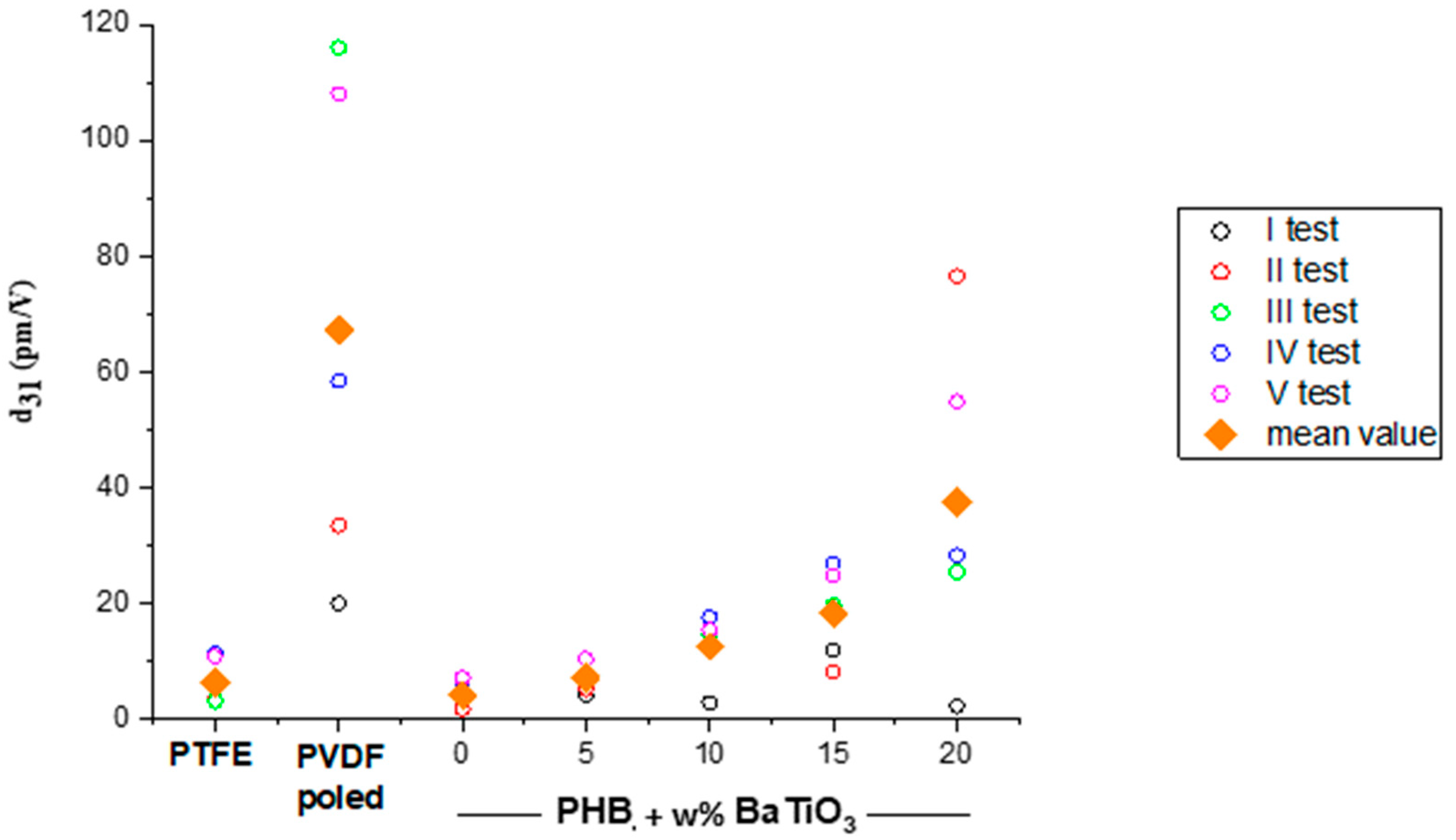
| BaTiO3/PHB (w/w%) | εd | d31 (pm/V) | g31 (Vm/N) |
|---|---|---|---|
| 0/100 | 4.15 | 4.15 | 0.113 |
| 5/95 | 4.81 | 7.03 | 0.165 |
| 10/90 | 5.00 | 12.56 | 0.284 |
| 15/85 | 5.78 | 18.30 | 0.358 |
| 20/80 | 6.29 | 37.46 | 0.673 |
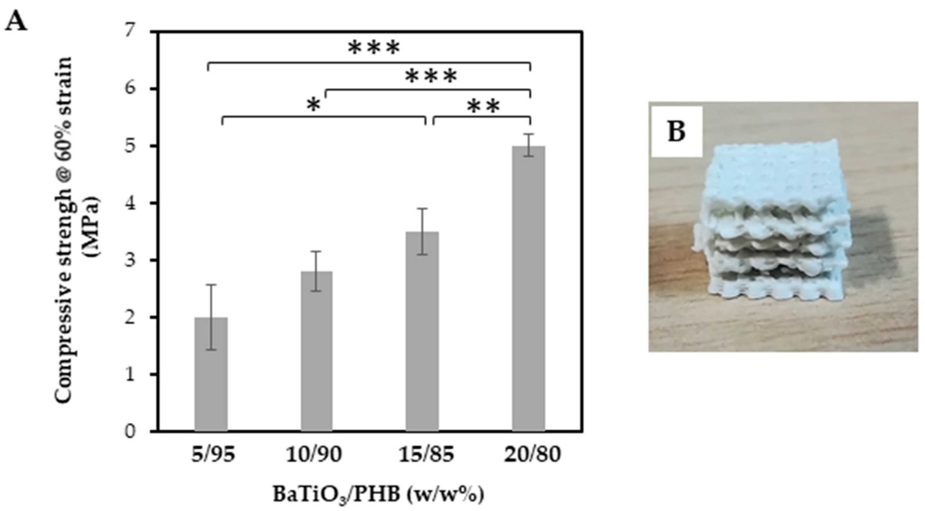
| BaTiO3/PHB (w/w%) | Pore Size (mm) | Porosity (%) | ||
|---|---|---|---|---|
| Designed | Experimental | Designed | Experimental | |
| 0/100 | 1.00 | 0.77 | 70 | 62 |
| 5/95 | 1.00 | 0.60 | 70 | 54 |
| 20/80 | 1.00 | 0.66 | 70 | 58 |
Disclaimer/Publisher’s Note: The statements, opinions and data contained in all publications are solely those of the individual author(s) and contributor(s) and not of MDPI and/or the editor(s). MDPI and/or the editor(s) disclaim responsibility for any injury to people or property resulting from any ideas, methods, instructions or products referred to in the content. |
© 2024 by the authors. Licensee MDPI, Basel, Switzerland. This article is an open access article distributed under the terms and conditions of the Creative Commons Attribution (CC BY) license (https://creativecommons.org/licenses/by/4.0/).
Share and Cite
Strangis, G.; Labardi, M.; Gallone, G.; Milazzo, M.; Capaccioli, S.; Forli, F.; Cinelli, P.; Berrettini, S.; Seggiani, M.; Danti, S.; et al. 3D Printed Piezoelectric BaTiO3/Polyhydroxybutyrate Nanocomposite Scaffolds for Bone Tissue Engineering. Bioengineering 2024, 11, 193. https://doi.org/10.3390/bioengineering11020193
Strangis G, Labardi M, Gallone G, Milazzo M, Capaccioli S, Forli F, Cinelli P, Berrettini S, Seggiani M, Danti S, et al. 3D Printed Piezoelectric BaTiO3/Polyhydroxybutyrate Nanocomposite Scaffolds for Bone Tissue Engineering. Bioengineering. 2024; 11(2):193. https://doi.org/10.3390/bioengineering11020193
Chicago/Turabian StyleStrangis, Giovanna, Massimiliano Labardi, Giuseppe Gallone, Mario Milazzo, Simone Capaccioli, Francesca Forli, Patrizia Cinelli, Stefano Berrettini, Maurizia Seggiani, Serena Danti, and et al. 2024. "3D Printed Piezoelectric BaTiO3/Polyhydroxybutyrate Nanocomposite Scaffolds for Bone Tissue Engineering" Bioengineering 11, no. 2: 193. https://doi.org/10.3390/bioengineering11020193
APA StyleStrangis, G., Labardi, M., Gallone, G., Milazzo, M., Capaccioli, S., Forli, F., Cinelli, P., Berrettini, S., Seggiani, M., Danti, S., & Parchi, P. (2024). 3D Printed Piezoelectric BaTiO3/Polyhydroxybutyrate Nanocomposite Scaffolds for Bone Tissue Engineering. Bioengineering, 11(2), 193. https://doi.org/10.3390/bioengineering11020193