Article

Simulating Flash Floods Using Geostationary Satellite-Based Rainfall Estimation Coupled with a Land Surface Model

by
Dwi Prabowo Yuga Suseno
1,* and
Tomohito J. Yamada
2,*
1
Directorate Protected Forest Management Unit, Ministry of Environment and Forestry Republic of Indonesia, Gedung Manggala Wanabhakti Blok I Lantai 12, Jl. Gatot Subroto, Senayan, Jakarta 10270, Indonesia
2
Faculty of Engineering, Hokkaido University, N13 W8, Kita-ku, Sapporo, Hokkaido 060-0808, Japan
*
Authors to whom correspondence should be addressed.
Hydrology 2020, 7(1), 9; https://doi.org/10.3390/hydrology7010009
Submission received: 26 September 2019 / Revised: 17 December 2019 / Accepted: 22 January 2020 / Published: 25 January 2020

Abstract

:
Clarifying hydrologic behavior, especially behavior related to extreme events such as flash floods, is vital for flood mitigation and management. However, discharge and rainfall measurement data are scarce, which is a major obstacle to flood mitigation. This study: (i) simulated flash floods on a regional scale using three types of rainfall forcing implemented in a land surface model; and (ii) evaluated and compared simulated flash floods with the observed discharge. The three types of rainfall forcing were those observed by the Automated Meteorological Data Acquisition System (AMeDAS) (Simulation I), the observed rainfall from the Ministry of Land, Infrastructure and Transportation (MLIT) (Simulation II), and the estimated rainfall from the Multi-purpose Transport Satellite (MTSAT), which was downscaled by AMeDAS rainfall (Simulation III). MLIT rainfall observations have a denser station network over the Ishikari River basin (spacing of approximately 10 km) compared with AMeDAS (spacing of approximately 20 km), so they are expected to capture the rainfall spatial distribution more accurately. A land surface model, the Minimal Advance Treatments of Surface Interaction and Runoff (MATSIRO), was implemented for the flash flood simulation. The river flow simulations were run over the Ishikari river basin at a 1-km grid resolution and a 1-h temporal resolution during August 2010. The statistical performance of the river flow simulations during a flash flood event on 23 and 24 August 2010 demonstrated that Simulation I was reasonable compared with Simulation III. The findings also suggest that the advantages of the MTSAT-based estimated rainfall (i.e., good spatial distribution) can be coupled with the benefit of direct AMeDAS observations (i.e., representation of the true rainfall).

1. Introduction

Clarifying the hydrological behavior of a catchment area, especially behavior related to extreme events such as flash floods, is vital for flood mitigation and management. Some studies have focused on flash flood mitigation, including risk estimation [1], early detection [2], and severity [3,4]. The magnitude of peak discharge and time to peak discharge during flash flood events are important parameters that should be assessed to help mitigate their disastrous effect. This information is usually derived by analyzing discharge measurements. However, problems arise when the catchment is ungauged because the gauges are damaged by hazards. Rainfall-runoff models are used to simulate discharge as an alternative way to obtain hydrologic data.
Rainfall observation network data are commonly employed as input data in rainfall-runoff models. However, these data tend to be sparse and unevenly distributed in space. Other challenges to developing high-density and well-configured rain gauge networks include limited funds, site accessibility, and network purposes [5]. Radar can be used to obtain the spatial distribution of rainfall, but this method is considered to be too expensive; high mountainous ranges can also block radar signals. Geostationary satellite-based rainfall estimation is an alternative way to provide continuous rainfall information, particularly for ungauged catchments [6,7]. Geostationary satellite images blended with microwave satellite rainfall measurements are preferable to the sole use of microwave satellite-based rainfall measurements, because geostationary satellites provide the advantage of capturing global coverage with a continuous acquisition time, which is very useful for monitoring purposes. Geostationary-based rainfall estimation can be coupled with a rainfall-runoff model to predict the flood discharge produced by a catchment [8]. In the past decade there have been some relatively improved methods published, as well as new geostationary satellite images available for satellite-based rainfall estimation such us GOES-R [9], Fengyun-4 [10], and the Communication, Oceanography and Meteorology Satellite (COMS) [11]. This indicates that the use of geostationary satellites for rainfall estimation purposes will increase in the future.
We conducted flash flood simulations based on a physical hydrological model called the Minimal Advance Treatments of Surface Interaction and Runoff (MATSIRO) [12]. MATSIRO uses physical processes to calculate the hydro-meteorological characteristics of a region, as expressed by energy balance and water balance models. It is a free and open source hydrological model in which is possible for the user to make some modifications. The coverage of those studies is a global scale mainly in 1° × 1° spatial resolution. Here, the river flow estimation module in MATSIRO was applied for flash flood simulation on a regional scale, with a grid size is refined of approximately 1 km × 1 km.
In this study, we had two objectives. The first was to simulate flash floods on a regional scale using three types of rainfall forcing, that is, observation by sparse stations, observation by dense stations and satellite rainfall estimation which is downscaled by rainfall from sparse observations. Considering that the density and the number of rainfall networks influence the accuracy significantly [13], our hypothesis is that denser rainfall networks will show the best performance. However, to arrange a dense and evenly distributed rainfall network could be costly and possibly not all of the area can be covered due to accessibility reasons. Here we combined the satellite rainfall estimation with the sparse rainfall data through a downscaling procedure. We expect that the downscaled rainfall estimation will have a comparable performance with a dense rainfall network, but operationally it will more cost effective than arranging a dense rainfall network. The second objective was to compare and evaluate the simulated river discharge with the observed discharge.

2. Materials and Methods

2.1. Brief Description of the MATSIRO

MATSIRO simulates the energy balance that is determined separately at the ground surface and canopy surface, and the energy and water exchange between the ground surface and the atmosphere [12]. To simulate the energy balance as well as the water exchange, MATSIRO uses two components: LNDFLX for determining the parameters and calculating the surface fluxes; and LNDSTP for treating the ground processes. The schematic diagram of MATSIRO is shown in Figure 1 and explained as following.
LNDFLX assesses external parameters that are prescribed as horizontal distributions (maps), such as land cover type (LC), soil type (SOIL), leaf area index (LAI), ground albedo (GALB), surface mean slope (SLOPE), and standard deviation of altitude in a grid cell (ELEVSTD). Input variables such as precipitation, wind velocity (U), atmospheric temperature (T), humidity (Q), pressure (P), and downward radiation (RD) variable are set. Next, the albedo, the aerodynamic resistance, the surface evaporation resistance and the stomatal resistance are evaluated based on the radiative transfer in the canopy, turbulent transfer, and photosynthesis. These input variables are used to diagnose the surface fluxes (the sensible and latent heat fluxes, the upward radiation, and the heat conduction into snow) and the surface energy balance (surface skin and canopy temperature).
LNDSTP calculates the canopy water budget, snow amount and runoff amount, and soil temperature and moisture are calculated based on precipitation (rainfall and snowfall) using the fluxes obtained by LNDFLX as the upper boundary condition. Here, the runoff is generated by considering four different mechanisms: (i) the ground water runoff (base runoff); (ii) the saturation excess runoff (Dunne mechanism); (iii) the infiltration excess runoff (Horton mechanism); and (iv) the overflow of the surface soil layer. This runoff is then routed through the river network using the Total Runoff Integration Pathways (TRIP) method [14]. By this process, a river flow accumulation is generated at every time-step, and the estimated river flow (discharge) can be observed at any position in the region, particularly in the outlet of the catchment.
The original and modified MATSIRO mainly used global data that is derived from global atmospheric data sets, such as the NCC (NCEP/NCAR Corrected by CRU) data forcing, the Global Soil Wetness Project (GSWP-2), the International Satellite Land Surface Climatology Project-Initiative II (ISLSCP-2), and the International Geosphere-Biosphere Programme, and vegetation properties [15]. For research at the regional scale, such as in this study, those data are considerably too coarse. Therefore, we focused on acquiring MATSIRO forcing data using remote sensing techniques which have relatively higher spatial resolution than the default data input usually used by MATSIRO. The use of remote sensing data is also intended to overcome the problems associated with the shortage of observed data.
Several types of remote sensing datasets were acquired for the MATSIRO forcing: the Moderate Resolution Imaging Spectroradiometer (MODIS); the Shuttle Radar Topographic Mission Digital Elevation Model (SRTM-DEM); the Cloud and Earth’s Radiant Energy System (CERES), and MTSAT images. Some primary and secondary data were also used, such as rainfall and meteorological observations, numerical weather prediction, and soil information.

2.2. Study Area

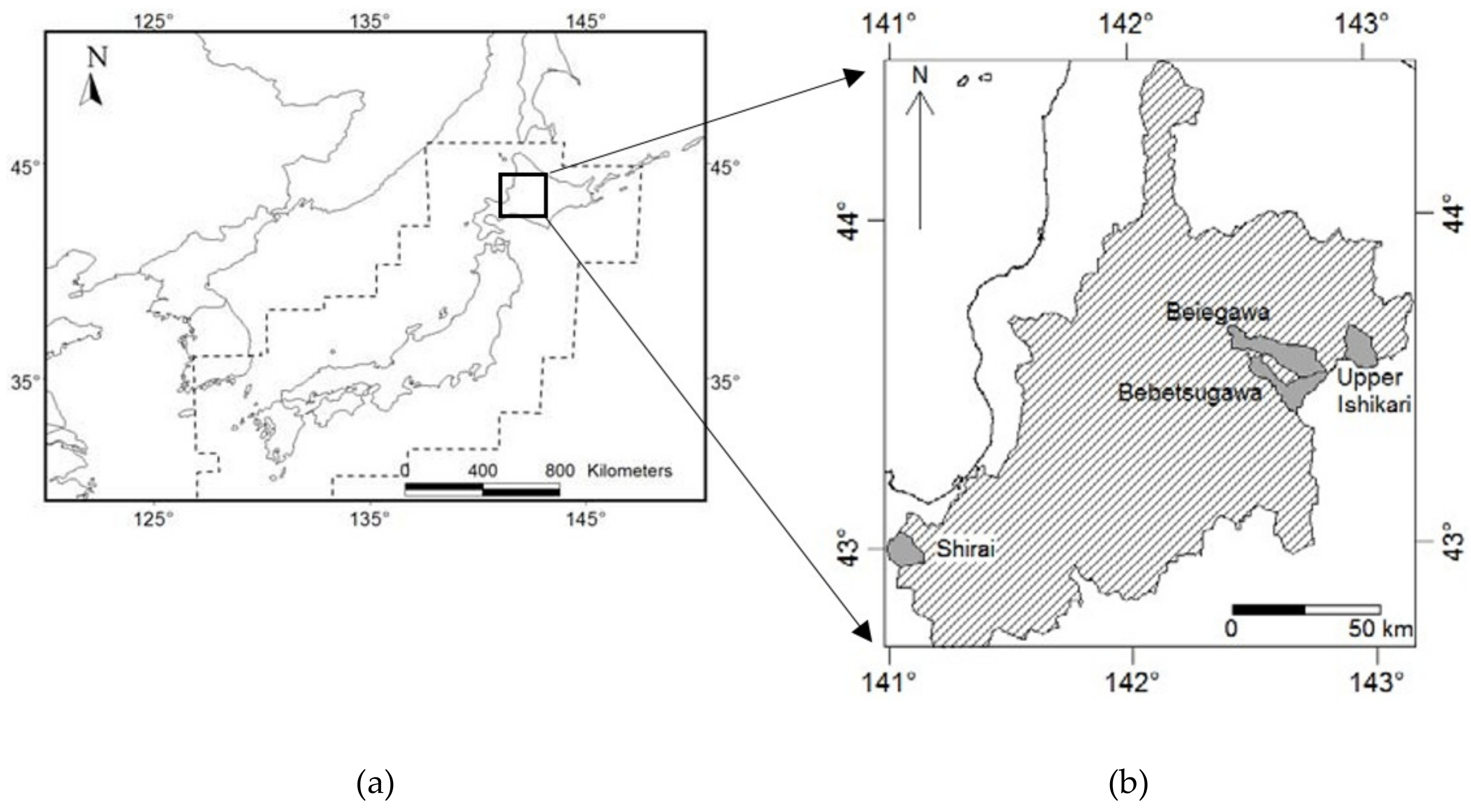
We estimated river flow in the Ishikari River basin, which is located on Hokkaido Island, Japan. However, we only compared flash flooding in four gauged catchments situated in the Ishikari River basin: Shirai (area: 91.40 km2), Bebetsugawa (area: 200.8 km2), Beiegawa (area: 131.5 km2), and Upper Ishikari (area: 113 km2) (see Figure 2). Data for the year 2010 were used for the MATSIRO data-forcing preparation process.
This area is mostly dominated by sedimentary rocks and volcanic rocks. Sedimentary rock includes mudstone, alteration mudstone and sandstone, gravel, sand, and clay. The volcanic rocks generally consist of andesitic rocks, volcanic breccia, and tuff breccia. The terrain of the study area is characterized mainly by small relief mountains, rugged mountains, flat alluvial valleys, and large undulating hills. The dominant land use in the western Hokkaido region is forest, agricultural land including paddy fields, wasteland, and settlements.
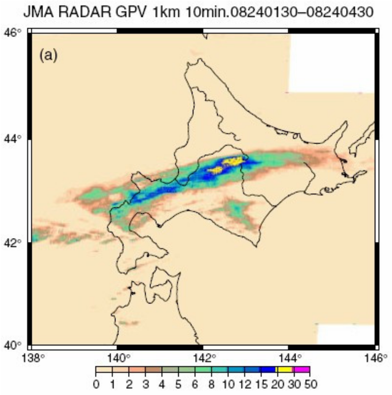
Over 23–24 August 2010, it was reported that a storm event attacked the center of Hokkaido Island from midnight until early morning [16]. The amount of rainfall reported by The Sapporo District Meteorological Observatory was 42 mm h−1. The heavy rainfall over the Ishikari river basin caused floods and landslides in several places. Two people were reported to have died in this disaster. This rainfall is known as line-shape rain bands (LRB), due to its specific spatial distribution of rainfall which makes an elongated line configuration over the region. Figure 3 shows the LRB over Hokkaido Island which is configured from 3-h average rainfall intensity derived by C-band AMeDAS rainfall radar on 24 August 2010 at 01:30–04:30 UTC (Universal Time Coordinated). That figure clearly shows a horizontally elongated rain band in the middle of Hokkaido Island, in which the heaviest rain is centered on the island.

2.3. Data Preparation and Processing

Since we employed many different types of data with different spatial resolutions and map projections, we performed pre-processing on the data by aggregating, spatial resampling (dis-aggregating), spatial interpolation techniques, and geo-referencing so as to they shared the same spatial resolution and projection. However, the impact of such pre-processing to the result, as well as the uncertainty, was not discussed in this paper, because they were considered as another issue. Table 1 briefly summarizes the data used in this study, including their source and pre-processing.
Several atmospheric data forcing for MATSIRO, such as precipitation, wind velocity, atmospheric temperature, atmospheric humidity, atmospheric pressure, downward radiation (infrared and visible), and cloud coverage, were acquired from various data sources. Wind velocity, atmospheric temperature, atmospheric humidity and atmospheric pressure were acquired from the AMeDAS observation network. The data had been prepared by conducting spatial interpolation of the corresponding value based on the observation point location. The longwave and shortwave downward radiation (infrared and visible) were derived from CERES sensors.
MODIS data were used to acquire land surface parameters in MATSIRO. Several MODIS-based data products are relevant as MATSIRO data input: leaf area index (MCD15A3), surface albedo (MCD43B3), and land cover type (MCD12Q1). Because these data are mainly delivered in the Hierarchical Data Format (HDF), which is not compatible with the MATSIRO, they were converted into plain binary format.
MATSIRO uses some topographical parameters, such as the surface slope and the standard deviation of altitude in a grid cell. These parameters can be extracted from a DEM analysis of SRTM-DEM data. Suppose the surface function of DEM is defined as z = f(x,y), where x and y are the grid location of the elevation z. The first derivative in the x and y directions is respectively defined as fx = df/dx and fy = df/dy. The slope angle is calculated as:
β s = Arctan f x 2 + f y 2
The standard deviation of subgrid topography in the grid box can be calculated using a standard deviation function during the aggregation process from the grid size of 90 m × 90 m to 1 km × 1 km. Another contribution of SRTM-DEM information into MATSIRO is related to runoff routing processes; this is made possible by implementing the TRIP to generate the river flow direction and river flow accumulation.
Rainfall forcing data for June–September 2010 were estimated from MTSAT data. A statistical model using the MTSAT 10.8 µm channel data was implemented to estimate rainfall. A cloud type classification based on the MTSAT split window was implemented to detect Cumulonimbus (Cb) cloud [17]. The atmospheric environmental conditions, that is, atmospheric vertical instability and the availability of precipitable water vapor that sustains Cb cloud development, were taken into account during the rainfall estimation process. Particularly for the convective rain, the statistical model was combined with the precipitable water and atmospheric vertical instability [7]. Because the estimated rainfall output preserved the native resolution of the MTSAT image (a grid of approximately 5 km), a statistical downscaling method was conducted to convert the data into a grid size of 1 km; the estimated rainfall from the MTSAT satellite was downscaled with the observed rainfall (hereafter, MTSAT downscaled).
The downscaling process combines the advantages of those two rainfall data capture systems. Rain gauge observations are the only direct source of rainfall data. However, these data are limited due to lack of distribution, particularly in remote areas. Satellite observations are indirect by nature, but they provide very good spatial coverage. By merging the benefits of these systems, the combined result is expected to be improved accuracy, coverage, and resolution [18]. Discrepancies between the satellite-based rainfall estimation and direct observations from rain gauges can be reduced during the downscaling process through bias correction, which is based on: (i) additive; and (ii) multiplicative methods that are applied hourly to each station. The additive bias correction ( r r + ) and multiplicative bias correction ( r r * ) are respectively defined as [18]:
r r + = r r s a t + ( r r o b s i r r s a t i ) ¯
r r * = r r × s a t r r o b s i r r s a t i ¯
The first term in both equations is the satellite-based rainfall estimation. The second terms in Equation (2),(3) represent, respectively, the mean bias (represented by the bar) and both the additive and multiplicative biases between the observed and estimated rainfall for each station (denoted by superscript i). The procedure for performing statistical downscaling is as follows. The observed rainfall is interpolated using the inverse distance weight method on a 1-km grid size, with a limiting distance of approximately 10 km. The satellite-based rainfall is disaggregated from a grid resolution of 5 km to 1 km. Next, the difference between additive or multiplicative is calculated: the means of both the additive and multiplicative biases for each station can be calculated by applying a 3 × 3 summation filter, divided by the number of grid points containing the bias value. The downscaled bias-corrected rainfall can be calculated using Equation (2),(3) for the additive and multiplicative values accordingly. Here, we selected one particular bias correction method for each point grid based on the minimum difference between the bias-corrected rainfall and the observed rainfall. For grid points outside the limiting distance of the interpolation, the original estimated rainfall was assigned.
Three simulations were performed to estimate the river flow using MATSIRO; these are summarized in Table 2. A simulation using rainfall forcing data from the AMeDAS observation was conducted for 1 January–31 December 2010. This simulation generated a so-called ‘restart file’, which is the initial condition of the land surface hydrological condition for each time-step. The other simulations (MLIT and MTSAT downscaled rainfall) were conducted using the current restart file, but only during the period of boreal summer (1 June–30 September 2010). This is because the flash flood events mainly occurred during this period of summer. The estimated river flow was extracted from the river flow distribution at the outlet of the catchment and was finally compared with the observed discharge for August 2010.

3. Results and Discussion

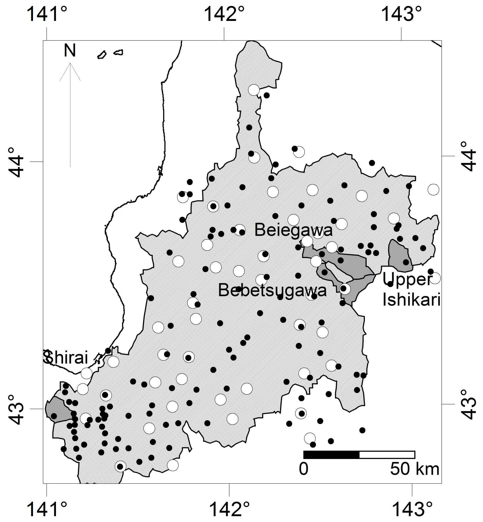
First, the performance of the downscaled MTSAT and AMeDAS rainfall observations was demonstrated by comparison with the MLIT rainfall observations. We selected MLIT rainfall as the benchmark because this includes a denser rainfall network than AMeDAS, particularly in mountainous regions. Figure 4 presents the distribution of the AMeDAS rainfall network (white dots) and the MLIT rainfall network (black dots). Because MLIT data were characterized by a denser station network over the Ishikari River basin (spacing of approximately 10 km) compared with AMeDAS (spacing of approximately 20 km), it is likely more accurate than the other rainfall measurements, and likely represents the spatial distribution of rainfall more accurately.
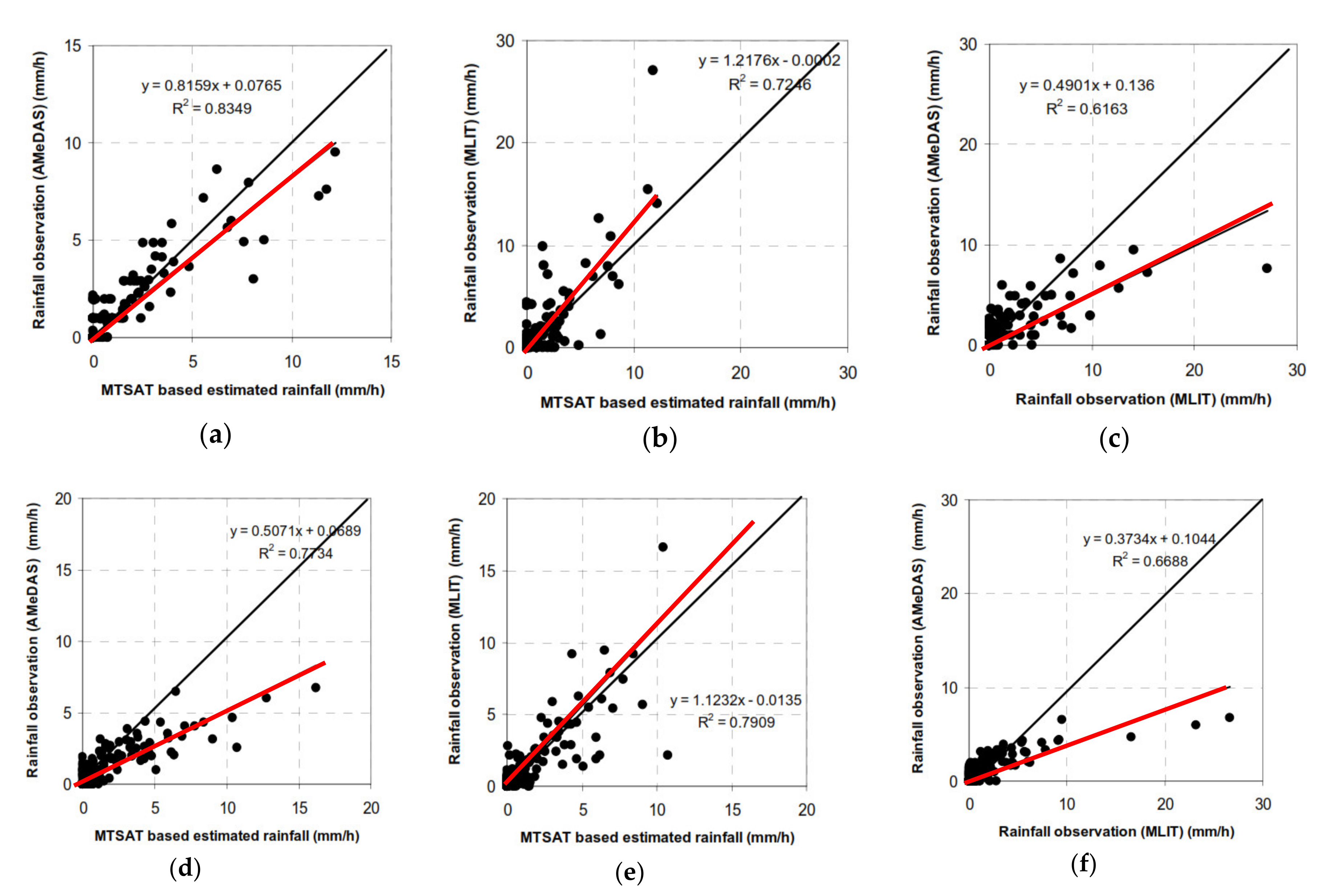
The area average of rainfall from MTSAT downscaled and observed rainfall from both AMeDAS and MLIT was calculated for the Shirai and Bebetsugawa catchment areas. Graphical comparison was conducted by plotting them in a scatter plot as shown in Figure 5. By considering that figure in detail, Figure 5a, 5b and 5c successively show the scatter plot of MTSAT downscaled vs. AMeDAS rainfall, MTSAT downscaled vs. MLIT rainfall, and AMeDAS rainfall vs. MLIT rainfall for Shirai catchment. The similar scatter plots are created for Bebetsugawa catchment such as shown in Figure 5d, 5e and 5f. Those figures indicate that the best relationship is shown by MTSAT downscaled vs. MLIT rainfall compared to others. If it is assumed that MLIT rainfall is showing more accurate rainfall distribution due to having a denser network than the others, those scatter plots suggest that the use of MTSAT downscaled is showing reasonably better in representing rainfall than if only using AMeDAS rainfall. It is suggested that use of MTSAT estimated rainfall downscaled by AMeDAS is more recommended, it is more recommended to especially in the mountainous ungauged region, instead of using only AMeDAS observations.
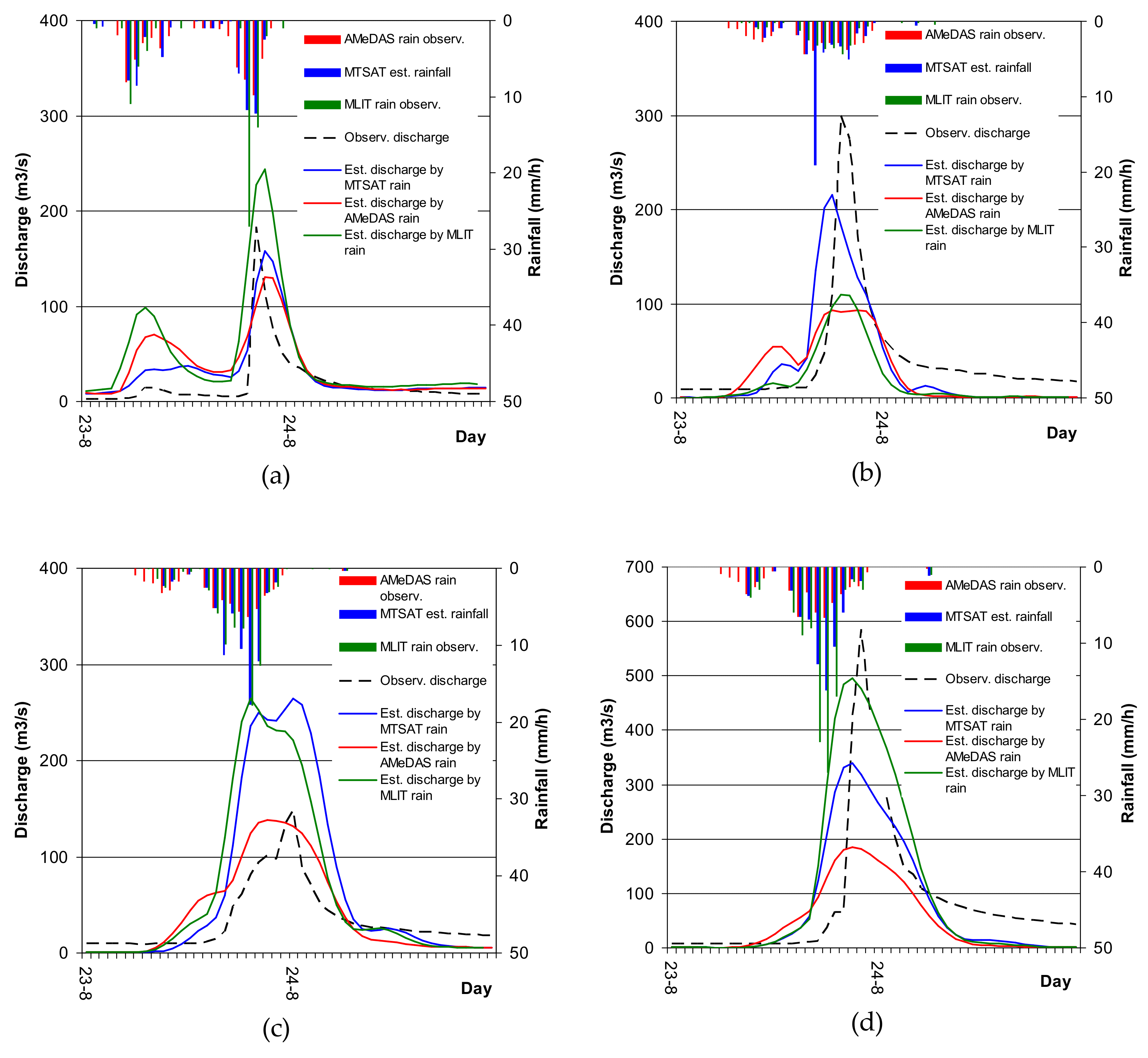
A comparison of the hourly estimated river discharge as the result of river flow simulations using MATSIRO with the observed discharge can be presented in two ways: graphical comparison, and comparison of statistical performance by measuring correlation, bias, and root mean square (RMS) [18]. Since the objective of this study is to simulate a flash flood by using several types of rainfall forcing, for the purpose of comparison we only consider a flash flood event which occurred during a heavy rainfall event over 23 and 24 August 2010. This heavy rainfall event has already been explained in the previous section.
Figure 6a–d show the peak discharge hydrographs for the Shirai, Bebetsugawa, Upper Ishikari, and Beiegawa rivers, respectively. These flood events are classified as flash floods due to the short time to peak discharge and the relatively high peak discharge. From the Figure 6, it can be examined that the time to peak of discharge is about 1 to 6 h and peak of discharge which is detected by simulation is about 1 to 2 h earlier than the observation. The graphical comparison of the river flow simulations demonstrate that estimating discharge using MLIT rainfall is the best in showing the peak discharge pattern, especially for the Shirai and Bebetsugawa rivers. This result is due to the fact that MLIT has a relatively dense rainfall network compared with AMeDAS, so it can more accurately represent the rainfall distribution. The second-best method for estimating discharge is using downscaled MTSAT, and the worst is using AMeDAS rainfall. These results are consistent with the previous finding, with regard for providing flash flood information about ungauged catchments, the use of downscaled MTSAT for rainfall forcing is more accurate than solely using AMeDAS rainfall. Since most areas have faced problem in lacking rainfall networks, the downscaled MTSAT results may be useful to overcome this problem. MTSAT is able to represent the rainfall distribution well, but it is less accurate in predicting the amount of rainfall. This limitation was improved by adjusting bias based on observed rainfall, even when these data are acquired with sparse station distribution.
The graphical comparison was confirmed by a statistical performance calculation, as presented in Table 3. This statistics are calculated only for the period of the flash flood event, that is, 23 and 24 August 2010. Numbers that have been bolded indicate the most accurate statistics. The results suggest that discharge simulated using downscaled MTSAT is reasonably comparable with MLIT rainfall-based simulated discharge, and that both of these methods are much better than using AMeDAS rainfall alone as input forcing.

4. Conclusions

A river flow simulation was conducted using the MATSIRO land surface model in the Ishikari River basin. Input forcing data were a combination of direct observations from the AMeDAS network and data derived from remote sensing. A statistical downscaling procedure was applied to MTSAT satellite-based rainfall estimation by merging these data with the interpolated AMeDAS rainfall. We compared the MTSAT downscaled and AMeDAS interpolated rainfall with the MLIT rainfall, which we assumed would represent the rainfall distribution more accurately than AMeDAS due to the denser station distribution. The comparison revealed that downscaled MTSAT is reasonably comparable with MLIT rainfall and is better than using AMeDAS data alone. The river flow simulations for the four catchment areas in the Ishikari basin demonstrate that using MLIT rainfall to estimate peak discharge provides more accurate results than the other methods. However, the downscaled MTSAT is better as input forcing in a physically based model, because its accuracy is roughly comparable with relatively dense rain gauge networks such as the MLIT. Moreover, many regions have sparse rain gauges, and this challenge can be overcome by merging these data with MTSAT rainfall estimation.

Author Contributions

D.P.Y.S. and T.J.Y. designed the research; D.P.Y.S. performed the analyses and wrote the paper. All authors have read and agreed to the published version of the manuscript.

Funding

This study was partially supported by the Research Program on Climate Change Adaptation, Ministry of Education, Culture, Sports, Science and Technology, Japan (SI-CAT/MEXT).

Conflicts of Interest

The authors declare no conflict of interest.

References

  1. Yousef, A.M.; Pradhan, B.; Hassan, A.M. Flash flood risk estimation along the St. Katherine road, southern Sinai, Egypt using GIS based morphometry and satellite imagery. Environ. Earth Sci. 2011, 62, 611–623. [Google Scholar] [CrossRef]
  2. Alfieri, L.; Thielen, J.; Pappenbeger, F. Ensemble hydro-meteorological simulation for flash flood early detection in Southern Switzerland. J. Hydrol. 2012, 424, 143–153. [Google Scholar] [CrossRef]
  3. Saharia, M.; Kirstetter, P.E.; Vergara, H.; Gourley, J.J.; Hong, Y.; Giroud, M. Mapping Flash Flood Severity in the United States. J. Hydrometerol. 2017, 18, 397–411. [Google Scholar] [CrossRef]
  4. Kim, E.S.; Choi, H.I. Estimation of the relative severity of floods in small ungauged catchments for preliminary observation on Flash flood preparedness: A case study in Korea. Int. J. Environ. Res. Public Health 2012, 9, 1507–1522. [Google Scholar] [CrossRef] [PubMed] [Green Version]
  5. Haile, A.T.; Rientjes, T.; Gieske, A.; Gebremichael, M. Multispectral remote sensing for rainfall detection and estimation at the source of the Blue Nile river. Int. J. Appl. Earth Obs. Geoinf. 2010, 12, S76–S82. [Google Scholar] [CrossRef]
  6. Kinoti, J.; Su, Z.; Woldai, T.; Maathuis, B. Estimation of spatial-temporal rainfall distribution using remote sensing techniques: A case study of Makanya catchment, Tanzania. Int. J. Appl. Earth Obs. Geoinf. 2010, 12, S90–S99. [Google Scholar]
  7. Suseno, D.P.Y.; Yamada, T.J. The role of GPS precipitable water vapor and atmospheric vertical stability index in the statistically-based rainfall estimation using MTSAT data. J. Hydrometerol. 2013, 14, 1922–1932. [Google Scholar] [CrossRef] [Green Version]
  8. Wardah, T.; Abu Bakar, S.H.; Bardosy, A.; Maznorian, M. Use of geostationary meteorological satellite images in convective rain estimation for flash-flood forecasting. J. Hydrol. 2008, 356, 283–298. [Google Scholar] [CrossRef]
  9. Kuligowski, R.J.; Li, Y.; Hao, Y.; Zang, Y. Improvements to the GOES-R Rainfall Rate Algorithm. J. Hydrometerol. 2016, 17, 1693–1704. [Google Scholar] [CrossRef]
  10. Yang, J.; Zhang, Z.; Wei, C.; Lu, F.; Guo, Q. Introducing the New Generation of Chinese Geostationary Weather Satellites Fengyun-4. Bull. Amer. Meteor. Soc. 2017, 17, 1637–1658. [Google Scholar] [CrossRef]
  11. Song, H.J.; Lim, B.; Joo, S. Evaluation of Rainfall Forecasts with Heavy Rain Types in the High-Resolution Unified Model over South Korea, Wea. Forecasting. 2019, 34, 1277–1293. [Google Scholar] [CrossRef]
  12. Takata, K.; Emori, S.; Watanabe, T. Development of the minimal advance treatments of surface interaction and runoff. Glob. Planet. Chang. 2003, 38, 209–222. [Google Scholar] [CrossRef]
  13. Mishra, A.K. Effect of rain gauge density over the accuracy of rainfall: A case study over Bangalore, India. SpringerPlus 2013, 2, 311. [Google Scholar] [CrossRef] [PubMed] [Green Version]
  14. Oki, T.Y.; Sud, C. Design of Total Runoff Integrating Pathways (TRIP)-A global river channel network. Earth Interact. 1998, 2, 1–36. [Google Scholar] [CrossRef]
  15. Koirala, S.; Yamada, H.; Yeh, P.; Oki, T.; Hirabayashi, Y.; Kanae, S. Global Simulation Of Groundwater Recharge, Water Table Depth, And Low Flow Using A Land Surface Model With Groundwater Representation. Annu. J. Hydraul. Eng. 2012, 56. [Google Scholar] [CrossRef] [Green Version]
  16. Yamada, T.J.; Sasaki, J.; Matsuoka, N. Climatology of line-shaped rainbands over northern Japan in boreal summer between 1990 and 2010. Atmos. Sci. Lett. 2012, 13, 133–138. [Google Scholar] [CrossRef]
  17. Suseno, D.P.Y.; Yamada, T.J. Two-dimensional, threshold-based cloud type classification using MTSAT data. Remote Sens. Lett. 2012, 3, 737–746. [Google Scholar] [CrossRef] [Green Version]
  18. Vila, D.A.; Goncalves, L.G.; Toll, D.L.; Rozante, J.B. Statistical Evaluation of Combined Daily Gauge Observation and Rainfall Satellite Estimates over Continental South America. J. Hydrometeorol. 2009, 10, 533–543. [Google Scholar] [CrossRef]
Figure 1. The structure and calculation flow in the Minimal Advance Treatments of Surface Interaction and Runoff (MATSIRO) (reproduced from Takata et al., 2003). LC, land cover type; SOIL, soil type; LAI, leaf area index; GALB, ground albedo; SLOPE, surface mean slope; ELEVSTD, standard deviation of altitude in a grid cell; U, wind velocity; T, atmospheric temperature; Q, humidity; P, pressure; RD, downward radiation.
Hydrology 07 00009 g001
Figure 2. (a) The location of study area in the islands of Japan; (b) Ishikari river basin, Hokkaido bounded as shaded area. The grey areas represent Shirai, Bebetsugawa, Beiegawa, and Upper Ishikari river sub-basins.
Hydrology 07 00009 g002
Figure 3. Spatial distribution of 3-h average rainfall intensity (mm/h) from derived from C-band AMeDAS rainfall radar over Hokkaido Island on 24 August 2010 at 01:30–04:30 UTC [16].
Hydrology 07 00009 g003
Figure 4. The locations of sub-catchments (grey shaded polygon) that are situated inside the Ishikari river basin (hatched polygon). The dots show the distribution of the AMeDAS rainfall network (white dots) and the MLIT rainfall network (black dots).
Hydrology 07 00009 g004
Figure 5. Scatter plot of catchment average hourly rainfall; (a,d) MTSAT based rainfall estimation vs. observed rainfall by AMeDAS, (b,e) MTSAT based rainfall estimation vs. observed rainfall by MLIT, and (c,f) observed rainfall by AMeDAS vs. observed rainfall by MLIT from August 2010 for (ac) Shirai river catchment and (df) Bebetsugawa river catchment.
Hydrology 07 00009 g005
Figure 6. Peak discharge during a heavy rainfall event on 23–24 August 2010 at the catchment outlets of (a) Shirai; (b) Upper Ishikari; (c) Beiegawa and (d) Bebetsugawa river.
Hydrology 07 00009 g006
Table 1. Atmospheric and land surface parameters sources and preprocessing. AMeDAS, Automated Meteorological Data Acquisition System; MLIT, Ministry of Land, Infrastructure and Transportation; MTSAT, Multi-purpose Transport Satellite; MODIS, Moderate Resolution Imaging Spectroradiometer; SRTM-DEM, Shuttle Radar Topographic Mission Digital Elevation Model; CERES, Cloud and Earth’s Radiant Energy System.
ParametersSourceSpatial ResolutionTemporal ResolutionData Preprocessing
Atmospheric Parameters
Precipitation (Rainfall)AMeDAS observationPoint observation1 hSpatial interpolation
MLIT observation1 hSpatial interpolation
Remote sensing (MTSAT based estimation)Point observation1 hSpatial interpolation and statistical downscaling
5 km downscaled into 1-km
WindAMeDAS observationPoint observation1 hSpatial interpolation
Atmospheric TemperatureAMeDAS observationPoint observation1 hSpatial interpolation
Atmospheric PressureAMeDAS observationPoint observation1 hSpatial interpolation
Atmospheric Relative HumidityAMeDAS observationPoint observation1 hSpatial interpolation
Cloud coverJMA Mesoscale Model25 km3 hSpatial Resampling
Shortwave downward radiationRemote sensing (CERES)20 km~12 hSpatial Resampling
Longwave downward radiationRemote sensing (CERES)20 km~12 hSpatial Resampling
Land surface parameters
Land useRemote Sensing (MODIS)1 kmyearlyGeo-referencing and spatial resampling
Surface slopeRemote Sensing (SRTM-DEM)90 m-Spatial aggregation and DEM processing
Standard deviation of surface topographyRemote Sensing (SRTM-DEM)90 m-Spatial aggregation and DEM processing
Flow directionRemote Sensing (SRTM-DEM)90 m-Spatial aggregation and DEM processing
Flow accumulationRemote Sensing (SRTM-DEM)90 m-Spatial aggregation and DEM processing
Surface AlbedoRemote Sensing (MODIS)1 km16 daysGeo-referencing
Leaf Area IndexRemote Sensing (MODIS)1 km8 daysGeo-referencing
Soil textureFAO digital soil map of the worldVector based at 1:5,000,000 scale-Geo-referencing and spatial resampling
Table 2. Summary of river flow simulations using MATSIRO.
Simulation NameTime DurationRainfall Data Forcing
Simulation I1 January–31 December 2010AMeDAS rainfall observation
Simulation II1 June–30 September 2010MLIT rainfall observation
Simulation III1 June–30 September 2010MTSAT downscaled
Table 3. Comparison of the performance of simulated vs. observed river discharge during flash flood event on 23 and 24 August 2010.
Catchment’s NameSimulation ISimulation IISimulation III
CorBias (m3/s)RMS (m3/s)CorBias (m3/s)RMS (m3/s)CorBias (m3/s)RMS (m3/s)
Shirai0.688.720.80.749.822.80.756.515.5
Upper Ishikari0.61−2.716.90.71−4.914.10.67−0.719.0
Beiegawa0.695.320.90.7511.737.90.7611.136.7
Bebetsugawa0.512.132.10.708.441.30.607.136.9