Abstract
This study proposes a new dense membrane for selectively separating CO2 and O2 at high temperatures and simultaneously producing syngas. The membrane consists of a cermet-type material infiltrated with a ternary carbonate phase. Initially, the co-doped ceria of composition Ce0.9Zr0.05Y0.05O2−δ (CZY) was synthesized by using the conventional solid-state reaction method. Then, the ceramic was mixed with commercial silver powders using a ball milling process and subsequently uniaxially pressed and sintered to form the disk-shaped cermet. The dense membrane was finally formed via the infiltration of molten salts into the porous cermet supports. At high temperatures (700–850 °C), the membranes exhibit CO2/N2 and O2/N2 permselectivity and a high permeation flux under different CO2 concentrations in the feed and sweeping gas flow rates. The observed permeation properties make its use viable for CO2 valorization via the oxy-CO2 reforming of methane, wherein both CO2 and O2 permeated gases were effectively utilized to produce hydrogen-rich syngas (H2 + CO) through a catalytic membrane reactor arrangement at different temperatures ranging from 700 to 850 °C. The effect of the ceramic filler in the cermet is discussed, and continuous permeation testing, up to 115 h, demonstrated the membrane’s superior chemical and thermal stability by confirming the absence of any chemical interaction between the material and the carbonates as well as the absence of significant sintering concerns with the pure silver.
1. Introduction
The intensive usage of energy by industrial, households, and transportation has considerably boosted atmospheric greenhouse gas emissions. Hence, new technology is needed to reduce anthropogenic carbon dioxide and other pollutants coming from fossil fuel combustion [1,2]. Research in chemistry and materials science has created numerous efficient CO2 sorbents, including porous materials, solid sorbents, and systems based on organic solvents, such as ionic liquids, amines, and, more recently, the so-called deep eutectic solvents [2,3]. However, notwithstanding their advances, these systems still confront regeneration capacity, operating temperatures, high costs, and corrosion issues, which limit their usage to industrial-scale CO2 capture [3,4].
Inorganic membranes can help the development of greener and more efficient energy production [5]; for example, membrane reactors that integrate CO2 separation and conversion [6]. Membranes based on molten carbonate phases and exhibiting ionic or electrical properties have been studied to reduce CO2 emissions [6,7,8], such as metallic dual-phase membranes fabricated using porous stainless steel or silver as supports and infiltrated with different molten carbonate mixtures [9,10,11]. These metallic-based systems showed concurrent permselectivity for CO2 and O2. The generally accepted mechanism for CO2 transport through these membranes involves the surface electrochemical interaction between CO2 molecules, oxygen, and electrons provided by the metallic support (Reaction (1)) to form and eventually transfer carbonate ions through the membrane bulk via the molten phase [9]. Figure 1 shows that the membrane’s downstream side releases molecular carbon dioxide and oxygen because Reaction (1) is reversible.
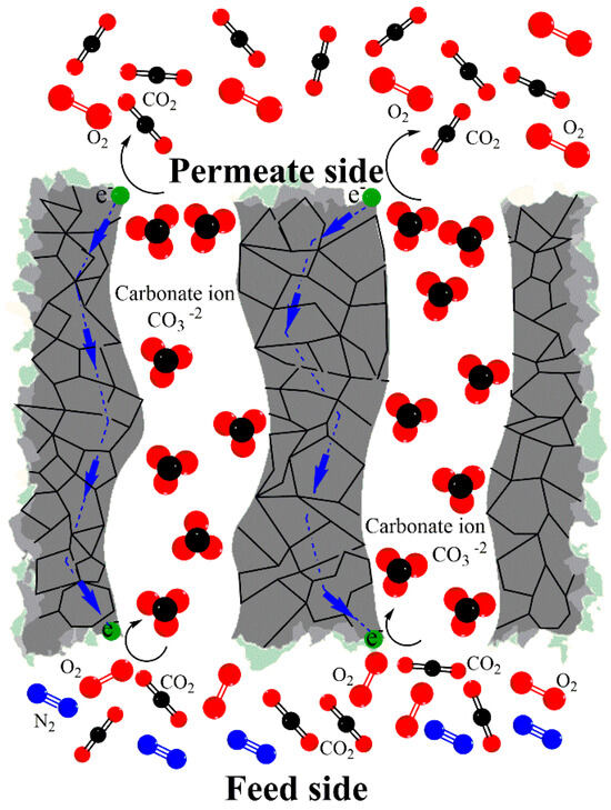
Figure 1.
Schematic showing the selective separation of CO2 and O2 across a metal–carbonate membrane system at elevated temperatures.
Under temperature and O2 differential partial pressure and long-term operating, it has been observed that several factors may reduce CO2 permeability, including the reactivity of the membrane metal support and its densification at high temperatures [9,10,12]. Consequently, improving metallic membranes’ chemical and thermal stability has become a research challenge [13,14,15]. Recently, cermets made of a silver matrix and a ceramic phase as filler have been proposed to enhance the membrane performance [16,17].
Al2O3 and ZrO2 layers were deposited on Ag porous supports to improve silver wettability against molten carbonates and inhibit coarsening during high-temperature operation [13,15]. Ag-modified α-Al2O3-supported membranes were made by electroless plating and direct infiltration; this processing approach avoids using a bulk silver skeleton that is prone to sintering at elevated temperatures; instead, the silver is only located at the surface of the porous alumina support [14]. Recently, it was proposed to incorporate Ag into Al2O3 support’s pore channels by promoting the self-assembling of silver dendritic structures. This strategy significantly reduces the amount of silver required for the membrane fabrication and exhibits an impressive flow of 1.25 mL·min−1·cm−2 at 650 °C [14].
Unlike a surface modification, the ceramic can be added as a filler into a silver matrix to create a cermet. For example, LiAlO2/Ag and Ce0.8Sm0.2O2−δ/Ag cermets have been produced by ball milling and subsequent infiltration with carbonates [16,17]. Certainly, the type and amount of ceramic can enhance the wettability of the solid phase against the carbonate phase and avoid its sinterability under operating conditions, but the filler can also be carefully selected to promote extra oxygen transport or to inhibit carbon deposition on the membrane surface during reforming reactions [17].
Due to its separation properties as well as the temperature range of operating, carbonate-based dual-phase membrane reactors have been reported for the separation and conversion of CO2 and O2; for example, by the oxidative dry reforming process that implies a combination of CO2 reforming (Reaction (2)) and the partial oxidation of CH4 (Reaction (3)) [16,18,19]. It leads to syngas (H2 + CO) production, a primary raw material in the chemical industry, to manufacture several chemicals, such as methanol, ammonium, and synthetic liquid fuels [20,21].
The present study describes the fabrication, performance, and stability of a membrane made of a Ce0.9Zr0.05Y0.05O2−δ/Ag (CZY/Ag) cermet infiltrated with a ternary molten carbonate mixture. The ceramic filler is a co-doped ceria, a type of material with well-known oxygen ionic conducting properties. Furthermore, the proposed membrane has been evaluated not only for the selective separation of CO2 but also as a membrane reactor by coupling it in the oxy-CO2 reforming of methane to valorize CO2 through syngas production. It is envisaged that incorporating co-doped ceria, which exhibits outstanding properties such as oxygen storage capacity, thermal stability, and chemical stability against molten carbonates, into the silver-based cermet would help the stability of the derived membrane by tackling some common issues observed during the long operating condition of pure silver-based membranes such as sintering, carbonates loss, and even methane cracking [16,17]. The results obtained are promising and clearly show the excellent properties of the membrane and its application as a membrane reactor. Moreover, using ceramic material as a filler in the silver matrix of the cermet can help solve the cost issue of using pure Ag as a support material.
2. Materials and Methods
2.1. Synthesis of the CZY/Ag Powder
Initially, the sample with formula Ce0.9Zr0.05Y0.05O2−δ was synthesized by a solid-state reaction method. ZrO2 (99.6% purity, TOSOH, Tokyo, Japan), Y2O3 (99.9% purity, Sigma-Aldrich, St. Louis, MO, USA), and CeO2 (99.9% pure, Sigma-Aldrich) ceramic powders were used as the starting raw materials. A stoichiometric amount of each powder was weighed, mixed, and ball-milled in ethanol for 24 h using ceramic balls of 3 mm diameter as the grinding medium. Then, the obtained mixtures were dried and manually ground in an agate mortar to be calcined at 1350 °C for 3 h. This process was repeated 3 times to obtain a complete solid solution of the starting single oxides without secondary phases or residues of the reactants. Supplementary CZY synthesis and characterization data are provided (Figure S1). The powder obtained was labeled as CZY. Then, to fabricate the CZY/Ag cermets, the CZY ceramic powder was mixed with silver powders of 400 mesh (99.9%, Stannum de México, Ciudad de México, Mexico) and ball-milled in a Spex-Mixer/Mill apparatus from Chemplex Instruments (Palm City, FL, USA). The grinding media was ceramic balls of 9 mm in diameter, and the weight ratio of balls to powders was 10 to 1. The powders were milled for 15 min to obtain cermet powders exhibiting a CZY:Ag 30:70 volume ratio.
2.2. Fabrication of Cermet-Based Dense Membranes
The CZY/Ag cermet powders were processed by uniaxially pressing to form disk-shaped supports. Then, the green supports were sintered at 900 °C for 20 h in air using a heating ramp of 1 °C/min. Then, obtained porous supports were directly infiltrated with a ternary mixture of molten carbonates (Li2CO3/Na2CO3/K2CO3) to form dense membranes. Fabrication and infiltration steps were carried out following laboratory procedures reported by our research group [17]. After infiltration, the carbonate excess that solidified on the membrane surface was gently removed by polishing. The membrane’s average thickness was accurately measured using adigital micrometer model H-2780 (Mitutoyo, Kawasaki, Japan) with a precision of 0.01 mm. Hence, a microscopy analysis was performed to provide valuable information about the membrane’s thickness and microstructural features, such as the presence of cracks or pinholes (non-infiltrated pores) defects. Figure S2 shows the cross-section image of the infiltrated and polished membrane obtained by conventional optical microscopy; the membrane’s average thickness was measured as 1.34 mm using the ImageJ version 14.1 software. Finally, it is emphasized that the ceramic phase in the composite was incorporated, considering that it constitutes only a volume fraction of 0.3. This is to avoid going beyond the percolation threshold of the conductive phase. In order to prove that the amount of ceramic used does not affect the silver’s conduction properties, its conductivity value (1/r) was calculated using a DC-resistant tester apparatus model CKT3544 (Chuangkai Electronic Co., Changzhou, China), which operates in a measurement range of 0.1 μΩ–3.3 MΩ.
2.3. Synthesis of the Reforming Catalyst
Due to its already-known catalytic activity and stability properties, a Ni/CeO2 catalyst was selected for the methane reforming process [22]. The catalyst was prepared using the incipient wetness impregnation method and the spray dryer techniques. First, a suspension of CeO2 was prepared by the dispersion of commercial powders and the appropriate amount of Ni (NO3)2⋅6H2O to obtain a catalyst with a composition of 10 wt.% of Ni on CeO2 support. The suspension was fed to a laboratory spray dryer apparatus model ADL311SA (Yamato, Japan). The drying process was performed at 150 °C with air as drying gas. The dried catalyst was calcined at 700 °C for 5 h in an air atmosphere.
2.4. Materials Characterization
Cermet materials (powders and porous disks) were structurally and microstructurally characterized. X-ray diffraction was performed by using a D8-Advanced diffractometer (Bruker, Billerica, MA, USA); the apparatus is equipped with a Cu-Kα radiation source. All samples were measured in the 2θ range from 20 to 80°. A scanning electron microscope model JSM-6400 (JEOL, Tokyo, Japan) was used to analyze the samples’ microstructure, morphology, and elemental composition (EDS technique). The total open porosity of cermets disks (ε) was determined by immersion in water at room temperature, following the Archimedes technique according to the ASTM C-830 [23]. Additionally, samples were characterized by the N2 adsorption/desorption technique using an Autosorb iQ apparatus (Quantachrome, Boynton Beac, FL, USA).
2.5. Permeation Measurements of CO2 and O2
Gas permeation and membrane reactor studies were performed at high temperatures using the permeation equipment Probostat (NORECs, Oslo, Norway)Briefly, the fabricated dense membranes were fixed to a dense alumina tube using a silver O-ring (99% purity) to form a gas seal at high temperatures. The system was enclosed with a larger diameter ceramic tube, and then, the assembly was introduced into a vertical tubular furnace. In the permeation studies, the system was fed with two different gas mixtures of 85/15 and 50/50 vol.% of dry air and CO2 with a total flow rate of 50 mL·min−1 and sweep gas of high-purity Ar to 50 mL·min−1. Additional experiments were performed using a sweep gas to 100 mL·min−1. The feed and sweep gas mixtures were established by using a NORECs gas mixer model FCMix. Permeation readings (CO2 and O2 concentrations, plus the presence of N2 from leakage) were recorded between 700 and 850 °C by using a gas chromatograph model GC-2014 (SHIMADZU, Kyoto, Japan) equipped with a TCD detector and a Carboxen-1010 PLOT capillary column. The permeation area of the membrane was 2.46 cm2. Supplementary data provide a detailed schematization of the membrane reactor arrangement (Figure S3).
2.6. Membrane Reactor Evaluation
A packed catalyst bed was placed about 1 cm underneath the membrane sweep side to perform the oxidative CO2 reforming of methane (OCRM) tests. In this experiment, the downstream side of the membrane reactor was fed with a gas mixture of 10 vol.% of CH4 in argon with a total flow rate of 100 mL∙min−1. Previously to the reaction, the active nickel phase in the catalyst was reduced using a gas mixture of 50 vol.% H2 in argon at 700 °C for 1.5 h. The GC equipment was used to measure the permeated composition. Our previous publications describe similar experimental procedures in more detail [16,17].
3. Results and Discussion
3.1. A Fabrication and Characterization of CZY/Ag Powder and Membrane
CZY ceramic powders were synthesized using the solid-state reaction method. Figure 2 shows the obtained single particles ranging from 0.14 to 0.32 μm, with an average particle size of 0.22 μm. Moreover, EDS analysis shows the homogeneous distribution of both Zr and Y in the sample; these results suggest that the milling and calcination steps promote the homogeneous composition of the material as well as avoid the formation of rigid aggregates, keeping the ultimate particle size in the submicrometric range. These features of the ceramic sample are desirable as the powder acts as a filler in the cermet, which is expected to be well distributed in the Ag matrix. Here, it is essential to mention that the XRD analysis of the CZY powders (Figure S1) yielded a single crystalline phase, i.e., the expected Ce0.9Zr0.05Y0.05O2−δ, wherein Zr and Y form a solid solution with the ceria. The diffraction pattern of the CZY powder was indexed according to the JCPDS card No. 34-0394 in CeO2 with the FCC structure. No other diffraction peaks were observed.
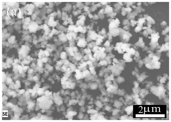
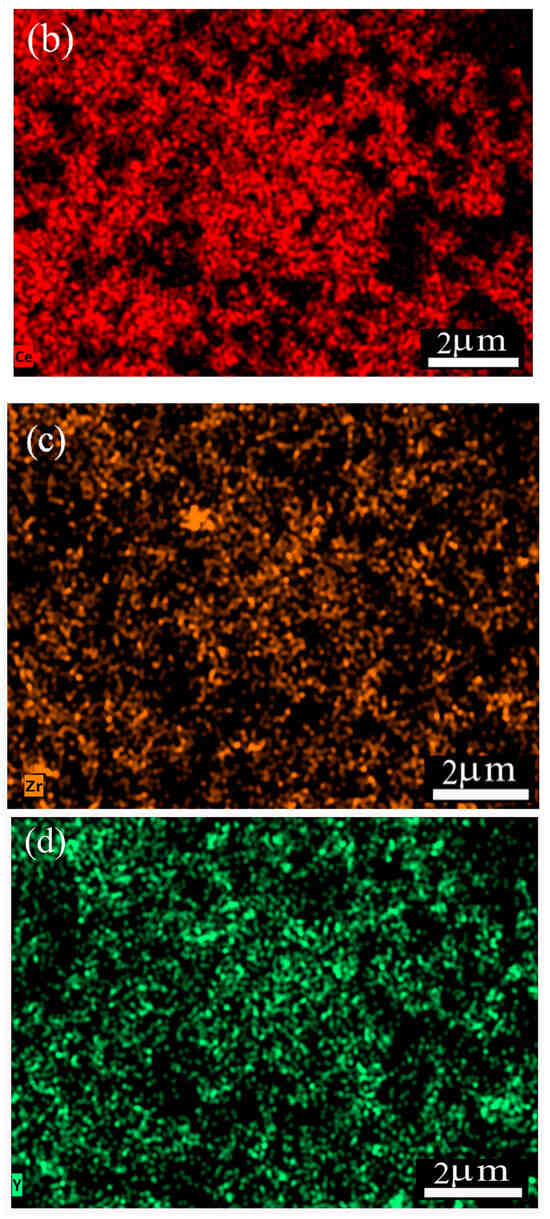
Figure 2.
SEM images and chemical element mapping of CZY powder: (a) CZY powder obtained by milling and calcination, (b) elemental analysis of cerium, (c) zirconium, and (d) yttrium.
Regarding the formation of the cermet-type composites by milling, SEM analysis (Figure 3a) shows the initial morphology of the commercial Ag powders, constituted by spherical and nodular particles; this feature is characteristic of powders obtained by the atomization process. Then, Figure 3b shows that by integrating the CZY ceramic phase as filler and thus forming the CZY/Ag cermet, the powders are composed of aggregates made of individual particles with sizes of about 0.12 μm. These characteristics are remarkable because the average particle size is smaller than the sizes of the initial powders of both the ceramic and metallic phases. Moreover, the milling process promotes the integration of the filler into the metallic matrix and the size reduction in the final powder. Despite the plastic properties of the silver powders, it can be argued that incorporating the hard and brittle ceramic into the metallic matrix enables the comminution process. The short grinding times, which were only 15 min, also prevented the formation of flake-like particles commonly obtained in metal powder exposed to long-term milling processes. Therefore, the milling technique used for cermet formation represents a practical and facile approach that can even be considered a scalable process. The EDS analysis of the sample shows the presence of all the constituent elements in the sample as evidence of the cermet formation (Figure 3d). Additionally, the adsorption/desorption isotherms of CZY, Ag, and cermet powders were recorded. As expected, the results (Figure 3e) reveal certain microstructural changes in porosity and surface area values due to the ball milling process and the composite formation (Table 1).
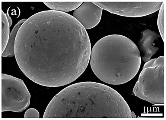
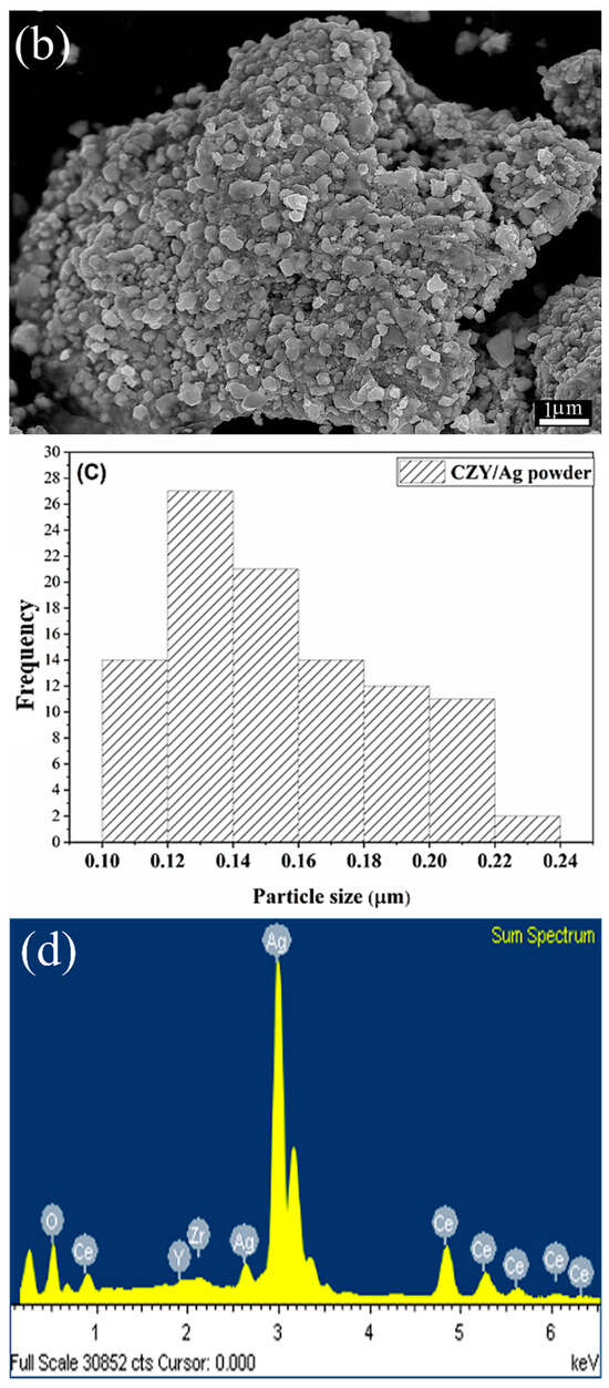
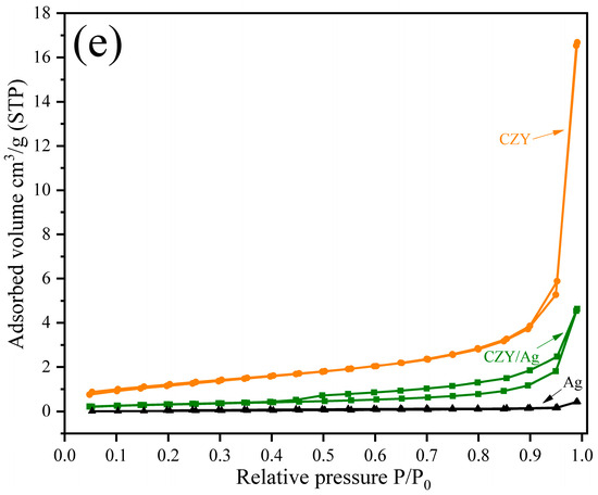
Figure 3.
(a) SEM images of the starting silver powder, (b) CZY/Ag cermet prepared by high-energy milling, (c) particle size distribution of CZY/Ag powder (ultimate particle size), (d) EDS analysis of the cermet, and (e) N2 adsorption/desorption isotherms.

Table 1.
Surface area (SBET) and porosity features of the raw materials and cermet samples.
Figure 4a shows the SEM images of the cross-section of the porous support obtained by pressing and sintering the synthesized cermet powders. The observed open porosity results from the sample’s incipient densification. The total volume of porosity calculated by immersion in water is about 30 vol.%. Moreover, the porosity is highly interconnected as the He permeation test of the support gives a value of 4.6 × 10⁻⁶ mol·m−2·s−1·Pa−1. After infiltration with molten carbonates (Figure 4b), a dense membrane is obtained where the solidified carbonates occupy the support porosity volume. The presence of cracks or holes was not observed; moreover, performing the unsteady-state He permeation test, a significantly reduced permeation of 1.11 × 10⁻¹⁰ mol·m−2·s−1·Pa−1 was observed. In this way, it was verified that the membrane is gas-tight. Ceria is known to exhibit excellent wettability against molten carbonates; therefore, infiltration must be promoted in the cermet.
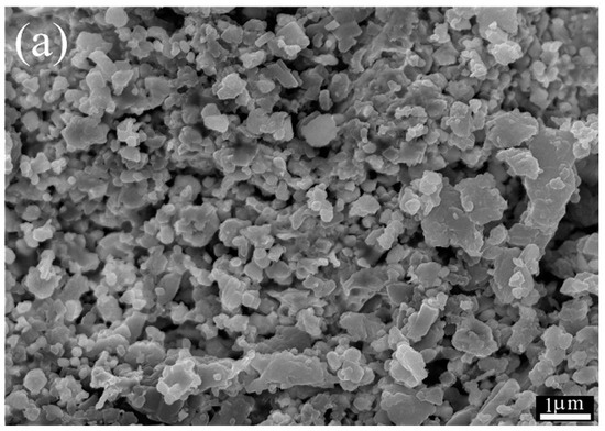
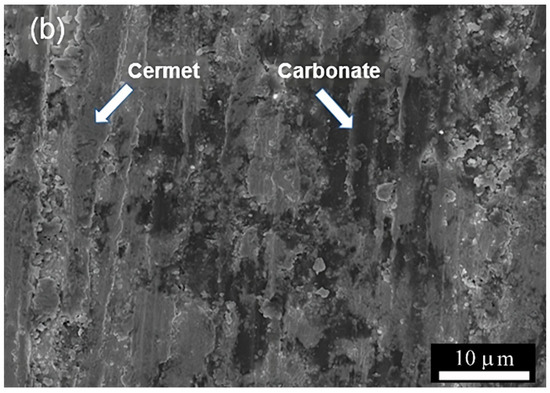
Figure 4.
(a) SEM micrographs of porous cermet support (cross-section) without carbonate and (b) dense membrane after carbonate infiltration.
The conductivity value of the infiltrated membrane was calculated as 2.3 × 10⁶ S·m−1, which is pretty much the value of the metal conductor. Therefore, this fact proves that the amount of ceramic used does not hinder the conduction properties of the silver phase, which are required for the permeation mechanism to occur (Figure 1).
The XRD results of the cermet powder and support are shown in Figure 5. The XRD patterns of both the cermet powders and the supports only present the diffraction peaks corresponding to the CZY ceramic and the Ag without the presence of other crystalline phases, at least within the detection limit of the technique, which is evidence that neither the milling process nor the calcination of the supports promotes the reaction between the cermet components. Figure 5 also presents the diffraction patterns in the starting single powders for reference purposes.
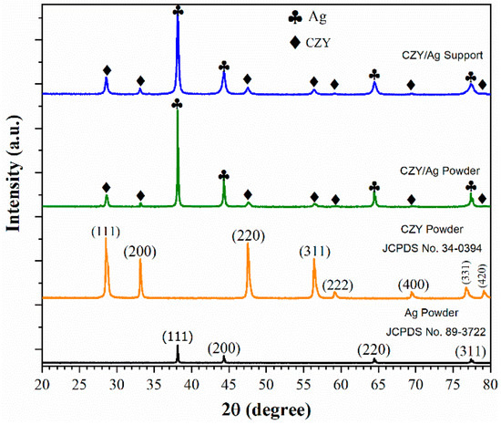
Figure 5.
XRD diffraction patterns of silver powder, CZY powder, cermet powder, and membrane support sintered at 900 °C for 20h.
3.2. CO2 and O2 Permeation Tests at High Temperatures
The results of the CO2 and O2 permeation studies at high temperatures are shown in Figure 6. As expected, the permeation flux increases as a function of temperature; this behavior has been commonly observed in this kind of membrane since transporting both species, CO2 and O2, is a phenomenologically concurrent process according to Reaction (1). Despite this, the percolation threshold of silver in the cermet support was not systematically determined; instead, the 30/70 vol.% CZY/Ag cermet was chosen to warrant the metallic behavior of the cermet and, therefore, the electronic conductivity of the membrane. Then, it can be argued that the membrane’s electronic conductivity property is not the process’s limiting factor. Although the electronic conductivity in the cermet must decrease with temperature, it has been reported that the total conductivity remains about three orders of magnitude higher than the carbonate ionic conductivity in the membrane [16]; therefore, those above should be a limiting factor in the membrane. For this reason, as the carbonate ion (CO32−) conduction increases in the carbonate by the temperature’s effect, CO2 and O2 permeation also increases.
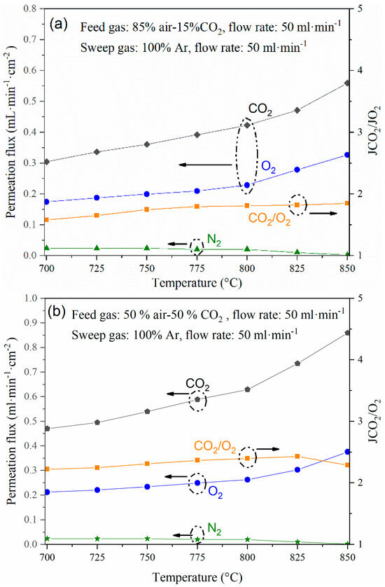
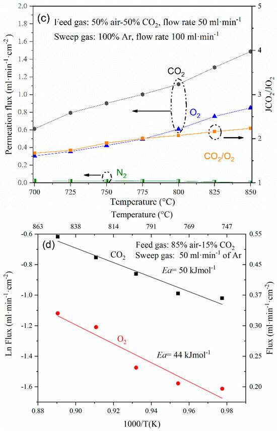
Figure 6.
(a–c) CO2 and O2 permeation flux through the dense cermet membrane using different feed gas mixtures and (d) Arrhenius plot of the experiment performed with a feed of 85 vol.% air-15 vol.% CO2 and sweep of 50 mL·min−1 of Ar, showing its activation energy (Ea).
The best parameter for elucidating the presence of defects in the membrane or the sealing, including microcracks or holes, is monitoring the N2 leak during the whole permeation test (Figure 6a–c). The setup and membrane were gas-tight, with a leak that never increased during the permeation tests. On the other hand, when studying the cermet-carbonate operation under different gas feed conditions, permeation flux increased between 700 °C and 850 °C. For example, with a feed gas composition of 15 vol.% of CO2 (Figure 6a), the CO2 permeation flux increases from 0.30 to 0.56 mL·min·cm2 at 700 and 850 °C, respectively, and changing the feed gas CO2 concentration to 50 vol.% (Figure 6b), permeation values of 0.47 to 0.86 mL·min·cm2 were observed at 700 and 850 °C, respectively. On the other hand, the permeation flux also increased by increasing the Ar sweep gas flow rate to 100 mL/min, showing values of 0.61 and 1.48 mL·min·cm2 at 700 and 850 °C, respectively (Figure 6c). In general, it was observed that the JCO2/JO2 ratio is maintained in the range of 1.9–2.4 for the different operating conditions; this is because the oxygen concentration in the permeate side is mainly related to CO32− transport (Reaction (1)). However, strictly speaking, for those JCO2/JO2 values above 2, an extra conducting path must be present for oxygen species, i.e., an interfacial transport mechanism, as has been previously observed in the cases of ceria-carbonate and LiAlO2-carbonate composites that exhibited oxygen ion conduction [24,25]. The Arrhenius activation energy values, Ea, for a feed gas of 85% air and 15% CO2 and a sweep Ar flow rate of 50 mL·min−1, which are shown in Figure 6d, corroborate this statement, with values of 44 kJ/mol for the O2 transport process and 50 kJ/mol for the CO2 transport process.
Regarding the selectivity, the highest values were observed at high temperatures; for example, for the gas feed containing 50% CO2 and Ar sweep of 100 mL·min−1, the membrane exhibited a selectivity of CO2/N2 = 718 and O2/N2 = 410 at 850 °C.
3.3. H2 Production in the OCRM Membrane Reactor
During the operation of the membrane reactor, the simultaneous and effective separation of CO2 and O2 was accomplished, followed by the catalytic conversion of CH4, CO2, and O2 into synthesis gas. Figure 7 shows the results of the membrane reactor test carried out at different temperatures between 700 and 850 °C. It was observed that both CO2 and CH4 conversion increase with temperature, reaching about 96 and 99% at 850 °C, respectively. Similar behavior was observed for the case of H2 and CO products; they reached a production rate of 3.2 and 1.7 mL·min−1·cm−2. The H2/CO ratio varied between 2.1–2.8. It is noteworthy that methane conversion is high in the temperature range where CO2 conversion does not exceed 70% (700–800 °C); also, this fact is attributed to the methane cracking reaction, which is thermodynamically feasible, and, for example, at 800°, cracking occurs according to the following reaction (Equation (4)):
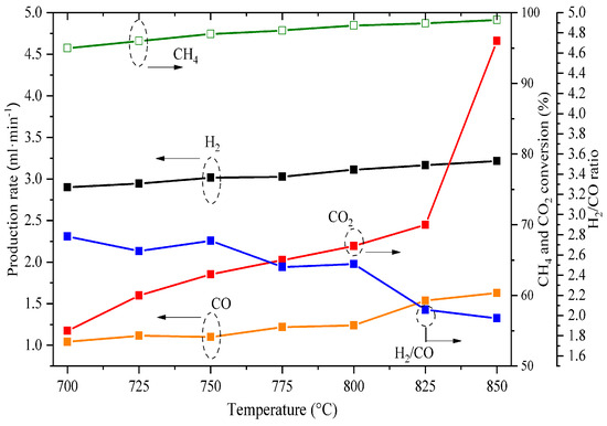
Figure 7.
Effect of temperature on the syngas production (H2 + CO), methane conversion, and H2/CO molar ratio under the studied oxy-CO2 reforming of methane conditions.
Stability is an essential parameter for the eventual applicability of membrane reactors. Figure 8 summarizes the performance of the membrane; first, a short-term stability test was carried out to corroborate the sealing state (checking for leaks) and then the initial permeation behavior. After the above, the effect of temperature on the permeation between 700 and 850 °C was evaluated. This procedure was then replicated for the operating conditions described in Figure 6. Finally, the OCRM process was performed over 15 h. The membrane reactor remained stable during the total operating period of about 115 h, and all the performed experiments were able to be carried out in the same membrane; therefore, at least at a laboratory scale, the membrane can be considered stable.
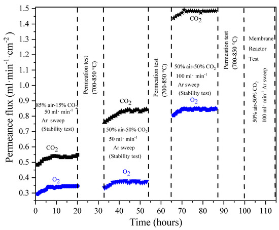
Figure 8.
The stability performance of CO2 and O2 permeation at different operating conditions was studied for the dense cermet-carbonate membranes, completing a total and continuous operating time of 115 h.
Once the OCRM study was completed, the used membrane was analyzed by XRD to determine its thermal and chemical stability (Figure 9). XRD patterns did not show the formation of new crystalline phases but only certain changes on the pattern profile, specifically for the Ag phase peaks, which increase in intensity and must be related to the crystal growth due to high temperatures and long times.
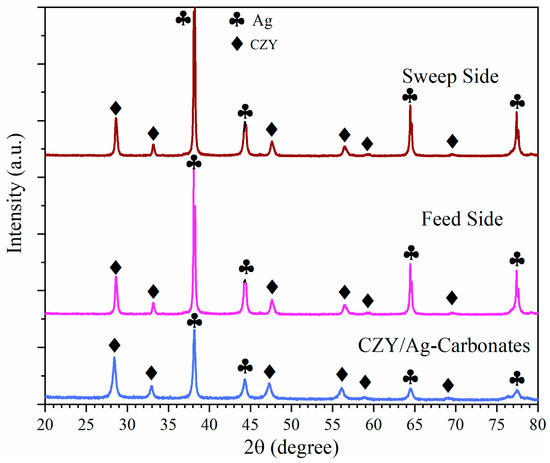
Figure 9.
XRD pattern of the dense ceramic–-carbonate membrane before testing and after continuous operation for 115 h from both the feed and sweep sides.
SEM was used to evaluate the effect of the prolonged exposure time at high temperatures on the membrane microstructure (Figure 10). Certain changes concerning the initial morphology were observed, especially in the presence of roughness, some porosity (Figure 10a), and the presence of big Ag particles that presumably experienced coarsening due to the incipient sintering of the support (Figure 10b); nevertheless, it is essential to emphasize that there was no significant N2 leakage during the permeation, stability, and reaction tests, which indirectly indicates membrane integrity, or in other words, that the membrane remains dense with no carbonate loss that could affect the membrane performance. Finally, as the literature reports that Ag partially dissolves into molten carbonate mixtures, EDS (punctual method) was performed on the carbonate-rich zone of the used membrane, showing no presence of Ag.
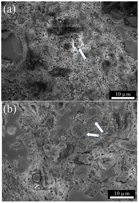
Figure 10.
SEM images of the membrane surface after 115 h of continuous operation: (a) surface exposed to the feed gas mixture and (b) surface exposed to the permeate; withe arrows show the coarsening of Ag phase.
4. Conclusions
TCZY/Ag cermet was made using the milling process to fabricate a carbonate-based membrane. The permeation test was successfully conducted at high temperatures of 700–850 °C under different feed and sweep conditions to elucidate the effect of CO2 concentration in the feed and Ar flow rate in the sweep on the simultaneous separation of CO2 and O2. The evaluated membrane exhibits high permeation flux of 1.48 and 0.84 mL·min−1·cm−2 by operating with a feed gas mixture of 50 vol.% air, 50 vol.% CO2, and 100 mL·min−1·cm−2 of Ar as the sweep gas at 850 °C. Subsequently, the use of the 10 wt.% Ni/CeO2 packed catalyst and the fabricated CZY/Ag and carbonate membrane allow an efficient membrane reactor assembly to perform the OCRM reaction to obtain syngas and, therefore, produce H2. The membrane reactor exhibited excellent thermal and chemical stability because of the use of the CZY filler in the Ag-based cermet. It can be argued that the Ag matrix provides metallic properties to the cermet, and the ceramic filler enhances the wettability against carbonates and avoids the sintering and poisoning of the membrane surface by carbon deposition. The CH4 conversion, CO2 conversion, and H2 production reach values of 99%, 96%, and 3.2 mL·min−1·cm−2, respectively, by operating the reactor at 850 °C. The reactor performance remained stable, reaching a total and continuous operating time of 115 h. This work shows the advantageous use of Ag-based cermet materials as support for the preparation of carbonate-based membranes. Moreover, the conscientious selection of the ceramic filler enhances the fabrication of membrane reactors, showing excellent performance and long-term operation stability.
Supplementary Materials
The following supporting information can be downloaded at: https://www.mdpi.com/article/10.3390/chemengineering8050106/s1. Figure S1: Synthesis approach description and XRD characterization of the obtained CZY samples. A complete solid solution was obtained after the third cycle of grinding and calcination; Figure S2: OM image of the membrane thickness and cross-section; Figure S3: The membrane reactor schematization.
Author Contributions
Conceptualization, J.O.-L.; Methodology, J.A.R.-C. and J.O.-L.; Formal analysis, J.O.-L.; Investigation, J.A.R.-C. and J.A.F.-A.; Data curation, J.A.R.-C.; Writing—original draft, J.A.R.-C. and J.O.-L.; Writing—review and editing, J.A.R.-S., C.C.-F., H.B.-R. and O.O.-E.; Funding acquisition, J.O.-L. All authors have read and agreed to the published version of the manuscript.
Funding
This research was supported by SIP-IPN, Project No. 20240215, and CONAHCYT, “Ciencia Básica y de Frontera 2023–2024”, Project No. CBF2023-2024-1992.
Data Availability Statement
Data is contained within the article or Supplementary Materials.
Acknowledgments
The authors express their appreciation to the SIBE-IPN, EDI-IPN, and BEIFI-IPN programs for financial support.
Conflicts of Interest
The authors declare no conflicts of interest.
References
- Madejski, P.; Chmiel, K.; Subramanian, N.; Kuś, T. Methods and Techniques for CO2 Capture: Review of Potential Solutions and Applications in Modern Energy Technologies. Energies 2022, 15, 887. [Google Scholar] [CrossRef]
- Shukla, S.K.; Khokarale, S.G.; Bui, T.Q.; Mikkola, J.T. Ionic Liquids: Potential Materials for Carbon Dioxide Capture and Utilization. Front. Mater. 2019, 6, 42. [Google Scholar] [CrossRef]
- Isaifan, R.J.; Amhamed, A. Review on Carbon Dioxide Absorption by Choline Chloride/Urea Deep Eutectic Solvents. Adv. Chem. 2018, 2018, 1–6. [Google Scholar] [CrossRef]
- Mazari, S.A.; Ali, B.S.; Jan, B.M.; Saeed, I.M.; Nizamuddin, S. An overview of solvent management and emissions of amine-based CO2 capture technology. Int. J. Greenh. Gas Control 2015, 34, 129–140. [Google Scholar] [CrossRef]
- Anantharaman, R.; Peters, T.; Xing, W.; Fontaine, M.L.; Bredesen, R. Dual phase high-temperature membranes for CO2 separation performance assessment in post- and pre-combustion processes. Faraday Discuss. 2016, 192, 251–269. [Google Scholar] [CrossRef]
- Zhang, P.; Tong, J.; Huang, K. Dry-Oxy Methane Reforming with Mixed e–/CO32– Conducting Membranes. ACS Sustain. Chem. Eng. 2017, 5, 5432–5439. [Google Scholar] [CrossRef]
- Ovalle-Encinia, O.; Pfeiffer, H.; Ortiz-Landeros, J. Ce0.85Sm0.15O2-Sm0.6Sr0.4Al0.3Fe0.7O3 composite for the preparation of dense ceramic-carbonate membranes for CO2 separation. J. Membr. Sci. 2018, 547, 11–18. [Google Scholar] [CrossRef]
- Ortega-Lugo, R.; Fabian-Anguiano, J.A.; Ovalle-Encinia, O.; Gómez-Yáñez, C.; Zeifert, B.H.; Ortiz-Landeros, J. Mixed-conducting ceramic-carbonate membranes exhibiting high CO2/O2 permeation flux and stability at high temperatures. J. Adv. Ceram. 2020, 106, 94–106. [Google Scholar] [CrossRef]
- Chung, S.J.; Park, J.H.; Li, D.; Ida, J.I.; Kumakiri, I.; Lin, J.Y.S. Dual-Phase Metal-Carbonate Membrane for High-Temperature Carbon Dioxide Separation. Ind. Eng. Chem. Res. 2005, 44, 7999–8006. [Google Scholar] [CrossRef]
- Xu, N.; Li, X.; Franks, M.A.; Zhao, H.; Huang, K. Silver-molten carbonate composite as a new high-flux membrane for electrochemical separation of CO2 from flue gas. J. Membr. Sci. 2012, 401–402, 190–194. [Google Scholar] [CrossRef]
- Zhang, L.; Gong, Y.; Yaggie, J.; Wang, S.; Romito, K.; Huang, K. Surface modified silver-carbonate mixed conducting membranes for high flux CO2 separation with enhanced stability. J. Membr. Sci. 2014, 453, 36–41. [Google Scholar] [CrossRef]
- Fang, J.; Tong, J.; Huang, K. A superior mixed electron and carbonate-ion conducting metal-carbonate composite membrane for advanced flue-gas carbon capture. J. Membr. Sci. 2016, 505, 225–230. [Google Scholar] [CrossRef]
- Tong, J.; Si, F.; Zhang, L.; Fang, J.; Han, M.; Huang, K. Stabilizing electrochemical carbon capture membrane with Al2O3 thin-film overcoating synthesized by chemical vapor deposition. Chem. Commun. 2015, 51, 2936–2938. [Google Scholar] [CrossRef]
- McNeil, L.A.; Mutch, G.A.; Lacoviello, F.; Bailey, J.J.; Triantafyllou, G.; Neagu, D.; Miller, T.S.; Papaioannou, E.I.; Hu, W.; Brett, D.J.L.; et al. Dendritic silver self-assembly in molten-carbonate membranes for efficient carbon dioxide capture. Energy Environ. Sci. 2020, 13, 1766–1775. [Google Scholar] [CrossRef]
- Zhang, P.; Tong, J.; Jee, Y.; Huang, K. Stabilizing a high-temperature electrochemical silver-carbonate CO2 capture membrane by atomic layer deposition of a ZrO2 overcoat. Chem. Commun. 2016, 52, 9817–9820. [Google Scholar] [CrossRef]
- Fabián-Anguiano, J.A.; Ramírez-Moreno, M.J.; Balmori-Ramírez, H.; Romero- Serrano, J.A.; Romero-Ibarra, I.C.; Ma, X.; Ortiz-Landeros, J. Syngas production with CO2 utilization through the oxidative reforming of methane in a new cermet-carbonate packed-bed membrane reactor. J. Membr. Sci. 2021, 637, 119607. [Google Scholar] [CrossRef]
- Mendoza-Serrato, C.G.; López-Juárez, R.; Reyes-Montero, A.; Romero-Serrano, J.A.; Gómez-Yáñez, C.; Fabián-Anguiano, J.A.; Ortiz-Landeros, J. Performance of membranes based on novel Ce0.8Sm0.2O2-δ /Ag cermet and molten carbonates for CO2 and O2 separation. Chem. Eng. Sci. 2022, 255, 117673. [Google Scholar] [CrossRef]
- Zhang, P.; Tong, J.; Huang, K. Self-Formed, Mixed-Conducting, Triple-Phase Membrane for Efficient CO2/O2 Capture from Flue Gas and in Situ Dry-Oxy Methane Reforming. ACS Sustain. Chem. Eng. 2018, 6, 14162–14169. [Google Scholar] [CrossRef]
- Fabián-Anguiano, J.A.; Mendoza-Serrato, C.G.; Gómez-Yáñez, C.; Zeifert, B.H.; Ma, X.; Ortiz-Landeros, J. Simultaneous CO2 and O2 separation coupled to oxy-dry reforming of CH4 by means of a ceramic-carbonate membrane reactor for in situ syngas production. Chem. Eng. Sci. 2019, 210, 115250. [Google Scholar] [CrossRef]
- Shafer, W.D.; Gnanamani, M.K.; Graham, U.M.; Yang, J.; Masuku, C.M.; Jacobs, G.; Davis, B.H. Fischer-Tropsch: Product Selectivity-The Fingerprint of Synthetic Fuels. Catalysts 2019, 9, 259. [Google Scholar] [CrossRef]
- Wentrup, J.; Pesch, G.R.; Thöming, J. Dynamic operation of Fischer-Tropsch reactors for power-to-liquid concepts: A review. Renew. Sustain. Energy Rev. 2022, 162, 112454. [Google Scholar] [CrossRef]
- Anchieta, C.G.; Assaf, E.M.; Assaf, J.M. Syngas production by methane tri-reforming: Effect of Ni/CeO2 synthesis method on oxygen vacancies and coke formation. J. CO2 Util. 2022, 56, 101853. [Google Scholar] [CrossRef]
- ASTM C830-00; Standard Test Methods for Apparent Porosity, Liquid Absorption, Apparent Specific Gravity, and Bulk Density of Refractory Shapes by Vacuum Pressure. ASTM International: West Conshohocken, PA, USA, 2023.
- Amar, I.A.; Lan, R.; Petit, C.T.G.; Tao, S. Electrochemical Synthesis of Ammonia Based on Co3Mo3N Catalyst and LiAlO2-(Li,Na,K)2CO3 Composite Electrolyte. Electrocatalysis 2015, 6, 286–294. [Google Scholar] [CrossRef]
- Zhu, B.; Li, S.; Mellander, B.E. Theoretical approach on ceria-based two-phase electrolytes for low temperature (300–600 °C) solid oxide fuel cells. Electrochem. Commun. 2008, 10, 302–305. [Google Scholar] [CrossRef]
Disclaimer/Publisher’s Note: The statements, opinions and data contained in all publications are solely those of the individual author(s) and contributor(s) and not of MDPI and/or the editor(s). MDPI and/or the editor(s) disclaim responsibility for any injury to people or property resulting from any ideas, methods, instructions or products referred to in the content. |
© 2024 by the authors. Licensee MDPI, Basel, Switzerland. This article is an open access article distributed under the terms and conditions of the Creative Commons Attribution (CC BY) license (https://creativecommons.org/licenses/by/4.0/).