Article

Numerical Study of CO2 Removal from Inhalational Anesthesia System by Using Gas-Ionic Liquid Membrane

Independent Research Scientist, Petach-Tiqwa 4942136, Israel
ChemEngineering 2023, 7(4), 60; https://doi.org/10.3390/chemengineering7040060
Submission received: 9 April 2023 / Revised: 21 June 2023 / Accepted: 10 July 2023 / Published: 12 July 2023

Abstract

:
Inhalational anesthesia is supplied through an assisted ventilation system. It is mostly composed of xenon or nitrous oxide, halogenated hydrocarbons (HHCs), and oxygen. In order to reduce costs of the anesthesia compounds, the remaining anesthetics present in exhalation are recycled and reused, in order to minimize the amount of fresh anesthesia. An alkali hydroxide mixture (called soda lime) is employed in order to remove CO2 from the exhalation. However toxic compounds may be formed during the reaction of soda lime with halogenated hydrocarbons. Ionic liquids (ILs) have several advantages such as non-volatility, functionality, high carbon solubility, and low energy requirements for regeneration. In the framework of this research, carbon dioxide removal with ionic liquids has been numerically studied. COMSOL multi-physics finite element software has been applied. It solves the continuity, fluid flow, and diffusion equations. A new algorithm has been developed for calculating the infrared (IR) radiation absorption of CO2. Its absorption coefficient has wavelength-dependent properties. The gaseous absorption coefficient has been calculated by using HITRAN spectral database. It has been found that the CO2 is absorbed almost completely by the 1-ethyl-3-methylimidazolium dicyanamide ([emim][DCA]) ionic liquid after a period of 1000 s. It has been shown that the absorption coefficient of CO2 can be neglected in the interval below 1.565 μm, and then at 1.6 μm, it increases to the same order as that for CO. Thus, it is possible to detect CO2 by applying a laser diode which is capable to transmit IR radiation at a wavelength of 1.6 μm. This time period is a function of the diffusion coefficient of the CO2 in the membrane and in the ionic liquid.

1. Introduction

1.1. Separation Methods

Components separation of mixtures may be divided into two classes. One class is called the diffusional operation. It involves phase changes or transfer of material from one phase to another. The second class is called mechanical separations. They are useful in separating solid particles or liquid drops [1]. The most common method used in artificial lungs to remove CO2 is called extracorporeal membrane oxygenation (ECMO). ECMO involves pumping the patient’s blood through an artificial lung, where the CO2 is removed and replaced with oxygen. The oxygenated blood is then returned to the patient’s body. Another method used in artificial lungs for CO2 removal is called extracorporeal carbon dioxide removal (ECCO2R). ECCO2R uses a machine to remove CO2 from the blood through a process called adsorption. In this process, the blood is circulated through a filter containing a material that binds to and removes CO2 from the blood. The CO2-free blood is then returned to the patient’s body [2,3,4].

1.2. Review of the Carbon Dioxide Removal by Applying Ionic Liquids

Ionic liquids (ILs) are composed of cations and anions at relatively low temperatures and low vapor pressures. They have chemical and thermal stability and low flammability [5]. They have been applied in organic reactions as solvents, catalysts, and thermal storage fluids [6,7]. Their higher cost may be reduced. This is because they can be easily recycled [8]. They can be extracted with solvents, and separated by applying membranes [9,10]. The application of ionic liquids in carbon separations is considered one of the promising methods to mitigate carbon emissions. Amine-based solvents have been mostly used so far, because of their large cyclic capacities. However, the use of these solvents is threatened by their degradation at high temperatures and high corrosion rate (which may cause amine stress corrosion cracking to the steel pipes) [11,12].

1.2.1. Numerical Simulations of Carbon Separations by Applying Ionic Liquids

Sohaib et al. [13,14] have carried out a coupled simulation of ionic liquids (ILs) with a membrane contactor for post-combustion CO2 capture at moderate temperatures and pressures. In the framework of their research, four types of ionic liquids have been selected due to their high carbon solubility and thermal stability. These ionic liquids were able to capture a substantial amount of carbon dioxide during the specified operating time. Xie [15] has studied CO2 separation with conventional imidazolium-based ionic liquids and novel ionic liquids. The novel ionic liquid choline chloride/urea has been chosen as the solvent to separate carbon because of its lower price and environmental qualities [15]. It has been found that the addition of water to novel ionic liquid has a minor effect on the density and CO2 solubility [15]. Altintas and Keskin [16] have performed Monte Carlo simulations on 1661 metal–organic frameworks (MOFs) to compute CO2/N2 gaseous mixture adsorption data and then calculated selectivity.

1.2.2. Review of CO2 Removal Membranes

Membrane technology is applied in a large number of separation processes. The benefits of membrane technology are as follows: the separation can be carried out continuously; energy consumption is generally low; and membrane separation processes can be easily combined with other separation methods [17]. Ghasem has studied the chemical removal process of carbon dioxide from a CO2/N2 gas mixture in an aqueous methyldiethanolamine (MDEA)-based carbon nanotube (CNT) in a hollow fiber membrane (HFM) contactor [18]. A CO2 removal membrane is a type of technology designed to selectively remove carbon dioxide (CO2) from gas mixtures, such as those found in industrial processes or power generation facilities. The membrane works by using a selective polymer material that allows CO2 to pass through while blocking other gases such as nitrogen or oxygen [19,20,21]. CO2 removal membranes are typically used in applications where the separation of CO2 from gas mixtures is necessary, such as in carbon capture and storage (CCS) systems or natural gas processing. These membranes are considered to be an attractive option for CO2 separation due to their relatively low cost, energy efficiency, and ease of operation compared to other separation technologies such as amine scrubbing or cryogenic distillation. Al-Marzouqi et al. have studied the removal of CO2 from a mixture of gas streams by using several solvents and different commercial membrane contactors [19]. It has been found that CO2 removal decreased with increasing temperature for physical absorption [19]. Thakkar et al. have applied fabricated (3D)-printed zeolite monoliths with novel structures in order to remove CO2 from the air [20]. Michenkova et al. have observed that some membranes are CO2 impermeable [21]. Chuah et al. [22] reviewed the state-of-the-art studies which deal with CO2 absorption using membrane contactors. This research focused on membrane materials, liquid absorbents, process design, and pilot-scale demonstration of membrane contactor processes. Martins has proposed an alternative process to remove carbon dioxide through the use of a membrane contactor combined with a biocompatible ionic liquid (IL), choliniumlysinate, with high absorption capacity [23,24].

1.2.3. HITRAN Spectral Database

HITRAN (high-resolution transmission molecular absorption database) is a comprehensive spectroscopic database of molecular transitions that arise from the interactions of molecules with electromagnetic radiation. The database includes information on the energy levels, line positions, line strengths, and other spectroscopic parameters of a wide range of molecular species. HITRAN is widely used in atmospheric and environmental research, as well as in astrophysics and other fields that involve the study of molecular interactions with radiation. The database is updated regularly to include new molecular species and to improve the accuracy and completeness of the data. HITRAN is available online and can be accessed at https://www.cfa.harvard.edu/hitran/ (accessed on 9 July 2023). The database can be searched and downloaded in various formats, and it also provides tools for simulating and analyzing the spectral signatures of different molecules under different conditions [25,26,27]. Figure 1 illustrates the file structure of the HITRAN database [26].

1.2.4. Scope and Novelty of This Paper

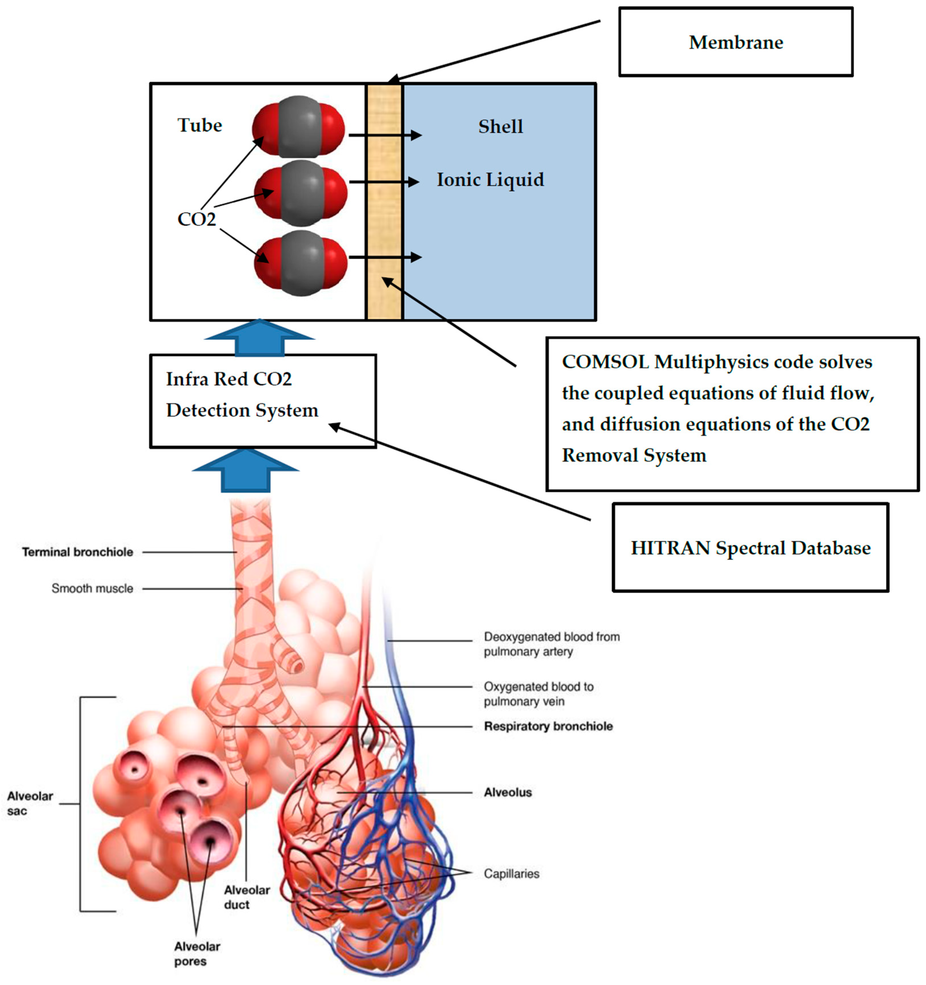
Although there have been some studies exploring the potential use of ionic liquids in anesthesia, the research is still in its early stages. The focus is primarily on developing new local anesthetics using ionic liquids as carriers or additives. These studies aim to improve the solubility and stability of conventional local anesthetics or explore new mechanisms of action. In the framework of this research, carbon dioxide separation with conventional imidazolium-based ionic liquids has been numerically studied. This paper includes the simulation of the carbon dioxide capture system. COMSOL multi-physics code has been employed and simultaneously solves the continuity, fluid flow, and diffusion equations. In the framework of this research a new algorithm has been developed for calculating the infrared (IR) radiation absorption of CO2. Its absorption coefficient has wavelength-dependent properties. The gaseous absorption coefficient has been calculated by using HITRAN spectral database. As far as I know, this work is the first coupled CFD simulation of a CO2 removal system and CO2 detection system based on the HITRAN spectral database. This system is shown in Figure 2.

2. Materials and Methods

2.1. Diffusion Coefficients of Ionic Liquid

1-ethyl-3-methylimidazolium dicyanamide ([emim][DCA]) ionic liquid has been selected due to its high thermal stability, moderate viscosity, and surface tension, as well as its high CO2 diffusion coefficient. The diffusion coefficients of the CO2 inside the gaseous mixture, [emim][DCA] ionic liquid, and the membrane are shown in Table 1 [13,28,29,30].

2.2. Multiphysics Analyses of the Carbon Removal Device

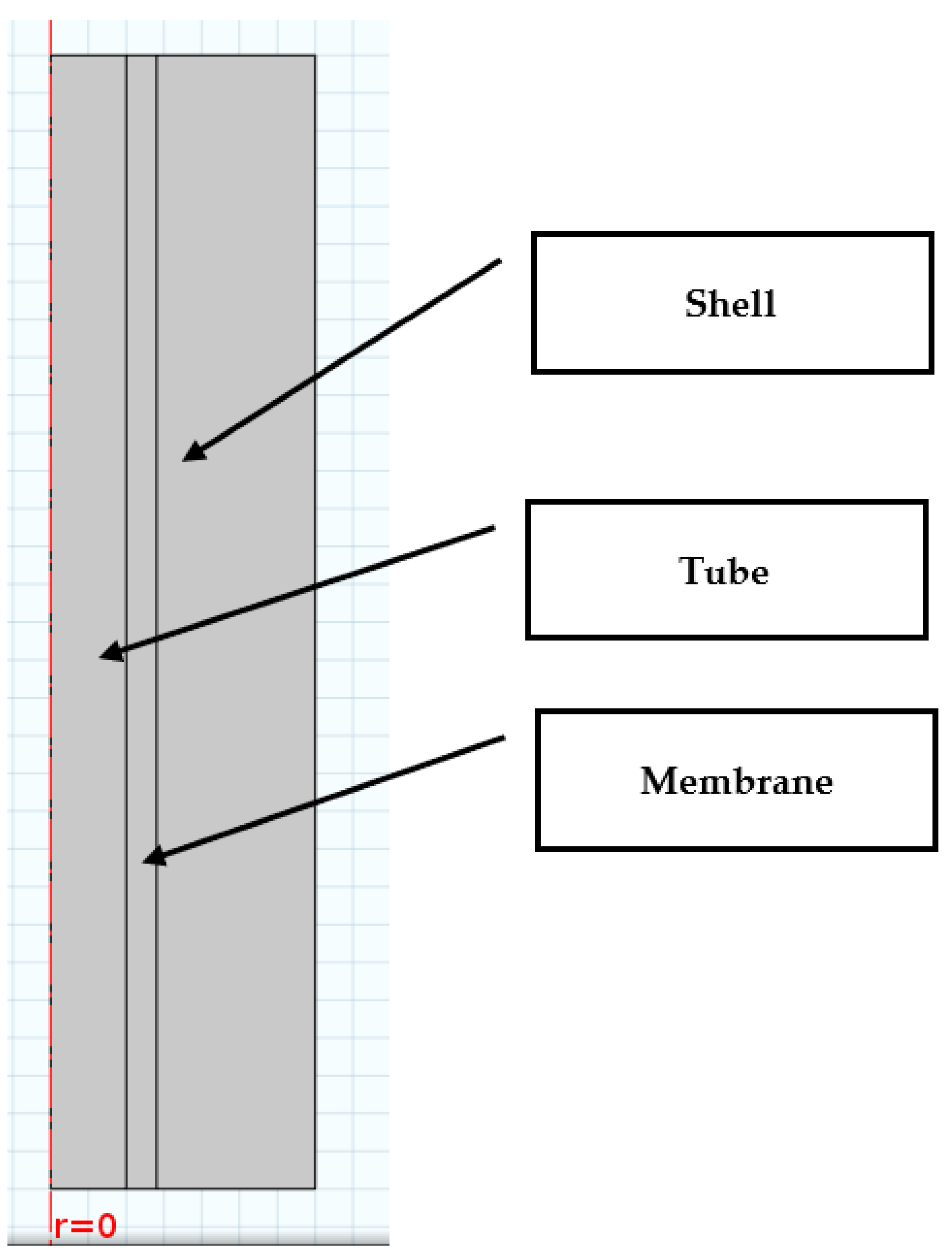
This part deals with the numerical analysis of the carbon removal device. Figure 3 shows the geometry of this system.
The carbon removal system is composed of a tube, membrane, and shell. The tube thickness is 0.2 mm, and its length is 40 mm. The membrane thickness is 0.28 mm. The shell thickness is 0.42 mm. COMSOL multi-physics finite element software has been applied in this work. It solved fluid flow, continuity, and diffusion transport equations.

2.2.1. Fluid Flow and Continuity Equations

Since the flow inside the tube is very slow and incompressible, it is assumed that the flow is laminar. The flow of species is described by applying the transient Navier–Stokes transport equation [31]:
ρ u / t η ( u + ( u ) T ) + ρ u u + p = 0
The mass conservation transport equation for the reacting species is [31]:
u = 0

2.2.2. Diffusion Equations inside the CO2 Removal System

The mass transfer in the separations reactor contains convection and diffusion terms. The transient diffusion equation for the tube section is provided in Equation (3) [31]:
c 1 / t + ( D c o 2 g a s c 1 + c 1 u ) = 0
The time-dependent diffusion equation for the membrane is provided in Equation (4) [31]:
c 2 / t + ( D m c 2 ) = 0
The transient diffusion equation (it is assumed that the velocity of the ionic liquid may be neglected) for the ionic liquid section is provided in Equation (5) [31]:
c 3 / t + ( D c o 2 I L c 3 ) = 0

2.2.3. Boundary Conditions

The boundary conditions at the interface of the mixture section and the membrane is shown in Equation (6) [30]:
( D c o 2 g a s c 1 + c 1 u ) n = D m c 2
It is assumed that the CO2 concentration entering the removal system is 1000 mol/m3. The velocity of the gaseous mixture is 0.1 m/s. The boundary conditions at the interface of the membrane and the capture section are shown in Equations (7)–(9) [31]:
( D c o 2 I L c 3 ) n = D m c 2
c 1 ( 0 < r < r i n , z = 0 , t ) = c i n
u ( 0 < r < r i n , z = 0 , t ) = v i n

2.3. IR Radiative Properties of CO2—LBL Model

The LBL calculation is based on HITRAN spectral database, Rothman et al. [32] (see Figure 1). IR absorption by CO2 has been calculated here by applying line-by-line (LBL) method in the wavelength interval of 1.57–1.6 µm. It is considered the most accurate method and is used for solving the radiative transfer equation (RTE) for participating medium (absorbing and scattering) containing hot gases. It is applied as a reference model for validating narrow-band and wide-band models. It takes into account, at high resolution, the contributions of all the significant absorbing lines of the various species in the mixture, cf. Taine et al. [33]. A line i, centered at wave number ν i , is characterized by an intensity S i ( T S ) , at the standard temperature T S = 298   K , and a normalized profile F i ( ν ν i ) , of the Lorentz, Voigt, or Doppler type. The absorption coefficient for the component j, κ ν , i j , at wave number ν , associated with line i, is calculated by the following equation [34]:
κ ν , i j = n j S i ( T ) F i ( ν ν i )
The LBL method is a powerful method and accurate approach used in atmospheric and astrophysical remote sensing to calculate the radiative transfer of electromagnetic radiation through the Earth’s atmosphere or other media. The key steps involved in the line-by-line method are as follows:
(a).
Spectral Line Data: The method relies on a comprehensive spectroscopic database, such as HITRAN (high-resolution transmission molecular absorption) or other similar databases. These databases provide information about molecular absorption lines, including their positions, intensities, broadening parameters, and other relevant parameters.
(b).
Line Shape Function: To account for the Doppler, pressure, and temperature broadening effects (In this case the HITEMP is applied—see Figure 1), the spectral lines’ shapes are usually convoluted with appropriate line shape functions, such as the Voigt profile, which combines both Gaussian and Lorentzian line shapes.

3. Results

This section shows the numerical results for the infrared spectral absorption simulations and the concentration field inside the carbon dioxide removal device.

3.1. Calculation Results of the Infrared (IR) Radiation Absorption of CO and CO2

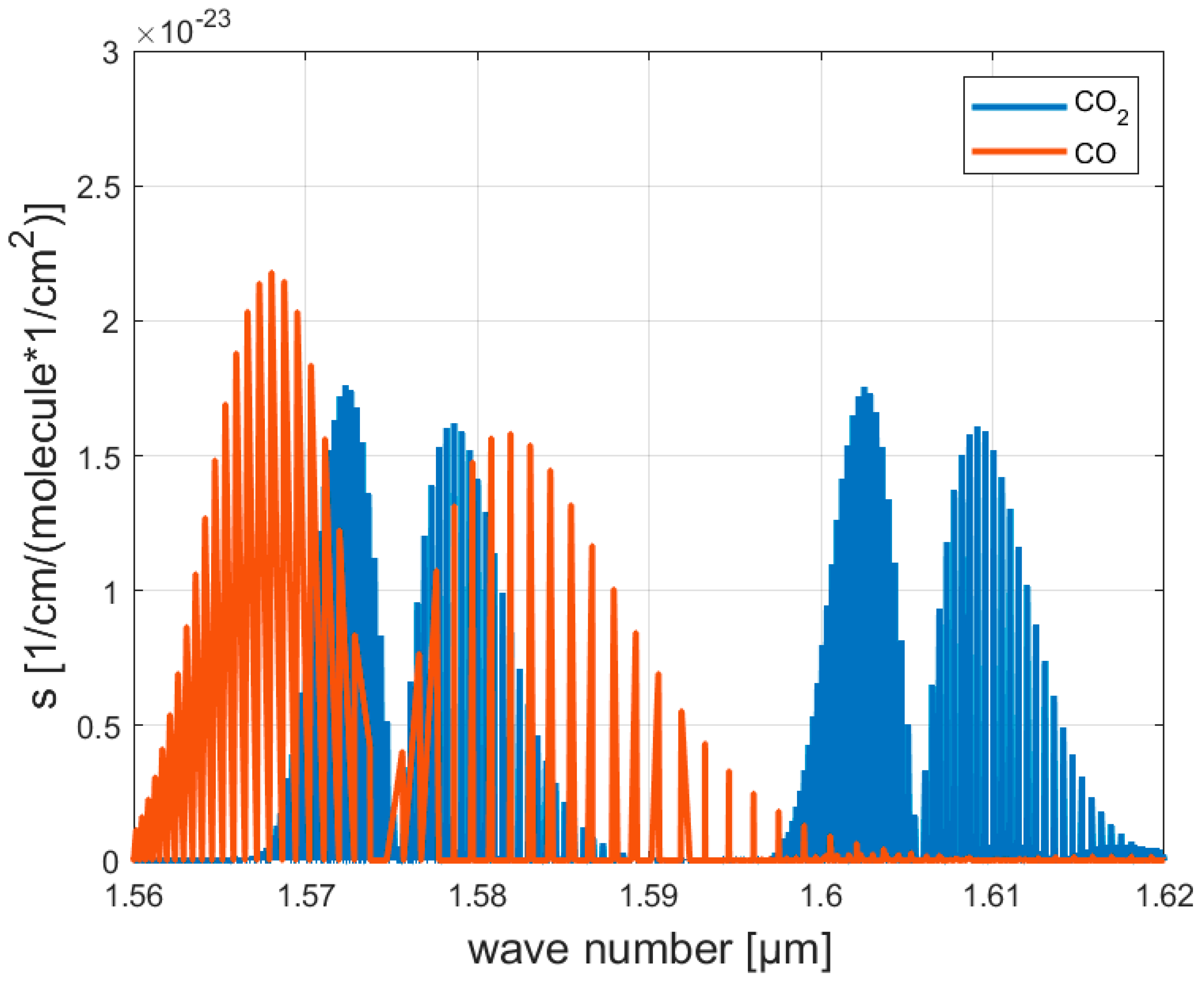
Figure 4 shows the calculated absorption spectra of pure CO2 and pure CO in the wavelength interval 1.56–1.62 µm. Figure 4 shows that the absorption coefficient of CO2 can be neglected in the interval below 1.565 μm, and then at 1.6 μm, it increases to the same order as that for CO. Thus, it is possible to detect CO2 by applying a laser diode which is capable of transmitting IR radiation at a wavelength of 1.6 μm.

3.2. Numerical Model Convergence

The numerical solution convergence graph is shown in Figure 5.
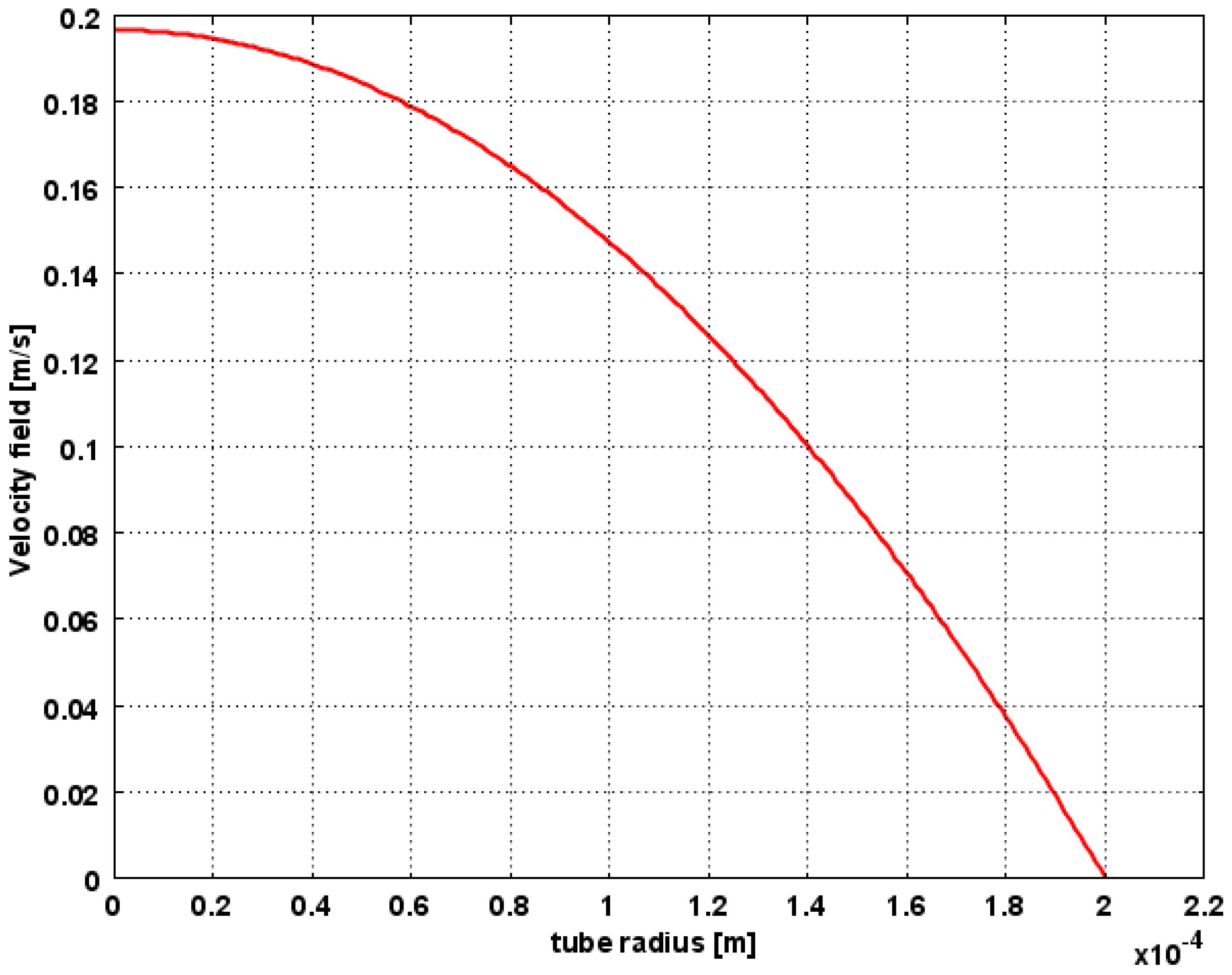
Figure 5 shows that the numerical errors have been decreased by 19 magnitudes (from 1 × 10⁹ to 1 × 10⁻¹³). Figure 6 shows the velocity profile of the gaseous mixture inside the tube.
Figure 5 shows that the gaseous mixture flows with a fully developed laminar parabolic velocity profile (Hagen–Poiseuille velocity profile). The gaseous mixture velocity is maximal at r = 0. Figure 7 shows the 2D plot of the carbon dioxide concentration profile at t = 100 s.
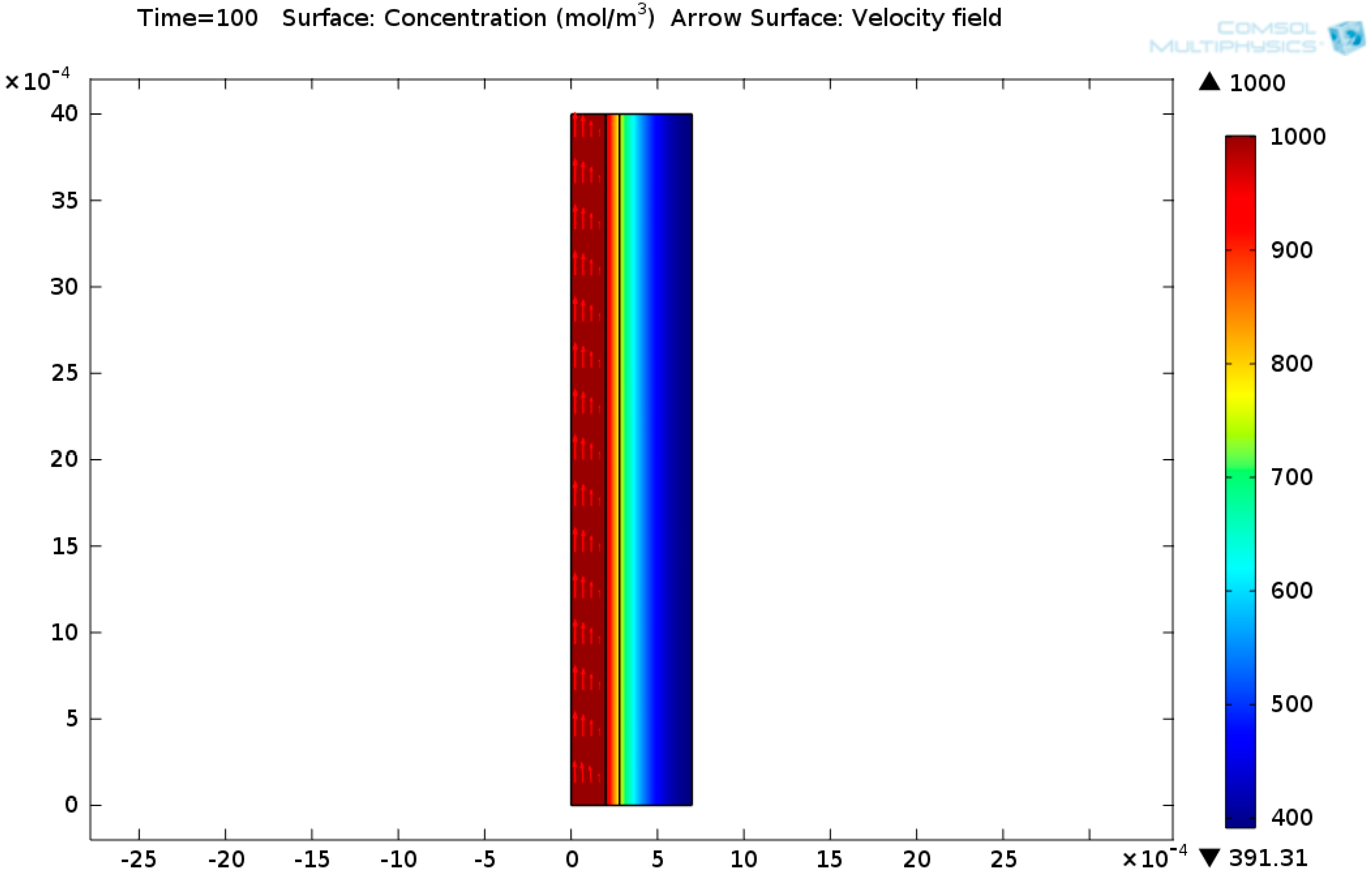
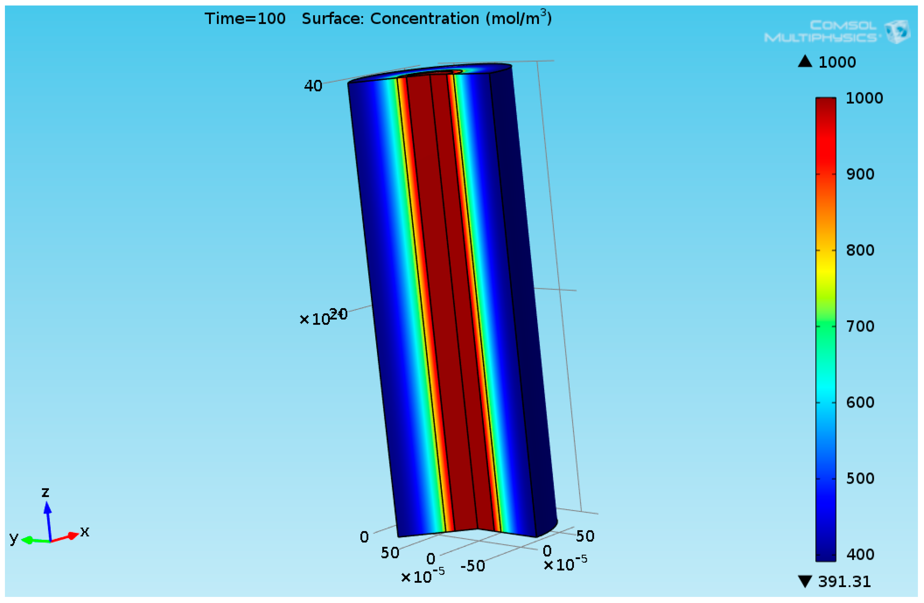
It can be seen from Figure 7 that the carbon dioxide concentration decays along the radius. This is because the carbon dioxide is absorbed in the membrane and the ionic liquid. Figure 8 shows 3D plot of the carbon dioxide concentration profile at t = 100 s.
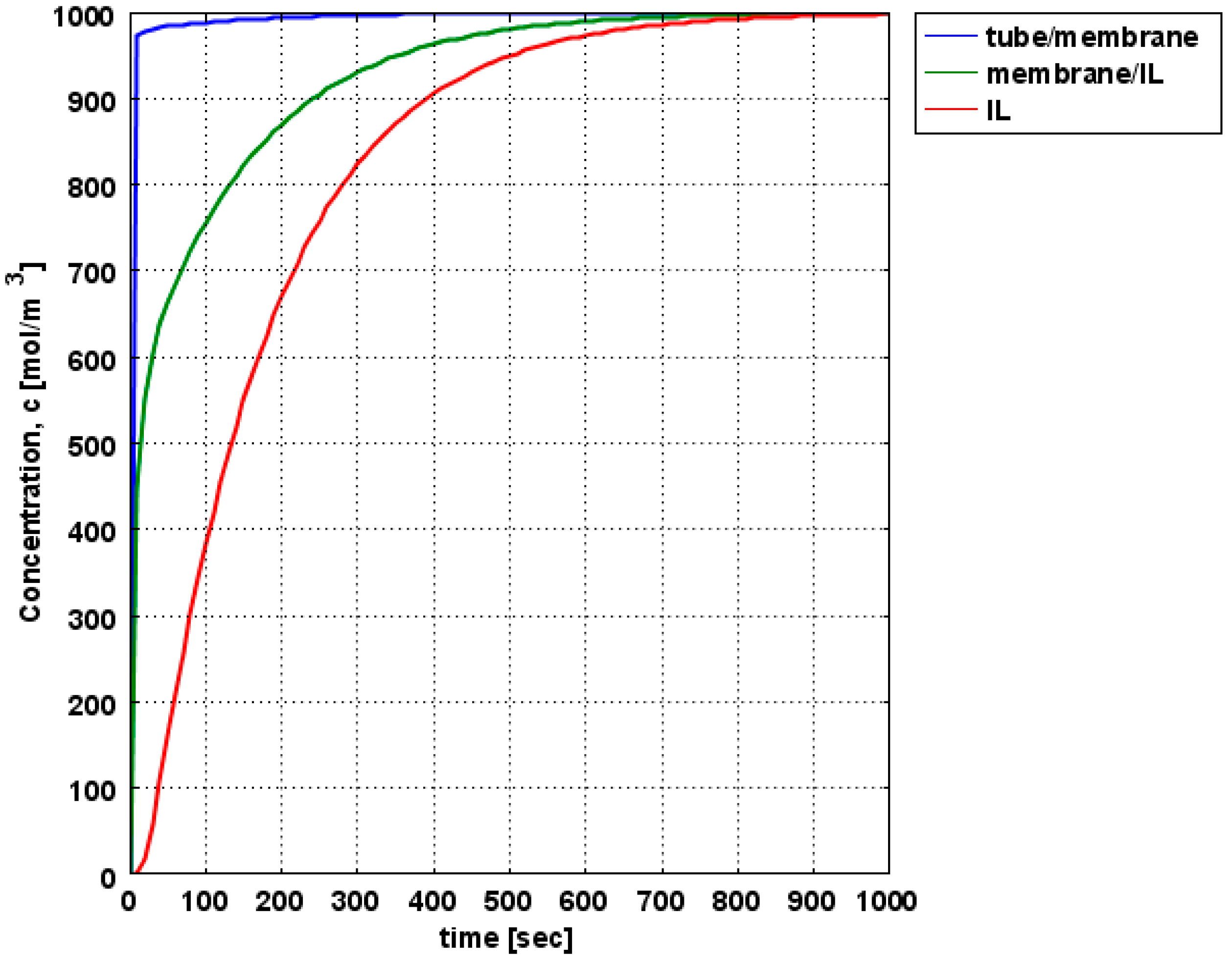
Figure 9 shows the calculated CO2 concentrations obtained at the different locations (tube/membrane interface, membrane/IL interface, and the edge of the ionic liquid section) of the removal system (1640 elements).
It can be seen from Figure 9 that the CO2 is absorbed almost completely by the 1-ethyl-3-methylimidazolium dicyanamide ([emim][DCA]) ionic liquid after 1000 s. This time period is a function of the diffusion coefficients of the CO2 in the membrane and in the ionic liquid. The CO2 concentrations profile is similar to the CO2 concentration profile shown in [24]. The numerical results obtained in this work have been compared to the paper written by Sohaib et al. [13]. The numerical results obtained in this work are similar to the results obtained in their paper.
The CO2 concentration at the tube membrane interface (blue curve) is enhanced because of the convective flow of the gaseous mixture inside the tube and the thin layer of the membrane. Mesh sensitivity analysis has been performed. Two CFD simulations with different meshes (1640 and 6560 elements) have been carried out by using COMSOL multiphysics finite element code. Figure 10 shows the calculated CO2 concentrations obtained at the different locations (tube/membrane interface, membrane/IL interface, and the edge of the ionic liquid section) of the removal system (6560 elements).
The CO2 concentrations obtained from these two CFD simulations are similar.

4. Conclusions and Future Work

Inhalational anesthesia is supplied through an assisted ventilation system. It is mostly composed of xenon or nitrous oxide, halogenated hydrocarbons (HHCs), and oxygen. In order to reduce costs of the anesthesia compounds, the remaining anesthetics present in exhalation are recycled and reused, in order to minimize the amount of fresh anesthesia. An alkali hydroxide mixture (called soda lime) is employed in order to remove CO2 from the exhalation. However, toxic compounds may be formed during the reaction of soda lime with halogenated hydrocarbons. Procedures for separating the components of mixtures fall into two classes. One class includes a method called diffusional operation, which involves phase changes or transfer of material from one phase to another. The second class includes methods, called mechanical separations, which are useful in separating solid particles or liquid drops. Ionic liquids (ILs) are composed of cations and anions at relatively low temperatures and low vapor pressures. Their advantages are chemical and thermal stability and low flammability. Thus, they have been applied in organic reactions as solvents, catalysts, and thermal storage fluids. Their higher cost may be reduced. This is because they can be easily recycled. They can be extracted with solvents, and separated by applying membranes. The application of ionic liquids in carbon separations is considered one of the promising methods to mitigate carbon emissions. Ionic liquids have several advantages for carbon capture applications compared to traditional solvents or absorption processes. Here are some of the key advantages:
(1)
High selectivity: Ionic liquids can exhibit high selectivity for CO2 capture, allowing for efficient separation from gas mixtures. Their unique chemical structures and tunable properties can be designed to enhance CO2 absorption while minimizing the absorption of other gases.
(2)
Low volatility: Ionic liquids are non-volatile, meaning they have negligible vapor pressure at ambient conditions. This characteristic eliminates the risk of emissions from solvent evaporation, making them safer and more environmentally friendly.
(3)
Wide temperature range: Ionic liquids can be tailored to remain in a liquid state over a broad temperature range, including near-ambient conditions. This flexibility enables their use in various carbon capture applications, including flue gas from power plants or industrial processes.
(4)
Chemical stability: Ionic liquids are typically chemically stable and can withstand harsh conditions, such as high temperatures and corrosive environments. This stability allows for long-term use without significant degradation or the need for frequent replacement.
(5)
Lower energy requirements: Ionic liquids can have low energy requirements for CO2 desorption, enabling more energy-efficient carbon capture processes. The energy demand for regeneration can be reduced compared to traditional solvents, resulting in lower operational costs.
(6)
Potential for reuse: Ionic liquids can be regenerated and reused multiple times without significant loss of performance or capacity. This feature contributes to the economic viability of carbon capture technologies by reducing the overall cost of the solvent.
(7)
Reduced environmental impact: Ionic liquids can offer a greener alternative for carbon capture due to their low volatility, reduced energy requirements, and potential for recycling. They can help mitigate greenhouse gas emissions while minimizing the environmental impact associated with traditional solvent-based processes.
(8)
Versatility: Ionic liquids can be synthesized with a wide range of chemical functionalities, allowing for customization to specific carbon capture applications. Their properties can be fine-tuned to optimize performance, making them adaptable to different operating conditions and gas compositions.
It is important to note that although ionic liquids show promise for carbon capture, further research and development are still underway to address challenges such as cost-effectiveness, scale-up, and integration with existing infrastructure.
Ionic liquids possess several advantageous properties that could be potentially useful in anesthesia research. For example, they have low vapor pressure, which means they do not readily evaporate into the atmosphere. This property could potentially make them safer to handle than volatile anesthetics. Ionic liquids also exhibit low flammability and good thermal stability and can be tailored to have specific physicochemical properties.
This research includes the simulation of the carbon removal system. COMSOL multi-physics finite element software has been applied. It simultaneously solves the continuity, fluid flow, and diffusion equations. It has been shown that carbon dioxide concentration decays along the radius. This is because the carbon dioxide is absorbed in the membrane and the ionic liquid. A new algorithm has been developed for calculating the infrared (IR) radiation absorption of CO2. Its absorption coefficient has wavelength-dependent properties. The gaseous absorption coefficient has been calculated by using HITRAN spectral database. HITRAN (high-resolution transmission molecular absorption database) is a comprehensive spectroscopic database of molecular transitions that arise from the interactions of molecules with electromagnetic radiation. The database includes information on the energy levels, line positions, line strengths, and other spectroscopic parameters of a wide range of molecular species. HITRAN is widely used in atmospheric and environmental research, as well as in astrophysics and other fields that involve the study of molecular interactions with radiation. The database is updated regularly to include new molecular species and to improve the accuracy and completeness of the data. HITRAN is available online. This database can be searched and downloaded in various formats, and it also provides tools for simulating and analyzing the spectral signatures of different molecules under different conditions. The absorption spectra of gas columns with pure CO2 and pure CO has been calculated by using the line-by-line (LBL) method. This is a powerful method and accurate approach used in atmospheric and astrophysical remote sensing to calculate the radiative transfer of electromagnetic radiation through the Earth’s atmosphere or other media. The key steps involved in the line-by-line method are as follows:
(a).
Spectral line data: The method relies on a comprehensive spectroscopic database, such as HITRAN (high-resolution transmission molecular absorption) or other similar databases. These databases provide information about molecular absorption lines, including their positions, intensities, broadening parameters, and other relevant parameters.
(b).
Line shape function: To account for the Doppler, pressure, and temperature broadening effects (in this case, the HITEMP is applied), the spectral lines’ shapes are usually convoluted with appropriate line shape functions, such as the Voigt profile, which combines both Gaussian and Lorentzian line shapes.
In the LBL method, the radiative transfer equation is solved by considering each individual absorption line’s contribution separately. It involves summing up the absorption and scattering contributions of all spectral lines present in the medium.
It has been shown that the absorption coefficient of CO2 may be neglected in the interval below 1.565 μm, and then at 1.6 μm, it increases to the same order as that for CO. It has been found that the CO2 is absorbed almost completely by the 1-ethyl-3-methylimidazolium dicyanamide ([emim][DCA]) ionic liquid after a time period of 1000 s. Mesh sensitivity analysis has been performed. Two CFD simulations with different meshes (1640 and 6560 elements) have been carried out by using COMSOL multiphysics finite element code. The CO2 concentrations obtained from these two CFD simulations are similar. The numerical results obtained in this work are similar to the results obtained in the literature. The time period is a function of the diffusion coefficients of the CO2 in the membrane and in the ionic liquid. This work may be extended further in the design of post-combustion of carbon capture (PCC) systems in order to decrease carbon emissions. HITRAN database (this database also contains refractive indices data of aerosol and soot particles) may be applied in order to measure the soot, CO2, CO, and water concentrations. This system may be applied for firefighters’ respiratory protection. It will capture the CO2 emitted from the fire.

Funding

This research has not received external funding.

Conflicts of Interest

The author declares no conflict of interest.

Nomenclature

cConcentration in [mole/m3]
DDiffusion coefficient in [m2/s]
pPressure in [Pa]
p a t m Atmospheric pressure in [Pa]
R ¯ Gas constant (8.3143 J/(mole·K))
r i n Inner radius of the tube [m]
r o u t Outer radius of the tube [m]
u ( u , v , w ) Velocity vector in [m/s]
Subscripts
InInlet, inner radius
OutOutlet, outer
Greek letters
ηViscosity of the gaseous mixture in [Pa·s]
νVelocity of the gaseous mixture in [m/s]
ρDensity of the gaseous mixture in [kg/m3]

Abbreviations

ILIonic liquid
IRInfrared

References

  1. McCabe, W.L.; Smith, J.C. Unit Operations of Chemical Engineering, 2nd ed.; MacGraw-Hill, Inc.: New York, NY, USA, 1967. [Google Scholar]
  2. Omecinski, K.S.; Federspiel, W.J. Improvement of a Mathematical Model to Predict CO2 Removal in Hollow Fiber Membrane Oxygenators. Bioengineering 2022, 9, 568. [Google Scholar] [CrossRef] [PubMed]
  3. Alabdullh, H.A.; Pflaum, M.; Mälzer, M.; Kipp, M.; Naghilouy-Hidaji, H.; Adam, D.; Kühn, C.; Natanov, R.; Niehaus, A.; Haverich, A.; et al. Biohybrid lung Development: Towards Complete Endothelialization of an Assembled Extracorporeal Membrane Oxygenator. Bioengineering 2023, 10, 72. [Google Scholar] [CrossRef] [PubMed]
  4. Gu, K.; Gao, S.; Zhang, Z.; Ji, B.; Chang, Y. Hemodynamic Effect of Pulsatile on Blood Flow Distribution with VA ECMO: A Numerical Study. Bioengineering 2022, 9, 487. [Google Scholar] [CrossRef] [PubMed]
  5. Fang, Z.; Smith, R.L., Jr.; Qi, X. Productions of Biofuels and Chemicals with Ionic Liquid; Springer: Dordrecht, The Netherlands, 2014. [Google Scholar]
  6. Tran, A.T.; Tomlin, J.; Lam, P.H.; Stinger, B.L.; Miller, A.D.; Walczyk, D.J.; Cruz, O.; Vaden, T.D.; Yu, L. Conductivity, Viscosity, Spectroscopic Properties of Organic Sulfonic Acid solutions in Ionic Liquids. ChemEngineering 2019, 3, 81. [Google Scholar] [CrossRef] [Green Version]
  7. Wu, B.; Reddy, R.G.; Rogers, R.D. Novel Ionic Liquid Thermal Storage for Solar Thermal Electric Power Systems. In Proceedings of the ASME 2001 Solar Engineering: International Solar Energy Conference (FORUM 2001: Solar Energy—The Power to Choose), Washington, DC, USA, 21–25 April 2001. [Google Scholar]
  8. Roman, F.F. Biodiesel Production through Esterification Applying Ionic Liquid as Catalyst. Master’s Thesis, Escola Superior de Tecnologia e Gestão do Instituto Politécnico de Bragança, Bragança, Portugal, 2018. [Google Scholar]
  9. Elsheikh, Y.A.; Man, Z.; Bustam, M.A.; Yusup, S.; Wilfred, C.D. Brønsted imidazolium ionic liquids: Synthesis and comparison of their catalytic activities as pre-catalyst for biodiesel production through two stage process. Energy Convers. Manag. 2011, 52, 804–809. [Google Scholar] [CrossRef]
  10. Kuzmina, O.; Hallet, J.P. Application Purification and Recovery of Ionic Liquid; Elsevier: Amsterdam, The Netherlands, 2016. [Google Scholar]
  11. Fleury, E.; Kittel, J.; Vuillemin, B.; Oltra, R.; Ropital, F. Corrosion in Amine Solvents Used for the Removal of Acid Gases; Eurocorr: Edinburgh, UK, 2008; Available online: https://hal-ifp.archives-ouvertes.fr/hal-02475507/document (accessed on 9 July 2023).
  12. Hatcher, N.A.; Jones, C.E.; Weiland, G.S.; Weiland, R.H. Predicting Corrosion Rates in Amine and Sour Water Systems. Digital Refining Processing, Operations & Maintenance Website. May 2014. Available online: https://www.digitalrefining.com/article/1000923/predicting-corrosion-rates-in-amine-and-sour-water-systems#.Yz7OEz1BzX4 (accessed on 6 October 2022).
  13. Sohaib, Q.; Manuel Vadillo, J.; Gómez-Coma, L.; Albo, J.; Druon-Bocquet, S.; Irabien, A.; Sanchez-Marcano, J. Post-combustion CO2 capture by coupling [emim] cation based ionic liquids with a membrane contactor; Pseudo-steady-state approach. Int. J. Greenh. Gas Control 2020, 99, 103076. [Google Scholar] [CrossRef]
  14. Qazi, S.; Gómez-Coma, L.; Albo, J.; Druon-Bocquet, S.; Irabien, A.; Younas, M.; Sanchez-Marcano, J. Mathematical modeling of CO2 absorption with ionic liquids in a membrane contactor, study of absorption kinetics and influence of temperature. J. Chem. Technol. Biotechnol. 2020, 95, 1844–1857. Available online: https://hal.science/hal-02930318 (accessed on 9 July 2023). [CrossRef]
  15. Xie, Y. CO2 Separation with Ionic Liquids—From Properties to Process Simulation. Ph.D. Thesis, Energy Engineering Division of Energy Science Department of Engineering Sciences & Mathematics, Luleå University of Technology, Luleå, Sweden, October 2016. [Google Scholar]
  16. Altintas, C.; Keskin, S. MOF adsorbents for flue gas separation: Comparison of material ranking approaches. Chem. Eng. Res. Des. 2022, 179, 308–318. [Google Scholar] [CrossRef]
  17. Mulder, M. Basic Principles of Membrane Technology; Kluwer Academic Publishers: Dordrecht, The Netherlands, 1996. [Google Scholar]
  18. Ghasem, N. Chemical Absorption of CO2 Enhanced by Nanoparticles Using a Membrane Contactor: Modeling and Simulation. Membranes 2019, 9, 150. [Google Scholar] [CrossRef] [PubMed] [Green Version]
  19. Al-Marzouqi, M.H.; Marzouk, S.A.; El-Naas, M.H.; Abdullatif, N. CO2 Removal from CO2−CH4 Gas Mixture Using Different Solvents and Hollow Fiber Membranes. Ind. Eng. Chem. Res. 2009, 48, 3600–3605. [Google Scholar] [CrossRef]
  20. Thakkar, H.; Eastman, S.; Hajari, A.; Rownaghi, A.A.; Knox, J.C.; Rezaei, F. 3D-Printed Zeolite Monoliths for CO2 Removal from Enclosed Environments. ACS Appl. Mater. Interfaces 2016, 8, 27753–27761. [Google Scholar] [CrossRef]
  21. Michenkova, M.; Taki, S.; Blosser, M.C.; Hwang Hyea, J.; Kowatz, T.; Moss Fraser, J.; Occhipinti, R.; Qin, X.; Sen, S.; Shinn, E.; et al. Carbon dioxide transport across membranes. Interface Focus 2021, 11, 20200090. [Google Scholar] [CrossRef] [PubMed]
  22. Chuah, C.Y.; Kim, K.; Lee, J.; Koh, D.Y.; Bae, T.H. CO2 Absorption Using Membrane Contactors: Recent Progress and Future Perspective. Ind. Eng. Chem. Res. 2020, 59, 6773–6794. [Google Scholar] [CrossRef]
  23. Martins, C.F. CO2 Removal from Anesthesia Circuits Using Gas-Ionic Liquid Membrane Contactors. Ph.D. Thesis, Chemical and Biochemical Engineering, NOVA University of Lisbon, Lisbon, Portugal, 2020. [Google Scholar]
  24. Martins, C.F.; Neves, L.A.; Chagas, R.; Ferreira, L.M.; Afonso, C.A.M.; Crespo, J.G.; Coelhoso, I.M. CO2 removal from anesthesia circuits using gas-ionic liquid membrane contactors. Sep. Purif. Technol. 2020, 250, 116983. [Google Scholar] [CrossRef]
  25. McClatchey, R.A.; Benedict, W.S.; Clough, S.A.; Burch, D.E.; Fox, K.; Rothman, L.S.; Garing, J.S. AFCRL Atmospheric Absorption Line Parameters Compilation; AFCRL (Air Force Cambridge Research Laboratory) Technical Report 0096; AFCRL: Cambridge, MA, USA, 1973. [Google Scholar]
  26. Rothman, L.S.; Schroeder, J.; Tang, K. Java HITRAN Atmospheric Workstation; Manual; Atomic and Molecular Physics Division Harvard-Smithsonian Center for Astrophysics: Cambridge, MA, USA, 2003. [Google Scholar]
  27. Gordon, I.E.; Rothman, L.S.; Hargreaves, R.J.; Hashemi, R.; Karlovets, E.V.; Skinner, F.M.; Conway, E.K.; Hill, C.; Kochanov, R.V.; Tan, Y.; et al. The HITRAN2020 molecular spectroscopic database. J. Quant. Spectrosc. Radiat. Transf. 2022, 277, 107949. [Google Scholar] [CrossRef]
  28. Pechar, T.W. Fabrication and Characterization of Polyimide-Based Mixed Matrix Membranes for Gas Separations. Ph.D. Thesis, Virginia Polytechnic and State University, Blacksburg, VA, USA, July 2004. [Google Scholar]
  29. Lin, H. Solubility Selective Membrane Materials for Carbon Dioxide Removal from Mixtures with Light Gases. Ph.D. Thesis, Faculty of the Graduate School of the University of Texas at Austin, Austin, TX, USA, 2005. [Google Scholar]
  30. Bahlake, A.; Farivar, F.; Dabir, B. New 3-dimensional CFD modeling of CO2 and H2S simultaneous stripping from water within PVDF hollow fiber membrane contactor. Heat Mass Transf. 2016, 52, 1295–1304. [Google Scholar] [CrossRef]
  31. COMSOL Multiphysics—Modeling Guide; Version 4.3b; COMSOL AB: Stockholm, Sweden, 2013.
  32. Rothman, L.S.; Rinsland, C.P.; Goldman, A.; Massie, S.T.; Edwards, D.P.; Flaud, J.M.; Perrin, A.; Camy-Peyret, C.; Dana, V.; Mandin, J.Y.; et al. The HITRAN Molecular Spectroscopic Database and HAWKS (HITRAN Atmospheric Workstation): 1996 Edition. J. Quant. Spectrosc. Radiat. Heat Transf. 1998, 60, 665–710. [Google Scholar] [CrossRef]
  33. Taine, J.; Soufiani, A.; Riviere, P.; Perrin, M.Y. Recent Developments in Modeling the Infrared Radiative Properties of Hot Gases. In Proceedings of the 11th International Heat Transfer Conference (IHTC), Kyongju, Republic of Korea, 23–28 August 1998; Volume 1, pp. 175–187. [Google Scholar]
  34. Davidy, A.; Zvirin, Y. Development of the inverse radiative method for measuring gaseous and particles concentrations in the exhaust plume by using remote sensing method. In Proceedings of the AIAA-2005-3577, 41st AIAA/ASME/SAE/ASEE Joint Propulsion Conference and Exhibit, Tucson, AZ, USA, 10–13 July 2005. [Google Scholar]
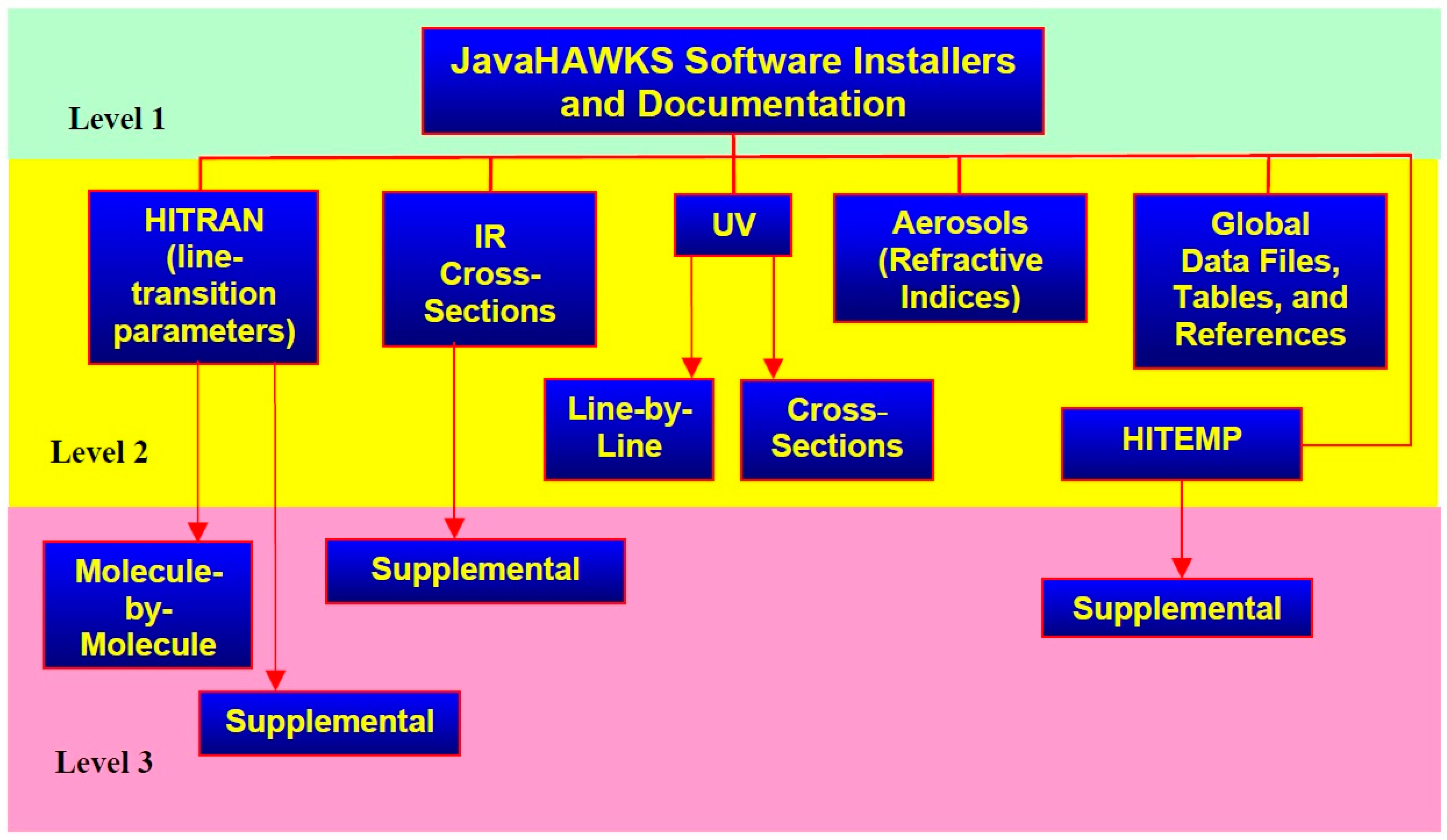
Figure 1. Structure of HITRAN spectral database [26].
Chemengineering 07 00060 g001
Figure 2. Schematics of the carbon dioxide removal system.
Chemengineering 07 00060 g002
Figure 3. 2D plot of the carbon removal device.
Chemengineering 07 00060 g003
Figure 4. Calculated absorption spectra of gas columns with pure CO2 and pure CO.
Chemengineering 07 00060 g004
Figure 5. Convergence plot of the numerical simulation.
Chemengineering 07 00060 g005
Figure 6. Flow velocity profile inside the tube.
Chemengineering 07 00060 g006
Figure 7. Two-dimensional plot of the carbon dioxide concentration profile.
Chemengineering 07 00060 g007
Figure 8. Three-dimensional plot of the carbon dioxide concentration profile.
Chemengineering 07 00060 g008
Figure 9. CO2 concentrations at the different points of the carbon removal system (1640 elements).
Chemengineering 07 00060 g009
Figure 10. CO2 concentrations at the different points of the carbon removal system (6560 elements).
Chemengineering 07 00060 g010
Table 1. Diffusion coefficients of imidazolium ionic liquid [13,28,29].
Material PropertyValueReference
Dco2-gas0.24·10−4 (m2/s)[30]
Dm1·10−9 (m2/s)[28,29]
Dco2-IL11.56·10−10 (m2/s)[13]
Disclaimer/Publisher’s Note: The statements, opinions and data contained in all publications are solely those of the individual author(s) and contributor(s) and not of MDPI and/or the editor(s). MDPI and/or the editor(s) disclaim responsibility for any injury to people or property resulting from any ideas, methods, instructions or products referred to in the content.