Article

Nanoparticle Black Ceramic Pigment Obtained by Hydrotalcite-like Compound Microwave Treatment

Escola Superior de Ceràmica de L’Alcora, ESCAL-ISEACV, 12110 L’Alcora, Castellón, Spain
*
Author to whom correspondence should be addressed.
ChemEngineering 2022, 6(4), 54; https://doi.org/10.3390/chemengineering6040054
Submission received: 30 May 2022 / Revised: 30 June 2022 / Accepted: 6 July 2022 / Published: 11 July 2022
(This article belongs to the Special Issue A Themed Issue in Honor of Prof. Dr. Vicente Rives)

Abstract

:
Development of ceramic pigments with controlled particle sizes below 1 µm is essential for the preparation of ceramic inks used in inkjet digital decoration that is currently being applied in the ceramics sector. A black ceramic pigment based on NiCoCrFe composition has been prepared using thermal decomposition of hydrotalcite-like compounds. The stoichiometry ratio between different cations was studied to obtain the blackest pigment, giving Ni0,5Co0,5CrFeO4 the better cation ratio, also the thermal treatment, comparing traditional firing in an electric furnace with microwave treatment. Samples have been characterized by X-ray diffraction, Scanning Electron Microscopy and Lab colour measurement. Microwave treatment showed the best way to obtain a pigment with spinel-type structure and a homogeneous size distribution near to 150 nm, with a high intensity and colorimetric data, reducing drastically the temperature and energy consumption to obtain a black ceramic pigment suitable to be utilized in digital ceramic inks.

1. Introduction

A ceramic pigment is a crystalline structure that gives ceramic the chromatic properties that it does not possess [1]. In the case of black ceramic pigments, the main crystalline structure used is spinel, due to its stability and inalterability when it is introduced into the composition of ceramic glazes [2]. The traditional way of preparing these pigments is the traditional route or route in the solid state, where the corresponding proportions of metal oxides and mineralizing agents are mixed, and subsequently subjected to high calcination temperatures so that the corresponding reaction occurs [3].
The use of alternative routes for the preparation of ceramic pigments has been studied in recent decades to improve reactivity, reduce the high temperatures and times used in calcination, and eliminate the use of mineralizing agents, which are harmful to the environment [4,5,6,7,8,9].
Thermal decomposition of hydrotalcite-type compounds can produce spinel [10]. An adequate formulation of these compounds allows obtaining suitable products such as ceramic pigments, with a spinel structure, lowering the temperature at which they are obtained, as well as eliminating the use of any mineralizing agent [11].
The use of new technologies for digital decoration in ceramics through inkjet printing requires the use of inks where the solid component (pigments or glazes) has a size of less than 1 micron [12]. By means of the traditional preparation of the pigments, the size obtained after the calcination process is very high (>20 microns), for which a very energetic and expensive grinding stage is necessary. Use of different soft-chemistry synthesis routes has been used to develop particle size and to avoid or minimize the grinding stage [13,14,15], also the use of thermal decomposition of hydrotalcite-type compounds reduces this size in the final product, thus minimizing the energy consumption of the grinding process because of the adequate particle size obtained [11].
Finally, the use of microwave technology in the preparation of inorganic solids has had a great boom in recent years due to the short time it takes to reach the cooking temperature, which favours the low aggregation of the material and the obtaining of very small particle sizes with the appropriate crystalline conditions [16,17,18,19].
These advantages can be used together with decomposition of hydrotalcite-like compounds to obtain well-formed and small-sized pigments suitable to be use into ceramic inks for digital ink decoration.

2. Materials and Methods

Co1-xNixFe2-yCryO4, with x and y values of 0.5 and 1, respectively, were prepared using traditional solid-state reaction and thermal decomposition of Hydrotalcite-like compound (HTLC) precursor.
For solid-state reaction, different metal oxides (Co3O4, NiO, Fe2O3 and Cr2O3) were used in industrial grade (minimum 98.5% purity), provided by Al-Farben company (Torrecid Group). Also, H3BO3 (Al-Farben 99.3%) in 5% w/w was used as flux agent
The HTLC precursors were prepared according to Kanezaki [20] procedure using 0.28 M solutions for divalent metallic cations and 0.07 M solutions for trivalent metallic cations. Solutions of NaOH 1 M and Na2CO3 0.25 M as buffer agent were also used. A variation using 0.5 M of all solutions was also studied to test the concentration effect. The solutions were prepared using CoCl2·6H2O, NiCl2·6H2O, CrCl3·6H2O and FeCl3 (Merck, 99%) and Na2CO3·10H2O (Merck, 99.5%).
Firing treatments were performed using a traditional kiln with 500 °C, 700 °C and 1000 °C with 10 °C/min heating rate and 30 min or 2 h at maximum temperature. Also, a domestic microwave oven (800 W) was used to heat an Al2O3 capsule painted inside with SiC (Figure 1). Into this capsule, different samples were located and microwaves with 800 W power were applied for times of 5, 15 and 30 min, reaching a maximum temperature of 1038 °C. Temperature reached was determined using process temperature control rings (PTCR) type ETH (temperature range 850 °C–1100 °C) from FERRO.
Analysis and characterization of the samples were performed using XRD for crystalline development (BRUKER AXS, EndeavorD4, determination angles 5–70° 2θ with acquisition time 2 s. 0.05° 2θ), TG-DTA for thermal analysis (BÄHR STA503 with Pt crucible and heating rate 5 °C/min), SEM for morphological and size distribution (JEOL7001, FED warm cathode, 15 kV and carbon sputtering) and spectrophotometer for determination of colorimetric L*a*b* coordinates (KONICA MINOLTA, CM-3600A, SpectraMagicNX d65 illumination and 2° observer).
Colour tests were prepared with an industrial transparent glossy enamel (10% ZnO in composition) with an addition in 1% w/w of synthesized ceramic pigment and fired in an industrial cycle of 1100 °C with 5 min at maximum temperature and 50 min of total firing time (cold to cold).
Table 1 summarizes the references and synthesis conditions of different samples prepared.

3. Results and Discussion

3.1. HTLC Preparation

Figure 2 shows DTA/TG of the HTLC prepared (H-crudo). Two endothermal peaks were observed at 168 °C and 327 °C with a mass loss associated (27.7%) corresponding with H2O hydration and carbonate loss, respectively. In fact, 12.3% corresponds with water loss and 15.4% with carbonate loss [11].
Figure 3 shows XRD analysis of HTLC sample (H-crude). It shows peaks corresponding with hydrotalcite, with a very low definition and crystallinity, because stoichiometry ratio used in sample preparation was M(II)/M(III) 1:2, far from the 4:1 ration in theoretical hydrotalcite, and there was no ageing time after precipitation.
The poor crystallization and lower temperature of decarbonation respect to theoretical hydrotalcite can be explained because hydrotalcite can incorporate a maximum quantity of trivalent cation. MII(OH)6 octahedra are electrically neutral, but MIII(OH)6 octahedra are positively charged, and the presence of this type of octahedra sharing edges is unstable; therefore, part of trivalent cation cannot be incorporated into the hydrotalcite structure, giving this structural deformation [10].

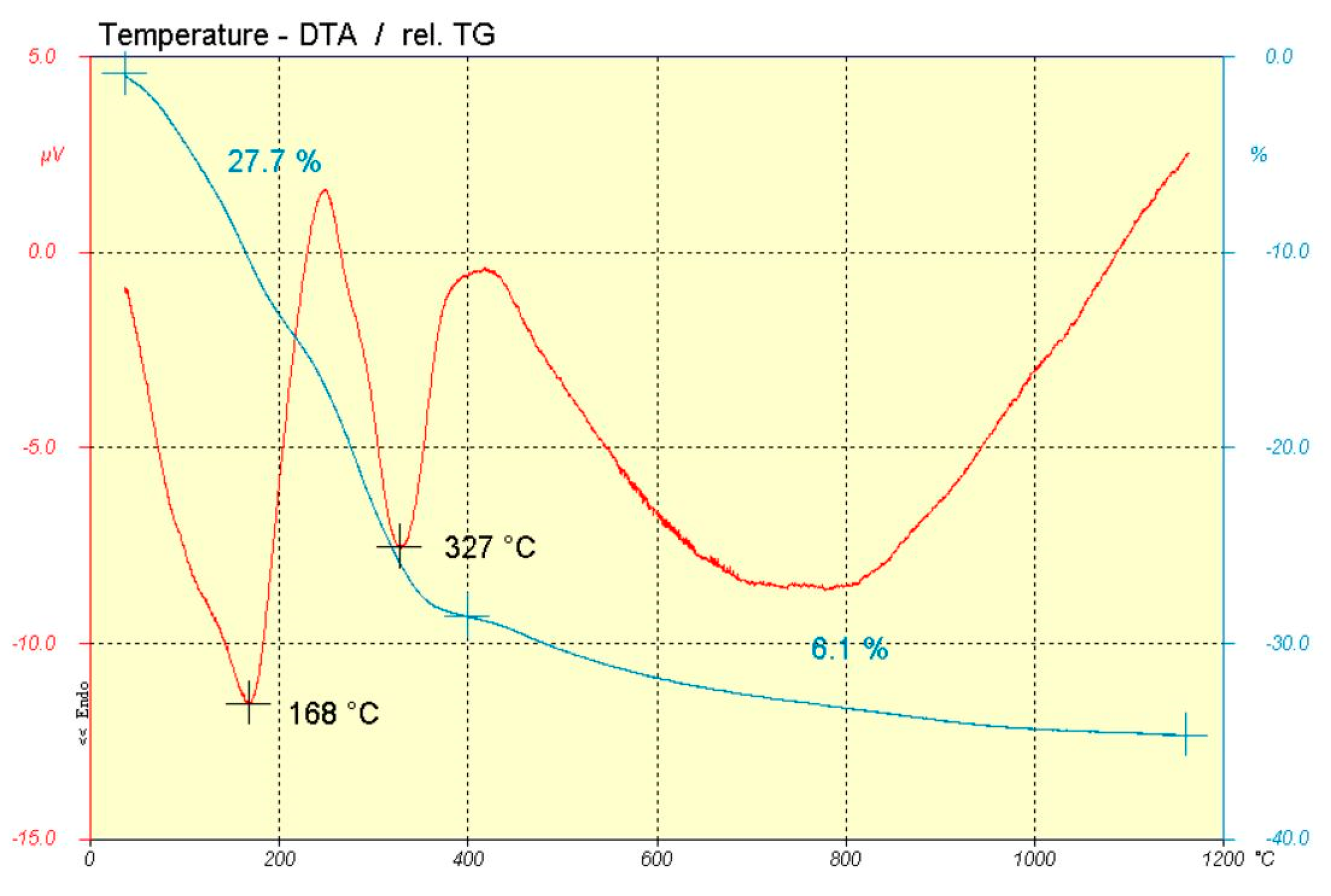
3.2. Thermal Treatment

In conventional solid state, at least 1000 °C and 120 min firing conditions are necessary to obtain a spinel phase (sample C-M6). The other firing conditions were not adequate to develop this crystalline phase. When microwave firing was used, 30 min were necessary to achieve a temperature of 1038 °C. When shorter calcination times were used, the spinel phase did not develop, since the temperatures reached were in all cases below 850 °C.
Figure 4 shows XRD analysis of sample C-M6 and C-MW3. The results were practically identical in both cases, theoretically obtaining the crystalline phase of spinel Co0.5Ni0.5FeCrO4. In fact, the crystalline phase identified in DRX pattern corresponds to spinel CoCr2O4 (JCDPS 0801668) and NiFe2O4 (JCDPS 0742081). Up to our knowledge, the reference pattern for the spinel theoretically prepared (Co0.5Ni0.5FeCrO4) does not exist, but it was clear that the solid prepared had the spinel structure and coincided with the patterns of the extreme solids of the corresponding series.
SEM micrographies (Figure 5) of these samples show well-formed aggregates where individual size was under 1 micron.
When calcining HTLCs, spinel phase formation occurred at much lower temperatures. Figure 6 shows XRD of H-M3 and H-MW1. The development of crystallization was very similar in both cases; therefore, the temperature reached with the microwave was possibly close to 500 °C. Several phases have been identified that could correspond to these peaks, namely NiO, FeO, CoO and NiCr2O4. Obviously, the peaks did not correspond to these phases, but were close to them, which gives an idea of possible intermediates made up of the different elements of the prepared composition.
Particle sizes were very low (under 100 nm) and there was no aggregation of particles, as shown in Figure 7 for sample H-MW1.
When temperatures higher than 500 °C were used, the crystalline phase of spinel Co0.5Ni0.5FeCrO4 can be observed with good crystallinity.
Figure 8 shows the XRD patterns of HM-4, HM-5, and H-M8 samples, while Figure 9 shows the XRD patterns of H-MW2 and H-MW3, respectively. As occurred in the solid-state samples calcined at 1000 °C, the target spinel was developed, being identified by the similarity with CoCr2O4 and NiFe2O4 crystalline phases, as explained above. In these cases, this phase was obtained at lower temperatures and with shorter retention times than those needed in the solid-state reaction, and with a very similar crystalline development in both cases, traditional firing and microwave treatment. Higher temperature led to better crystallization, but in all cases showing spinel formation.
In addition to the spinel phase, the mixed oxide of nickel and cobalt also appeared. This may be since these metals have the narrowest working pH ranges in which the mixed hydroxide is formed (7 to 10). Thus, it is possible that during the synthesis of hydrotalcite, the pH of the solution was below 7, giving rise to the dissolution of these metals. Subsequently, when the solution is basified again, a fractional precipitation may take place, giving rise to a mixed cobalt-nickel hydroxide. Finally, during the calcination, the spinel was obtained separately together with this mixed oxide. In all cases, it can be observed that the particle size obtained was close to 100 nm, forming aggregates in normal kiln, although with low retention time, as shown in Figure 10.
In case of using microwave kiln, there were no aggregates with a very well size distribution thanks to fast heating rates and minimum retention time during firing process, Figure 11.
Thanks to this small particle size and the non-agglomeration of these particles, a ceramic ink could be prepared for inkjet application. Preliminary test has been developed, showing the availability to obtain ceramic inks, without clogging nozzles problems.

3.3. Colour Measurement

All the prepared pigments have been applied in ceramic glazes in 1% w/w, using a transparent glaze in an industrial firing cycle of porous single firing tiles “monoporosa” pieces (1100 °C with a total cycle duration of 45 min).
The pure black colour is the one that corresponds to chromatic coordinates L = 0, a = 0 and b = 0. Of course, these values should not be reached, so the closest values will be the ones that will provide the best colour development.
The results have been compared with a commercial black pigment (Table 2), obtaining in most cases in which HTLC synthesis has been used, a higher colour yield than the commercial one. When using “colour yield” term, it is meant that the colour is closer to pure black colour (Lower values for L coordinate and a, b values closest to 0).
All the pigments prepared from the HTLC synthesis gave a very acceptable black colour performance; even the uncalcined sample had a very acceptable colour performance. In all cases where spinel has not formed after heat treatment, the developed black colour was good. This may be because the precursor obtained finished developing the spinel phase during the firing of the glazed ceramic piece, which allowed this synthesis to be used at low temperatures to obtain nanoparticulate pigments.

4. Conclusions

The main conclusions that can be drawn in this work are the following:
  • Pigments made by non-conventional routes, namely using hydrotalcite as a precursor, have better/higher colour performance than pigments made by ceramic route, when similar firing conditions are compared. In all cases, using hydrotalcite as a precursor (except crude hydrotalcite), colour performance is better than when commercial black pigment is used.
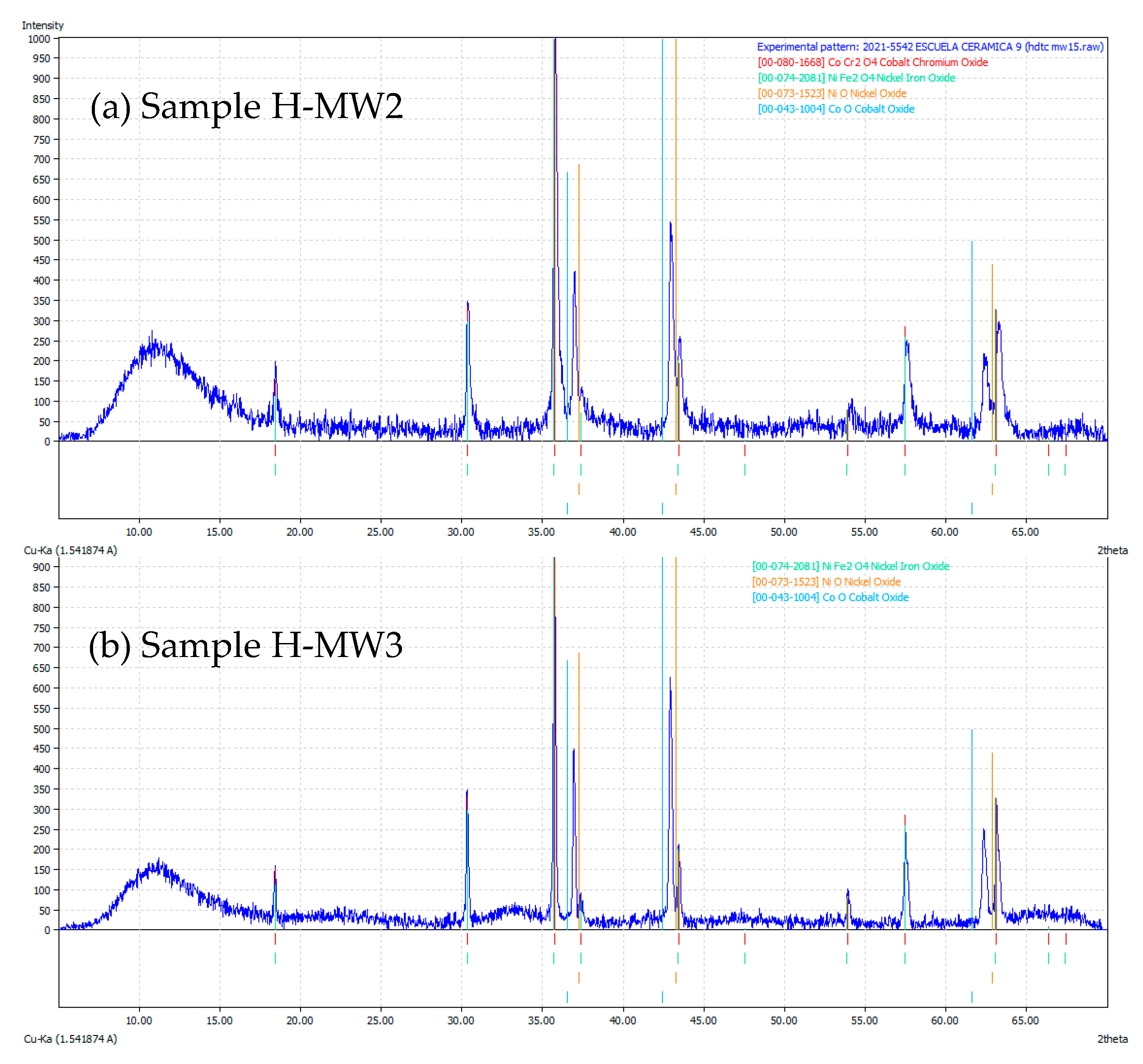
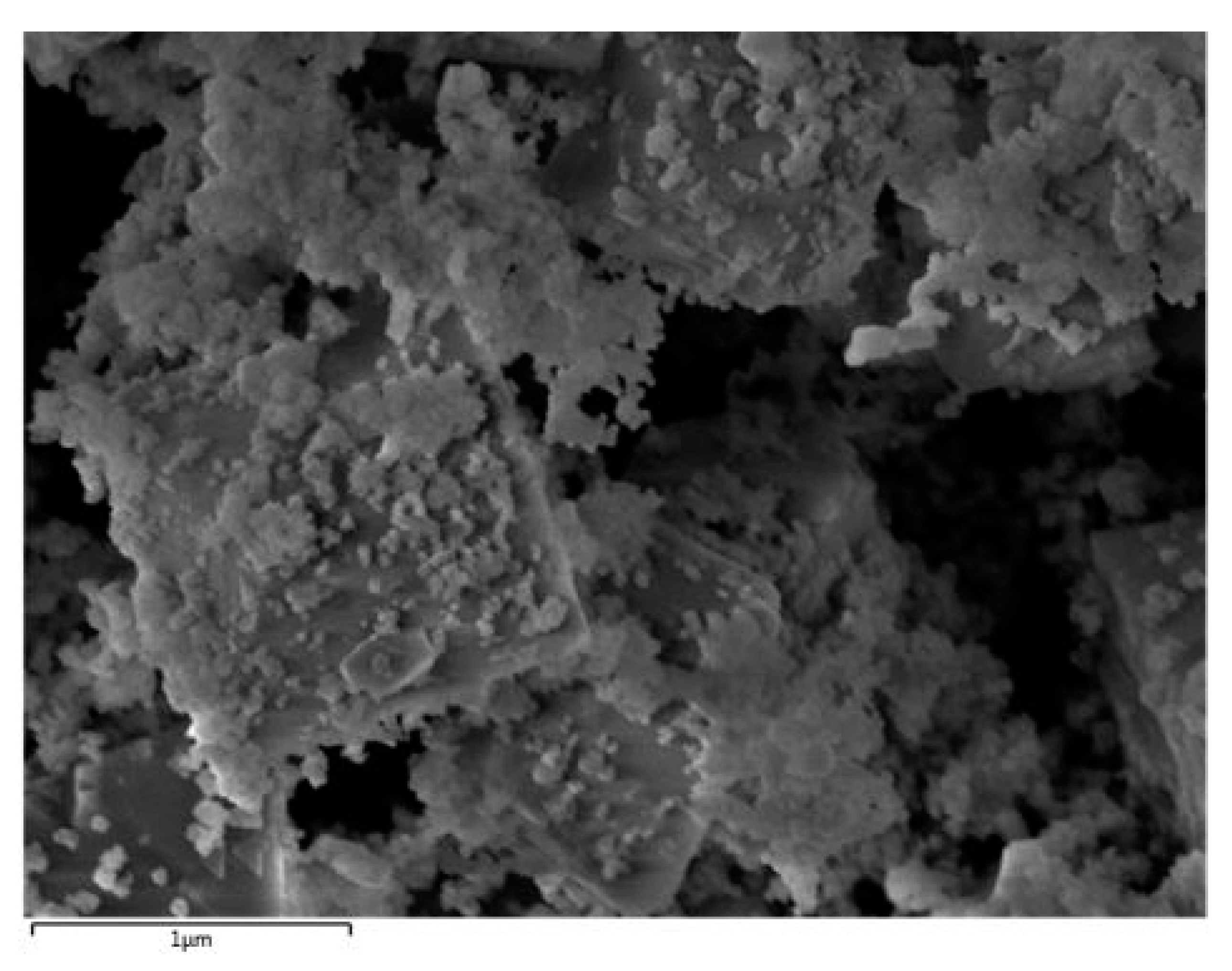
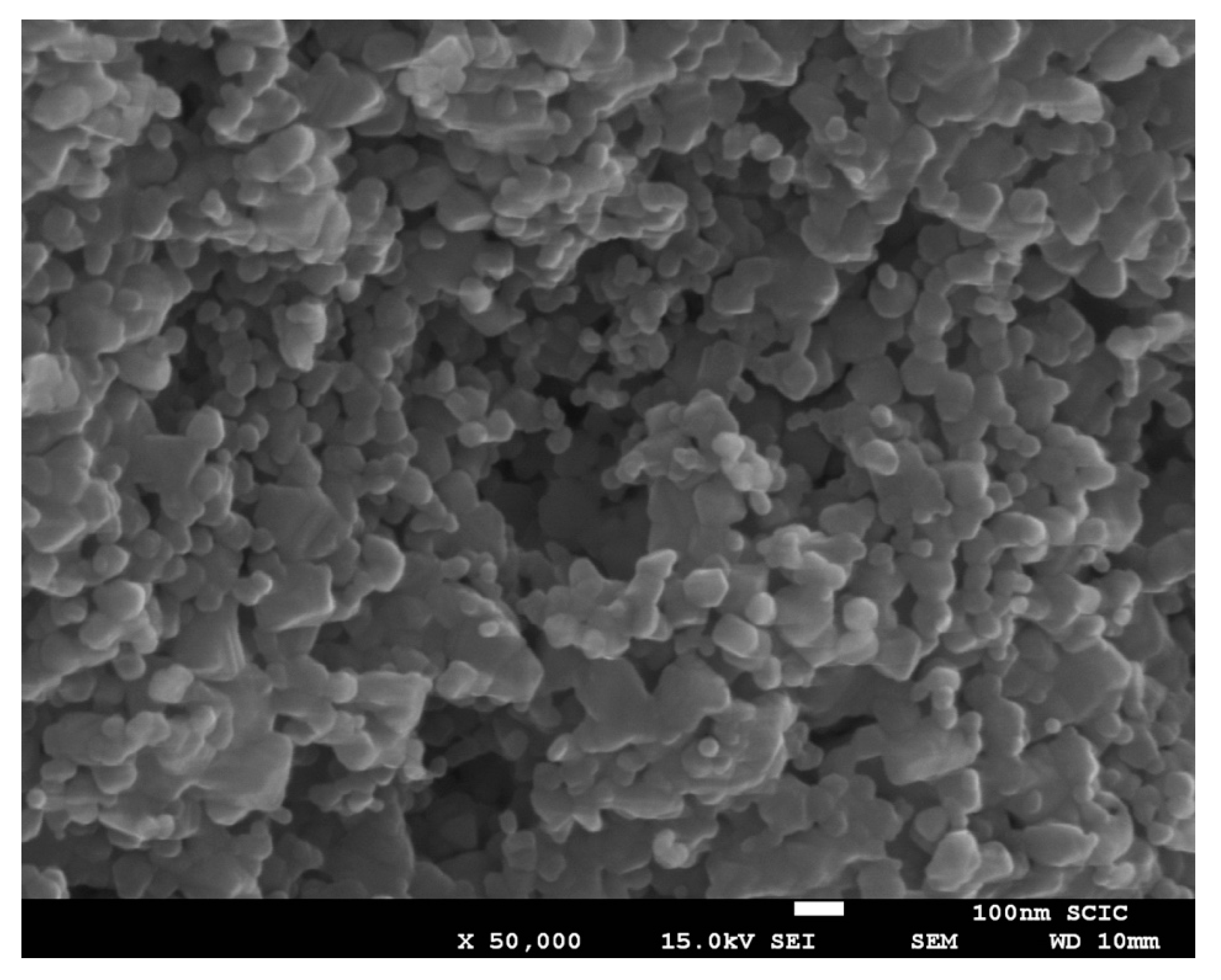
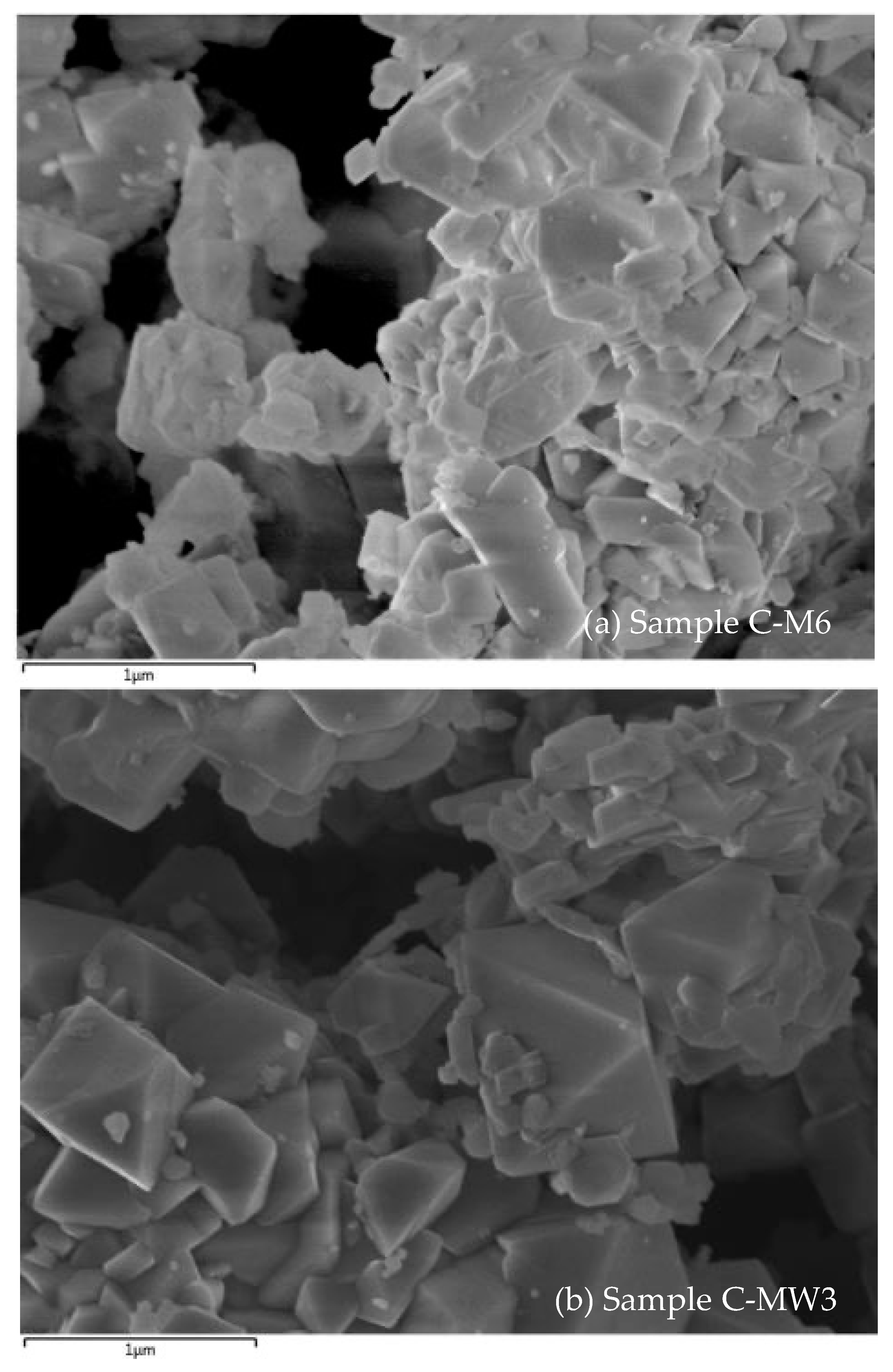
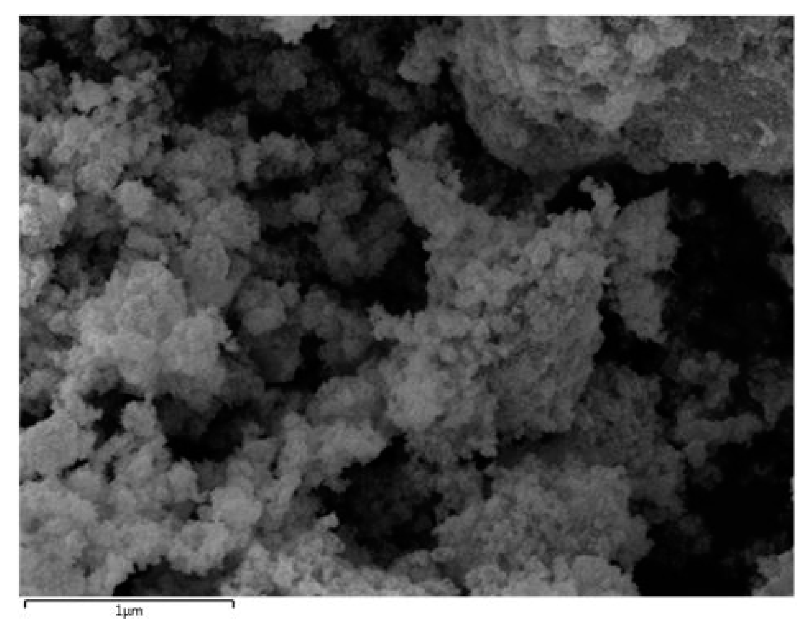
  • The use of microwave treatment reduces the final size of the primary particles due to high energy and low time firing process. When hydrotalcite precursor is used, it is enough applying 800 W for 15 min to obtain the spinel phase with the best black colour performance.
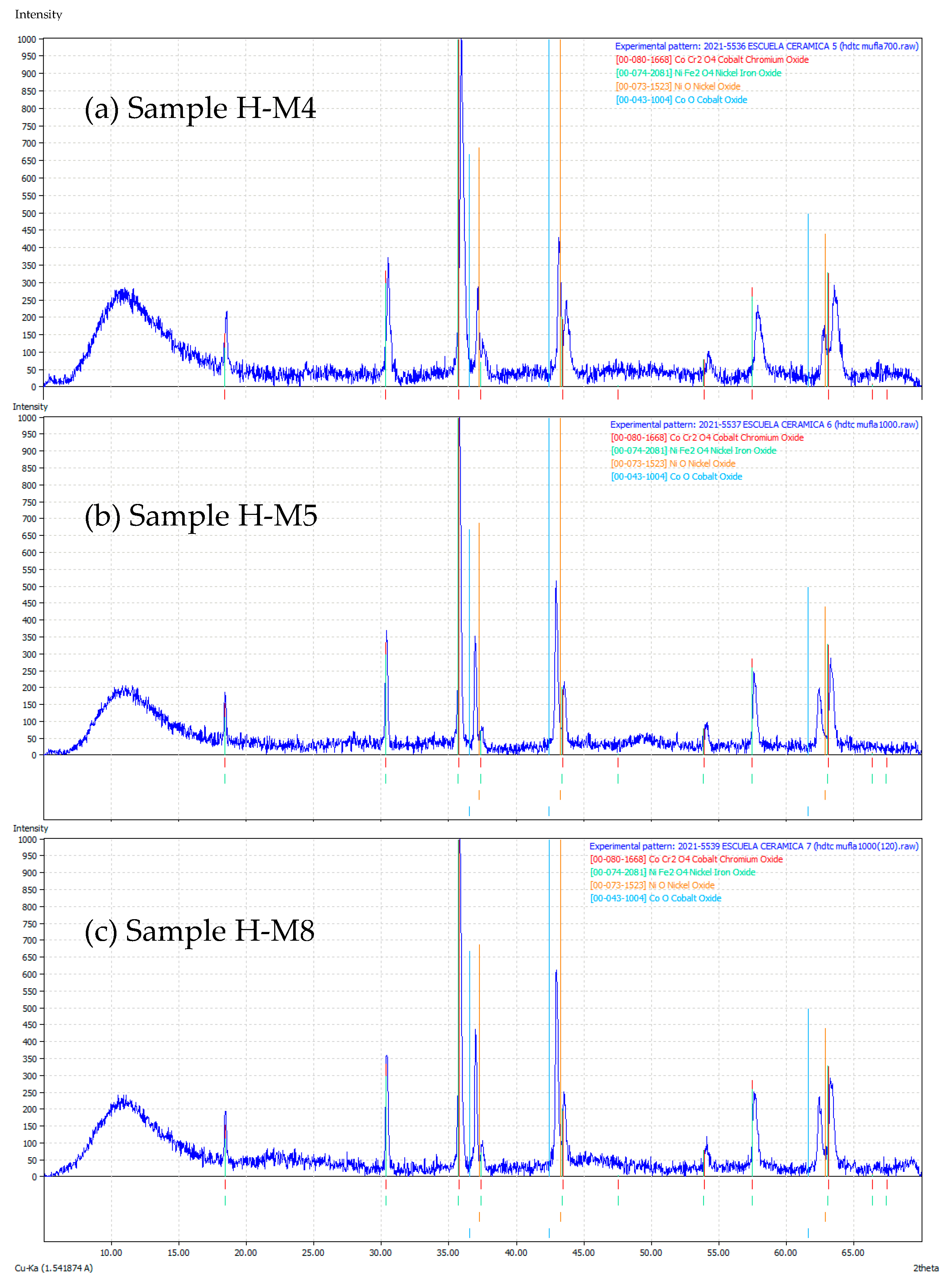
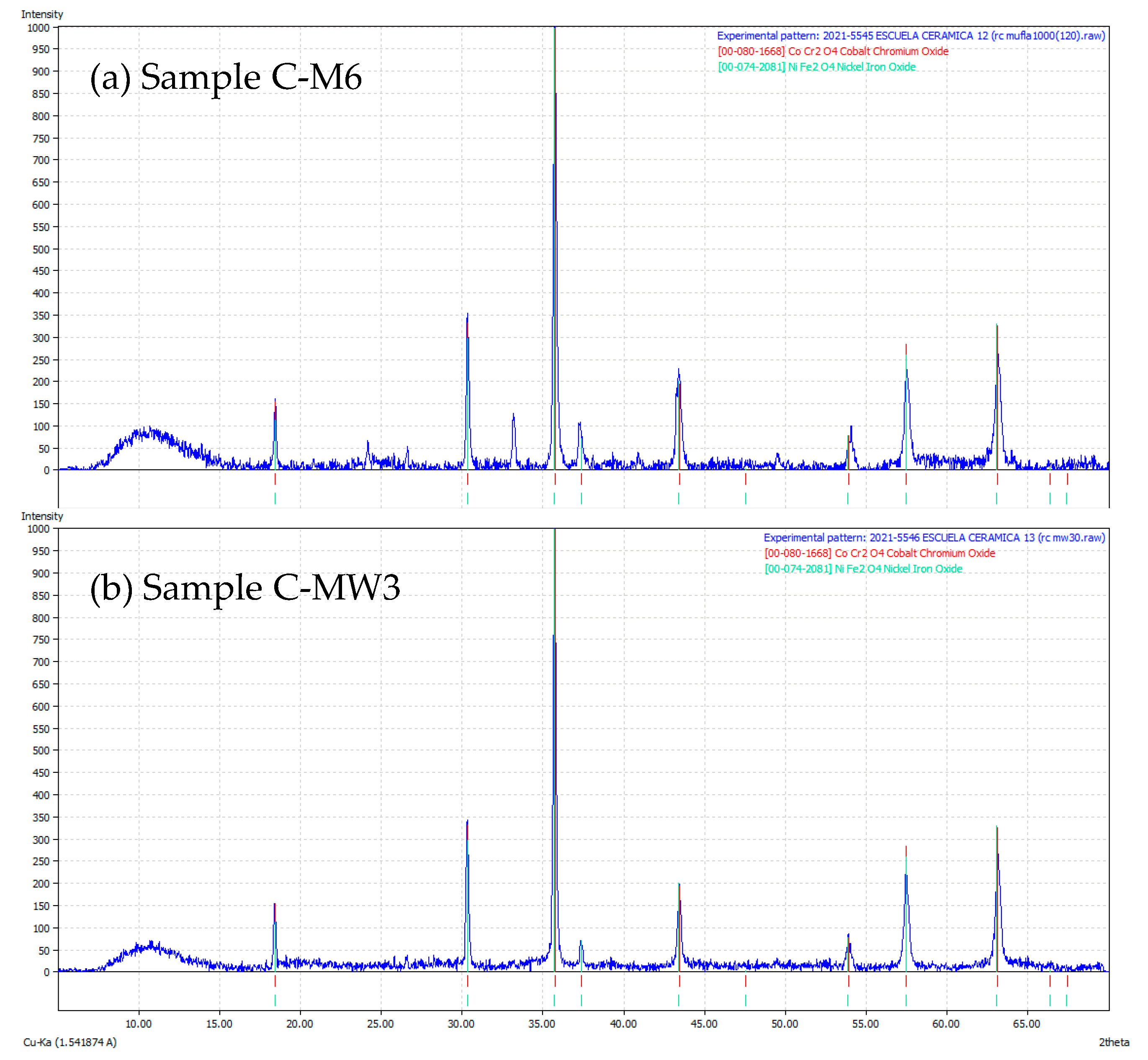
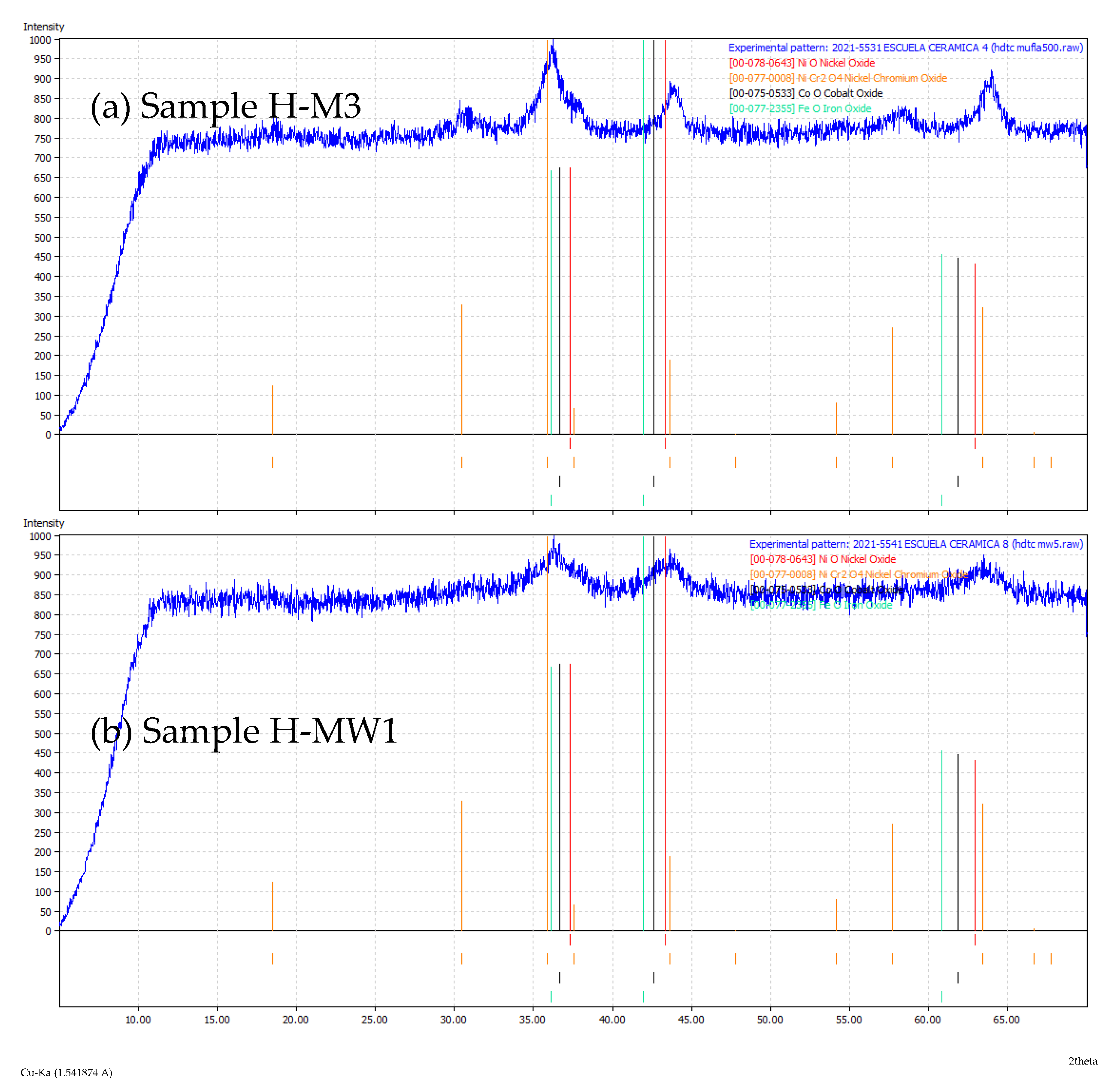
  • For samples obtained by the non-conventional synthesis route, the development of the spinel phase begins at 700 °C, while in the conventional route it is necessary to reach 1000 °C to be able to observe the development of the spinel, showing the higher reactivity of hydrotalcite precursor in front of the traditional synthesis route.
  • The developed method allows obtaining nanoparticulate ceramic pigments with a spinel structure under very favourable synthesis conditions for their industrial development.

Author Contributions

Investigation, M.O. and A.M.; Project administration, I.N.-D.; Supervision, G.P.-R. and I.N.-D.; Writing—review & editing, I.N.-D. All authors have read and agreed to the published version of the manuscript.

Funding

This research received no external funding.

Institutional Review Board Statement

Not applicable.

Informed Consent Statement

Not applicable.

Data Availability Statement

Not applicable.

Acknowledgments

Isaac Nebot-Díaz would like to thank Vicente Rives for all his teaching in the field of hydrotalcites. Without his help, the research line for the development of ceramic pigments from the thermal decomposition of hydrotalcite-type compounds would never have come true.

Conflicts of Interest

The authors declare no conflict of interest.

References

  1. Nebot-Díaz, I. Estudio y Caracterización de Compuestos Tipo Espinela MIIAl2O4 Mediante Rutas de Síntesis no Convencionales. Ph.D. Thesis, University Jaume I, Castellón, Spain, 2001. [Google Scholar]
  2. Monrós, G.; Badenes, J.A.; García, A.; Tena, M.A. El Color en los Materiales Cerámicos. In El Color de la Cerámica; Publicacions de la Universitat: Valencia, Spain, 2003; pp. 82–89. [Google Scholar]
  3. Hohemberger, J.M.; Todorova, I.; Marchal, M. Pigmentos cerámicos. In Esmaltes y Pigmentos Cerámicos; Escribano, P., Carda, J.B., Cordoncillo, E., Eds.; Faenza Editrice Ibérica: Castellón, Spain, 2001; pp. 189–242. [Google Scholar]
  4. Monrós, G.; Tena, M.A.; Escribano, P.; Cantavella, V.; Carda, J.B. Classical ceramic colours through coloidal and from alkoxides gels. J. Sol.-Gel. Sci. Tech. 1994, 2, 377–380. [Google Scholar] [CrossRef]
  5. Chavarriaga, E.A.; Jaramillo, L.J.; Restrepo, O.J. Ceramic pigments with spinel structure obtained by low temperature methods. In Characterization of Minerals, Metals and Materials; Wiley (John Wiley & Sons, Inc: Hoboken, NJ, USA, 2012; pp. 155–162. [Google Scholar]
  6. Ma, P.; Geng, Q.; Gao, X.; Yang, S.; Liu, G. CuCr2O4 spinel ceramic pigments synthesized by sol-gel self-combustion method for solar absorber coatings. J. Mater. Eng. Perf. 2016, 25, 2814–2823. [Google Scholar] [CrossRef]
  7. Betancour-Granados, N.; Restrepo-Baena, O.J. Flame spray pyrolysis of ceramic nanopigments CoCr2O4: The effect of key variables. J. Eur. Cer. Soc. 2017, 37, 5051–5056. [Google Scholar] [CrossRef]
  8. El Jabbar, Y.; Lakhlifi, H.; El Ouatib, R.; Er-Rakho, L.; Guillemet-Fritsch, S.; Durand, B. Preparation and characterization of green nano-sized cramic pigmens with the spinel structure AB2O4 (A=Co, Ni and B=Cr, Al). Solid State Commu. 2021, 334, 114394. [Google Scholar] [CrossRef]
  9. Paborji, F.; Afarini, M.S.; Arabi, A.M.; Ghahari, M. Solution combustion synthesis of FeCr2O4 powders for pigment applications: Effect of fuel type. Int. J. Appl. Cer. Tech. 2022; in press. [Google Scholar] [CrossRef]
  10. Nebot-Díaz, I.; Rives, V.; Rocha, J.; Carda, J.B. Thermal decomposition study of hydrotalcite-like compounds. Bol. Soc. Esp. Cer. Vidr. 2002, 41, 411–414. [Google Scholar] [CrossRef]
  11. Rives, V.; Pérez-Bernal, M.E.; Ruano-Casero, R.J.; Nebot-Díaz, I. Development of a black pigment form non stoichiometric hydrotalcites. J. Eur. Cer. Soc. 2012, 32, 975–987. [Google Scholar] [CrossRef]
  12. Nebot-Díaz, I.; Dal Corso, P.L. Digital Ceramic Decoration, an Introduction; ATC: Castellón, Spain, 2017. [Google Scholar]
  13. Li, X.; Wang, Q.K.; Wang, C.; Zhang, W.J.; Yang, Y.L.; Liu, K.; Wankg, Y.Q.; Chang, Q.B. Ultrafine Z-ZrSiO4 pigment prepared by a bottom-up approach: Particle size evolution and chromatic properties. Adv. Powder Technol. 2021, 32, 3934–3942. [Google Scholar] [CrossRef]
  14. Molinari, C.; Conte, S.; Zanelli, C.; Ardite, M.; Cruciani, G.; Dondi, M. Ceramic pigments and dyes beyond the inkjet revolution: From technological requirements to constraints in colorant design. Ceram. Int. 2020, 46, 21839–21872. [Google Scholar] [CrossRef]
  15. Tang, Q.; Zhu, H.X.; Chen, C.; Wang, Y.X.; Zhu, Z.G.; Wu, J.Q.; Shis, W.H. Preparation and characterization of nanoscale cobalt blue pigment for ceramic inkjet printing by sol-gel self-propagating combustion. Mater. Res. Ibero-Am. J. Mater. 2017, 20, 1340–1344. [Google Scholar] [CrossRef] [Green Version]
  16. Obata, S.; Kato, M.; Yokohama, H.; Iwata, Y.; Kikumoto, M.; Sakurada, O. Synthesis of nano CoAl2O4 pigment for ink-jet printing to decorate porcelain. J. Cer. Soc. Jpn. 2011, 119, 208–213. [Google Scholar] [CrossRef] [Green Version]
  17. Veronesi, P.; Leonelli, C.; Bondioli, F. Energy efficiency in the microwave-assisted solid-state synthesis of cobalt-aluminate pigment. Technologies 2017, 5, 42. [Google Scholar] [CrossRef] [Green Version]
  18. Trujillano, R.; Nieto, D.; Rives, V. Microwave-assisted synthesis of Ni, Zn layered double hydroxysalts. Microporous Mesoporous Mater. 2017, 253, 129–136. [Google Scholar] [CrossRef]
  19. Trujillano, R.; González-García, I.; Morato, A.; Rives, V. Controlling the synthesis conditions for tuning the properties of hydrotalcite like materials at the nano scale. Chemengineering 2018, 2, 31. [Google Scholar] [CrossRef] [Green Version]
  20. Kanezaki, E. Thermal behaviour of the hydrotalcite-like layered structure of Mg and Al layered double hydroxides with interlayer carbonate by means of in situ powder HTXRD and DTA/TG. Solid State Ion. 1998, 196, 279–284. [Google Scholar] [CrossRef]
Figure 1. Capsule for microwave kiln painted with SiC.
Chemengineering 06 00054 g001
Figure 2. DTA (red line) and TG (blue line) of HTLC sample.
Chemengineering 06 00054 g002
Figure 3. XRD of HTLC sample prepared (red lines correspond to hydrotalcite XRD pattern JCDP 010890460).
Chemengineering 06 00054 g003
Figure 4. XRD of samples C-M6 (a) and C-MW3 (b) (red lines correspond to CoCr2O4 XRD pattern (JCDPS 0801668) and light blue ones to NiFe2O4 (JCDPS 0742081)).
Chemengineering 06 00054 g004
Figure 5. SEM micrograph of samples C-M6 (a) and C-MW3 (b).
Chemengineering 06 00054 g005
Figure 6. XRD of samples H-M3 (a) and H-MW1 (b) (red lines correspond to NiO XRD pattern (JCDPS 0780643), orange to NiCr2O4 (JCDPS 0770008), dark blue to CoO (JCDPS 0750533) and light green to FeO (JCDPS 0772355)).
Chemengineering 06 00054 g006
Figure 7. SEM micrograph of sample H-MW1.
Chemengineering 06 00054 g007
Figure 8. XRD patterns of samples H-M4 (a), H-M5 (b) and H-M8 (c) (red lines correspond to CoCr2O4 XRD pattern (JCDPS 0801668), light green to NiFe2O4 (JCDPS 0742081), and orange to NiO (JCDPS 0731523)).
Chemengineering 06 00054 g008
Figure 9. XRD patterns of samples H-MW2 (a) and H-MW3 (b) (red lines correspond to CoCr2O4 XRD pattern (JCDPS 0801668), light green to NiFe2O4 (JCDPS 0742081), and orange to NiO (JCDPS 0731523)).
Chemengineering 06 00054 g009
Figure 10. SEM micrograph of sample H-M5.
Chemengineering 06 00054 g010
Figure 11. SEM micrograph of sample H-MW2.
Chemengineering 06 00054 g011
Table 1. References of prepared samples.
ReferenceSynthesis MethodFiringTemperature (°C)Remaining Time at Max. T (min)
C-crudeSolid stateNo firing--
C-M1Solid stateNormal kiln50030
C-M2Solid stateNormal kiln70030
C-M3Solid stateNormal kiln100030
C-M4Solid stateNormal kiln500120
C-M5Solid stateNormal kiln700120
C-M6Solid stateNormal kiln1000120
C-MW1Solid stateMicrowave<8505
C-MW2Solid stateMicrowave<85015
C-MW3Solid stateMicrowave103830
H-crudeHTLCNo firing----------------------------
H-M1HTLCNormal kiln30030
H-M2HTLCNormal kiln40030
H-M3HTLCNormal kiln50030
H-M4HTLCNormal kiln70030
H-M5HTLCNormal kiln100030
H-M6HTLCNormal kiln500120
H-M7HTLCNormal kiln700120
H-M8HTLCNormal kiln1000120
H-MW1HTLCMicrowave<8505
H-MW2HTLCMicrowave<85015
H-MW3HTLCMicrowave103830
Table 2. L*a*b* colorimetric coordinates of different pigments studied.
ReferenceLab
C-crude44.47−2.727.6
C-M142.85−1.886.74
C-M238.99−0.844.91
C-M336.360.143.01
C-M442.78−1.976.51
C-M541.02−1.795.44
C-M637.191.133.70
C-MW143.74−2.476.98
C-MW236.721.853.03
C-MW336.741.651.71
H-crude36.621.121.47
H-M133.370.930.76
H-M235.750.55−0.18
H-M335.360.54−0.16
H-M432.290.930.72
H-M531.301.38−0.03
H-M636.650.761.12
H-M735.170.980.94
H-M829.401.150.04
H-MW139.091.040.61
H-MW232.121.120.32
H-MW332.251.00−2.32
Commercial36.041.36−1.01
Publisher’s Note: MDPI stays neutral with regard to jurisdictional claims in published maps and institutional affiliations.

