Article

Fluid-Structure Interaction in Coronary Stents: A Discrete Multiphysics Approach

by
Adamu Musa Mohammed
1,2,*,
Mostapha Ariane
3 and
Alessio Alexiadis
1,*
1
School of Chemical Engineering, University of Birmingham, Birmingham B15 2TT, UK
2
Department of Chemical Engineering, Faculty of Engineering and Engineering Technology, Abubakar Tafawa Balewa University, Bauchi 740272, Nigeria
3
Department of Materials and Engineering, Sayens—University of Burgundy, 21000 Dijon, France
*
Authors to whom correspondence should be addressed.
ChemEngineering 2021, 5(3), 60; https://doi.org/10.3390/chemengineering5030060
Submission received: 29 June 2021 / Revised: 31 August 2021 / Accepted: 3 September 2021 / Published: 8 September 2021

Abstract

:
Stenting is a common method for treating atherosclerosis. A metal or polymer stent is deployed to open the stenosed artery or vein. After the stent is deployed, the blood flow dynamics influence the mechanics by compressing and expanding the structure. If the stent does not respond properly to the resulting stress, vascular wall injury or re-stenosis can occur. In this work, a Discrete Multiphysics modelling approach is used to study the mechanical deformation of the coronary stent and its relationship with the blood flow dynamics. The major parameters responsible for deforming the stent are sorted in terms of dimensionless numbers and a relationship between the elastic forces in the stent and pressure forces in the fluid is established. The blood flow and the stiffness of the stent material contribute significantly to the stent deformation and affect its rate of deformation. The stress distribution in the stent is not uniform with the higher stresses occurring at the nodes of the structure. From the relationship (correlation) between the elastic force and the pressure force, depending on the type of material used for the stent, the model can be used to predict whether the stent is at risk of fracture or not after deployment.

1. Introduction

Atherosclerosis is a condition where arteries become clogged with fatty substances called plaque. The plaque is deposited on the arterial wall, and this leads to the narrowing of the artery and subsequently obstruction of the blood flow known as stenosis. This obstruction hinders the smooth transportation of blood through these arteries and consequently poses a serious health problem. When atherosclerosis affects an artery that transports oxygenated blood to the heart, it is called coronary artery disease. Coronary artery disease is the most common heart disease that becomes the leading cause of death globally. Worldwide, it is associated with 17.8 million death annually [1]. The healthcare service for coronary artery disease poses a serious economic burden even on the developed countries, costing about 200 dollars annually in the United States.
The obstruction of the flow line (stenosis) also alters the blood flow regime and causes a deviation from laminar to turbulence, or even transitional flow [2,3], a situation that signifies severely disturbed flow. Studies were carried out on the types of plaque and its morphologies as well as the flow type and its consequence [4,5,6,7] that occurred in human arteries. Although the disease is deadly, it is preventable. Therefore, it is paramount to manage or prevent it in order to restore normal blood flow in the affected artery.
One of the ways of managing coronary artery disease is restoring normal blood flow or revascularization in a patient with a severe condition using the percutaneous coronary intervention (with stent) [8]. Coronary stents are tubular scaffolds that are deployed to recover the shrinking size of a diseased (narrowed) arterial segment [9] and stenting is a primary treatment of a stenosed artery that hinders smooth blood flow [10].
The stents used in clinical practice come in differential geometry and design which implies varying stress distribution within the local hemodynamic environment as well as on the plaque and artery [11,12]. The stent structure also induces different levels of Wall Shear Stress (WSS) on the wall of the artery [9,13]. Many cases of stent failure due to unbearable stress were reported and therefore, a careful study on how these stresses are distributed is needed. In fact, stent fracture or failure often occurs after stent implantation, and it can be avoidable if the mechanical property and the performance of the material are predicted. An ideal stent should provide good arterial support after expansion by having high radial strength. It should also cause minimal injury to the artery when expanded and should have high flexibility for easy maneuvering during insertion [14,15].
Studies on the different stent designs and how they affect their mechanical performance were reported [12,13]. Stent deformation and fracture after implantation were also investigated [16,17,18,19,20]. Moreover, numerical modelling and simulations were also used in studying coronary stent and stent implantation. For instance, Di Venuta et al., 2017 carried out a numerical simulation on a failed coronary stent implant on the degree of residual stenosis and discovered that the wall shear stress increases monotonically, but not linearly with the degree of residual stenosis [8]. Simulation of hemodynamics in a stented coronary artery and for in-stent restenosis was performed by [21,22].
With a few exceptions [23,24,25], the mechanical properties of the stent and the blood fluid dynamics around the stent were studied separately. In this work, we propose a single Fluid-Structure Interaction (FSI) model that calculates the stress on the stent produced by the pulsatile flow around the stent; both the stent mechanics and the blood hydrodynamics are calculated at the same time. The model is based on the Discrete Multiphysics (DMP) framework [26], which has been used in a variety of FSI problems in biological systems such as the intestine [27], aortic valve [28,29], the lungs [28], deep venous valves [30,31]. In this study, therefore, we use the DMP framework to develop an FSI 3D coronary stent model coupled with the blood hydrodynamics and analyse the mechanical deformations produced by the flow hydrodynamics.

2. Methods

2.1. Discrete Multiphysics

Discrete Multiphysics framework combines together particle-based techniques such as Smooth Particle Hydrodynamics (SPH) [32,33], Discrete Element Method (DEM) [34,35], Lattice Spring Model (LSM) [36,37], PeriDynamics (PD) [38], and even Artificial Neural Networks (ANN) [39,40]. In this case, the model couples SPH and LSM. The computational domain is divided into the liquid domain and the solid domain. The liquid domain represents the blood, and it is modelled with SPH particles; the solid domain represents the stent and the arterial walls and it is modelled with LSM particles. Details on SPH theory can be found in [41], and of LSM in [42,43]. Here a brief introduction of the equations used in SPH and LSM is provided.

2.2. Smooth Particle Hydrodynamics (SPH)

This section provides a basic introduction to SPH; additional details can be found in [41,44]. The general idea of SPH is to approximate a partial differential equation over a group of movable computational particles that are not connected over a grid or a mesh [37]. Newton’s second law is integrated to give an approximate motion of the particles characterized by their own properties such as mass, velocity, pressure, and density expressed by the fundamental identity:
f ( r ) = f ( r ) δ ( r r ) d r ,
where f ( r ) is a generic function defined over the volume, r is the position where the property is measured, and δ ( r ) is the delta function which is approximated by a smoothing (Kernel) function W over a characteristic with h (smoothing length). In this study, we use the so-called Lucy Kernel [41]. This approximation gives rise to
f ( r ) f ( r ) W ( r r , h ) d r ,
which can be discretised over a series of particles of mass m = ρ(r)dr obtaining
f ( r ) i m i ρ i f ( r i ) W ( r r i , h ) ,
where m i and ρ i are the mass and density of the ith particles, and i ranges over all particles within the smoothing Kernel. Using this approximation, the Navier-Stoke equation can be discretised over a series of particles to obtain:
m i d v i d t = j m i m j ( P i ρ i 2 + P j ρ j 2 + Π i , j ) j W i , j + f i ,
where v is the particle velocity, t the time, m is the mass, ρ the density, and P the pressure associated with particles i and j . The term fi is the volumetric body force acting on the fluid and Πi,j introduces the viscous force as defined by [45]. An equation of state is required to relate pressure and density. In this paper, Tait’s equation of state is used:
P ( ρ ) = c 0 ρ 0 7 [ ( ρ ρ 0 ) 7 1 ] ,
where c 0 and ρ 0 are a reference sound speed and density. To ensure weak compressibility, c 0 is chosen to be at least 10 times larger than the highest fluid velocity.

2.3. Lattice Spring Model (LSM)

Elastic objects can be simulated using lattice spring models. As already discussed in [29], the main element of this model is composed of a mass point and linear spring which exerts forces at the nodes connected by a linear spring and placed on a lattice. Any material point of the body can be referred to by its position vector r = ( x , y , z ) [46]; when the body undergoes deformation its position changes and the displacement is related to the applied force as:
F = k ( l l 0 )
where F is the force, l 0 is the initial distance between two particles, l is the instantaneous distance, and k the spring constant (or Hookean constant).
According to [42], in a regular cubic lattice structure, the spring constant is related to the bulk modulus of the material by
K = 5 3   k l 0
and
E = 3 2   K
where K is the bulk modulus, E the young modulus, l 0 is the initial particle distance and k the spring constant.
From Equations (7) and (8) the spring constant is then related to the Young modulus of the material by
k = E l 0 2.5 .

3. Model and Geometry

A three-dimensional stent model including blood flow hydrodynamics and stent mechanics is developed. The model simulates the blood dynamics in a 3D channel similar to a coronary artery with a 1.5 × 10 3   m internal radius, including a PS-shape stent of 4 struts in the x-direction and 4 struts in the z-direction (circumference). The stent has a thickness of 100   μ m , and 7.5 mm length, the size that is within the range of the stent used in clinical practice [47]. We choose a PS-Shaped because it performs better compare to most commercially shaped stents as reported by [25].
The geometry was created using CAD. From the geometry, we used MATLAB script to generate the coordinate of the computational particles as the points are created with MATLAB (details can be found in [29]). The script also generates a LAMMPS data file for the simulations and the simulations were run with LAMMPS, an open-source software [48]. The three-dimensional model consists of 1,862,804 particles: 1,609,452 particles for the fluid, 46,336 particles for the stent and 207,016 particles for the arterial wall. The fluid has a density ( ρ ) of 1056 kg m−3 and viscosity ( μ ) 0.0035 Pa∙s. Figure 1 shows the section geometry of the stent within and outside the arterial wall. Local acceleration term g 0 was included to force the fluid to flow at a particular velocity. The inclusion of the local velocity is due to the unsteady or pulsatile flow existing in the cardiovascular system [49]. Womersley parameter α, which is the ratio of unsteady force to viscous force, was used in the model to induce the velocity profile of the flow. The particle spacing is 3.33 × 10 5 m. The optimal spacing value is obtained after several simulations with different particle spacings to make sure the results are independent of the particle resolution. Stress and deformation and other postprocessing calculations were done with the visualization software OVITO [50]. The arterial wall is assumed to be rigid with a no-slip condition [25] whereas the stent is elastic. The no-slip and no penetration boundary condition is imposed at the interface of the solid-liquid interaction as discussed in our previous work [51]. Figure 1a,b shows a section of the solid geometry which includes the stent and the wall and the complete geometry of the stent respectively.
The flow is being driven by a sinusoidal (pulsatile) acceleration ( G ) of the flow in the axial direction to simulate a heartbeat of 60/min with a period ( T ) of 1 s; the same approach was used in a previous publication [29], where the reader can find more details.
Eighteen (18) sets of simulations were run with a combination of v 1 v 3 and k 1 k 6 (see Section 4 for reasons). The University of Birmingham Bluebear (super-computer) was used for the computation (simulation) where ninety (90) processors were assigned for 72 h to run each simulation. For each simulation, a dump file (result file) of 9–10 GB of memory is obtained.
To better understand the hydrodynamics of the fluid and to be able to access the deformation of the stent, the discussion is carried out in terms of dimensionless numbers. According to the Buckingham π theorem, a physically meaningful equation involving n physical variables can be rewritten in terms of a set of p = nk dimensionless parameters Π1, Π2, …, Πp, where k is the number of physical dimensions involved. In this case, the physiochemical properties of blood are constant, and the geometry is fixed. Therefore, we want to express the resulting stress on the stent as a function f of the type
σ = f ( P , d , E ) ,
where s [kg m−1s−2] is the stress on the stent, P [kg m−1s−2] the dynamic pressure in the fluid (the force exerted by the fluid to the stent depends on P), d [m] a characteristic length of the stent (here, we use the thickness of the stent), and E [kg m−1s−2] the Young Modulus.
In this case, the dynamic pressure can be written in terms of fluid average velocity v and density r,
P = ρ v 2 ,
Moreover, k [kg s−2] and E are related in Equation (9). Therefore, assuming that the lattice spacing is fixed, we can replace Equation (10) with
σ = f ( ρ , v , d , k ) ,
Since we have 5 variables and 3 units, we can rewrite Equation (12) based on two dimensionless numbers
Π 2 = φ ( Π 1 ) .
The first dimensionless number can be defined as
Π 1 = k ρ v 2 d   [ elastic   forces   that   contrast   deformation   ( in   the   solid ) ] [ pressure   forces   that   tend   to   deform   the   stent   ( from   the   liquid ) ]
Knowing the typical ranges of E and d for the stent, and ρ and v for the blood, we can calculate the typical range of Π1. The second parameter Π2 can be defined as
Π 2 = σ   d k .
We can have different types of Π2 according to the type of stress we use in Equation (15). The stress tensor has 6 independent components that can be composed in different ways to provide different types of information. One possibility is to use the Frobenius norm.
σ F = σ x x 2 + σ y y 2 + σ z z 2 + 2 σ x y 2 + 2 σ x z 2 + 2 σ y z 2
In this case, we have a Π2 based on the Frobenius norm
Π 2 F = σ F   d k .
that expresses, in dimensionless form, the total stress in the stent. Another possibility is the von Mises stress
σ V = 1 2 [ ( σ x x σ y y ) 2 + ( σ y y σ z z ) 2 + ( σ z z σ x x ) 2 ] + 3 ( σ x y 2 + σ y z 2 + σ z x 2 )
which provides another Π2 number defined as
Π 2 V = σ V   d k .
Physically, ΠF2 and ΠV2 are dimensionless stresses and can have both a local form Π2 (x, y, z) (when we calculate them at each x, y, z position), and a global form <Π2> (when we average them over the whole stent). Table 1 shows the parameters used in the simulation.

4. Results and Discussion

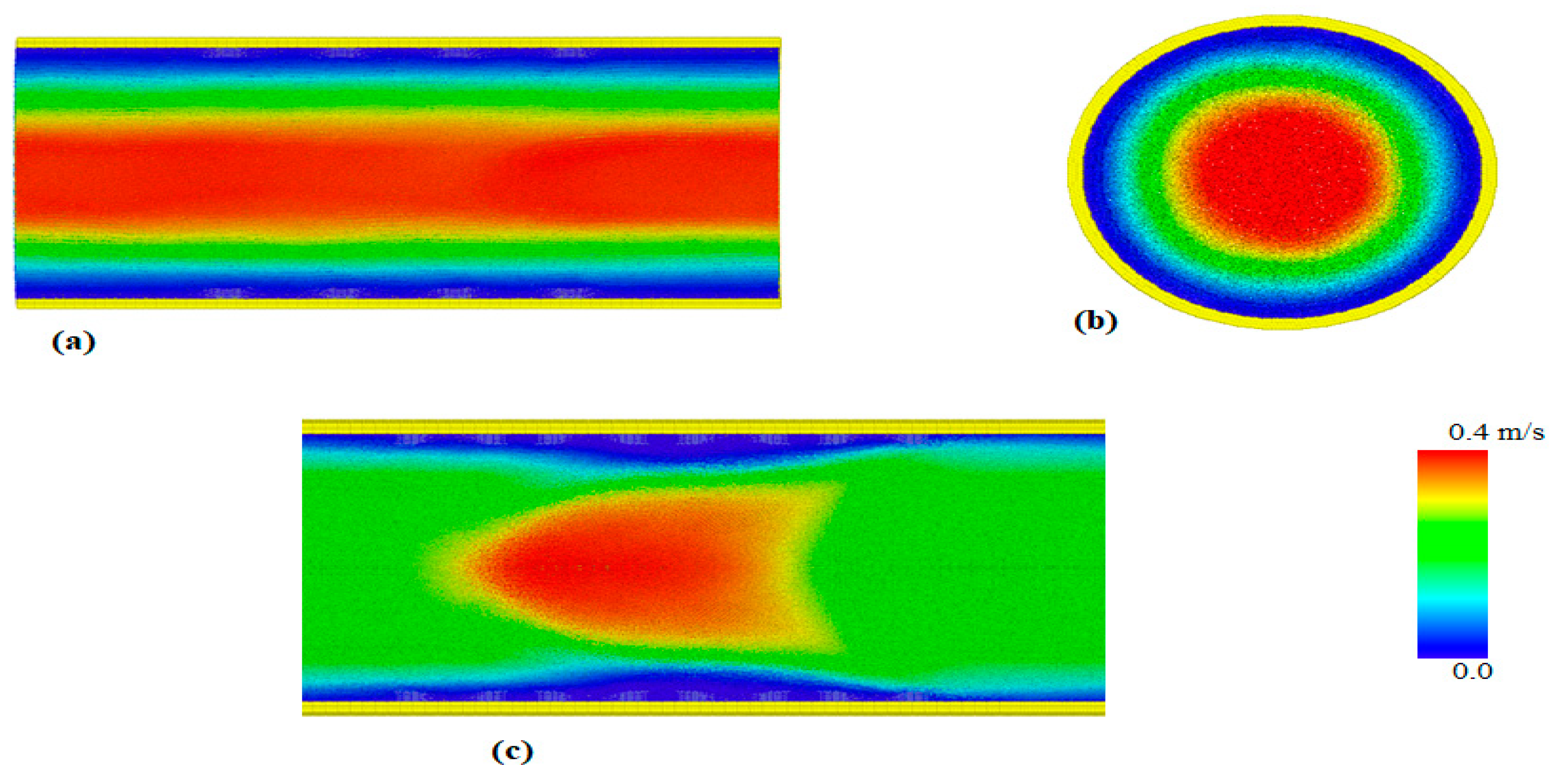
Three flow velocities of 0.4   ms 1 , 0.23   ms 1 and 0.16   ms 1 were chosen to represent the normal coronary artery and the baseline flow, respectively. The value of k was chosen from 0.5   to   5 to cover materials with the lowest to highest Young modulus. The blood flow velocity observed within the stent ranges from 0.23   ms 1 to 0.4   ms 1 , whereas the minimum flow velocity which may occur due to stenosis is 0.16   ms 1 and taken to be the baseline [52]. The velocity profile at different viewpoints is shown in Figure 2.
The dimensionless von Mises stress is shown in Figure 3 for two stents at different Π 1 . Different values of Π 1   means different k   and v .   It is shown that the stress is more severe at the nodes (joints) with higher stress at higher Π 1 as clearly shown in Figure 3b. This may lead to potential stent failure (rapture) at the joins or size change of the stent resulting from compression or expansion. The expansion characteristics of a stent are the main causes of vascular wall injuries [53]. Either of these conditions (failure or size change) will cause severe pain and damage to the patient and lead to restenosis and or stent redeployment.
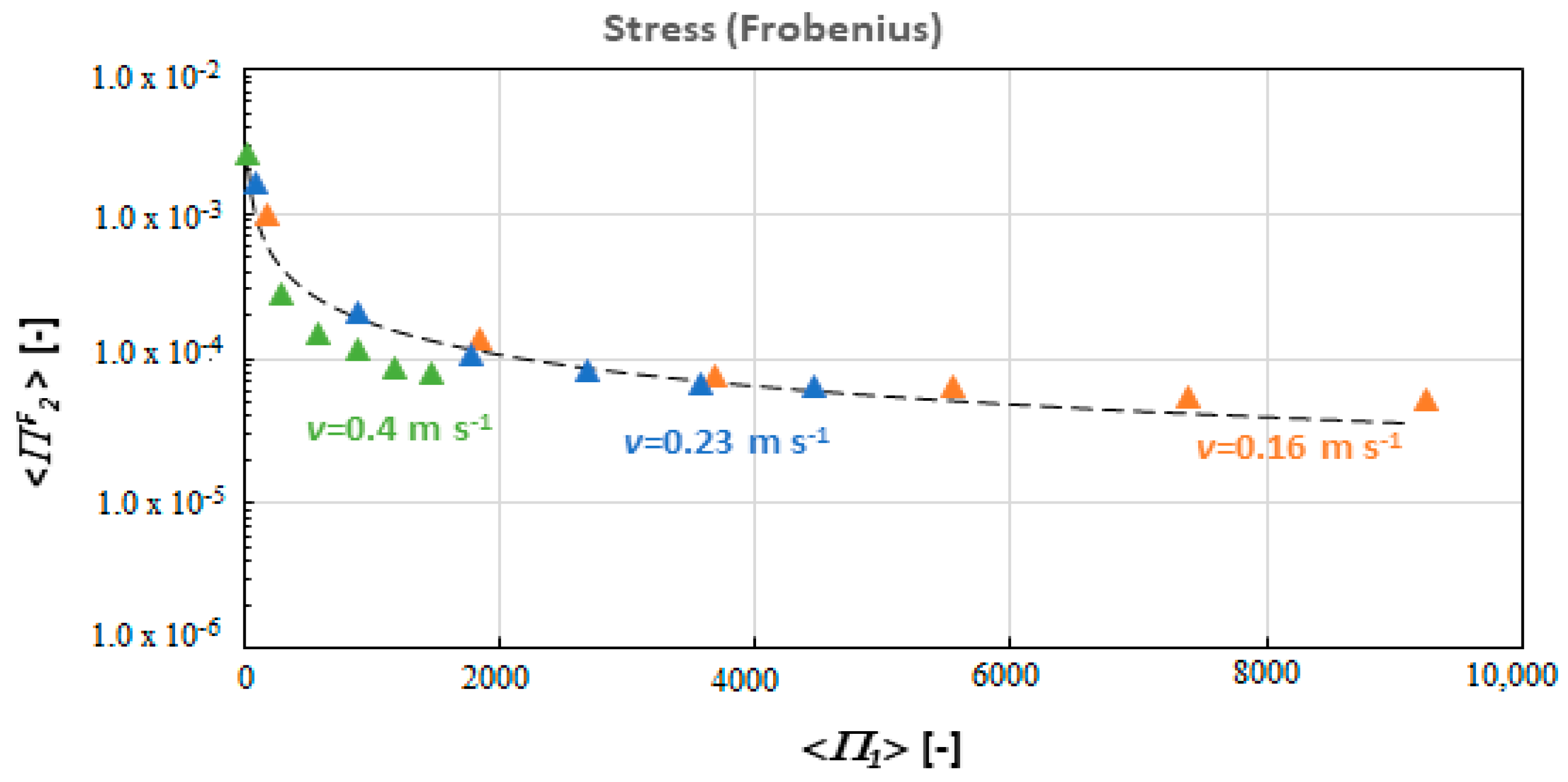
The result is first presented in Figure 4 and shows how the stress varies with k and v . This is then sorted in dimensionless form and presented in Figure 5 and Figure 6, which shows the average stress <ΠF2>, and <ΠV2> versus <Π1> in dimensionless form. If we use dimensionless numbers the three curves of Figure 4 collapse in only one curve (Figure 5 and Figure 6).
The plot confirms that the stress can be effectively sorted out with two dimensionless numbers based on the Buckingham π theorem. The three curves of Figure 4 can be fit by the same function as indicated in Equation (13). This function can be approximated by the following correlation (dotted line in)
< Π 2 F > = 0.026 Π 1 0.723 .
The same approach can be used for the von Mises stress which also has a correlation
< Π 2 V > = 0.058 Π 1 0.6737 .
Numerically, we identified that the dimensionless numbers computed can be used as the fundamental group of the system in which the stress can be express in terms of Π1 and Π2.
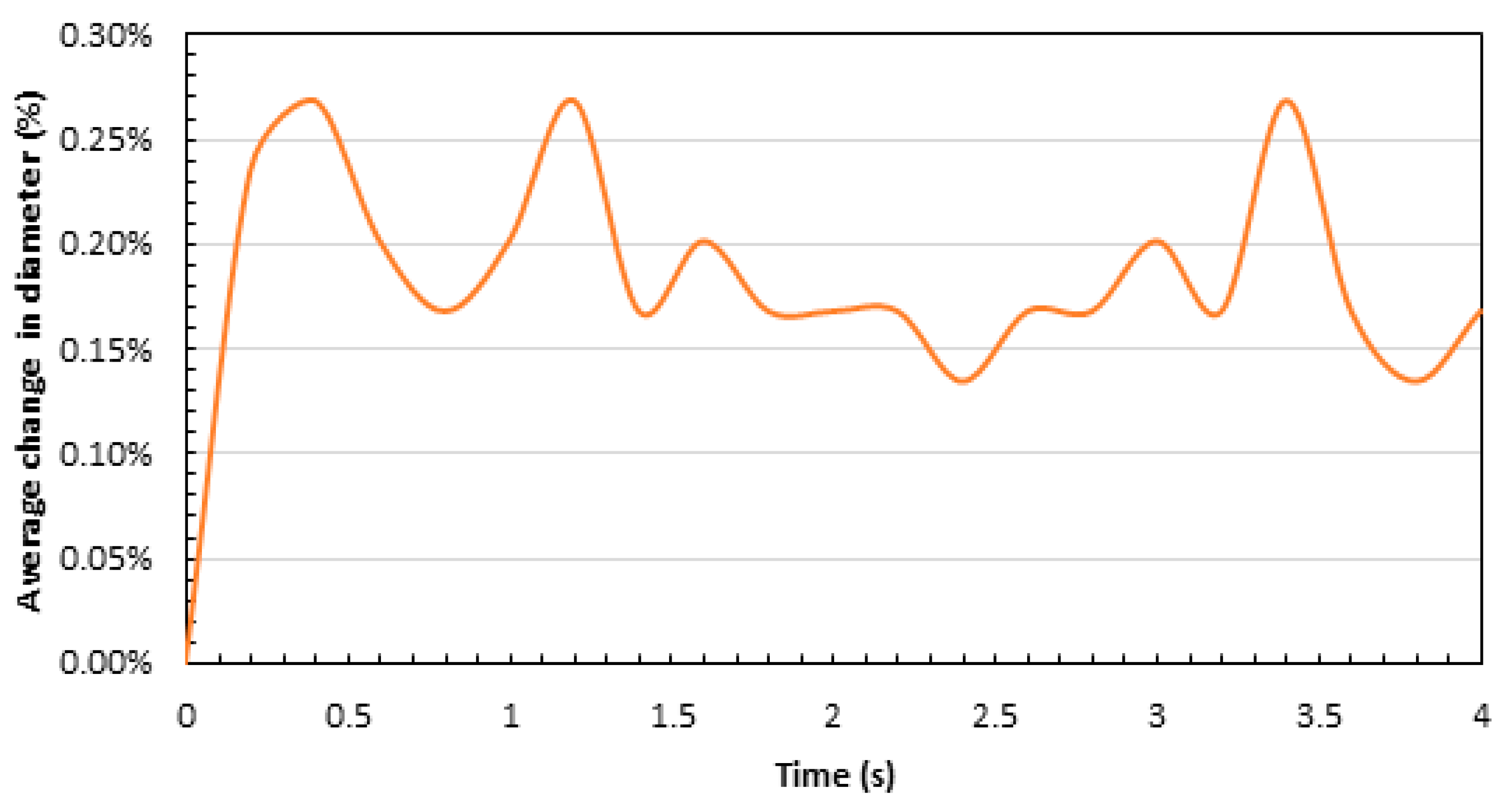
Due to the pulsatile flow, the stent contracts and expands during the simulation. This causes the diameter of the stent to change with the flow. Figure 7 shows that the percentage change in the stent’s diameter is fluctuating. This is because the arterial blood flow, which contributed to the stent deformation, is pulsatile in nature [54,55], therefore, it is expected to have a nonlinear change in the diameter. Note that the deformation is not only a function of the pressure forces from the liquid (blood) but also the elastic forces from the solid (stent). For that reason, several oscillation modes occur at the same time and the diameter change is not a simple repetition of the pulsatile flow.
Another likely incidence of vascular wall injury associated with stent expansion which can be quantified using the model is the so-called dogboning (DB) effect/ratio. This phenomenon occurs when the stent expands at the ends, resulting in increased stress and injuries at the arterial wall [53]. This occurs when the diameter expands at both ends of the stent and contracts at the centre. The dogboning ratio is defined as,
D B = D m a x , e n d D m i n , c e n t r a l D m a x , e n d × 100 %
where D m a x , e n d is the maximum stent diameter at the end (distal and proximal), and D m i n , c e n t r a l is the minimum stent diameter at the centre. Our model is capable of analysing the dogboning ratio which could be used to assess and reduce the potential risk of vascular wall injury, and therefore, in this study, DB was calculated to be 4.4%. This is less than the 6.3% reported by [25] for PS-shaped stent.

5. Conclusions

In this paper, a Discrete Multiphysics model is used to simulate a coronary stent accounting for both its hemodynamics and mechanical stress. The model is three-dimensional and includes both the fluid (blood) and the solid structures (arterial wall and stent) and it is used to study the link between the flow dynamics and the mechanical deformation of the stent. The mechanical stress is computed using dimensionless numbers and a relationship between elastic forces and pressure forces was established. The results show that the blood flow contributes significantly to the stent deformation and the stiffness of the stent material affected the rate of deformation. Nonuniform stress distributions are observed. In particular, high stresses are observed at the nodes of the stent.
Given a specific Π 1 and from the corresponding Π 2 V , the maximum stress can be obtained. However, a fracture is not directly accounted for. This will depend on the pressure (stress) and type of material used for the stent as reported by [19]. Different materials have different yield stress (above which the stent fracture occurs). Our model can be used for all types of material by comparing the maximal stress in the structure against the material yield stress. Using the correlation in Equation (21), maximum Π 2 V . can be found when a specific stent material’s property (Young modulus) is known. That means, from the value of Π 1 , we will be able to predict the Von Mises stress from Π 2 V (which can be compared against the yield stress) as well as the flow velocity. For clinical purposes, one just needs to know the material and the blood flow velocity in the diseased artery to be able to predict whether the stent is at risk of fracture or not. Therefore, the model can be used to predict the deformation of the stent once in place and the conditions that can potentially cause its failure.

Author Contributions

Conceptualization, M.A., A.M.M. and A.A.; simulation and visualization, A.M.M.; numerical calculations, A.M.M., M.A. and A.A.; interpretation and analysis of results, A.M.M. and A.A.; writing—original draft preparation, A.M.M.; supervision, A.A. and M.A.; writing—review and editing, A.A., A.M.M. and M.A.; input script, M.A. and A.M.M. All authors have read and agreed to the published version of the manuscript.

Funding

This research received no external funding.

Institutional Review Board Statement

Not applicable.

Informed Consent Statement

Not applicable.

Acknowledgments

The Nigerian Petroleum Technology Development Fund (PTDF) is acknowledged for the provision of a scholarship to Adamu Musa Mohammed.

Conflicts of Interest

The authors declare no conflict of interest.

References

  1. Brown, J.C.; Gerhardt, T.E.; Kwon, E. Risk Factors for Coronary Artery Disease. In StatPearls; StatPearls Publishing: Treasure Island, FL, USA, 2021. [Google Scholar]
  2. Kolodgie, F.D.; Nakazawa, G.; Sangiorgi, G.; Ladich, E.; Burke, A.P.; Virmani, R. Pathology of Atherosclerosis and Stenting. Neuroimaging Clin. N. Am. 2007, 17, 285–301. [Google Scholar] [CrossRef] [PubMed] [Green Version]
  3. Evju, Ø.; Mardal, K.-A. On the Assumption of Laminar Flow in Physiological Flows: Cerebral Aneurysms as an Illustrative Example. In Modeling the Heart and the Circulatory System; Quarteroni, A., Ed.; MS&A.; Springer International Publishing: Cham, Germany, 2015; Volume 14, pp. 177–195. ISBN 978-3-319-05229-8. [Google Scholar]
  4. Otsuka, F.; Yasuda, S.; Noguchi, T.; Ishibashi-Ueda, H. Pathology of Coronary Atherosclerosis and Thrombosis. Cardiovasc. Diagn. Ther. 2016, 6, 396–408. [Google Scholar] [CrossRef] [Green Version]
  5. Griffith, M.D.; Leweke, T.; Thompson, M.C.; Hourigan, K. Effect of Small Asymmetries on Axisymmetric Stenotic Flow. J. Fluid Mech. 2013, 721, R1. [Google Scholar] [CrossRef] [Green Version]
  6. Jain, K. Transition to Turbulence in an Oscillatory Flow through Stenosis. Biomech. Model. Mechanobiol. 2020, 19, 113–131. [Google Scholar] [CrossRef] [PubMed]
  7. Ahmed, S.A.; Giddens, D.P. Pulsatile Poststenotic Flow Studies with Laser Doppler Anemometry. J. Biomech. 1984, 17, 695–705. [Google Scholar] [CrossRef]
  8. Di Venuta, I.; Boghi, A.; Gori, F. Three-Dimensional Numerical Simulation of a Failed Coronary Stent Implant at Different Degrees of Residual Stenosis. Part I: Fluid Dynamics and Shear Stress on the Vascular Wall. Numer. Heat Transf. Part A Appl. 2017, 71, 638–652. [Google Scholar] [CrossRef]
  9. Pant, S.; Bressloff, N.W.; Limbert, G. Geometry Parameterization and Multidisciplinary Constrained Optimization of Coronary Stents. Biomech. Model. Mechanobiol. 2012, 11, 61–82. [Google Scholar] [CrossRef]
  10. Hsiao, H.-M.; Lee, K.-H.; Liao, Y.-C.; Cheng, Y.-C. Hemodynamic Simulation of Intra-Stent Blood Flow. Procedia Eng. 2012, 36, 128–136. [Google Scholar] [CrossRef] [Green Version]
  11. Wei, L.; Chen, Q.; Li, Z. Influences of Plaque Eccentricity and Composition on the Stent–Plaque–Artery Interaction during Stent Implantation. Biomech. Model. Mechanobiol. 2019, 18, 45–56. [Google Scholar] [CrossRef]
  12. Colombo, A.; Stankovic, G.; Moses, J.W. Selection of Coronary Stents. J. Am. Coll. Cardiol. 2002, 40, 1021–1033. [Google Scholar] [CrossRef] [Green Version]
  13. Balossino, R.; Gervaso, F.; Migliavacca, F.; Dubini, G. Effects of Different Stent Designs on Local Hemodynamics in Stented Arteries. J. Biomech. 2008, 41, 1053–1061. [Google Scholar] [CrossRef]
  14. Duraiswamy, N.; Jayachandran, B.; Byrne, J.; Moore, J.E.; Schoephoerster, R.T. Spatial Distribution of Platelet Deposition in Stented Arterial Models under Physiologic Flow. Ann. Biomed. Eng. 2005, 33, 1767–1777. [Google Scholar] [CrossRef] [PubMed]
  15. Pant, S.; Bressloff, N.W.; Forrester, A.I.J.; Curzen, N. The Influence of Strut-Connectors in Stented Vessels: A Comparison of Pulsatile Flow Through Five Coronary Stents. Ann. Biomed. Eng. 2010, 38, 1893–1907. [Google Scholar] [CrossRef] [PubMed]
  16. Finet, G.; Rioufol, G. Coronary Stent Longitudinal Deformation by Compression: Is This a New Global Stent Failure, a Specific Failure of a Particular Stent Design or Simply an Angiographic Detection of an Exceptional PCI Complication? EuroIntervention 2012, 8, 177–181. [Google Scholar] [CrossRef] [PubMed]
  17. Choudhury, T.R.; Al-Saigh, S.; Burley, S.; Li, L.; Shakhshir, N.; Mirhosseini, N.; Wang, T.; Arnous, S.; Khan, M.A.; Mamas, M.A.; et al. Longitudinal Deformation Bench Testing Using a Coronary Artery Model: A New Standard? Open Heart 2017, 4, e000537. [Google Scholar] [CrossRef] [PubMed]
  18. Ding, H.; Zhang, Y.; Liu, Y.; Shi, C.; Nie, Z.; Liu, H.; Gu, Y. Analysis of Vascular Mechanical Characteristics after Coronary Degradable Stent Implantation. BioMed Res. Int. 2019, 2019, 8265374. [Google Scholar] [CrossRef]
  19. Chinikar, M.; Sadeghipour, P. Coronary Stent Fracture: A Recently Appreciated Phenomenon with Clinical Relevance. Curr. Cardiol. Rev. 2014, 10, 349–354. [Google Scholar] [CrossRef] [PubMed] [Green Version]
  20. Alqahtani, A.; Suwaidi, J.; Mohsen, M. Stent Fracture: How Frequently Is It Recognized? Heart Views 2013, 14, 72. [Google Scholar] [CrossRef] [PubMed]
  21. Faik, I.; Mongrain, R.; Leask, R.L.; Rodes-Cabau, J.; Larose, E.; Bertrand, O. Time-Dependent 3D Simulations of the Hemodynamics in a Stented Coronary Artery. Biomed. Mater. 2007, 2, S28–S37. [Google Scholar] [CrossRef]
  22. Caiazzo, A.; Evans, D.; Falcone, J.-L.; Hegewald, J.; Lorenz, E.; Stahl, B.; Wang, D.; Bernsdorf, J.; Chopard, B.; Gunn, J.; et al. A Complex Automata Approach for In-Stent Restenosis: Two-Dimensional Multiscale Modelling and Simulations. J. Comput. Sci. 2011, 2, 9–17. [Google Scholar] [CrossRef]
  23. Beier, S.; Ormiston, J.; Webster, M.; Cater, J.; Norris, S.; Medrano-Gracia, P.; Young, A.; Cowan, B. Hemodynamics in Idealized Stented Coronary Arteries: Important Stent Design Considerations. Ann. Biomed. Eng. 2016, 44, 315–329. [Google Scholar] [CrossRef] [PubMed] [Green Version]
  24. Xu, J.; Yang, J.; Huang, N.; Uhl, C.; Zhou, Y.; Liu, Y. Mechanical Response of Cardiovascular Stents under Vascular Dynamic Bending. Biomed. Eng. Online 2016, 15, 21. [Google Scholar] [CrossRef] [PubMed] [Green Version]
  25. Wei, L.; Leo, H.L.; Chen, Q.; Li, Z. Structural and Hemodynamic Analyses of Different Stent Structures in Curved and Stenotic Coronary Artery. Front. Bioeng. Biotechnol. 2019, 7, 366. [Google Scholar] [CrossRef] [PubMed] [Green Version]
  26. Alexiadis, A. A Smoothed Particle Hydrodynamics and Coarse-Grained Molecular Dynamics Hybrid Technique for Modelling Elastic Particles and Breakable Capsules under Various Flow Conditions: SPH-CGMD HYBRID. Int. J. Numer. Meth. Eng. 2014, 100, 713–719. [Google Scholar] [CrossRef]
  27. Schütt, M.; Stamatopoulos, K.; Simmons, M.J.H.; Batchelor, H.K.; Alexiadis, A. Modelling and Simulation of the Hydrodynamics and Mixing Profiles in the Human Proximal Colon Using Discrete Multiphysics. Comput. Biol. Med. 2020, 121, 103819. [Google Scholar] [CrossRef]
  28. Ariane, M.; Kassinos, S.; Velaga, S.; Alexiadis, A. Discrete Multi-Physics Simulations of Diffusive and Convective Mass Transfer in Boundary Layers Containing Motile Cilia in Lungs. Comput. Biol. Med. 2018, 95, 34–42. [Google Scholar] [CrossRef] [PubMed]
  29. Mohammed, A.M.; Ariane, M.; Alexiadis, A. Using Discrete Multiphysics Modelling to Assess the Effect of Calcification on Hemodynamic and Mechanical Deformation of Aortic Valve. ChemEngineering 2020, 4, 48. [Google Scholar] [CrossRef]
  30. Ariane, M.; Wen, W.; Vigolo, D.; Brill, A.; Nash, F.G.B.; Barigou, M.; Alexiadis, A. Modelling and Simulation of Flow and Agglomeration in Deep Veins Valves Using Discrete Multi Physics. Comput. Biol. Med. 2017, 89, 96–103. [Google Scholar] [CrossRef]
  31. Ariane, M.; Vigolo, D.; Brill, A.; Nash, F.G.B.; Barigou, M.; Alexiadis, A. Using Discrete Multi-Physics for Studying the Dynamics of Emboli in Flexible Venous Valves. Comput. Fluids 2018, 166, 57–63. [Google Scholar] [CrossRef]
  32. Albano, A.; Alexiadis, A. A Smoothed Particle Hydrodynamics Study of the Collapse for a Cylindrical Cavity. PLoS ONE 2020, 15, e0239830. [Google Scholar] [CrossRef]
  33. Albano, A.; Alexiadis, A. Non-Symmetrical Collapse of an Empty Cylindrical Cavity Studied with Smoothed Particle Hydrodynamics. Appl. Sci. 2021, 11, 3500. [Google Scholar] [CrossRef]
  34. Liu, W.; Wu, C.-Y. Modelling Complex Particle–Fluid Flow with a Discrete Element Method Coupled with Lattice Boltzmann Methods (DEM-LBM). ChemEngineering 2020, 4, 55. [Google Scholar] [CrossRef]
  35. Ng, K.C.; Alexiadis, A.; Chen, H.; Sheu, T.W.H. A Coupled Smoothed Particle Hydrodynamics-Volume Compensated Particle Method (SPH-VCPM) for Fluid Structure Interaction (FSI) Modelling. Ocean Eng. 2020, 218, 107923. [Google Scholar] [CrossRef]
  36. Sahputra, I.H.; Alexiadis, A.; Adams, M.J. A Coarse Grained Model for Viscoelastic Solids in Discrete Multiphysics Simulations. ChemEngineering 2020, 4, 30. [Google Scholar] [CrossRef]
  37. Ruiz-Riancho, I.N.; Alexiadis, A.; Zhang, Z.; Garcia Hernandez, A. A Discrete Multi-Physics Model to Simulate Fluid Structure Interaction and Breakage of Capsules Filled with Liquid under Coaxial Load. Processes 2021, 9, 354. [Google Scholar] [CrossRef]
  38. Sanfilippo, D.; Ghiassi, B.; Alexiadis, A.; Hernandez, A.G. Combined Peridynamics and Discrete Multiphysics to Study the Effects of Air Voids and Freeze-Thaw on the Mechanical Properties of Asphalt. Materials 2021, 14, 1579. [Google Scholar] [CrossRef] [PubMed]
  39. Alexiadis, A. Deep Multiphysics and Particle–Neuron Duality: A Computational Framework Coupling (Discrete) Multiphysics and Deep Learning. Appl. Sci. 2019, 9, 5369. [Google Scholar] [CrossRef] [Green Version]
  40. Alexiadis, A.; Simmons, M.J.H.; Stamatopoulos, K.; Batchelor, H.K.; Moulitsas, I. The Duality between Particle Methods and Artificial Neural Networks. Sci. Rep. 2020, 10, 16247. [Google Scholar] [CrossRef]
  41. Liu, G.R.; Liu, M.B. Smoothed Particle Hydrodynamics: A Meshfree Particle Method; World Scientific: Singapore, 2003; ISBN 978-981-238-456-0. [Google Scholar]
  42. Kot, M.; Nagahashi, H.; Szymczak, P. Elastic Moduli of Simple Mass Spring Models. Vis. Comput. 2015, 31, 1339–1350. [Google Scholar] [CrossRef]
  43. Kot, M. Mass Spring Models of Amorphous Solids. ChemEngineering 2021, 5, 3. [Google Scholar] [CrossRef]
  44. Monaghan, J.J. Smoothed Particle Hydrodynamics. Annu. Rev. Astron. Astrophys. 1992, 30, 543–574. [Google Scholar] [CrossRef]
  45. Morris, J.P.; Fox, P.J.; Zhu, Y. Modeling Low Reynolds Number Incompressible Flows Using SPH. J. Comput. Phys. 1997, 136, 214–226. [Google Scholar] [CrossRef]
  46. Pazdniakou, A.; Adler, P.M. Lattice Spring Models. Transp. Porous Med. 2012, 93, 243–262. [Google Scholar] [CrossRef]
  47. Wall, J.G.; Podbielska, H.; Wawrzyńska, M. (Eds.) Functionalized Cardiovascular Stents; Woodhead Publishing Series in Biomaterials; Elsevier: Amsterdam, The Netherlands; Woodhead Publishing: Duxford, UK; Cambridge, MA, USA, 2018; ISBN 978-0-08-100496-8. [Google Scholar]
  48. Plimpton, S. Fast Parallel Algorithms for Short-Range Molecular Dynamics. J. Comput. Phys. 1995, 117, 1–19. [Google Scholar] [CrossRef] [Green Version]
  49. Ku, D.N. Blood Flow in Arteries. Annu. Rev. Fluid Mech. 1997, 29, 399–434. [Google Scholar] [CrossRef]
  50. Stukowski, A. Visualization and Analysis of Atomistic Simulation Data with OVITO–the Open Visualization Tool. Model. Simul. Mater. Sci. Eng. 2010, 18, 015012. [Google Scholar] [CrossRef]
  51. Alexiadis, A. The Discrete Multi-Hybrid System for the Simulation of Solid-Liquid Flows. PLoS ONE 2015, 10, e0124678. [Google Scholar] [CrossRef] [Green Version]
  52. Vrints, C.J.; Claeys, M.J.; Bosmans, J.; Conraads, V.; Snoeck, J.P. Effect of Stenting on Coronary Flow Velocity Reserve: Comparison of Coil and Tubular Stents. Heart 1999, 82, 465–470. [Google Scholar] [CrossRef] [PubMed]
  53. Wiesent, L.; Schultheiß, U.; Schmid, C.; Schratzenstaller, T.; Nonn, A. Experimentally Validated Simulation of Coronary Stents Considering Different Dogboning Ratios and Asymmetric Stent Positioning. PLoS ONE 2019, 14, e0224026. [Google Scholar] [CrossRef] [Green Version]
  54. Huo, Y.; Kassab, G.S. Pulsatile Blood Flow in the Entire Coronary Arterial Tree: Theory and Experiment. Am. J. Physiol. Heart Circ. Physiol. 2006, 291, H1074–H1087. [Google Scholar] [CrossRef]
  55. Cheung, Y. Systemic Circulation. In Paediatric Cardiology; Elsevier: Amsterdam, The Netherlands, 2010; pp. 91–116. ISBN 978-0-7020-3064-2. [Google Scholar]
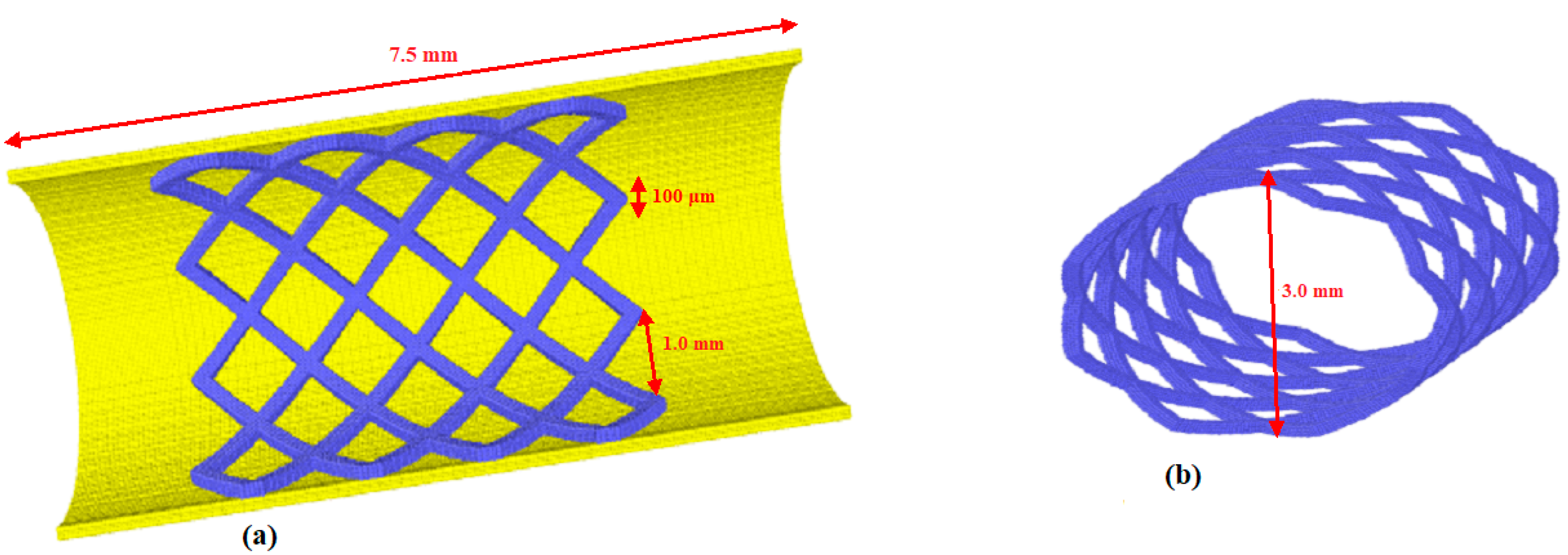
Figure 1. Illustration of the 3D stent geometry at (a) section view; and (b) front view showing complete stent.
Chemengineering 05 00060 g001
Figure 2. Velocity profile; (a) x-y view (steady state profile), (b) y-z view, and (c) parabolic profile at the beginning of the flow.
Chemengineering 05 00060 g002
Figure 3. Local ΠV2 at (a) Π1 = 296, and (b) Π1 = 1480.
Chemengineering 05 00060 g003
Figure 4. Stress (Frobenius norm of the stress tensor) with respect to k and v .
Chemengineering 05 00060 g004
Figure 5. Relationship between average stress <ΠF2> and <Π1>.
Chemengineering 05 00060 g005
Figure 6. Relationship between average stress <ΠV2> and <Π1>.
Chemengineering 05 00060 g006
Figure 7. Average diameter change with time.
Chemengineering 05 00060 g007
Table 1. Parameters used in the simulation.
SPH
Number of SPH fluid particles1,609,452
Mass of each particle (fluid)3.41 × 10⁻¹² kg
Length L7.5 × 10−3 m
Diameter D3.0 × 10−3 m
Particle spacing l3.33 × 10−5 m
Smoothing length h7.5 × 10−5 m
Local acceleration term g00.47138–1.25 m s−2
Fluid Density ρ1056 kg m−3
Viscosity μ0.0035 Pa∙s
Sound speed c04 m s−1
Alpha α0.1–0.25 [-]
Time step Δt1 × 10−7 s
LSM
Number of SPH stent particles46,336
Number of SPH wall particles207,016
Mass of each particle of the stent (Solid)3.41 × 10⁻¹² kg
Mass of each particle of the wall (Solid)6.0 × 10⁻¹² kg
Stent thickness d 1.0 × 10⁻⁴ m
Elastic constant k0.5−25 kg s−2
Publisher’s Note: MDPI stays neutral with regard to jurisdictional claims in published maps and institutional affiliations.