Article

An Assessment of Drag Models in Eulerian–Eulerian CFD Simulation of Gas–Solid Flow Hydrodynamics in Circulating Fluidized Bed Riser

School of Energy and Chemical Engineering; Ulsan National Institute of Science and Technology (UNIST); 50 UNIST-gil, Eonyang-eup, Ulju-gun, Ulsan 44919, Korea
*
Author to whom correspondence should be addressed.
ChemEngineering 2020, 4(2), 37; https://doi.org/10.3390/chemengineering4020037
Submission received: 29 April 2020 / Revised: 27 May 2020 / Accepted: 4 June 2020 / Published: 6 June 2020
(This article belongs to the Special Issue Computational Fluid Dynamics (CFD) of Chemical Processes)

Abstract

:
Accurate prediction of the hydrodynamic profile is important for circulating fluidized bed (CFB) reactor design and scale-up. Multiphase computational fluid dynamics (CFD) simulation with interphase momentum exchange is key to accurately predict the gas-solid profile along the height of the riser. The present work deals with the assessment of six different drag model capability to accurately predict the riser section axial solid holdup distribution in bench scale circulating fluidized bed. The difference between six drag model predictions were validated against the experiment data. Two-dimensional geometry, transient solver and Eulerian–Eulerian multiphase models were used. Six drag model simulation predictions were discussed with respect to axial and radial profile. The comparison between CFD simulation and experimental data shows that the Syamlal-O’Brien, Gidaspow, Wen-Yu and Huilin-Gidaspow drag models were successfully able to predict the riser upper section solid holdup distribution with better accuracy, however unable to predict the solid holdup transition region. On the other hand, the Gibilaro model and Helland drag model were successfully able to predict the bottom dense region, but the upper section solid holdup distribution was overpredicted. The CFD simulation comparison of different drag model has clearly shown the limitation of the drag model to accurately predict overall axial heterogeneity with accuracy.

1. Introduction

The gas–solid fluidized bed reactors are widely used in the petrochemical, power generation, environmental and metallurgical industries [1]. In the circulating fluidized bed (CFB) system, solid particles are separated from the fluid stream using cyclone and recycle to the bed. The solid particles fluid-like state provide excellent heat and mass transfer characteristic and circulation of solid offer operational flexibility [2,3]. The CFB riser section serves as the main reaction zone, in which strands of particles (clusters) influence the flow and the performance of reactor [4]. Over the years, considerable effort has been made to better design and operation of CFB reactor. In particular, focus to better understand the underlying gas–solid flow hydrodynamics in the riser section.
Over the year, computational fluid dynamics (CFD) domain has undergone significant development and regularly applied for investigating gas-solid multiphase flow phenomena. For example, direct numerical simulation (DNS), large eddy simulation (LES) and Reynolds-Averaged Navier-Stokes simulation (RANS) are three modelling methods at different computational scales to account the turbulence in multiphase flow. The accuracy of these numerical methods depends on the scheme. Several high order schemes were developed, such as essentially non-oscillatory (ENO) method [5,6], weighted ENO (WENO) method [7], discontinuous Galerkin (DG) method [8], radial basis function method [9] and gas-kinetic method [10,11]. However, for most industrial scale problem DNS and LES simulation were considered impractical for the general-purpose design tool [12]. RANS based CFD method has become a standard platform to simulate gas–solid multiphase flow in industrial scale fluidized bed reactor [13]. To model the gas–solid flow, the most commonly employed CFD simulation methods are the Eulerian–Eulerian two-fluid model (EE-TFM), [14,15,16] Eulerian–Lagrangian discrete element method (EL-DEM) [17,18], and hybrid multiphase particle-in-cell (MP-PIC) [19,20]. The principal difference among these approaches is on the treatment of the secondary solid phase. In EE-TFM approach kinetic theory of granular flow (KTGF) closure model were incorporated to simulate solid particle flow. EE-TFM model constitutive relationship contains solid phase stress, interphase momentum transfer and particle interactions [13,16,21]. Researchers have shown that the interphase drag force is the critical closure model to accurately predict the gas–solid flows [22,23]. Agrawal et al. [23] has shown that the solid phase stress contribution was insignificant, and it is crucial to accurately account for the solid particle clusters.
Researchers have proposed the drag model based on flow conditions. In the literature, drag models were classically arranged into two groups, i.e., structure-based drag models and conventional drag models. Among the conventional drag models, Wen-Yu [24], Gidaspow [25] and Syamlal-O’Brien [26] were widely incorporated, which were derived from dense packed bed experimental pressure drop data and terminal velocity deduce using single solid particle. The most widely used Gidaspow model correlation consist of Ergun [27] and Wen-Yu [24] equations. To accurately simulate the riser gas-solid multiphase flow, researchers incorporated drag coefficient to account for the particle cluster. Researchers have pointed out that the particles cluster settling velocity is about 20% to 100% higher than the single particles. Also recognized that the such drag reduction occurred in the low solid volume fraction region. Various drag models have been incorporated to simulate the gas–solid riser flow, as detail were provided in Appendix A. Among the works in the literature, Gidaspow and EMMS drag model has been widely used. Shah et al. [28] simulate fluid catalytic cracking (FCC) riser section using EMMS and the Gidaspow drag model for low and high solid circulation rate. They reported EMMS drag model successfully able to predict the riser axial heterogenous profile. However, unable to predict the solid volume fraction transition region. Vaishali et al. [29] perform CFD simulation for fast fluidization and dilute phase transport flow regime with Geldart B particles. They reported that the Wen-Yu drag model underpredicts the velocity profile and Syamlal-O’Brien drag model show better prediction. Wang et al. [30] investigate the models and model parameters variation on hydrodynamic prediction behavior for high solid circulation rate. Their drag model comparison study shows that the Syamlal-O’Brien, Gidaspow and Wen-Yu drag models predict the global profile similarly; however, on radial direction, the Syamlal-O’Brien drag model shows better accuracy. Similarly, Zhang et al. [31,32] compare EMMS and Gidaspow drag models, and it was reported that the EMMS drag model prediction is good in the axial and radial direction. Despite several studies, it is important to examine the influence of drag models for specific flow condition and material type. Hence, in the present work an assessment of the appropriate drag model selection for in-house CFB riser setup was carried out. Generated CFD simulation profile were plotted against experimentally obtain axial solid holdup data for detail assessment and validation purpose.
In the present work six drag models (Syamlal-O’Brien [26], Gidaspow [25], Wen-Yu [24], Huilin-Gidaspow [33], Gibilaro [34] and Helland [35]) were investigated. In order to keep the computational load at a reasonable level, simple 2D simulations were performed. A detailed discussion is presented to illustrate the inherent difference between different drag model prediction. Such a comparison study is expected to provide clear guidelines on selection of appropriate drag model selection for gas–solid riser flow.

2. Simulation System

In the present work, air used as fluidizing gas and 4 kg of silica sand solid particles were loaded into CFB reactor. CFD simulation was conducted at the same flow conditions as the work described in previous paper [16]. CFB riser simplified two-dimensional computational domain with the height of 3 m and a diameter of 0.025 m, shown in Figure 1a. To ensure symmetry flow the gas velocity was specified at the bottom, the solid phase were introduced from two sides and straight outlet, shown in Figure 1b. The gas and solid particle properties, system geometry and flow condition were summarized in Table 1. Our previous study investigated the optimum number of computational cells [16]. Therefore, 19,500 (13 × 1500) cells with a size of a 15-particle diameter were used to simulate the gas–solid flow in the riser.

3. CFD Model

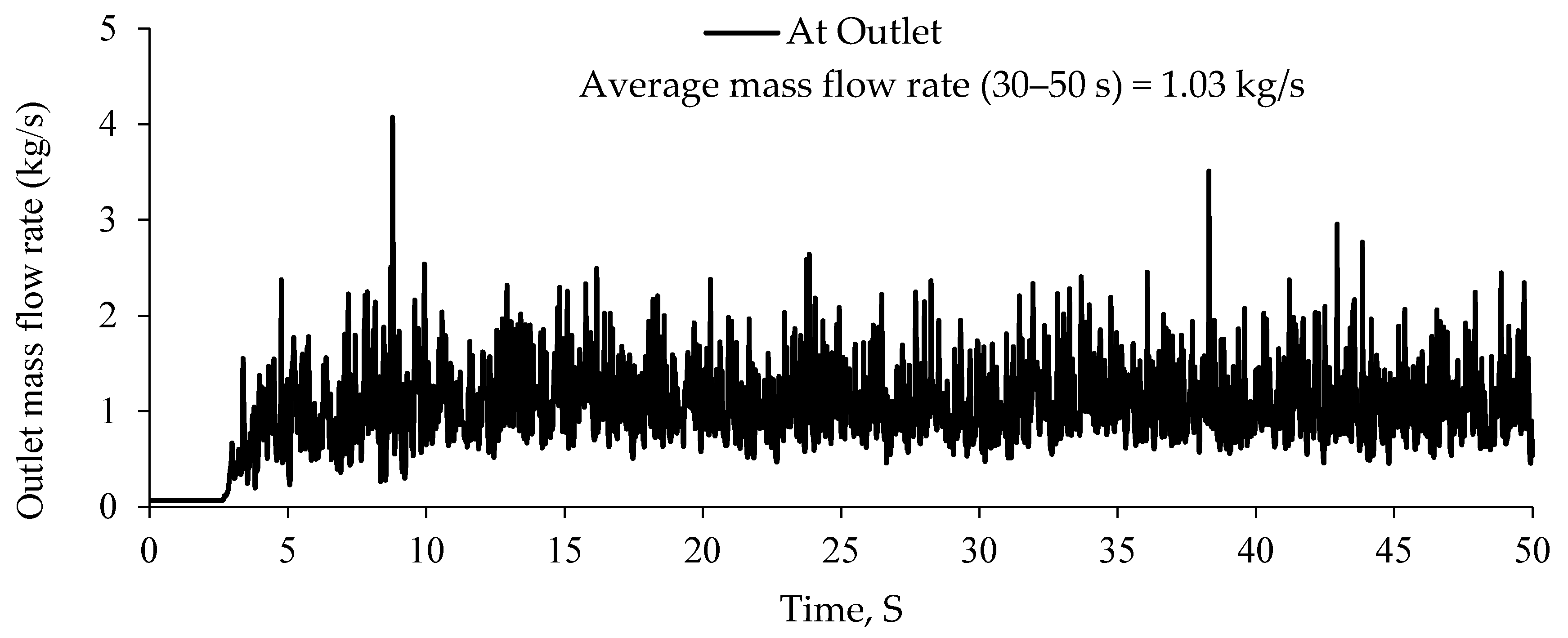
Gas–solid CFD simulation was developed based on Eulerian–Eulerian two-fluid model (EE-TFM) [16] in ANSYS Fluent 2020R1 software. EE-TFM simulation equations are presented in Appendix B, and a detailed description of governing equations can be found elsewhere [14,15]. To correctly capture the riser gas–solid multiphase flow phenomena, granular temperature equation in partial-differential form was used to resemble the solid phase properties [36]. The standard k-ε turbulence model was selected to account the gas phase turbulence. Under Johnson and Jackson [16], the particle–wall interaction parameter, specularity coefficient (φ) and particle–wall restitution coefficient (ew) value were set at 0.0001 and 0.9, respectively. Elasticity between solid phase, defined as the particle–particle restitution coefficient (ess), was set to 0.9. The transient CFD calculations were performed, where time step of 0.0005 s was selected to capture riser gas-solid flow behavior. Coupling between the velocity and pressure was employed by a phase-coupled SIMPLE scheme, and other important simulation parameters are given in Table 2. Before post-processing, the riser outlet mass flow rate was monitored as a function of time to confirm the pseudo-steady state profile, as shown in Figure 2. All the transient simulations were run for 30 s and reported results were employed by time-averaging the simulation results over last 20 s. The interphase momentum exchange between the gas and solid phases was provided through the drag coefficient. Six different drag models investigated in the present work; drag correlations are given in Table 3.

4. Result and Discussion

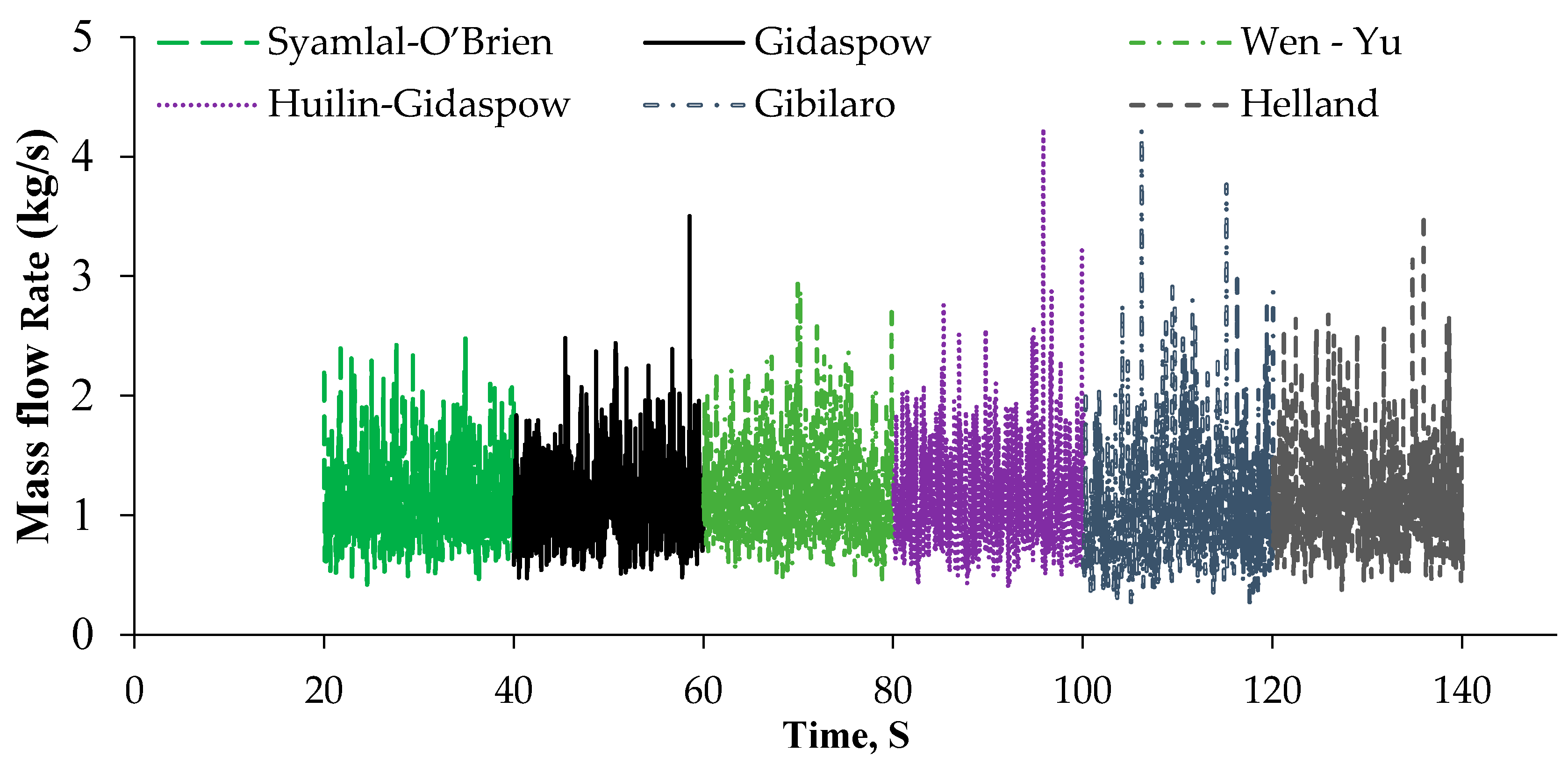
Before comparing drag model simulation results against experimental data, riser outlet mass flow rate transient profile as function of time for the six different drag models were shown in Figure 3. Riser outlet mass flow rate data for all investigated drag models were plotted for about 20 s in which all simulations have achieved a pseudo-steady state. It is interesting to note that the outlet mass flow rate profile for the Syamlal-O’Brien [26], Gidaspow [25], Wen–Yu [24] and Huilin-Gidaspow [33] drag models were fluctuating around the average mass flow rate of 1.04 kg/s compared to the Gibilaro [34] and Helland [35] drag models. Such comparison shows a distinct mass flow rate profile for different drag models; it can also be helpful to interpret model prediction behavior by analyzing the outlet mass flow rate.
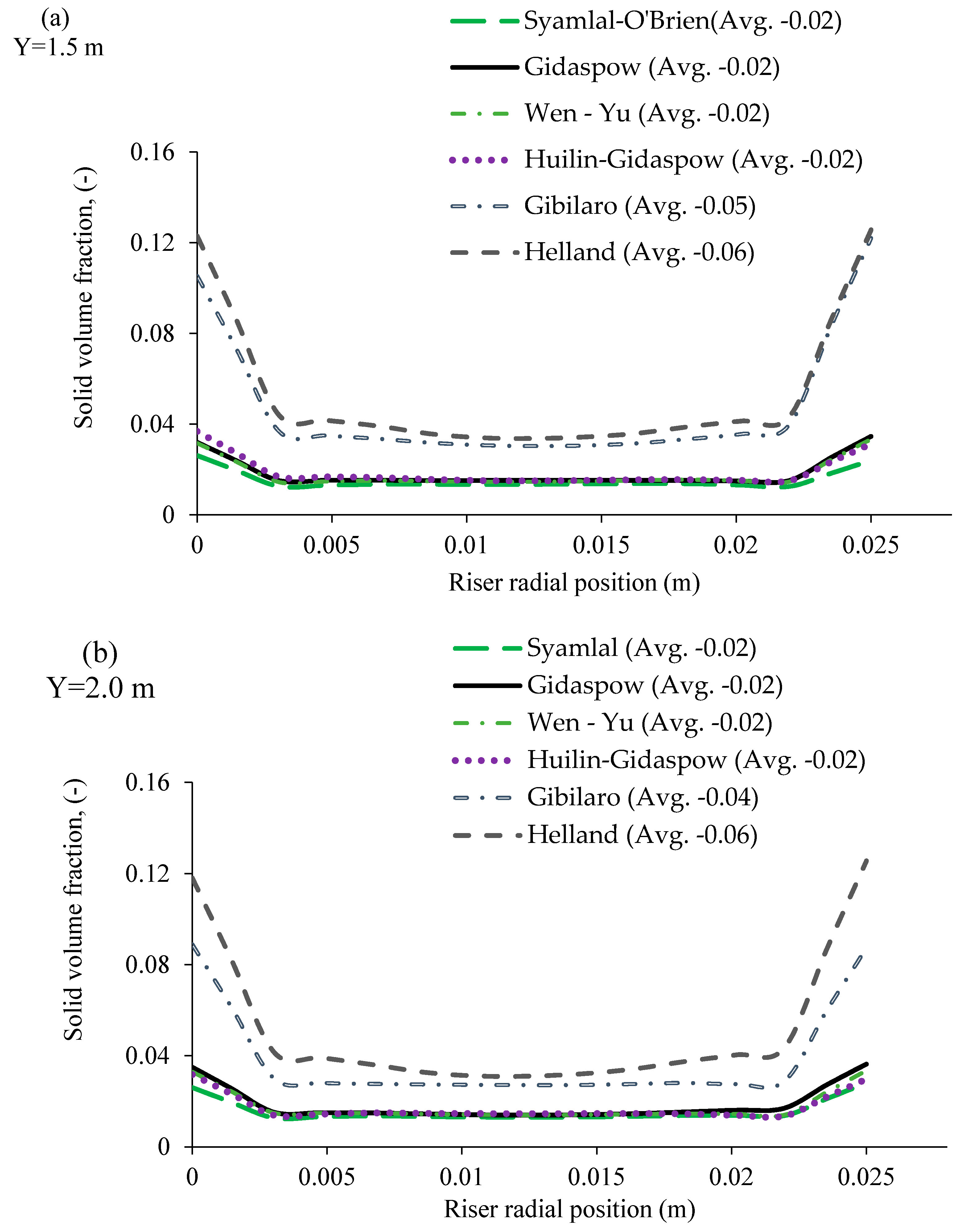
Figure 4 shows the time-averaged solid volume fraction distribution for Syamlal-O’Brien, Gidaspow, Wen and Yu, Huilin-Gidaspow, Gibilaro and Helland drag models at a height of 1.5 and 2.0 m. For the Gibilaro and Helland drag model, the solid volume fraction transition from wall to core is sharp, whereas flow structure prediction with other drag model shows relatively uniform flow structure. In terms of quantitative comparison, the average mean solid volume fraction is indicated in the corresponding drag model name. The quantitative comparison reveals that the solid volume fractions are higher for Gibilaro and Helland than other drag models. When we compare drag model predictions for two different height, i.e., for 1.5 and 2.0 m, it observed that the solid volume fraction profile and average mean velocity value are approximately similar.
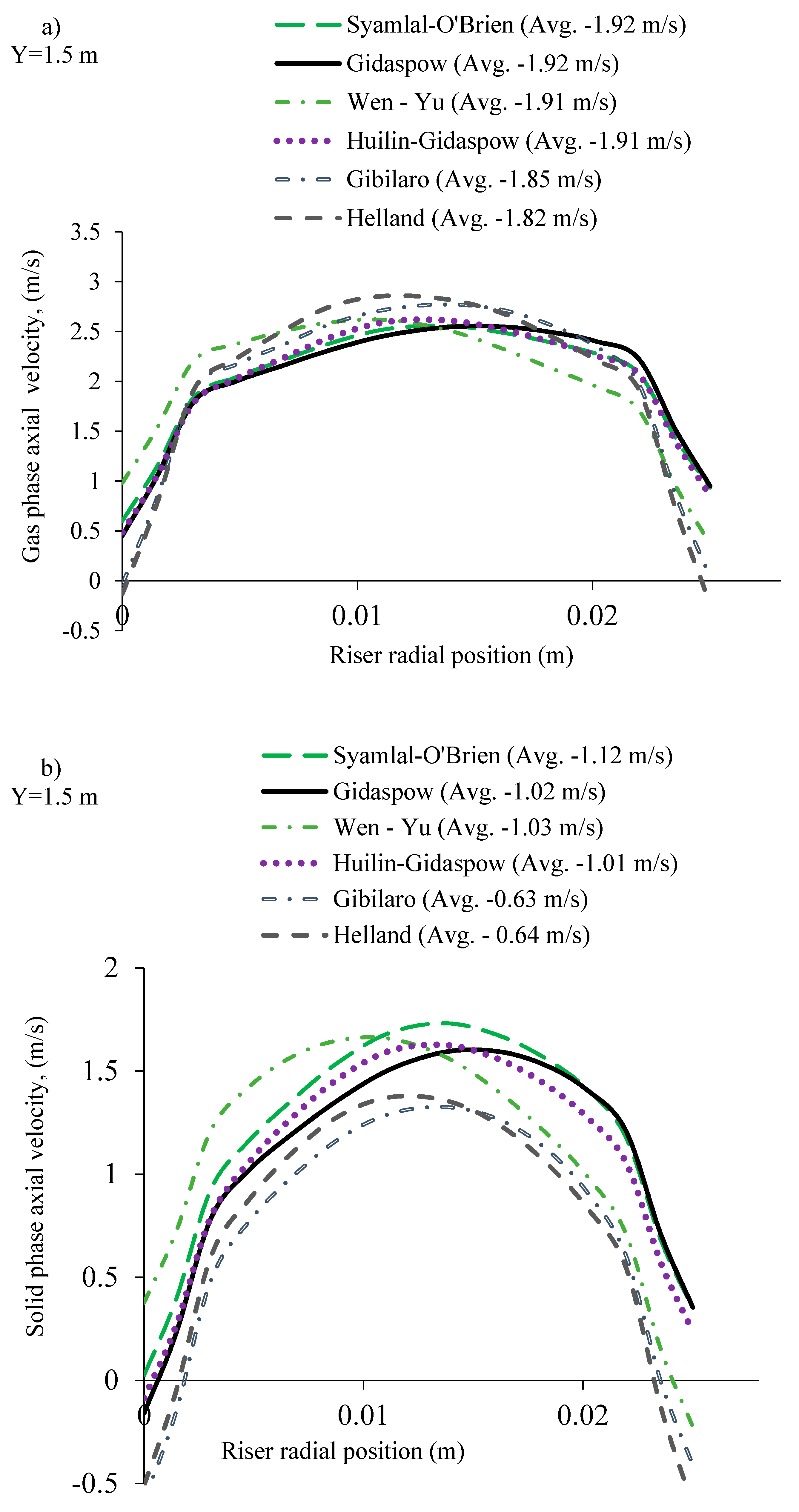
The influence of drag model is further illustrated by the time-averaged gas and solid phase axial velocity profile at a riser height of 1.5 m. The predicted time-averaged mean velocity for six different drag models were shown in Figure 5. It can be seen that the riser characteristic core–annulus flow structure observed in all cases. The highest gas velocity observed in the center and lowest value near the wall. Comparison clearly shows that the gas and the solid velocity magnitude and flow pattern variation for different drag models. For quantitative comparison, mean velocity value along the radial position were averaged and indicated in corresponding drag models. According to the value, gas phase axial average velocity is lowered by 4% from Syamlal-O’Brien, Gidaspow, Wen-Yu and Huilin-Gidaspow drag model to Gibilaro model and Helland drag model, whereas solid phase axial average velocity is lowered 39%. This over prediction of drag coefficient value results in higher mean solid velocity profile.
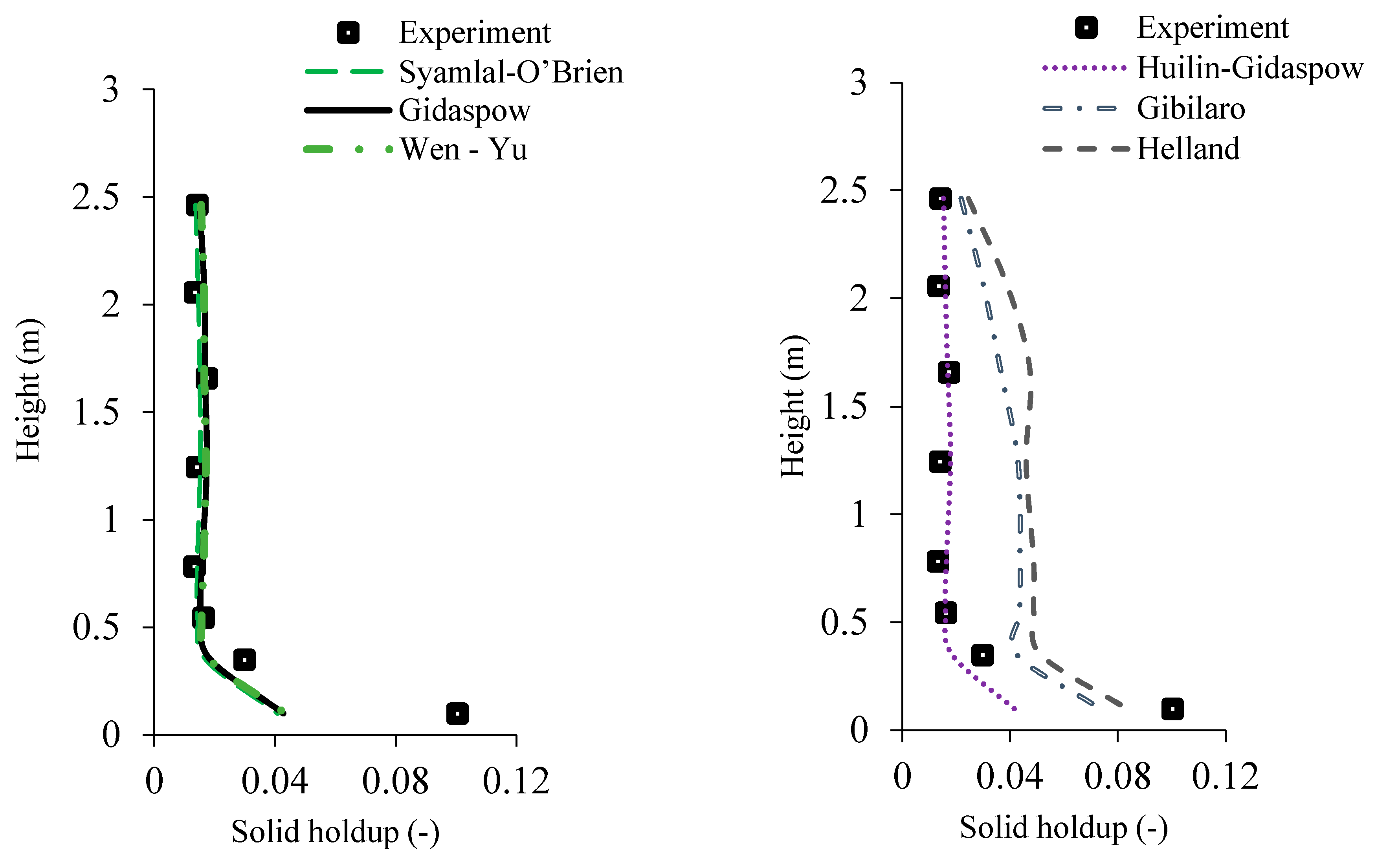
Figure 6 shows the time-averaged axial solid holdup profiles from different drag models. CFB riser experimental data exhibited L-shaped solid holdup profile. Syamlal-O’Brien, Gidaspow, Wen-Yu and Huilin-Gidaspow drag model predicts similar axial solid holdup and able to reproduce typical L-shaped flow characteristics profile. Compare to other drag models, Gibilaro and the Helland drag model predicts higher solid holdup all along the height of riser. Interestingly solid holdup values being gradually declined from around 1.75 m to the outlet of the riser. The solid holdup prediction from the Syamlal-O’Brien, Gidaspow, Wen-Yu and Huilin-Gidaspow drag models were closer to the experimental values in the mid-section and upper section of the riser, whereas the Gibilaro and Helland drag model agreed reasonably well with the experimental data below 0.5 m. The overall performance of six different drag models was further assessed using root mean square error (RMSE) method as follows.
R M S E = 1 n i = 1 n ( ε s e x p e r i m e n t ε s C F D ) 2
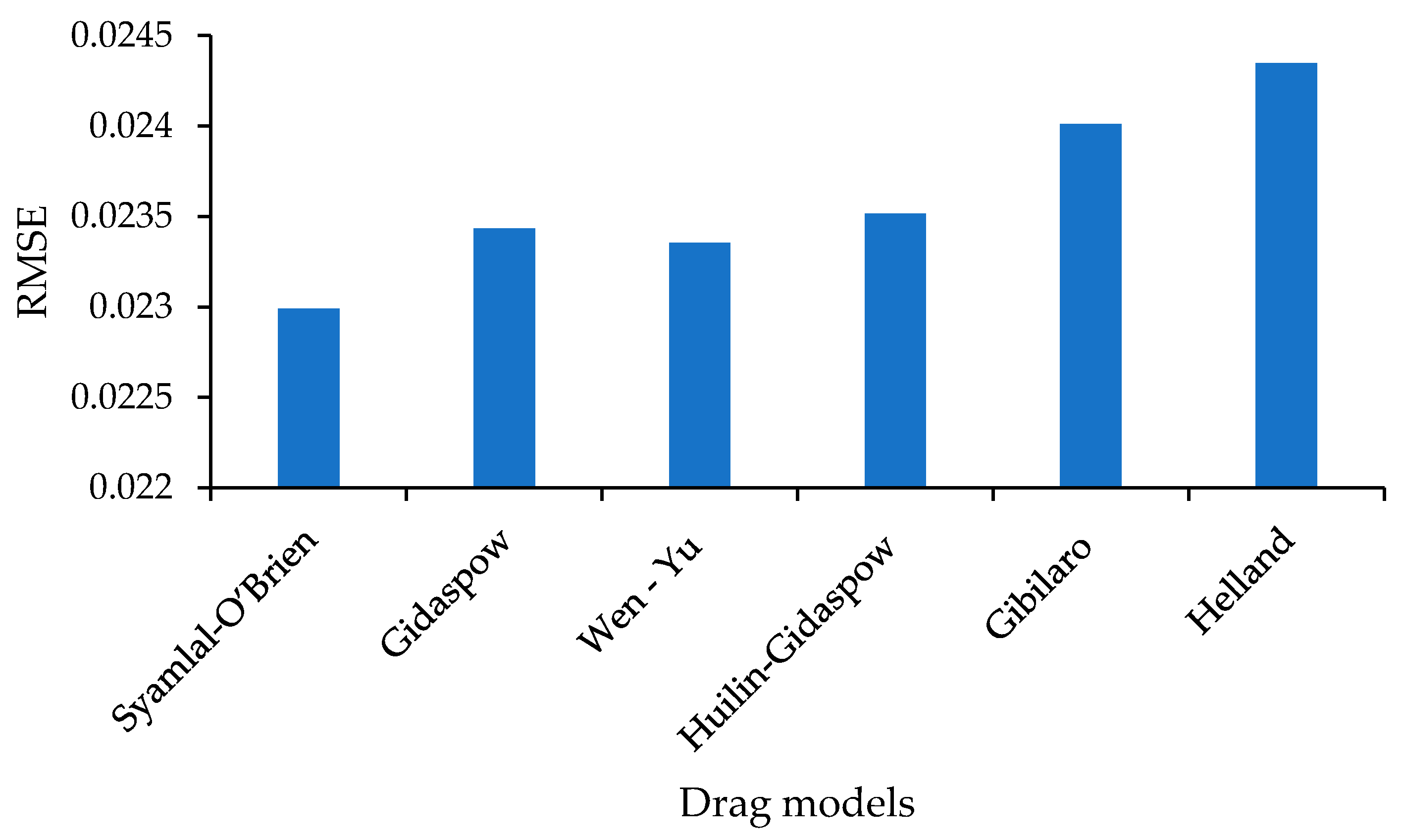
where ε s e x p e r i m e n t experimental solid holdup value and ε s C F D solid holdup predicted from six different drag models. Small RMSE indicates a closer model prediction to the experimental data. Figure 7 displays the RMSE for CFD simulation prediction with respect to six different drag models. RMSE values were calculated from different height of the riser and averaged. CFD simulation results with the Helland drag model shows highest RMSE value compared to that Syamlal-O’Brien drag model has the lowest value. This comparison demonstrates that the Syamlal-O’Brien, Gidaspow and Wen-Yu drag models predict closer to the experimental data. Similarly, we found Gibilaro drag models RMSE value is higher than other drag model. Comparison between experiment and simulated axial solid holdup value using RMSE data demonstrates that the simulation prediction all along the height of riser reflected on RMSE value. Among all test drag models, none of the drag model successfully able to fully capture the upper dilute and bottom dense region. Therefore, in next part of this study is to formulate drag reduction correlation for given gas velocity, solid circulation rate and material type using three-dimensional (3D) CFD simulation.

5. Conclusions

In this work, we investigate the limitation of six different drag models to predict the solid holdup profile in the riser section of circulating fluidized bed (CFB) reactor. A classical two-fluid model (TFM) was used to simulate 2D computational domain in ANSYS Fluent 2020R1 software. The six different simulation results were compared against solid holdup data along the height of CFB riser. Comparison analysis shows that axial solid holdup predicted by the Syamlal-O’Brien [26], Gidaspow [25], Wen-Yu [24] and Huilin-Gidaspow [33] models are the closest to the experimental data above the height of 0.5 m. However, they underpredict the bottom solid holdup compared to the Helland and Gibilaro drag model. Major prediction differences were observed seen in the bottom section of the riser with Syamlal-O’Brien, Gidaspow, Wen-Yu and Huilin-Gidaspow drag models. A discrepancy between the six different simulation prediction was quantify using the root-mean-square error (RMSE) calculation; the Syamlal-O’Brien [26] drag model was found to be the most accurate, followed by the Wen-Yu and Gidaspow drag model. Overall, their performance shows the requirement of the incorporating modified drag coefficient for individual flow condition and material type to predict upper dilute and bottom dense region.

Author Contributions

Conceptualization, M.U. and H.L.; Data curation, M.U., A.K., H.K. and D.L.; Formal analysis, M.U.; Funding acquisition, H.L.; Investigation, M.U., H.L., A.K., H.K. and D.L.; Methodology, M.U.; Project administration, H.L.; Software, M.U., A.K. and H.K.; Supervision, H.K. and M.U.; Validation, M.U., A.K. and H.L.; Visualization, M.U., A.K., H.K., D.L. and H.L.; Writing—original draft, M.U.; Writing—review & editing, M.U. and H.L. All authors have read and agreed to the published version of the manuscript.

Funding

This research received no external funding.

Acknowledgments

This work was supported by the Korea Institute of Energy Technology Evaluation and Planning (KETEP) granted financial resource from the Ministry of Trade, Industry & Energy, Korea (No. 20173030041290).

Conflicts of Interest

The authors declare no conflict of interest.

Nomenclature

CDDimensionless drag coefficient
dpSolid particle mean diameter (μm)
DCFB riser diameter (m)
essParticle–particle restitution coefficient
ewParticle–wall restitution coefficient
GsSolid flux (kg/m2s)
gGravitational acceleration (m/s2)
g0,ssRadial distribution function
HCFB riser height (m)
kθsDiffusion coefficient for granular energy (kg/m s)
piPressure (Pa)
qsGranular temperature flux at the wall
ReiReynolds number
UgSuperficial gas velocity (m/s)
U s particle slip velocity parallel to the wall
νiVelocity (m/s)
Greek Symbols
αiPhase i, volume fraction
αs,maxSolid volume fraction at maximum packing
γθsCollisional dissipation of energy (kg/m3s)
θiGranular temperature (m2/s2)
λsSolid phase bulk viscosity (kg/s/m)
μiShear viscosity (kg/s/m)
ρiPhase i, density (kg/m3)
τiStress tensor for phase i, (Pa)
KgsGas–solid phase interphase momentum exchange coefficient, (kg/m3s)
φSpecularity coefficient
ΦgsTransfer rate of energy (kg/m3s)
Subscripts
colcollisional
frfrictional
ggas phase
kinkinetic
ssolid phase
sssolid-solid
wwall
Abbreviation
2DTwo-dimensional
CFDComputational fluid dynamics
CFBCirculating fluidized bed
SIMPLEsemi-implicit method for pressure-linked equations
TFMTwo-fluid model
RMSERoot mean square error

Appendix A

Table A1. Gas–solid drag models used in literature.
ReferencesReactor Size
H-Height (m)
D-Diameter (m)
Flow Conditions
Ug–Superficial gas velocity (m/s)
Gs–Solid circulation rate (kg/m2s)
Solid Material Properties and Type
ρs–Particle Density (kg/m3)
ds–Mean Particle Diameter (μm)
Drag Models Used
(Comments)
Upadhyay and Park (2015) [16]H: 3 m
D: 0.025 m
Ug–2.0 m/s
Gs – 39.15, 51.05, 73.21 kg/m2s
Silica sand
ρs–2525 kg/m3
ds–130 μm
Gidaspow drag [16]
Almuttahar and Taghipour (2008) [37]H: 6.1 m
D: 0.076 m
Ug–8, 6, 4, 8, 8, 4 m/s
(Case 1~6)
Gs–455, 355, 325, 254, 555, 94 kg/m2s
(Case 1~6)
FCC particle
ρs–1600 kg/m3
ds–70 μm
Syamlal-O’Brien [17]
Almuttahar and Taghipour (2008) [38]H: 6.1 m
D: 0.0762 m
Ug–8.0 m/s
Gs–453 kg/m3
FCC particle
ρs–1600 kg/m3
ds–70 μm
Syamlal-O’Brien [17]
Neri and Gidaspow, (2000) [39]H: 6.58 m
D: 0.075 m
Ug–2.61 m/s
Gs–20.4 kg/m2s
FCC particle
ρs–1654 kg/m3
ds–75 μm
Gidaspow drag [17]
Chalermsinsuwan et al. (2009) [40]H: 14.2 m
D: 0.2 m
Ug–5.2 m/s
Gs–489 kg/m2s
Ug–3.25 m/s
Gs–98.80 kg/m2s
FCC
ρs–1712 kg/m3
ds–76 μm
EMMS
Jin et al. (2010) [36]H: 5.12 m
D: 0.06 m
Ug–9.8, 8.6, 10.7 m/s
Gs–546, 364 kg/m2s
Geldart B
ρs–2580 kg/m3
ds–385 μm
Syamlal-O’Biren [17]
Wilde et al. (2003) [41]H: 14.434 m
D: 1.56 m
Ug–3.36 m/s
Gs–2.6 kg/m2s
Geldart A
ρs–1550 kg/m3
ds–60 μm
Gidaspow [16]
Koksal and Hamdullahpur (2005) [42]H: 7.6 m
D: 0.23 m
FCC
Ug–3,5 m/s
Gs–18,33 kg/m2s
Silica sand
Ug–5 m/s
Gs–8 kg/m2s
Silica sand (Geldart B)
ρs–2650 kg/m3
ds–250 μm
FCC
ρs–1600 kg/m3
ds–60 μm
Wen-Yu [15]
Shah et al. (2011) [28]Low solid flux:
H: 10.5 m
D:0.09 m
High solid flux:
H: 14.2 m
D: 0.2 m
Low solid flux:
Ug–1.52 m/s
Gs–14.3 kg/m2s
High solid flux:
Ug–5.2 m/s
Gs–489 kg/m2s
FCC
Low solid flux:
ρs–930 kg/m3
ds–54 μm
High solid flux:
ρs–1712 kg/m3
ds–76μm
EMMS
(Best prediction)
Gidaspow [16]
Benyahia et al. (2005) [43]H: 1.42 m
D: 0.0142 m
Ug–14.85 m/s
Gs–15 kg/m2s
Glass bead
ρs–2500 kg/m3
ds–70 μm
Syamlal O’Brien [17]
Vaishali et al. (2007) [29]H: 7.9 m
D: 0.152 m
Fast Fluidization (FF)
Ug–3.2 m/s
Gs–26.6 kg/m2s
Dilute Phase Transport (DPT)
Ug–3.9, 4.5 m/s
Gs–33.7, 36.8 kg/m2s
Scandium coated with Parylene polymer
ρs–2550 kg/m3
ds–150 μm
Wen-Yu [15]
Syamlal-O’Brien [17] (Best prediction)
Cloete et al. (2011) [44]Periodic section:
H: 0.8 m
D: 0.076 m
Ug–3.5 m/s
Gs–100 kg/m2s
FCCρs–1500 kg/m3
ds–67 μm
Syamlal-O’Brien [17]
Li et al. (2020) [45]Transport section:
H: 3 m D: 0.51 m
Enlarged section:
H: 0.152 m D: 0.635 m
Ug–1.6 m/s
Gs–4.64 kg/m2s
Iron-based oxygen carriers (Geldart D)
ρs–2500 kg/m3
ds–1500 μm
Gidaspow [16]
Li et al. (2014) [46]Square riser section:
H: 9.14 m
Cross sectional dimension: 0.146 * 0.146 m
Circular NETL B22 CFB riser:
H: 16.8 m
D: 0.305 m
Circular Malcus et al.’s CFB riser:
H: 7 m
D: 0.14 m
Square riser section:
Ug–5.5 m/s
Gs–40 kg/m2s
Circular NETL B22 CFB riser:
Ug–5.14 m/s
Gs–9.26, 40 kg/m2s
Ug–7.58 m/s
Gs–14 kg/s
Circular Malcus et al.’s CFB riser:
Ug–4.7 m/s
Gs–302 kg/m2s
Square riser section:
Sand particle
ρs–2640 kg/m3
ds–213 μm
Circular NETL B22 CFB riser:
Glass beads
ρs–2425 kg/m3
ds–59 μm
High-density polyethylene (HDPE) beads
ρs–863 kg/m3
ds–800 μm
Circular Malcus et al.’s CFB riser:
FCC
ρs–1740 kg/m3
ds–89 μm
Gidaspow [16]
Wang et al. (2010) [30]H: 10 m
D: 0.076 m
Ug – 8 m/s
Gs – 300, 500 kg/m2s
Geldart A
ρs–1500 kg/m3
ds–67 μm
Syamlal-O’Brien [17] (Best prediction)
Wen-Yu [15]
Gidaspow model
Zhang et al. (2015) [31]H: 17 m
D: 0.102 m
Case-1:
Ug – 8.6 m/s
Gs – 530 kg/m2s
Case-2:
Ug – 8.6 m/s
Gs – 530 kg/m2s
Geldart B
ρs–2951 kg/m3
ds–89 μm
EMMS/Matrix (Best prediction)
Gidaspow model
Zhang et al. (2015) [32]H: 18.3 m
D: 0.1 m
Ug–8.6, 8.0, 4.0 m/s
Gs–171, 627, 635, 869, 209, 823, 857, 1045 kg/m2s
Geldart B
Case-1:
ρs–2951 kg/m3
ds–89 μm
Case-2:
ρs–2620 kg/m3
ds–154 μm
Case-3
ρs–2620 kg/m3
ds–154 μm
EMMS (Best prediction)
Gidaspow [19]

Appendix B

B.1. Continuity Equation and Momentum Conservation Equation: i = gas phase (g), j = solid phase (s)

  • Continuity equation:
    t ( α i , j ρ i , j ) + ( α i , j ρ i , j v i , j ) = 0

B.2. Momentum Conservation Equation

  • Momentum equation:
    t ( α i , j ρ i , j v i , j ) + ( α i , j ρ , j i v i , j v i , j ) = α i , j p + τ i , j ¯ ¯ + α i , j ρ i , j g + K i j ( v i v j )
Solid and gas phase stress tensors:
τ s ¯ ¯ = α s μ s ( v s + v s T ) + α s ( λ s 2 3 μ s ) . v s I ¯ ¯
( τ g ¯ ¯ = α g μ g { ( v g + v g T ) 2 3 . v g I ¯ ¯ }

B.3. Kinetic Theory of Granular Flow (KTGF)

  • Solid phase granular temperature equation:
    3 2 [ t ( ρ s α s θ s ) + ( ρ s α v s s θ s ) ] = ( p I ¯ ¯ s + τ s ¯ ¯ ) : v s + ( k θ s θ s ) γ θ s + ϕ s g
    ( p I ¯ ¯ s + τ s ¯ ¯ ) : v s = Generation of energy by the solid phase stress tensor
Collisional energy dissipation:
γ θ s = 12 ( 1 e s s 2 ) g 0 , s s d p π ρ s ε s θ s 3 2
Diffusion coefficient for the granular energy:
k θ s = 150 d s ρ s θ s π 384 ( 1 + e s s ) g 0 , s s [ 1 + 6 5 α s g 0 , s s ( 1 + e s s ) ] + 2 ρ s α s 2 d s ( 1 + e s s ) g 0 , s s θ s π
where, ϕ s g = 3 K g s θ s energy exchange between the gas and solid phase
  • Solid phase pressure:
    P s = α s ρ s θ s + 2 ρ s ( 1 + e s s ) α s 2 g 0 , s s θ s
    where, g0,ss radial distribution function
    g 0 , s s = [ 1 ( α s α s , max ) 1 3 ] 1
  • Solid bulk viscosity:
    λ s = 4 3 α s ρ s d s g 0 , s s ( 1 + e s s ) θ s π
  • Solid phase shear viscosity:
    μ s = μ s , c o l + μ s , k i n + μ s , f r
    μ s , c o l = 4 5 α s ρ s d s g 0 , s s ( 1 + e s s ) θ s π
    μ s , k i n = α s d s ρ s θ s π 6 ( 3 e s s ) [ 1 + 2 5 ( 1 + e s s ) ( 3 e s s 1 ) α s g 0 , s s ]
    μ s , k i n = 10 d s ρ s θ s π 96 α s ( 1 + e s s ) g 0 , s s [ 1 + 4 5 g 0 , s s α s ( 1 + e s s ) ] 2

B.4. Shear Stress and Collision Energy at the Wall

τ s = 3 π ρ s α s g 0 , s s φ θ s 6 α s , max U s
q s = π 6 3 φ α s α s , max ρ s g θ s 0 , s s v s , w 2 π 4 3 α s α s , max ( 1 e w 2 ) ρ s g θ s 3 / 2 0 , s s

References

  1. Kunii, D.; Levenspiel, O. Fluidization Engineering, 2nd ed.; Butterworth-Heinemann Inc.: Boston, MA, USA, 1991. [Google Scholar]
  2. Berruti, F.; Pugsley, T.S.; Godfroy, L.; Chaouki, J.; Patience, G.S. Hydrodynamics of circulating fluidized bed risers: A review. Can. J. Chem. Eng. 1995, 73, 579–602. [Google Scholar] [CrossRef]
  3. Knowlton, T.M.; Grace, J.R.; Avidan, A.A. Circulating Fluidized Beds; Blackie Academic & Professional: London, UK, 1997. [Google Scholar]
  4. Naren, P.R.; Lali, A.M.; Ranade, V.V. Evaluating EMMS model for simulating high solid flux risers. Chem. Eng. Res. Des. 2007, 85, 1188–1202. [Google Scholar] [CrossRef]
  5. Abgrall, R. On essentially non-oscillatory schemes on unstructured meshes: Analysis and implementation. J. Comput. Phys. 1994, 114, 45–58. [Google Scholar] [CrossRef] [Green Version]
  6. Durlofsky, L.J.; Engquist, B.; Osher, S. Triangle based adaptive stencils for the solution of hyperbolic conservation laws. J. Comput. Phys. 1992, 98, 64–73. [Google Scholar] [CrossRef]
  7. Liu, X.D.; Osher, S.; Chan, T. Weighted essentially non-oscillatory schemes. J. Comput. Phys. 1994, 115, 200–212. [Google Scholar] [CrossRef] [Green Version]
  8. Cockburn, B.; Shu, C.W. Runge–Kutta discontinuous galerkin methods for convection-dominated problems. J. Comput. Phys. 2001, 16, 173–261. [Google Scholar]
  9. Liu, Y.; Zhang, W.; Jiang, Y.; Ye, Z. A high-order finite volume method on unstructured grids using RBF reconstruction. Comput. Math. Appl. 2016, 72, 1096–1117. [Google Scholar] [CrossRef]
  10. Liu, H.; Xu, K.; Zhu, T.; Ye, W. Multiple temperature kinetic model and its applications to micro-scale gas flows. Comput. Fluids 2012, 67, 115–122. [Google Scholar] [CrossRef] [Green Version]
  11. Zhu, T.; Ye, W. Theoretical and numerical studies of noncontinuum gas-phase heat conduction in micro/nano devices. Numer. Heat Tranf. B-Fundam. 2010, 57, 203–226. [Google Scholar] [CrossRef]
  12. Karpinska, A.M.; Bridgeman, J. CFD-aided modelling of activated sludge systems—A critical review. Water Res. 2016, 88, 861–879. [Google Scholar] [CrossRef] [Green Version]
  13. Wang, J. Continuum theory for dense gas-solid flow: A state-of-the-art review. Chem. Eng. Sci. 2019, 215, 115428. [Google Scholar] [CrossRef]
  14. Ding, J.; Gidaspow, D. A bubbling fluidization model using kinetic theory of granular flow. AICHE J. 1990, 36, 523–538. [Google Scholar] [CrossRef]
  15. Kuipers, J.A.M.; Van Duin, K.J.; Van Beckum, F.P.H.; Van Swaaij, W.P.M. A numerical model of gas-fluidized beds. Chem. Eng. Sci. 1992, 47, 1913–1924. [Google Scholar] [CrossRef] [Green Version]
  16. Upadhyay, M.; Park, J.H. CFD simulation via conventional Two-Fluid Model of a circulating fluidized bed riser: Influence of models and model parameters on hydrodynamic behavior. Powder Technol. 2015, 272, 260–268. [Google Scholar] [CrossRef]
  17. Tsuji, Y.; Kawaguchi, T.; Tanaka, T. Discrete particle simulation of two-dimensional fluidized bed. Powder Technol. 1993, 77, 79–87. [Google Scholar] [CrossRef]
  18. Deen, N.G.; Annaland, M.V.S.; Van der Hoef, M.A.; Kuipers, J.A.M. Review of discrete particle modeling of fluidized beds. Chem. Eng. Sci. 2007, 62, 28–44. [Google Scholar] [CrossRef]
  19. Andrews, M.J.; O’Rourke, P.J. The multiphase particle-in-cell (MP-PIC) method for dense particulate flows. Int. J. Multiph. Flow 1996, 22, 379–402. [Google Scholar] [CrossRef]
  20. Upadhyay, M.; Park, H.C.; Hwang, J.G.; Choi, H.S.; Jang, H.N.; Seo, Y.C. Computational particle-fluid dynamics simulation of gas-solid flow in a circulating fluidized bed with air or O2/CO2 as fluidizing gas. Powder Technol. 2017, 318, 350–362. [Google Scholar] [CrossRef]
  21. Shah, M.T.; Utikar, R.P.; Pareek, V.K.; Tade, M.O.; Evans, G.M. Effect of closure models on Eulerian–Eulerian gas–solid flow predictions in riser. Powder Technol. 2015, 269, 247–258. [Google Scholar] [CrossRef]
  22. Ranade, V.V. Computational Flow Modeling for Chemical Reactor Engineering; Academic Press: London, UK, 2001; pp. 19–20. [Google Scholar]
  23. Agrawal, K.; Loezos, P.N.; Syamlal, M.; Sundaresan, S. The role of meso-scale structures in rapid gas–solid flows. J. Fluid Mech. 2001, 445, 151–185. [Google Scholar] [CrossRef] [Green Version]
  24. Wen, C.Y. Mechanics of fluidization. Chem. Eng. Prog. Symp. Ser. 1966, 62, 100–111. [Google Scholar]
  25. Gidaspow, D.; Bezburuah, R.; Ding, J. Hydrodynamics of circulating fluidized beds: Kinetic theory approach (No. CONF-920502-1). In Fluidization VII: Proceedings of the 7th Engineering Foundation Conference on Fluidization; Engineering Foundation: Gold Coast, Australia, 1992; pp. 75–82. [Google Scholar]
  26. Syamlal, M.; O’Brien, T.J. Computer simulation of bubbles in a fluidized bed. AIChE Symp. Ser. 1989, 85, 22–31. [Google Scholar]
  27. Ergun, S. Fluid flow through packed columns. Chem. Eng. Prog. 1952, 48, 89–94. [Google Scholar]
  28. Shah, M.T.; Utikar, R.P.; Tade, M.O.; Pareek, V.K. Hydrodynamics of an FCC riser using energy minimization multiscale drag model. Chem. Eng. J. 2011, 168, 812–821. [Google Scholar] [CrossRef]
  29. Vaishali, S.; Roy, S.; Bhusarapu, S.; Al-Dahhan, M.H.; Dudukovic, M.P. Numerical simulation of gas–solid dynamics in a circulating fluidized-bed riser with Geldart group B particles. Ind. Eng. Chem. Res. 2007, 46, 8620–8628. [Google Scholar] [CrossRef]
  30. Wang, X.; Jin, B.; Zhong, W.; Xiao, R. Modeling on the hydrodynamics of a high-flux circulating fluidized bed with Geldart Group A particles by kinetic theory of granular flow. Energy Fuels 2010, 24, 1242–1259. [Google Scholar] [CrossRef]
  31. Zhang, Y.; Lei, F.; Wang, S.; Xiang, X.; Xiao, Y. A numerical study of gas–solid flow hydrodynamics in a riser under dense suspension upflow regime. Powder Technol. 2015, 280, 227–2383. [Google Scholar] [CrossRef]
  32. Zhang, Y.; Lei, F.; Xiao, Y. The influence of pressure and temperature on gas-solid hydrodynamics for Geldart B particles in a high-density CFB riser. Powder Technol. 2018, 327, 17–28. [Google Scholar] [CrossRef]
  33. Huilin, L.; Gidaspow, D. Hydrodynamics of binary fluidization in a riser: CFD simulation using two granular temperatures. Chem. Eng. Sci. 2003, 58, 3777–3792. [Google Scholar] [CrossRef]
  34. Gibilaro, L.G.; Di Felice, R.; Waldram, S.P.; Foscolo, P.U. Generalized friction factor and drag coefficient correlations for fluid-particle interactions. Chem. Eng. Sci. 1985, 40, 1817–1823. [Google Scholar] [CrossRef]
  35. Helland, E.; Bournot, H.; Occelli, R.; Tadrist, L. Drag reduction and cluster formation in a circulating fluidised bed. Chem. Eng. Sci. 2007, 62, 148–158. [Google Scholar] [CrossRef]
  36. Jin, B.; Wang, X.; Zhong, W.; Tao, H.; Ren, B.; Xiao, R. Modeling on high-flux circulating fluidized bed with Geldart Group B particles by kinetic theory of granular flow. Energy Fuels 2010, 24, 3159–3172. [Google Scholar] [CrossRef]
  37. Almuttahar, A.; Taghipour, F. Computational fluid dynamics of a circulating fluidized bed under various fluidization conditions. Chem. Eng. Sci. 2008, 63, 1696–1709. [Google Scholar] [CrossRef]
  38. Almuttahar, A.; Taghipour, F. Computational fluid dynamics of high density circulating fluidized bed riser: Study of modeling parameters. Powder Technol. 2008, 185, 11–23. [Google Scholar] [CrossRef]
  39. Neri, A.; Gidaspow, D. Riser hydrodynamics: Simulation using kinetic theory. AIChE J. 2000, 46, 52–67. [Google Scholar] [CrossRef]
  40. Chalermsinsuwan, B.; Piumsomboon, P.; Gidaspow, D. Kinetic theory based computation of psri riser: Part i-estimate of mass transfer coefficient. Chem. Eng. Sci. 2009, 64, 1195–1211. [Google Scholar] [CrossRef]
  41. Juray, D.W.; Guy, B.M.; Geraldine, J.H. The effects of abrupt T-outlets in a riser: 3D simulation using the kinetic theory of granular flow. Chem. Eng. Sci. 2003, 58, 877–888. [Google Scholar]
  42. Koksal, M.; Hamdullahpur, F. CFD simulation of the gas–solid flow in the riser of a circulating fluidized bed with secondary air injection. Chem. Eng. Commun. 2005, 192, 1151–1179. [Google Scholar] [CrossRef]
  43. Benyahia, S.; Syamlal, M.; O’Brien, T.J. Evaluation of boundary conditions used to model dilute, turbulent gas/solids flows in a pipe. Powder Technol. 2005, 156, 62–72. [Google Scholar] [CrossRef]
  44. Cloete, S.; Amini, S.; Johansen, S.T. A fine resolution parametric study on the numerical simulation of gas–solid flows in a periodic riser section. Powder Technol. 2011, 205, 103–111. [Google Scholar] [CrossRef]
  45. Li, S.; Shen, Y. Numerical study of gas-solid flow behaviors in the air reactor of coal-direct chemical looping combustion with Geldart D particles. Powder Technol. 2020, 361, 74–86. [Google Scholar] [CrossRef]
  46. Li, T.; Pannala, S.; Shahnam, M. CFD simulations of circulating fluidized bed risers, part II, evaluation of differences between 2D and 3D simulations. Powder Technol. 2014, 254, 115–124. [Google Scholar] [CrossRef]
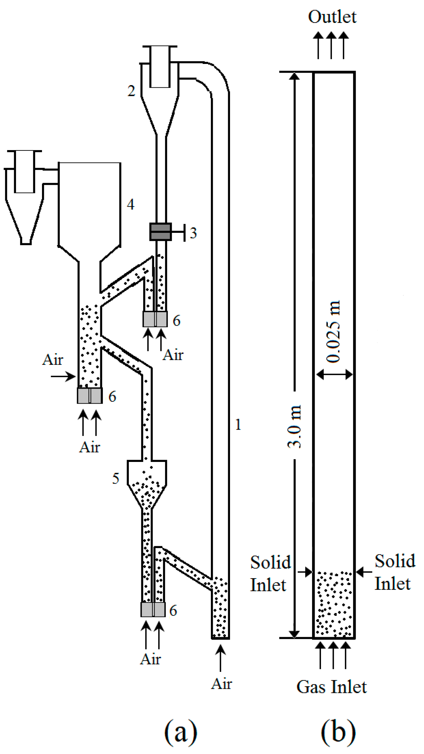
Figure 1. (a) Schematic diagram (a) CFB reactor (b) simplified 2D computational domain of CFB riser (1 —riser bed; 2—cyclone; 3—ball valves; 4—bubbling bed; 5—recirculation region; 6—loop-seal).
Chemengineering 04 00037 g001
Figure 2. CFB riser outlet mass flow rate as a function of time.
Chemengineering 04 00037 g002
Figure 3. Influence of drag models on the outlet mass flow rate.
Chemengineering 04 00037 g003
Figure 4. Time-averaged radial solid volume fraction for Syamlal-O’Brien, Gidaspow, Wen-Yu, Huilin-Gidaspow, Gibilaro and Helland drag models at height of (a) 1.5 and (b) 2 m.
Chemengineering 04 00037 g004
Figure 5. Influence of drag models (a) gas phase axial velocity (b) solid phase axial velocity at H = 1.5 m.
Chemengineering 04 00037 g005
Figure 6. Influence of drag models on the axial solid holdup profile.
Chemengineering 04 00037 g006
Figure 7. Root mean square error (RMSE) for six different drag model.
Chemengineering 04 00037 g007
Table 1. System geometry, gas and solid phase properties and flow condition.
DescriptionValue
CFB riser:
Diameter, D0.025 m
Height, H3.0 m
Fluidizing media properties:
Gas density, ρg1.225 kg/m3
Solid phase density, ρs2525 kg/m3
Particle mean diameter, dp130 μm
Flow condition:
Superficial gas velocity, Ug2 m/s
Solid particle flux, Gs39.14 kg/m2s
Table 2. Modeling parameters.
Particle–Wall and Particle–Particle Interactions Parameter Value:
Specularity coefficient (φ)-0.0001
Particle–wall restitution coefficient (ew)-0.9
Particle–particle restitution coefficient (ess)-0.9
Packing limit (αs,max)-0.63
Transient solver calculation and convergence criteria:
Time step (s)-0.0005
Convergence criteria-10−3
Maximum iterations per time step-50
Discretization schemes settings:
Momentum-1st order upwind
Volume fraction-1st order upwind
Transient formulation-1st order implicit
Table 3. Drag model correlations.
1. Syamlal-O’Brien: [26]
K s g = 3 α s α g ρ g 4 V r , s 2 d s C D ( R e s V r , s ) | V s V g |
where
C D = ( 0.63 + 4.8 R e s V r , s ) 2
V r , s = 0.5 ( A 0.06 R e s + ( 0.06 R e s ) 2 + 0.12 R e s ( 2 B A ) + A 2
A = α g 4.14
B = 0.8 α g 1.28   f o r   α g   0.85
B = α g 2.65     f o r   α g   > 0.85
R e s = ρ g d s | V s V g | μ g
2. Wen-Yu: [24]
K s g = 3 4 C D α s α g ρ g | V s V g | d s α g 2.65
where
C D = 24 α g R e s [ 1 + 0.15 ( α g R e s ) 0.687 ]
R e s = ρ g d s | V s V g | μ g
3. Gidaspow: [25]
K sg = 3 4 C D α s α g ρ g | v s v g | d s   α g 2.65      F o r   α g   > 0.8 ,
  K sg = 150 α s ( 1 α g ) μ g α g d s 2 + 1.75 α s ρ g | v s v g | d s         F o r   α g   0.8 ,
where
  C D = 24 α l R e s [ 1 + 0.15 ( α l R e s ) 0.687 ]
R e s = ρ g d s | V s V g | μ g
4. Huilin-Gidaspow: [33]
K sg = ψ K s g E r g u n + ( 1 ψ ) K s g W e n & Y u
Stitching function
Ψ = 1 2 + a r c t a n ( 262.5 ( α s 0.2 ) ) π
5. Gibilaro: [34]
K sg = ( 18 R e + 0.33 ) ( ρ g | v s v l | ) d p α s α l 1.8
6. Helland: [35]
K sg = 3 4 C D α s α g ρ g | v s v g | d s
where
  C D = C D , 0 C D , correction
  C D , 0 = 24 α l R e s [ 1 + 0.15 ( α l R e s ) 0.687 ]
R e s = ρ g d s | V s V g | μ g
  C D , correction = 924.8 1891.8 α g + 968 α g 2    f o r   α g 0.95
  C D , correction = α g 4.7    f o r   α g 0.95