Article

Optimization and Process Modeling of Plasma Gasifier via Aspen Plus and Surrogate Model for Treatment of Municipal Solid Waste

1
Experiment and Diagnostic Division, Pakistan Tokamak Plasma Research Institute, Islamabad 45650, Pakistan
2
Department of Chemical Engineering, Pakistan Institute of Engineering and Applied Sciences (PIEAS), Islamabad 45650, Pakistan
3
Interdisciplinary Research Center for Refining & Advanced Chemicals, King Fahd University of Petroleum & Minerals (KFUPM), Dhahran 31261, Saudi Arabia
4
Department of Chemical Engineering, King Fahd University of Petroleum & Minerals (KFUPM), Dhahran 31261, Saudi Arabia
*
Authors to whom correspondence should be addressed.
ChemEngineering 2026, 10(6), 77; https://doi.org/10.3390/chemengineering10060077
Submission received: 28 March 2026 / Revised: 13 May 2026 / Accepted: 22 May 2026 / Published: 16 June 2026

Abstract

Plasma gasification is a sustainable and advanced technology for the safe and efficient treatment of municipal solid waste (MSW). In this process, a plasma torch serves as the primary heating source to convert MSW into syngas and inert vitrified slag. The produced syngas can be used for various downstream applications, including power generation. In this study, an updraft plasma gasifier is modeled using the Aspen Plus process simulator, with municipal solid waste from Lahore, Pakistan, used as the feedstock. Air is selected as a plasma-forming gas due to its low cost and widespread availability. The primary aim of this research is to analyze the effect of specific torch power and the air-to-feed mass flow ratio on syngas molar composition, syngas higher heating value (HHV), and cold gas efficiency (CGE), and to maximize gasifier performance. CGE of the gasifier is optimized using a surrogate-based model integrated with a genetic algorithm (GA). An artificial neural network (ANN) is employed as the surrogate model for the optimization of CGE. The novelty of this work lies in two key aspects: firstly, this is among the first studies to specifically model and simulate plasma gasification of Lahore’s MSW, capturing its unique waste composition characteristics; and secondly, the integration of process simulation with a data-driven optimization framework using an ANN surrogate model. A total of 1521 data points were generated from the Aspen Plus simulation to train the ANN model and perform optimization in MATLAB. The optimized CGE was found to be 90.6%. Validation of the ANN-GA optimization was carried out by implementing the optimized input parameters in the Aspen Plus gasifier model. The resulting CGE shows a percent relative error of only 0.11% compared to the MATLAB-predicted value, confirming the accuracy of the surrogate model. Furthermore, comparison with the base case simulation reveals that the optimized operating conditions lead to an 8.6% increase in cold gas efficiency, demonstrating the effectiveness of the proposed optimization approach.

1. Introduction

Global waste generation has increased significantly over the past few decades, driven by rapid urbanization, industrialization, and population growth, with no indication that this trend will decline in the near future [1]. Currently, more than two billion tons of municipal solid waste (MSW) are generated annually worldwide [2], and this quantity is projected to increase by nearly 70% (3.4–3.9 billion tons) by 2050. The waste sector is also a major contributor to global greenhouse gas emissions, particularly methane emissions from landfills, which possess a much higher global warming potential than carbon dioxide. According to global estimates, solid waste disposal contributes approximately 20% of anthropogenic methane emissions worldwide [3]. As waste generation escalates, the safe and environmentally sustainable management of MSW has become a critical global challenge [4]. Pakistan generates more than 49.6 megatons of urban solid waste each year, with an annual growth rate exceeding 2.4% [5]. Similar to many developing countries, Pakistan faces significant challenges in waste management infrastructure, resulting in severe environmental and public health concerns [6]. Conventionally, MSW is managed through open dumping, burning, or disposal in unregulated landfills, practices that pose serious risks to human health and environmental quality [7]. According to government estimates, approximately 87,000 tons of MSW are produced weekly, with most of it produced in major metropolitan areas [8]. Karachi, Pakistan’s largest city with an estimated population of 20 million [9], generates more than 16.5 kilotons of municipal waste per day [10]. Consequently, MSW management presents a major challenge for large urban centers across the country [11,12].
In Pakistan, the limited availability of engineered landfill sites and the high cost of waste transportation further complicate MSW management [13]. As a result, conventional disposal methods such as open dumping and uncontrolled burning remain prevalent [14]. These practices lead to extensive land occupation, greenhouse gas (GHG) emissions, groundwater contamination, and serious environmental and health hazards [15]. In 2018, Pakistan’s total GHG emissions reached 428.6 million tons of carbon dioxide equivalent (MtCO2e) [16], ranking the country as the 18th highest global emitter according to the Climate Analysis Indicators Tool (CAIT) database of the World Resources Institute (WRI) [17]. In response, Pakistan has pledged to reduce its GHG emissions by up to 20% by 2030 [18]. One effective strategy to achieve this target is the mitigation of environmental impacts associated with MSW generation and disposal in urban areas [19]. Waste-to-energy (WtE) technologies offer a viable pathway for energy recovery from MSW while reducing the environmental burden compared to conventional landfilling [20,21]. In addition to lowering emissions, MSW-based energy recovery can create employment opportunities [22] and contribute to the diversification of the national energy mix [23]. Energy recovery from MSW can be achieved using both biochemical and thermochemical conversion routes [24]. Conventional WtE technologies include incineration, gasification, fermentation, and anaerobic digestion [25]. Among these, incineration has been the most widely adopted technology due to its capability to process heterogeneous waste streams [26,27]. Compared to landfill disposal, incineration offers advantages such as reduced pollution, higher energy recovery potential, and significant waste volume reduction [28]. However, incineration is also associated with notable drawbacks, including the generation of residual ash and the emission of harmful pollutants such as HCl, SOₓ, NOₓ, dioxins, furans, and particulate matter, which pose risks to environmental and human health [29,30].
Plasma gasification has recently emerged as an advanced alternative for energy recovery from municipal solid waste [31]. In plasma gasification, an external energy source is employed to generate a high-temperature plasma jet [32]. Under oxygen-deficient conditions, organic components of the feedstock undergo thermal decomposition to produce synthesis gas (syngas), while the inorganic fraction is transformed into molten, vitrified slag [33]. The use of an external energy source in plasma gasification offers several advantages, including enhanced syngas quality, low tar formation, high feedstock flexibility for heterogeneous solid fuels, minimal dioxin and furan emissions, and the conversion of inorganic residues into an inert, non-hazardous slag [34,35,36]. Numerous studies have used thermochemical equilibrium models to evaluate the plasma gasification process as a viable route for energy recovery from MSW and other biomass feedstocks [37]. Khuraiti et al. [38] investigated the influence of air–steam mixtures as plasma-forming gases during MSW gasification using waste from the Jatibarang landfill in Indonesia. Their gasification model was based on Gibbs free energy minimization using the Lagrange multiplier method. The results indicated that cold gas efficiency (CGE) increased with a higher steam fraction in the air-steam mixture. Qinglin et al. [39] experimentally examined the effects of operating parameters on CGE, lower calorific value, and syngas yield using a pilot-scale, moving-bed, updraft plasma gasification melter. This study also analyzed the characteristics of the vitrified slag formed at the bottom of the reactor. Plasma torches installed near the air nozzles increased the inlet air temperature to approximately 6000 °C. The pilot plant was designed for a processing capacity of up to 20 tons/day of MSW, and the CGE for both steam and air gasification approached 60%. Armin et al. [40] studied plasma gasification using a blended feedstock of solid waste and coal to evaluate the effects of gasifier temperature, equivalence ratio, waste-to-coal mixing ratio, and steam-to-solid waste ratio on syngas composition. Steam, pure oxygen, and air were used as plasma sources. The gasifier was modeled in Aspen Plus using a thermodynamic equilibrium approach. A maximum CGE of approximately 60% was achieved at a biomass fraction of 0.5 and an equivalent ratio of 0.4.
Although the present study primarily focuses on thermodynamic modeling and optimization of plasma gasification performance, the obtained results also indicate important practical and environmental implications. Compared with conventional incineration and landfilling technologies, plasma gasification offers improved waste volume reduction, enhanced syngas quality, and lower formation of hazardous byproducts due to the extremely high operating temperatures. In addition, the vitrified slag generated during plasma gasification can potentially be utilized in construction applications, reducing secondary waste disposal requirements. However, plasma gasification systems generally involve higher electrical energy consumption and operational costs because of plasma torch operation. Therefore, the economic viability of such systems strongly depends on energy recovery efficiency, local electricity costs, waste management policies, and plant scale. Furthermore, although plasma gasification can reduce direct landfill-related methane emissions and minimize dioxin formation compared with conventional thermal treatment technologies, a detailed assessment of gaseous emissions such as CO2 and NOx requires comprehensive experimental and techno-environmental investigation. Future work should therefore focus on integrated techno-economic analysis, life cycle assessment, and environmental emission evaluation to assess the industrial feasibility of plasma gasification systems for large-scale municipal solid waste treatment.
The primary objective of this research is to evaluate the influence of key operating parameters―namely, specific torch power (defined as the ratio of torch power to feed mass flow rate) and air-to-feed mass flow ratio―on syngas quality, including molar composition, higher heating value (HHV), and CGE, with the goal of enhancing overall gasification performance. A comprehensive parametric analysis is conducted to establish the relationships between input variables and gasifier outputs. Although Aspen Plus has been widely applied for modeling plasma gasification systems, limited studies have focused on region-specific municipal solid waste, particularly MSW from Lahore, Pakistan. Furthermore, the integration of Aspen Plus simulation with hybrid Artificial Neural Network–Genetic Algorithm (ANN-GA) frameworks for optimizing CGE remains largely unexplored in this context. This study addresses these gaps by conducting a detailed technical evaluation of syngas production from an updraft plasma gasifier using Lahore’s MSW and by optimizing its thermal performance through surrogate modeling. The simulation framework used in this work is based on the plasma gasifier model proposed by Montiel et al. [41].

2. Materials and Methods

2.1. Materials Used

The Aspen Plus process simulator (version V10) was used for the simulation of the updraft gasifier model in this study. Optimization of CGE was performed using MATLAB (R2020a). In this study, MSW generated in Lahore, Pakistan, was used as the feedstock. Lahore produces approximately 7150 tons of MSW per day; however, systematic waste disposal is limited due to the lack of (a) pre-planning, (b) adequate landfill infrastructure, (c) governmental enforcement, and (d) public awareness. The HHV of this MSW was reported as 22,570 kJ/kg [42]. Ultimate and proximate analyses of the feedstock are presented in Table 1.

2.2. Simulation Model

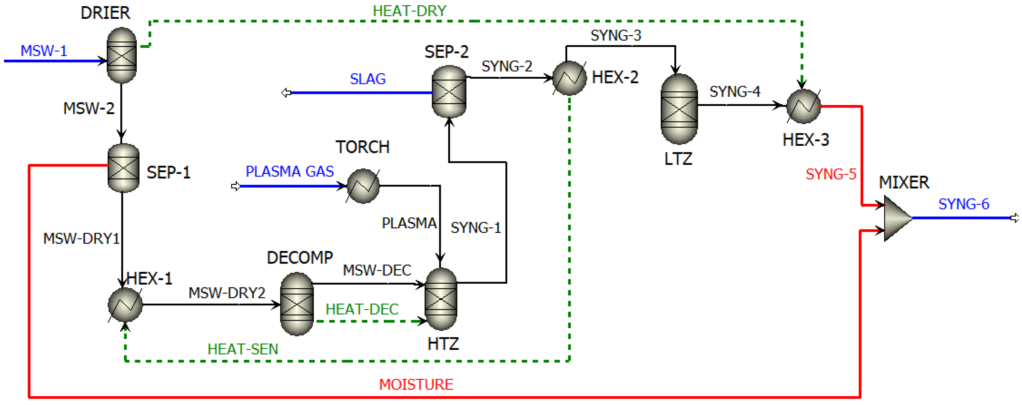
The plasma gasification (PG) model developed in this study (Figure 1) is based on several key assumptions: steady-state operation, a perfectly insulated reactor vessel [43], ideal mixing within the gasifier [44], negligible tar formation [34], and thermochemical equilibrium for all gasification reactions [45]. The present study employs a thermodynamic equilibrium-based Aspen Plus® model to evaluate the performance of the plasma gasification system. Although equilibrium models are widely used due to their computational efficiency and ability to predict general gasification trends, they involve certain simplifications that may differ from real operating conditions. The assumptions of complete thermodynamic equilibrium, perfect mixing, and adiabatic operation neglect kinetic limitations, heat losses, and hydrodynamic effects occurring in practical gasifiers. In addition, tar formation is not explicitly modeled because the equilibrium approach assumes complete cracking of heavy hydrocarbons at the elevated temperatures generated within the plasma gasification zone. Consequently, the predicted syngas composition and CGE may be somewhat overestimated compared to real systems. Nevertheless, the model provides valuable insight into the influence of operating parameters on gasifier performance and serves as an effective tool for process analysis and optimization. Furthermore, sensitivity analysis of key operating parameters, including specific torch power and air-to-feed ratio, was performed to evaluate the robustness and consistency of the model predictions over a wide operating range. The overall gasification reaction considered in this work can be expressed as:
C n H m O p N q S r + a ( O 2 + 3.76 N 2 ) x H 2 + y C O + z C H 4 + w C O 2 + v H 2 O + u N 2 + l H 2 S + k C O S
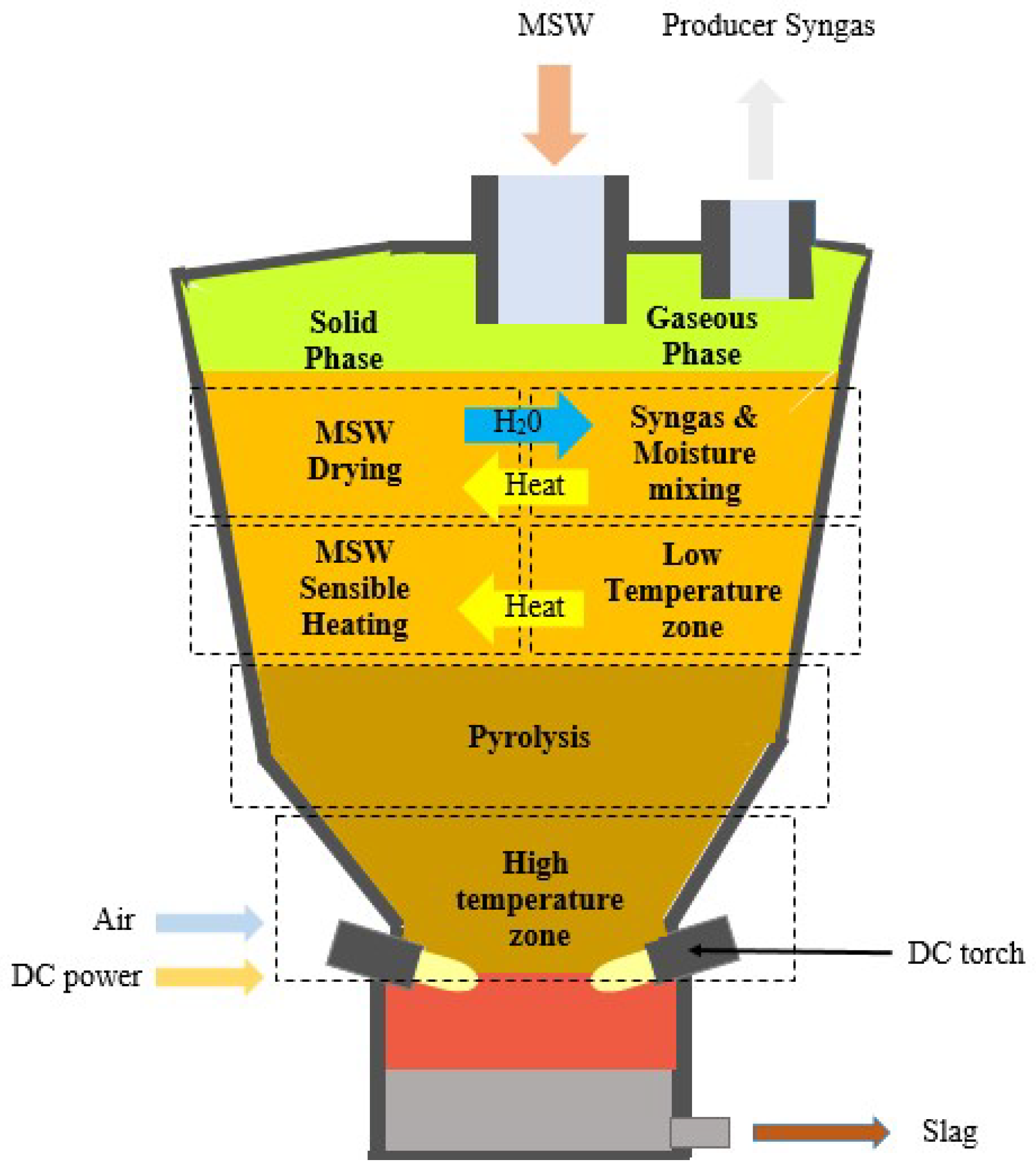
MSW enters the gasification chamber through the top inlet, as shown in Figure 2. As the feedstock descends, it is preheated by the upward flow of hot product gas (syngas), resulting in an increase in its sensible heat. Moisture present in the waste is evaporated when the temperature approaches approximately 110 °C, and the released water vapor mixes with rising syngas in the upper section of the gasifier. Following the drying stage, the temperature of the dehydrated MSW continues to rise due to heat transfer from the counter-current syngas stream as it moves downward through the reactor. Upon entering the high-temperature zone near the plasma torches, the organic fraction of the waste undergoes rapid thermal decomposition and gasification, producing syngas, while the inorganic fraction melts and forms vitrified slag.
Based on the temperature distribution inside the reactor, the gasifier is conceptually divided into two distinct reaction zones. The first zone corresponds to the high-temperature region adjacent to the plasma torches, where intensive MSW decomposition and gasification occur [46,47]. The second zone represents the upper section of the reactor, where secondary gas-phase reactions take place at comparatively lower temperatures within the syngas flow. This dual-zone modeling strategy has been successfully applied in previous studies investigating plasma gasification of various solid fuels [46,47,48]. However, compared with earlier models, the present work introduces several modifications to provide a more comprehensive representation of an updraft plasma gasifier operating on municipal solid waste.
The key advantages of the proposed plasma gasification model are as follows:
(i)
The model assumes tar-free syngas at the outlet due to the high-temperature plasma environment, which enables effective thermal cracking and reforming of heavy hydrocarbons.
(ii)
The updraft plasma gasifier configuration is well-suited for heterogeneous MSW, offering enhanced heat recovery and higher CGE. The incorporation of plasma technology mitigates tar formation, thereby combining the operational advantages of updraft systems with improved syngas quality.
(iii)
The heat balance explicitly accounts for the energy required for waste dehydration. This drying energy is used to heat the MSW to the drying temperature (110 °C), enabling complete evaporation of inherent moisture.
(iv)
This model captures energy transfer between the ascending syngas stream and the descending MSW after dehydration. This counter-current heat exchange continues until the waste reaches the plasma torch zone.
(v)
Both thermal and chemical equilibrium analyses are incorporated for the inorganic fraction of the waste.
The reactions taking place in the gasifier are shown in Equations (2)–(7) below.
C H 4 + H 2 O C O + 3 H 2
C + H 2 O C O + H 2
C + C O 2 2 C O
C + ½ O 2 C O
C O + ½ O 2 C O 2
H 2 + ½ O 2 H 2 O
The Peng–Robinson equation of state was employed as the thermodynamic property method. The HCOALGEN and DCOALIGT models were used to estimate the enthalpy and density of non-conventional components such as MSW. An RYIELD block (DRIER) was used to model MSW drying, where the waste enters as a non-conventional component. The dried MSW yield and separated moisture were obtained from the dryer block. The heat required for drying was supplied through heat transfer from the syngas stream (SYNG-4), modeled using a heater block (HEX-3). The HEX-3 block is connected to the DRIER via an energy stream (HEAT-DRY), allowing the sensible heat of the syngas to raise the MSW temperature to 110 °C. Consequently, the temperature of the syngas stream decreases.
The moisture separated in the DRIER was subsequently mixed with the outgoing gas stream (SYNG-5) using a MIXER block. The dried MSW (MSW-DRY1) continues to descend and undergo further heating. This stage was modeled using two heater blocks (HEX-1 and HEX-2) and an energy stream (HEAT-SEN), representing sensible heat exchange between the rising syngas stream (SYNG-2) and the dried waste. The thermally conditioned MSW (MSW-DRY2) was then decomposed in an RYIELD block (DECOMP), where it was converted into its elemental constituents (C, H, O, N, and S) based on ultimate and proximate analyses [46].
The plasma torch was modeled using a heater block (TORCH) to generate a high-energy plasma jet. Electrical power input was specified for the torch, and a torch efficiency of 80% was assumed. The decomposed waste stream (MSW-DEC) and plasma stream were fed into the high-temperature zone (HTZ), modeled using an RGibbs block. Gasification reactions occurred in the HTZ to produce syngas and molten slag, with the system simulated based on Gibbs free energy minimization under thermochemical equilibrium conditions [48]. An energy stream (HEAT-DEC) was included to account for energy exchange between the decomposer and the HTZ block. A separator block was used to separate the syngas stream (SYNG-2) from the slag (SLAG). The syngas temperature was reduced by passing it through HEX-2, and the recovered energy was utilized to heat the dried MSW. The low-temperature zone (LTZ) was also modeled using the RGibbs block based on Gibbs free energy minimization [49]. The gaseous species considered in the model include CH4, CO, CO2, H2, H2S, N2, COS, and O2. Finally, the moisture released during the dehydrating stage was merged with the syngas stream (SYNG-5). A detailed description of the Aspen Plus blocks used in the plasma gasification model is provided by Bohórquez et al. [41]. The model was previously validated against experimental data from Perna et al. [47] and numerical results from Minutillo et al. [34] by Montiel-Bohórquez et al. [41].

2.3. Thermodynamic Performance

The thermodynamic performance of the PG model is evaluated using the CGE. CGE represents the ratio of the useful chemical energy recovered in the produced synthesis gas to the total energy input to the gasifier, which includes both the chemical energy of the waste feedstock and the electrical energy supplied to the plasma torch [50]. The CGE of the gasifier is calculated using Equation (8) [51].
C G E = m ˙ s y n g a s . H H V s y n g a s m ˙ M S W . H H V M S W + W ˙ T o r c h
The plasma torch power is determined from the electrical power supplied to generate the plasma jet and the torch efficiency, as expressed in Equation (9). In this study, a torch efficiency of 80% is assumed [52].
W ˙ T o r c h = W ˙ P l a s m a η t o r c h

2.4. Simulation Plan

The plasma gasification process was simulated using air as the plasma-forming gas. Initially, a base case operating condition was established and subsequently used as a reference for comparison with the optimized results. The base case was simulated with an air-to-feed mass ratio of 1.375 and a specific torch power of 1665 kJ/kg. The electrical torch power is 144.5 kW, resulting in a plasma temperature of 1363.5 °C. However, the temperature of HTZ and LTZ reaches 2000 °C and 1800 °C, respectively, due to the exothermic reactions taking place. The operating parameters of the base case gasifier model are summarized in Table 2.
Using the base case configuration, the effects of the air-to-feed mass ratio and the specific torch power (defined as the ratio of effective torch power to MSW mass flow rate) were systematically investigated. Their influence on syngas molar composition, syngas HHV, and CGE was analyzed.

2.5. Surrogate Optimization Model

Rigorous optimization of an integrated plasma gasification system is computationally expansive and complex due to the strong nonlinear interactions among operating parameters. To overcome this limitation, a substitute (surrogate) model based on machine learning is developed to analyze and optimize the gasification process within an integrated optimization framework [53]. In surrogate modeling, the actual process is treated as a black box that approximates the input–output behavior of the system. In the present work, the entire plasma gasification process is represented using a surrogate model. The development of a surrogate model involves two key steps: (i) data sampling and (ii) construction of the surrogate model using the sampled data.

2.5.1. Data Sampling

The first step in surrogate model development is the selection of relevant input and output variables, as the accuracy of the surrogate strongly depends on the quality and relevance of the data used for training. Data can be obtained either experimentally or from a simulation-based process model. In this study, data were generated using the validated Aspen Plus plasma gasification model. The selected input variables include the MSW mass flow rate, air-to-feed mass flow ratio, and specific torch power. The corresponding output variables of interest are the mass flow rate of slag and the HHV of the produced syngas. A total dataset comprising 1521 data points was generated by systematically varying the selected input parameters within predefined ranges. The ranges of the input variables considered for optimization are summarized in Table 3.

2.5.2. Construction of Process Surrogate Model

Several surrogate modeling techniques reported in the literature can be employed to approximate the nonlinear input–output relationship of a process. These include ANN, Multiple Linear Regression (MLR), Linear Support Vector Regression (LSVR), Gaussian Support Vector Regression (GSVR), and Quadratic Support Vector Regression (QSVR). To identify the most suitable surrogate model, their performance was evaluated using two statistical metrics: the coefficient of determination (R2) (Equation (10)) and the root mean square error (RMSE) (Equation (11)), defined as follows:
R 2 = 1 i = 1 n y i e x p y i p r e d i c t i o n 2 i = 1 n y i e x p y a v g e x p 2
R M S E = i n y i e x p y i p r e d i c t i o n 2 n
where y i e x p   represents the actual output value obtained from the Aspen Plus simulation and y i p r e d i c t i o n denotes the corresponding value predicted by the surrogate model. For accurate surrogate construction, separate models were trained and validated for each output variable, namely slag mass flow rate and syngas HHV.
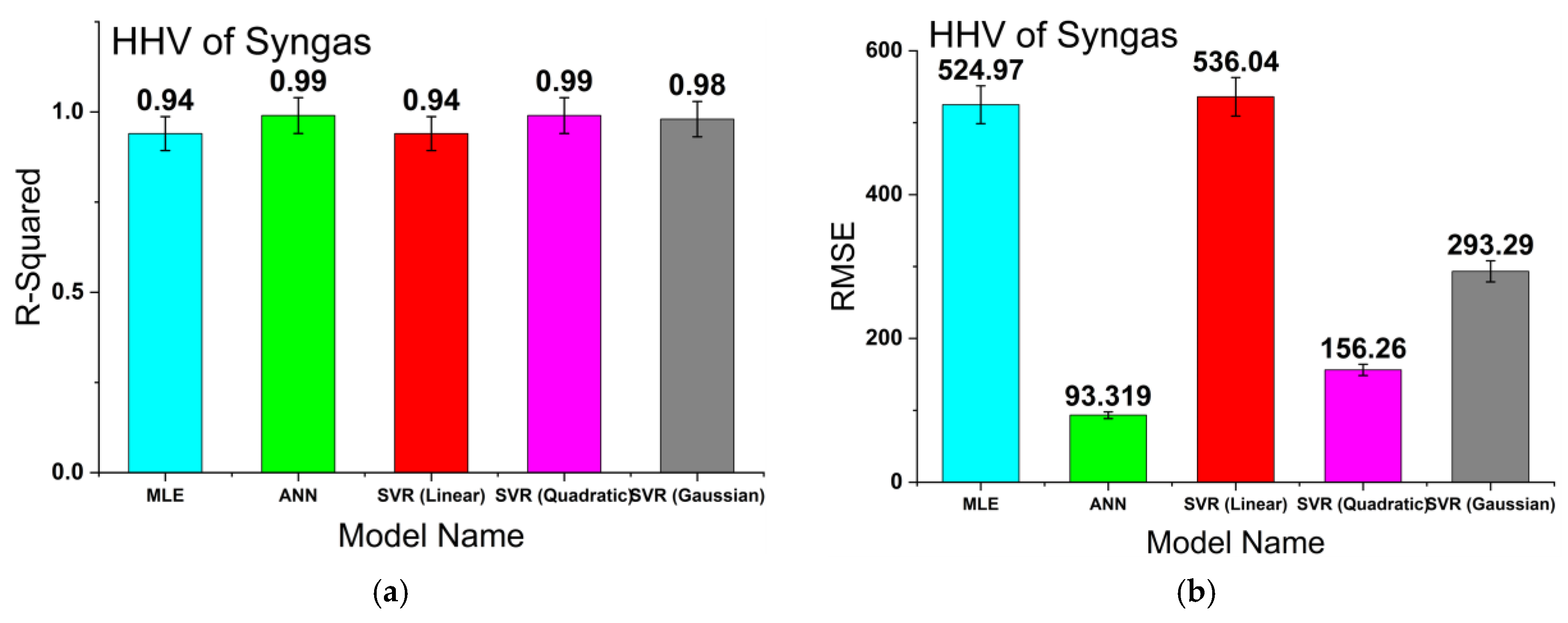
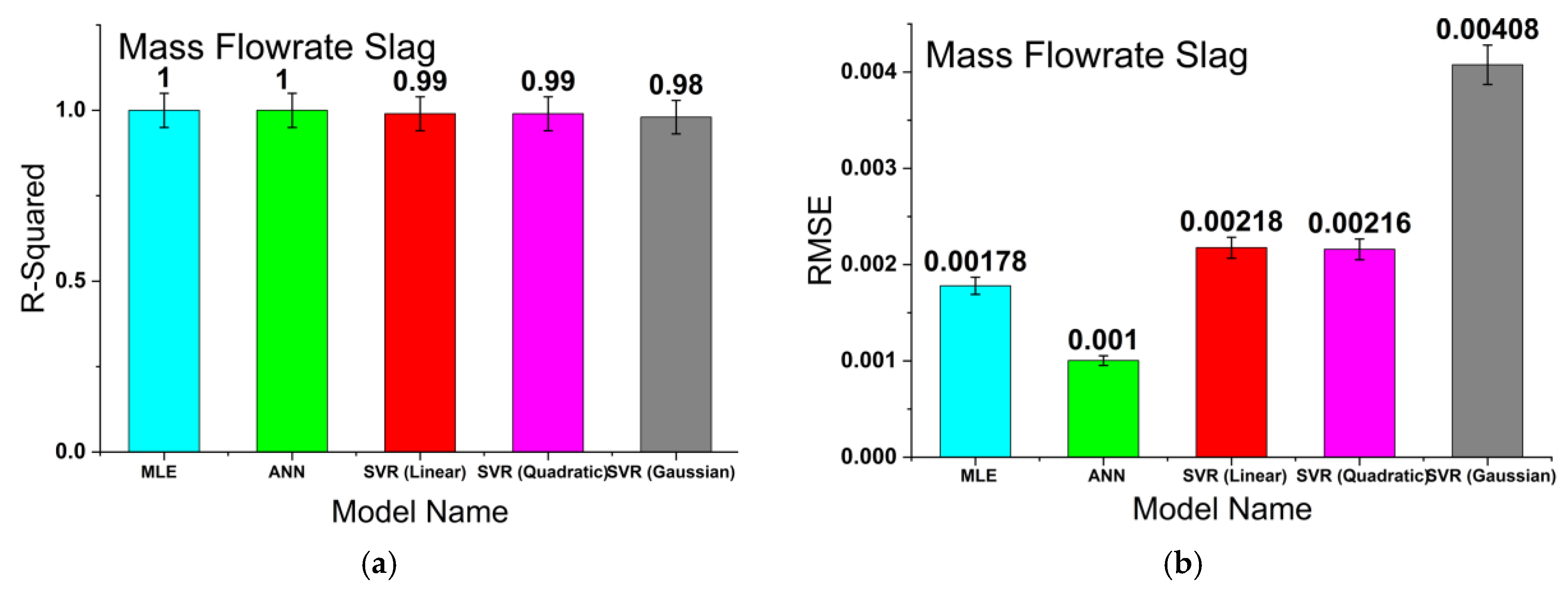
The regression learner App in MATLAB R2019b was used to train and validate all candidate surrogate models. MATLAB was dynamically linked with the dataset stored in an Excel file. Based on the performance metrics, the ANN surrogate model demonstrated superior predictive capability compared with the other surrogate models evaluated in this study. As shown in Figure 3a, the ANN model achieved a high coefficient of determination (R2 ≈ 1.0) for predicting slag mass flow rate, indicating excellent agreement between predicted and simulation data. Furthermore, Figure 3b shows that the ANN model produced the lowest root mean square error (RMSE), confirming its higher prediction accuracy and robustness relative to the MLE and SVR-based models. Figure 4a illustrates that the ANN model achieved one of the highest R2 values, demonstrating strong predictive reliability for HHV estimation. In addition, Figure 4b indicates that the ANN model yielded the minimum RMSE value, significantly lower than those obtained using MLE and SVR (Linear, Quadratic, and Gaussian) models. These results confirm that the ANN model provides more accurate nonlinear mapping between gasifier operating parameters and output responses, making it highly suitable for the optimization of plasma gasification systems. The relatively lower performance of other models indicates the highly nonlinear nature of the data generated from the integrated Aspen Plus flowsheet. This enhanced performance of ANN is attributed to its hidden-layer neurons, which are capable of capturing complex nonlinear relationships in high-dimensional input space. Moreover, the ANN model is well suited for developing accurate and compact representations of multi-input, multi-output systems [54]. The specifications of the developed ANN model are presented in Table 4. The ANN surrogate model employed in this study consisted of a feedforward neural network trained using the Levenberg–Marquardt optimization algorithm. The complete dataset generated from Aspen Plus® simulations was divided into training, validation, and testing subsets in the ratio of 70%, 15%, and 15%, respectively, to ensure proper model generalization and minimize overfitting. The ANN architecture utilized 10 hidden neurons for predicting slag mass flow rate and 10 hidden neurons for predicting syngas HHV. The predictive performance of the developed ANN models was evaluated using statistical indicators, including the coefficient of determination (R2) and root mean square error (RMSE), which demonstrated excellent agreement between predicted and simulation results. The number of hidden neurons was selected based on minimizing the RMSE during training [55].
Based on the trained surrogate model, the optimization problem is formulated as follows:
m a x f x = ( A i r f u e l + f u e l     s l a g f u e l ) H H V   o f   S y n g a s H H V   o f   F u e l + S p e c i f i c   T o r c h P o w e r
s . t . m ˙ s l a g = A N N 1 x
H H V s y n = A N N 2 x
where x represents the vector of input parameters generated from the Aspen Plus simulations, as defined in Table 4.

2.6. Optimization Algorithm

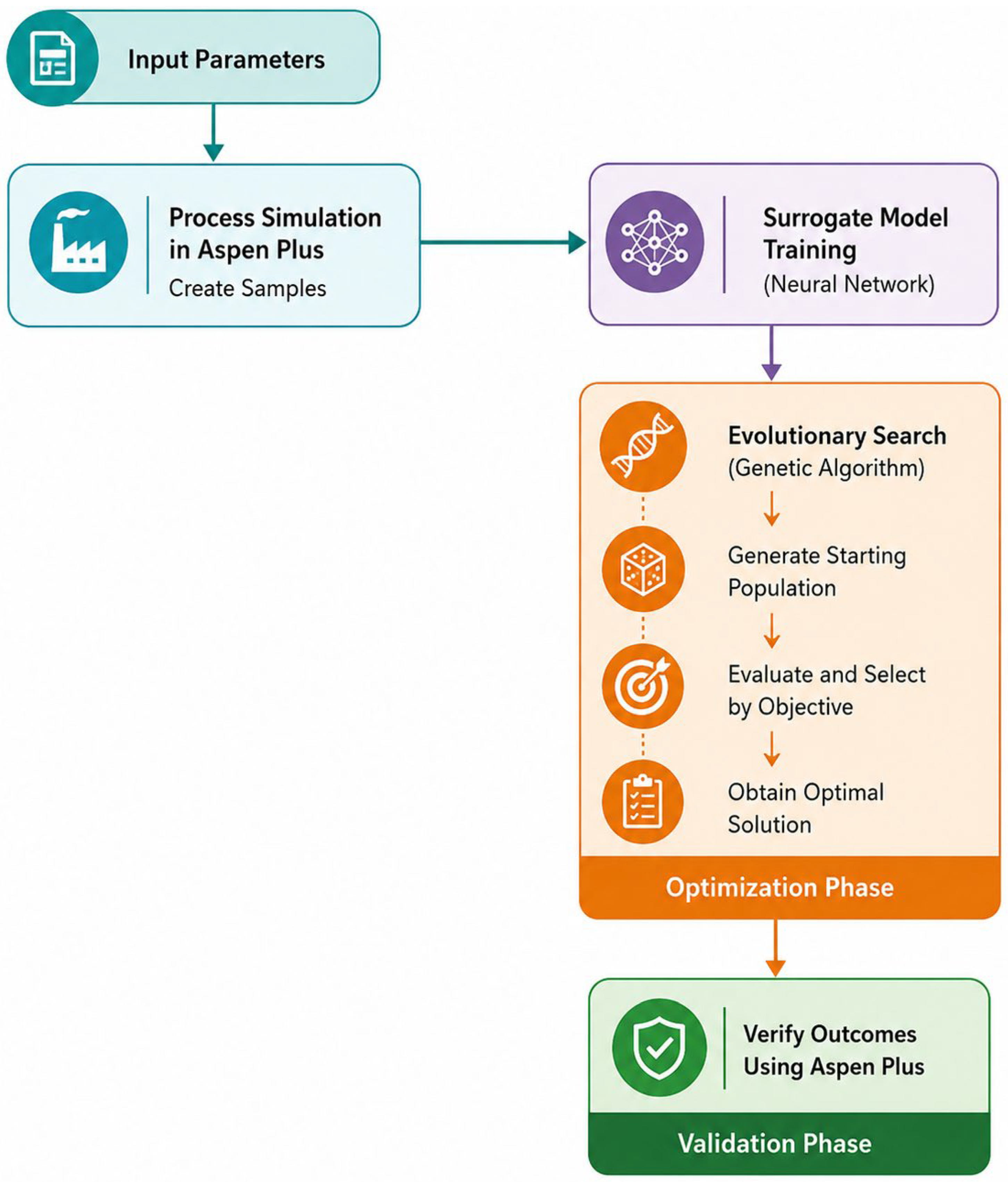
To optimize the integrated system, an appropriate optimization methodology is required. In the present study, a genetic algorithm (GA) was employed as the optimizer. GA is a stochastic optimization technique that is particularly effective for identifying global optimum solutions in complex, nonlinear systems. The GA operates through four fundamental steps executed sequentially in each optimization cycle: (i) random generation of the initial population, (ii) evaluation of the fitness value of each individual in the population based on a predefined fitness function, (iii) selection of the best-fitted individuals, and (iv) reproduction of new solutions (offspring) using crossover and mutation operations [56]. These steps are repeated in every generation (i.e., a complete optimization cycle) until a termination condition is satisfied [57]. In the present work, the termination criteria were defined based on MaxStallGenerations and constraint violation limits. The optimized values of the independent variables obtained from the ANN-GA-based optimization algorithm were subsequently used as input parameters in the Aspen Plus® flowsheet simulation. This step served two purposes: (i) optimization of the plasma gasification process flowsheet and (ii) validation of the ANN model by examining flowsheet convergence and assessing whether the ANN predictions provide physically plausible system behavior. The overall integrated ANN-GA optimization framework is shown in Figure 5.

3. Results and Discussion

This section presents and discusses the simulation results obtained from the base case, followed by a parametric analysis to investigate the influence of key operating parameters on system performance. Finally, the results of the optimization study are discussed.

3.1. Results of Base Case Simulation

The plasma gasifier simulation methodology was discussed in detail in the previous section, along with the input conditions used for the base case simulation. The results of the gasifier simulation for the base case are summarized in Table 5 and Table 6.
As shown in Table 5, the syngas primarily consists of hydrogen and carbon monoxide, which together constitute the dominant combustible components. Nitrogen remains inert and appears in high concentration due to the use of air as the plasma gas. All of the carbon and sulfur are converted into different gaseous species, leaving no traces of carbon and sulfur behind. This is due to the fact that plasma gasification results in efficient conversion of atomic carbon into HHV species. As evident from the results, plasma gasification results in minimal formation of hazardous acid gases like H2S and COS. All other species are present only in trace amounts. The high fractions of H2 and CO contribute significantly to the elevated heating values of the produced syngas. For the base case, a CGE of approximately 80–82% was achieved, as shown in Table 6. This value is further improved in the subsequent optimization analysis.

3.2. Parametric Study

A parametric study was conducted to evaluate the effects of key parameters, specifically, specific torch power and air-to-feed mass flow ratio, on syngas’ molar composition, HHV of syngas, and CGE.

3.2.1. Influence of Specific Torch Power

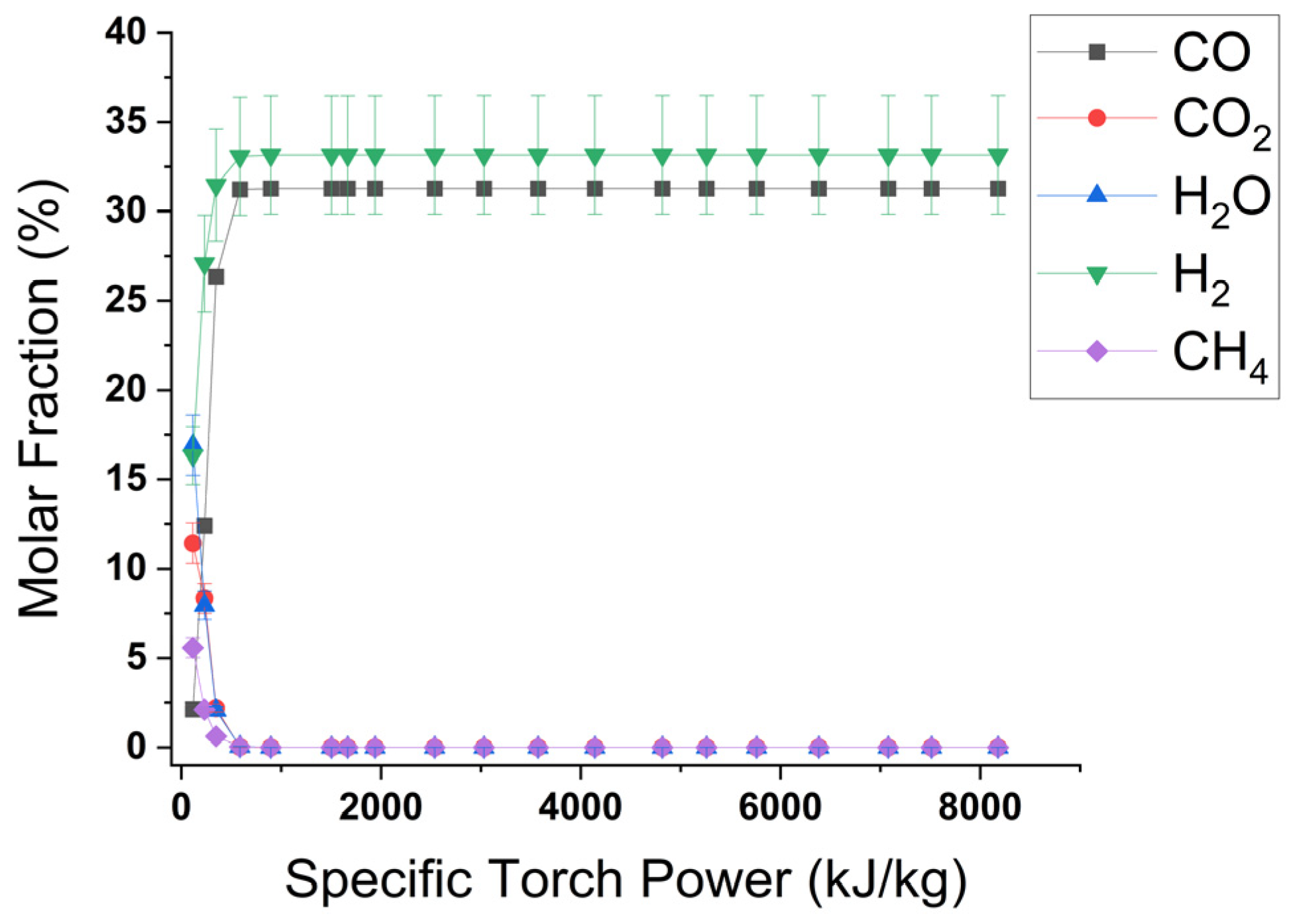
The effect of specific torch power (defined as the ratio of torch power to fuel mass flow ratio) was examined using sensitivity analysis. During this analysis, the air-to-feed mass flow ratio was maintained at a constant value of 1.375, corresponding to the base case condition. An increase in specific torch power leads to a rise in the temperature of the HTZ within the gasifier. This occurs because higher torch power increases the temperature of the plasma gas. The higher HTZ temperature promotes endothermic reactions, including methane steam reforming, carbon-steam reforming, and the Boudouard reaction, as described by Equations (2)–(4) in Section 2.2. As a result, the mole fractions of hydrogen and carbon monoxide in the syngas increase, while the concentrations of other components decrease, as shown in Figure 6.
The maximum H2 and CO mole fractions were observed at a specific torch power of 586 kJ/kg. Beyond this value, a further increase in torch power showed no significant impact on syngas composition. The relationship between specific torch power and syngas mole fraction is illustrated in Figure 6.
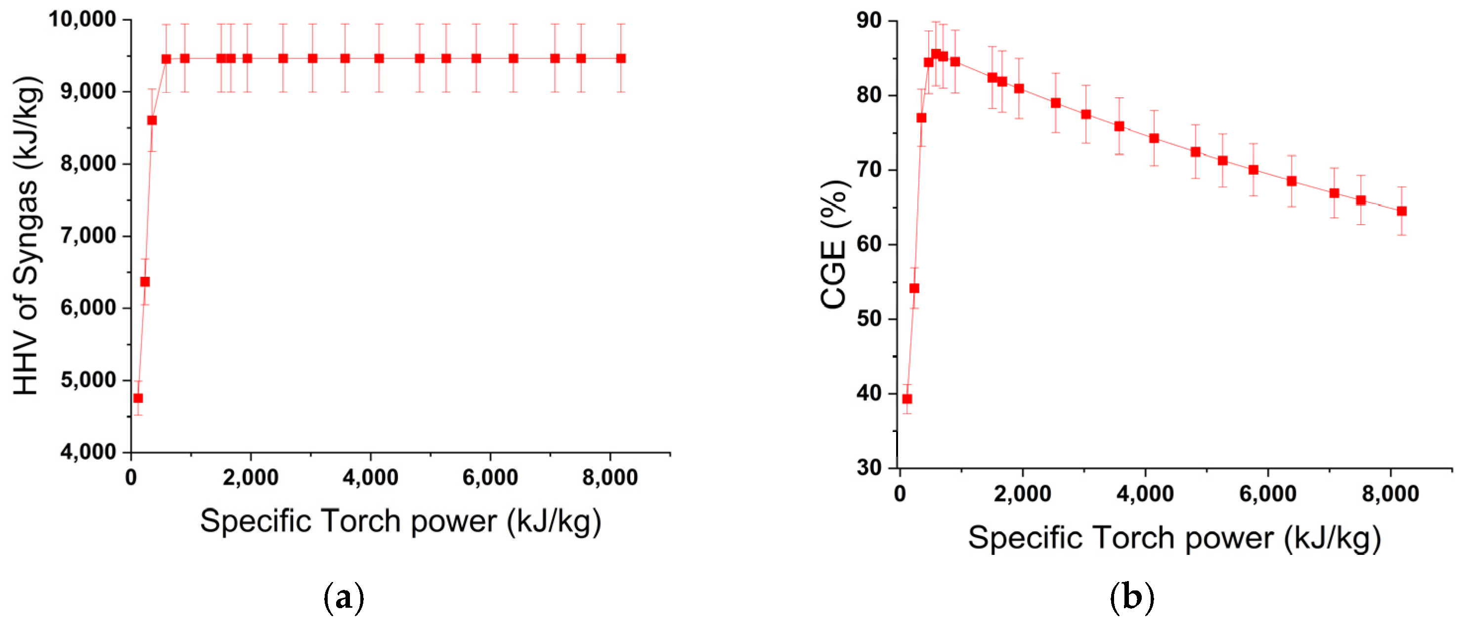
As the molar concentrations of H2 and CO increase in the syngas stream, the HHV of the produced syngas increases correspondingly, resulting in an improvement in CGE, as shown in Figure 7. Figure 7a illustrates that the HHV of syngas increases with increasing specific torch power due to the enhancement of endothermic reforming reactions at elevated gasification temperatures. The HHV reaches a maximum at a specific torch power of approximately 586 kJ/kg, beyond which further increases in torch power produce negligible improvement in syngas quality.
Similarly, Figure 7b shows that the CGE initially increases with specific torch power and attains a maximum value of nearly 85% at 586 kJ/kg. Beyond this operating point, CGE begins to decrease because the additional electrical energy supplied to the plasma torch does not result in a proportional increase in syngas HHV. This indicates the existence of an optimum torch power range for efficient plasma gasification operation, where maximum energy conversion efficiency can be achieved with minimal excess power consumption.

3.2.2. Influence of Air-to-Feed Mass Flow Ratio

The effect of air-to-feed mass flow ratio on syngas composition and performance parameters was examined through sensitivity analysis. In this study, the specific torch power was maintained constant at 1664 kJ/kg, while the air-to-feed ratio was varied, with the base case serving as the reference condition. An increase in airflow rate leads to a higher availability of oxygen, which promotes oxidation reactions within the gasifier, as shown in Equations (5)–(7) in Section 2.2.
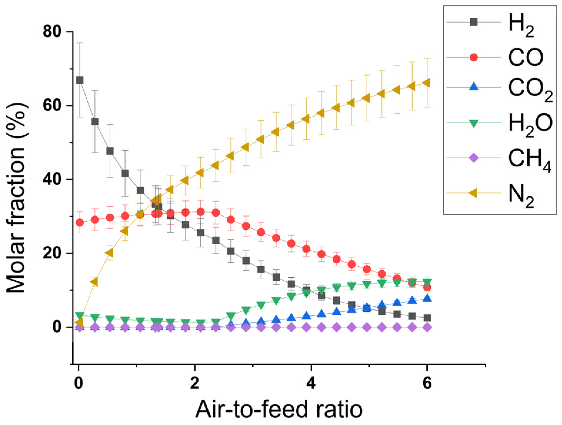
As a result of these reactions, the molar concentration of hydrogen decreases in the synthesis gas stream owing to the reaction of H2 with O2 to synthesize water. The molar composition of CO initially increases slightly because of carbon oxidation (Equation (5)), as shown in Figure 8. However, with further increases in airflow rate, CO undergoes oxidation to CO2 (Equation (6)), leading to a sharp reduction in CO concentration and a corresponding increase in CO2 mole fraction. The effect of air-to-feed ratio on the molar fraction of syngas is shown in Figure 8.
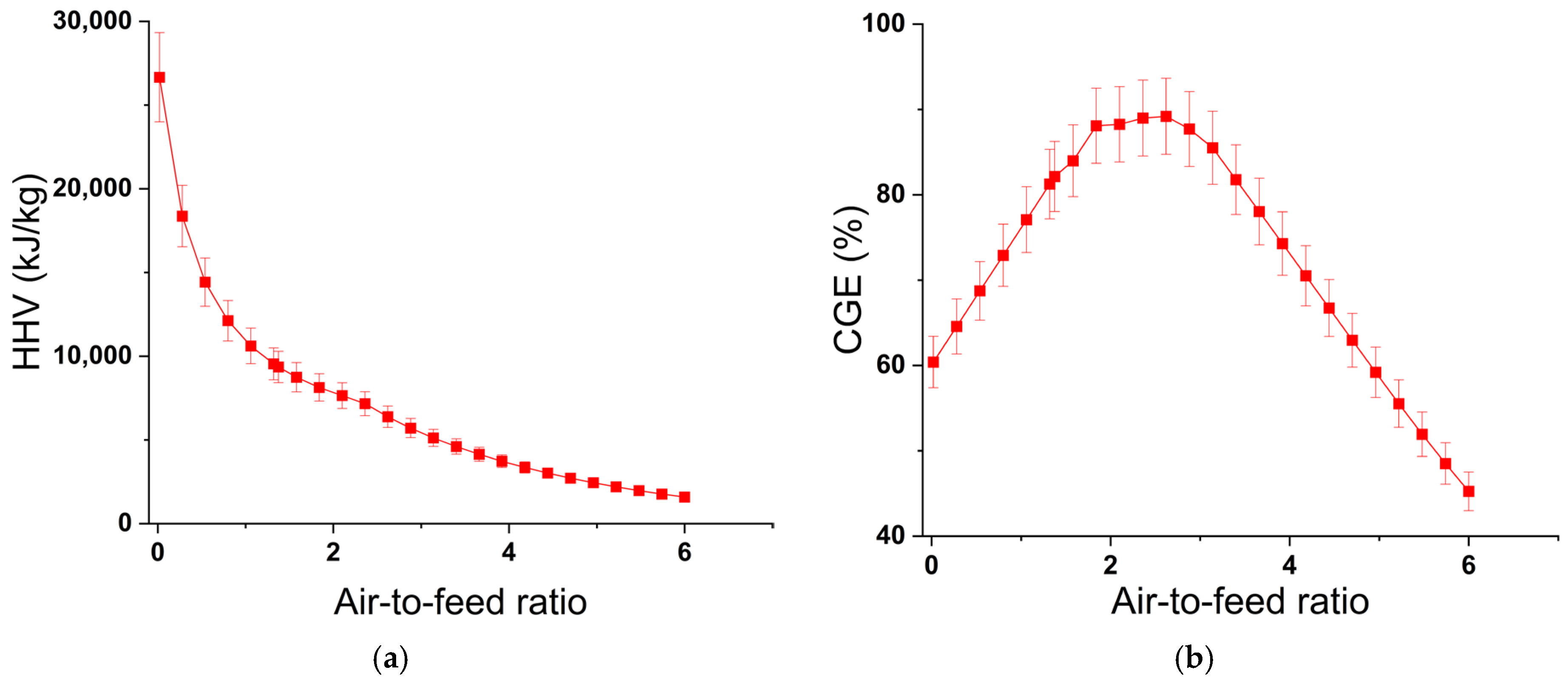
As shown in Figure 9a, an increase in the air-to-feed ratio leads to a gradual decrease in the molar fractions of hydrogen (H2) and carbon monoxide (CO) in the syngas stream. This reduction directly results in a decline in the HHV of the produced syngas. The observed trend is primarily attributed to the simultaneous increase in nitrogen (N2) concentration, which acts as a diluent and does not contribute to the calorific value of the gas mixture. At lower air-to-feed ratios, the syngas composition is enriched with H2 and CO due to limited nitrogen dilution, resulting in a higher HHV. Under these conditions, the CGE also increases, reflecting improved energy recovery from the feedstock. The maximum CGE of approximately 89% is achieved at an air-to-feed ratio of 2.62, indicating an optimal operating point for the system.
Beyond this optimum value, further increases in airflow introduce excess nitrogen into the gasification environment. This significantly dilutes the combustible gas components, leading to a reduction in HHV. Consequently, as illustrated in Figure 9b, the CGE also declines beyond the optimum air-to-feed ratio due to the reduced chemical energy content of the syngas. Overall, Figure 9 demonstrates the strong dependence of syngas quality and process efficiency on the air-to-feed ratio, highlighting the existence of an optimal operating condition for maximizing both HHV and CGE.

3.3. Optimization Results

After identifying suitable bounds for the independent variables, as discussed in Section 2.5.1, an interface between Aspen Plus® and MatLab® 2019b was established to optimize the CGE of the updraft gasification chamber using the integrated GA-ANN framework described in Section 2.6. The optimization results are summarized in Table 7.
As shown in Table 7, the optimized CGE is 90.6%, which is obtained at an air-to-feed ratio of 1.81 and specific torch power of 1262.4 kJ/kg. To validate these results, the optimized input parameters were implemented in the Aspen Plus® simulation model of the gasification chamber. The CGE was recalculated using the simulation outputs. A CGE of 90.7% was obtained from the simulation, which closely agrees with the optimized value. The relative error between the optimized and simulated CGE values was only 0.11%, indicating strong agreement and confirming the reliability of the ANN–GA optimization framework. The validation results are presented in Table 8. It is evident from the optimized results that a higher efficiency was obtained with less electrical torch power, but the air flow rate was increased in order to speed up combustion reactions, resulting in the formation of HHV species like carbon monoxide and methane.

3.4. Comparison of Base Case with Optimized Results

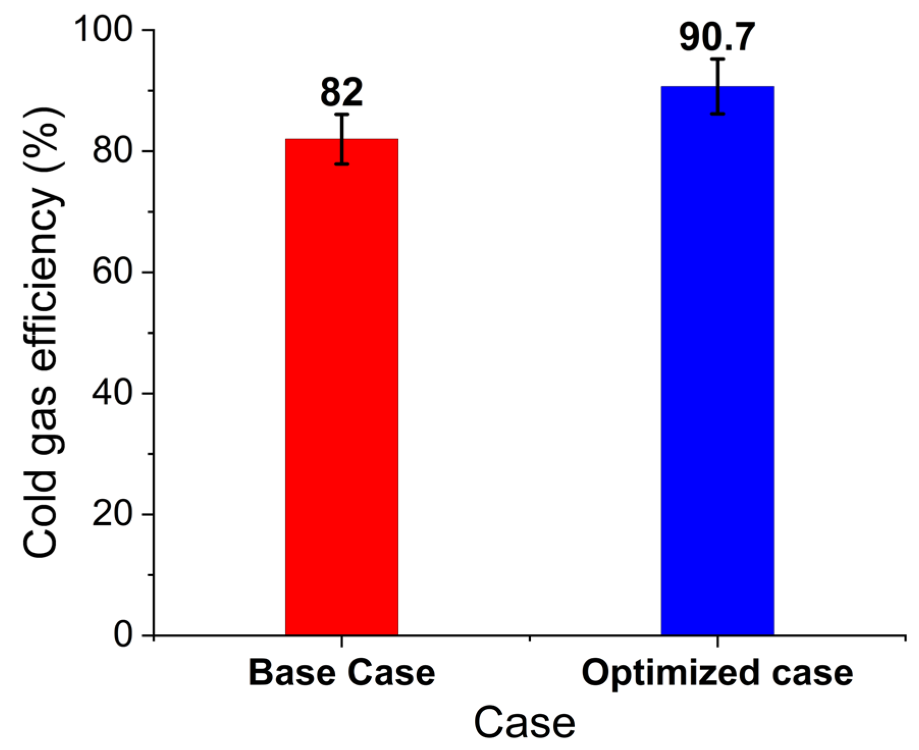
A comparison between the base case and optimized case was performed to assess the effectiveness of the optimized strategy. As shown in Figure 10, the optimization process increased the CGE from 82.0% in the base case to 90.6% in the optimized case, representing an improvement of 8.6%. The enhancement in CGE is accompanied by a reduction in specific torch power from 1664 kJ/kg to 1262 kJ/kg, along with an increase in the air-to-feed mass flow ratio from 1.37 to 1.81. Similarly, the optimized case exhibited a slightly lower syngas HHV compared to the base case; however, the CGE increased due to improved overall energy conversion efficiency within the gasification process. Since CGE depends not only on syngas HHV but also on the relationship between useful syngas energy output and total energy input, the optimized operating conditions reduced unnecessary energy consumption and improved thermodynamic utilization efficiency. These changes demonstrate that the optimized process not only improves energy efficiency but also reduces the electrical energy demand of the plasma torch. However, the air flow rate was increased, which enhances the combustion reaction for the complete conversion of carbon into gaseous species, resulting in an increase in HHV followed by an increase in CGE.
The obtained results are consistent with findings reported in previous studies on plasma gasification of municipal solid waste, as shown in Table 9. Similar to the observations of Nemmour et al. [58], an increase in plasma torch power enhanced the production of H2 and CO due to intensified endothermic reforming reactions, leading to improved syngas quality and CGE. Their study reported a maximum CGE of 57.64% under optimized operating conditions using Aspen Plus and response surface methodology. In contrast, the present work achieved a significantly higher optimized CGE of 90.6% using an ANN–GA optimization framework integrated with Aspen Plus simulation. Furthermore, the observed decrease in syngas heating value at higher air-to-feed ratios agrees with the findings of Zhang et al. [39], who reported that increasing equivalence ratio enhances oxidation reactions and reduces syngas heating value during plasma gasification of MSW. The trends obtained in this study also align with the Aspen Plus simulation work of Niu et al. [59], who demonstrated that higher gasification temperatures favor H2 and CO formation and improve gasification efficiency. These comparisons validate the reliability of the developed simulation and optimization framework while demonstrating its improved performance for Lahore-specific MSW.

4. Conclusions

In this study, a detailed simulation of an updraft plasma gasification plant was performed, and the influence of key operating parameters on system performance was evaluated through sensitivity analysis. Furthermore, an optimization step was implemented to maximize the CGE of the gasification process. Based on the comprehensive parametric and optimization analyses, the following conclusions can be drawn:
  • An increase in specific torch power results in a higher HTZ temperature within the gasifier. This enhances endothermic reactions such as methane steam reforming, carbon–steam reforming, and the Boudouard reaction, leading to increased molar fractions of H2 and CO in the synthesis gas. Consequently, the HHV of syngas increases with specific torch power up to 586 kJ/kg, beyond which no significant improvement was observed. The CGE initially increases and reaches a maximum at 586 kJ/kg; however, further increases in torch power reduce CGE due to the absence of additional gains in syngas HHV despite higher energy input.
  • Increasing the air-to-feed mass flow ratio raises the HTZ temperature due to enhanced exothermic oxidation reactions caused by higher oxygen availability. This results in a reduction in the molar composition of H2 and CO, accompanied by an increase in CO2 formation, thereby lowering the HHV of syngas. At a low air-to-feed flow rate, the higher syngas HHV leads to an initial increase in CGE, with a maximum value observed at an air-to-feed ratio of 2.62. Beyond this point, excessive oxidation significantly reduces the HHV of syngas, causing a decline in CGE.
  • Optimization using the ANN–GA integrated framework yielded a maximum CGE of 90.6% within the selected operating range. The corresponding optimal operating conditions were an MSW feed rate of 219 kg/h, an air-to-feed mass flow ratio of 1.81, and a specific torch power of 1262.4 kJ/kg. When these optimized parameters were implemented in the Aspen Plus® simulation model, a CGE of 90.7% was obtained. The relative error between the optimized and simulated results was only 0.11%, demonstrating excellent agreement and validating the robustness and reliability of the proposed optimization framework.
The present study demonstrates the successful integration of Aspen Plus® simulation with an ANN–GA optimization framework for improving the performance of an updraft plasma gasification system using Lahore-specific MSW. The novelty of this work lies in the development of a region-specific plasma gasification model based on the composition of Lahore’s MSW and the application of surrogate-based ANN–GA optimization to maximize CGE. Unlike previous studies that primarily focused on conventional simulation approaches, the proposed framework combines detailed thermodynamic modeling with intelligent optimization techniques to achieve enhanced gasification performance.
The findings of this research provide a strong foundation for future investigations involving experimental validation of the developed model, techno-economic assessment, life cycle analysis, and scale-up of plasma gasification systems for industrial applications. The developed modeling and optimization framework can be extended to other MSW compositions and operational conditions with appropriate feedstock characterization and model adjustment. Future studies may also explore alternative plasma gases, advanced syngas cleaning systems, hydrogen-rich syngas production, and integration with carbon capture technologies to further improve the environmental and energetic performance of waste-to-energy systems.


Author Contributions

Conceptualization, H.A. and A.A.; methodology, H.A. and R.K.; software, H.A., K.R. and A.O.; validation, K.R., A.O. and R.K.; formal analysis, W.W.K. and F.M.A.-K.; investigation, H.A. and A.A.; resources, K.R. and R.K.; data curation, H.A., A.A. and A.O.; writing—original draft preparation, H.A. and A.A.; writing—review and editing, K.R., A.O., R.K., W.W.K. and F.M.A.-K.; visualization, H.A., A.O. and W.W.K.; supervision, K.R. and R.K. All authors have read and agreed to the published version of the manuscript.

Funding

This research received no external funding.

Data Availability Statement

The data supporting the findings of this study, including MATLAB code, Aspen Plus simulation files, and Excel data sheets, are available from the corresponding author upon reasonable request.

Acknowledgments

The authors sincerely acknowledge the support of the Experiment and Diagnostic Division, Pakistan Tokamak Plasma Research Institute, and the Department of Chemical Engineering, Pakistan Institute of Engineering and Applied Sciences. The authors also gratefully recognize the support provided by the Interdisciplinary Research Center for Refining and Advanced Chemicals (IRC-RAC) at King Fahd University of Petroleum and Minerals (KFUPM). In preparing this manuscript, the authors did not use generative artificial intelligence (AI) or AI-assisted technologies for the development of scientific content, data analysis, interpretation, or conclusions. AI-based tools were employed only for language editing, grammatical correction, and enhancing clarity. All scientific content was developed, critically reviewed, and verified by the authors, who take full responsibility for the accuracy, integrity, and originality of the work.

Conflicts of Interest

The authors declare no conflicts of interest.

References

  1. Maalouf, A.; Mavropoulos, A. Re-Assessing Global Municipal Solid Waste Generation. Waste Manag. Res. 2023, 41, 936–947. [Google Scholar] [CrossRef] [Scilit] [PubMed]
  2. Mahar, A.; Naseem Malik, R.; Qadir, A.; Ahmed, T.; Khan, Z.; Ali Khan, M. Review and Analysis of Current Solid Waste Management Situation in Urban Areas of Pakistan. In Proceedings of the International Conference on Sustainable Solid Waste Management, Chennai, India, 5–7 September 2007; pp. 34–41. [Google Scholar]
  3. Sharma, K.D.; Jain, S. Municipal Solid Waste Generation, Composition, and Management: The Global Scenario. Soc. Responsib. J. 2020, 16, 917–948. [Google Scholar] [CrossRef] [Scilit]
  4. Mol, M.P.G.; Zolnikov, T.R.; Neves, A.C.; dos Santos, G.R.; Tolentino, J.L.L.; de Vasconcelos Barros, R.T.; Heller, L. Healthcare Waste Generation in Hospitals per Continent: A Systematic Review. Environ. Sci. Pollut. Res. 2022, 29, 42466–42475. [Google Scholar] [CrossRef] [Scilit] [PubMed]
  5. Nadeem, K.; Shahzad, S.; Hassan, A.; Usman Younus, M.; Asad Ali Gillani, S.; Farhan, K. Municipal Solid Waste Generation and Its Compositional Assessment for Efficient and Sustainable Infrastructure Planning in an Intermediate City of Pakistan. Environ. Technol. 2023, 44, 3196–3214. [Google Scholar] [CrossRef] [Scilit] [PubMed]
  6. Nadeem, K.; Farhan, K.; Ilyas, H. Waste Amount Survey and Physio-Chemical Analysis of Municipal Solid Waste Generated in Gujranwala-Pakistan. Int. J. Waste Resour. 2016, 6, 1000196. [Google Scholar] [CrossRef]
  7. Korai, M.S.; Mahar, R.B.; Uqaili, M.A. The Feasibility of Municipal Solid Waste for Energy Generation and Its Existing Management Practices in Pakistan. Renew. Sustain. Energy Rev. 2017, 72, 338–353. [Google Scholar] [CrossRef] [Scilit]
  8. Akhund, M.A.; Memon, A.H.; Memon, N.A.; Ali, T.H.; Khos, A.R.; Imad, H.U. Exploring Types of Waste Generated: A Study of Construction Industry of Pakistan; Penerbit Universiti Kebangsaan Malaysia: Bangi, Malaysia, 2019. Available online: http://neuseal.mod.gov.my/neuseal/Record/ukm-13672 (accessed on 14 October 2024).
  9. Arub, S.; Ahmad, S.R.; Ashraf, S.; Majid, Z.; Rahat, S.; Paracha, R.I. Assessment of Waste Generation Rate in Teaching Hospitals of Metropolitan City of Pakistan. Civ. Eng. J. 2020, 6, 1809–1821. [Google Scholar] [CrossRef] [Scilit]
  10. Ilyas, H.; Ilyas, S.; Rashid Ahmad, S.; Nawaz Ch, M. Waste Generation Rate and Composition Analysis of Solid Waste in Gujranwala City Pakistan. Int. J. Waste Resour. 2017, 7, 1000297. [Google Scholar] [CrossRef]
  11. Jadoon, A.; Batool, S.A.; Chaudhry, M.N. Assessment of Factors Affecting Household Solid Waste Generation and Its Composition in Gulberg Town, Lahore, Pakistan. J. Mater. Cycles Waste Manag. 2014, 16, 73–81. [Google Scholar] [CrossRef] [Scilit]
  12. Arshad, H.; Qasim, M.; Thaheem, M.J.; Gabriel, H.F. Quantification of Material Wastage in Construction Industry of Pakistan: An Analytical Relationship between Building Types and Waste Generation. J. Constr. Dev. Ctries. 2017, 22, 19–34. [Google Scholar] [CrossRef] [Scilit]
  13. Jabeen, F.; Adrees, M.; Ibrahim, M.; Mahmood, A.; Khalid, S.; Sipra, H.F.K.; Bokhari, A.; Mubashir, M.; Khoo, K.S.; Show, P.L. Trash to Energy: A Measure for the Energy Potential of Combustible Content of Domestic Solid Waste Generated from an Industrialized City of Pakistan. J. Taiwan Inst. Chem. Eng. 2022, 137, 104223. [Google Scholar] [CrossRef] [Scilit]
  14. Javied, S.; Hanan, F.; Munawar, S.; Qasim, M.; Saqib Anees, M.; Usman Ghani, M.; Azad, A.; Khalid, M.; Ullah, I.; Ansar, A. Management of Municipal Solid Waste Generated in Eight Cities of Pakistan. Int. J. Sci. Eng. Res. 2014, 5, 1186–1192. [Google Scholar]
  15. Couto, N.D.; Silva, V.B.; Rouboa, A. Thermodynamic Evaluation of Portuguese Municipal Solid Waste Gasification. J. Clean. Prod. 2016, 139, 622–635. [Google Scholar] [CrossRef] [Scilit]
  16. Mir, K.A.; Purohit, P.; Mehmood, S. Sectoral Assessment of Greenhouse Gas Emissions in Pakistan. Environ. Sci. Pollut. Res. 2017, 24, 27345–27355. [Google Scholar] [CrossRef] [Scilit] [PubMed]
  17. Malik, W.; Shahid, H.; Zafar, R.; Uddin, Z.; Wazir, Z.; Anwar, Z.; Khattak, J.Z.K.; Ali, S.S. Role of Pakistan in Global Climate Change through Greenhouse Gas Emissions (GHGs). Res. J. Environ. Earth Sci. 2012, 4, 996–1001. [Google Scholar]
  18. Hussain, M.; Butt, A.R.; Uzma, F.; Ahmed, R.; Islam, T.; Yousaf, B. A Comprehensive Review of Sectorial Contribution towards Greenhouse Gas Emissions and Progress in Carbon Capture and Storage in Pakistan. Greenh. Gases Sci. Technol. 2019, 9, 617–636. [Google Scholar] [CrossRef] [Scilit]
  19. Bentley, T.G.K.; Effros, R.M.; Palar, K.; Keeler, E.B. Waste in the U.S. Health Care System: A Conceptual Framework. Milbank Q. 2008, 86, 629–659. [Google Scholar] [CrossRef] [Scilit] [PubMed]
  20. Wang, Y.; Yan, Y.; Chen, G.; Zuo, J.; Yan, B.; Yin, P. Effectiveness of Waste-to-Energy Approaches in China: From the Perspective of Greenhouse Gas Emission Reduction. J. Clean. Prod. 2017, 163, 99–105. [Google Scholar] [CrossRef] [Scilit]
  21. Zaman, A.U. Comparative Study of Municipal Solid Waste Treatment Technologies Using Life Cycle Assessment Method. Int. J. Environ. Sci. Technol. 2010, 7, 225–234. [Google Scholar] [CrossRef] [Scilit]
  22. Cucchiella, F.; D’Adamo, I.; Gastaldi, M. Sustainable Waste Management: Waste to Energy Plant as an Alternative to Landfill. Energy Convers. Manag. 2017, 131, 18–31. [Google Scholar] [CrossRef] [Scilit]
  23. Alzate-Arias, S.; Jaramillo-Duque, Á.; Villada, F.; Restrepo-Cuestas, B. Assessment of Government Incentives for Energy Fromwaste in Colombia. Sustainability 2018, 10, 1294. [Google Scholar] [CrossRef] [Scilit]
  24. Oliveira, M.; Ramos, A.; Ismail, T.M.; Monteiro, E.; Rouboa, A. A Review on Plasma Gasification of Solid Residues: Recent Advances and Developments. Energies 2022, 15, 1475. [Google Scholar] [CrossRef] [Scilit]
  25. Male, K. Small Scale Plasma Gasification of Municipal Solid Waste. Master’s Thesis, Portland State University, Portland, OR, USA, 2021. [Google Scholar] [CrossRef] [Scilit]
  26. Phillips, J. Different Types of Gasifiers and Their Integration with Gas Turbines. In The Gasifipedia Handbook; US Dept. of Energy National Energy Technology Laboratory: Morgantown, WV, USA, 2006. Available online: https://www.netl.doe.gov/sites/default/files/netl-file/1-2-1.pdf (accessed on 22 May 2024).
  27. Sikandar Yusufoddin, M. CFD Modeling of Plasma Thermal Reactor for Waste Treatment. Master’s Thesis, Purdue University, West Lafayette, IN, USA, 2009; p. 1470160. [Google Scholar]
  28. Mountouris, A.; Voutsas, E.; Tassios, D. Solid Waste Plasma Gasification: Equilibrium Model Development and Exergy Analysis. Energy Convers. Manag. 2006, 47, 1723–1737. [Google Scholar] [CrossRef] [Scilit]
  29. Kumar, A.; Samadder, S.R. A Review on Technological Options of Waste to Energy for Effective Management of Municipal Solid Waste. Waste Manag. 2017, 69, 407–422. [Google Scholar] [CrossRef] [Scilit] [PubMed]
  30. Castaldi, M.; van Deventer, J.; Lavoie, J.M.; Legrand, J.; Nzihou, A.; Pontikes, Y.; Py, X.; Vandecasteele, C.; Vasudevan, P.T.; Verstraete, W. Progress and Prospects in the Field of Biomass and Waste to Energy and Added-Value Materials. Waste Biomass Valorization 2017, 8, 1875–1884. [Google Scholar] [CrossRef] [Scilit]
  31. Sharma, D.; Mistry, A.; Palanichamy, V.M.; Sanghariyat, A.; Mistry, H.; Chaudhuri, P.; Chaturvedi, S.; Nema, S.K. Design and Analysis of a Plasma Chamber for Thermal Processing Applications. Plasma Fusion Res. 2022, 17, 2406051. [Google Scholar] [CrossRef] [Scilit]
  32. Salonitis, K.; Vatousianos, S. Experimental Investigation of the Plasma Arc Cutting Process. Procedia CIRP 2012, 3, 287–292. [Google Scholar] [CrossRef] [Scilit]
  33. Bhabha Atomic Research Centre. Air Plasma Incinerator. Available online: https://barc.gov.in/technologies/air_plasma/ (accessed on 27 May 2024).
  34. Minutillo, M.; Perna, A.; Di Bona, D. Modelling and Performance Analysis of an Integrated Plasma Gasification Combined Cycle (IPGCC) Power Plant. Energy Convers. Manag. 2009, 50, 2837–2842. [Google Scholar] [CrossRef] [Scilit]
  35. Sanlisoy, A.; Carpinlioglu, M.O. A Review on Plasma Gasification for Solid Waste Disposal. Int. J. Hydrogen Energy 2017, 42, 1361–1365. [Google Scholar] [CrossRef] [Scilit]
  36. Agon, N.; Hrabovský, M.; Chumak, O.; Hlína, M.; Kopecký, V.; Mašláni, A.; Bosmans, A.; Helsen, L.; Skoblja, S.; Van Oost, G.; et al. Plasma Gasification of Refuse Derived Fuel in a Single-Stage System Using Different Gasifying Agents. Waste Manag. 2016, 47, 246–255. [Google Scholar] [CrossRef] [Scilit] [PubMed]
  37. Malkow, T. Novel and Innovative Pyrolysis and Gasification Technologies for Energy Efficient and Environmentally Sound MSW Disposal. Waste Manag. 2004, 24, 53–79. [Google Scholar] [CrossRef] [Scilit] [PubMed]
  38. Khuriati, A.; Purwanto, P.; Setiyo Huboyo, H.; Suryono, S.; Bawono Putro, A. Application of aspen plus for municipal solid waste plasma gasification simulation: Case study of Jatibarang Landfill in Semarang Indonesia. J. Phys. Conf. Ser. 2018, 1025, 012006. [Google Scholar] [CrossRef] [Scilit]
  39. Zhang, Q.; Dor, L.; Fenigshtein, D.; Yang, W.; Blasiak, W. Gasification of Municipal Solid Waste in the Plasma Gasification Melting Process. Appl. Energy 2012, 90, 106–112. [Google Scholar] [CrossRef] [Scilit]
  40. Okati, A.; Reza Khani, M.; Shokri, B.; Rouboa, A.; Monteiro, E. Optimizing the Operating Conditions for Hydrogen-Rich Syngas Production in a Plasma Co-Gasification Process of Municipal Solid Waste and Coal Using Aspen Plus. Int. J. Hydrogen Energy 2022, 47, 26891–26900. [Google Scholar] [CrossRef] [Scilit]
  41. Montiel-Bohórquez, N.D.; Saldarriaga-Loaiza, J.D.; Pérez, J.F. A Techno-Economic Assessment of Syngas Production by Plasma Gasification of Municipal Solid Waste as a Substitute Gaseous Fuel. J. Energy Resour. Technol. Trans. 2021, 143, 090901. [Google Scholar] [CrossRef] [Scilit]
  42. Azam, M.; Jahromy, S.S.; Raza, W.; Raza, N.; Lee, S.S.; Kim, K.-H.; Winter, F. Status, Characterization, and Potential Utilization of Municipal Solid Waste as Renewable Energy Source: Lahore Case Study in Pakistan. Environ. Int. 2020, 134, 105291. [Google Scholar] [CrossRef] [Scilit] [PubMed]
  43. Janajreh, I.; Raza, S.S.; Valmundsson, A.S. Plasma Gasification Process: Modeling, Simulation and Comparison with Conventional Air Gasification. Energy Convers. Manag. 2013, 65, 801–809. [Google Scholar] [CrossRef] [Scilit]
  44. Gagliano, A.; Nocera, F.; Bruno, M.; Cardillo, G. Development of an Equilibrium-Based Model of Gasification of Biomass by Aspen Plus. Energy Procedia 2017, 111, 1010–1019. [Google Scholar] [CrossRef] [Scilit]
  45. Indrawan, N.; Mohammad, S.; Kumar, A.; Huhnke, R.L. Modeling Low Temperature Plasma Gasification of Municipal Solid Waste. Environ. Technol. Innov. 2019, 15, 100412. [Google Scholar] [CrossRef] [Scilit]
  46. Mazzoni, L.; Ahmed, R.; Janajreh, I. Plasma Gasification of Two Waste Streams: Municipal Solid Waste and Hazardous Waste from the Oil and Gas Industry. Energy Procedia 2017, 105, 4159–4166. [Google Scholar] [CrossRef] [Scilit]
  47. Perna, A.; Minutillo, M.; Jannelli, E. Hydrogen from Intermittent Renewable Energy Sources as Gasification Medium in Integrated Waste Gasification Combined Cycle Power Plants: A Performance Comparison. Energy 2016, 94, 457–465. [Google Scholar] [CrossRef] [Scilit]
  48. Galeno, G.; Minutillo, M.; Perna, A. From Waste to Electricity through Integrated Plasma Gasification/Fuel Cell (IPGFC) System. Int. J. Hydrogen Energy 2011, 36, 1692–1701. [Google Scholar] [CrossRef] [Scilit]
  49. Barrera, R.; Salazar, C.; Pérez, J.F. Thermochemical Equilibrium Model of Synthetic Natural Gas Production from Coal Gasification Using Aspen Plus. Int. J. Chem. Eng. 2014, 192057. [Google Scholar] [CrossRef] [Scilit]
  50. Cengel, Y.A.; Boles, M.A. Introduction and Basic Concepts. In Thermodynamics: An Engineering Approach, 8th ed.; McGraw-Hill: New York, NY, USA, 2015. [Google Scholar]
  51. Ozdinc Carpinlioglu, M.; Sanlisoy, A. Performance Assessment of Plasma Gasification for Waste to Energy Conversion: A Methodology for Thermodynamic Analysis. Int. J. Hydrogen Energy 2018, 43, 11493–11504. [Google Scholar] [CrossRef] [Scilit]
  52. Hyun, A. Plasma Torches by Westinghouse Plasma Corporation. Available online: https://www.academia.edu/24044626/Plasma_Torches_by_Westinghouse_Plasma_Corporation (accessed on 20 October 2024).
  53. Ibrahim, D.; Jobson, M.; Li, J.; Guillén-Gosálbez, G. Optimization-Based Design of Crude Oil Distillation Units Using Surrogate Column Models and a Support Vector Machine. Chem. Eng. Res. Des. 2018, 134, 212–225. [Google Scholar] [CrossRef] [Scilit]
  54. Mehrotra, K.; Mohan, C.; Ranka, S. Elements of Artificial Neural Networks; MIT Press: Cambridge, MA, USA, 1996. [Google Scholar] [CrossRef]
  55. Comito, C.; Pizzuti, C. Artificial Intelligence for Forecasting and Diagnosing COVID-19 Pandemic: A Focused Review. Artif. Intell. Med. 2022, 128, 102286. [Google Scholar] [CrossRef] [Scilit] [PubMed]
  56. Fonseca, L.L.; Böttcher, L.; Mehrad, B.; Laubenbacher, R.C. Optimal Control of Agent-Based Models via Surrogate Modeling. PLoS Comput. Biol. 2025, 21, e1012138. [Google Scholar] [CrossRef] [Scilit] [PubMed]
  57. Gambella, C.; Ghaddar, B.; Naoum-Sawaya, J. Optimization Problems for Machine Learning: A Survey. Eur. J. Oper. Res. 2021, 290, 807–828. [Google Scholar] [CrossRef] [Scilit]
  58. Nemmour, A.; Inayat, A.; Janajreh, I.; Ghenai, C. Syngas production from municipal solid waste plasma gasification: A simulation and optimization study. Fuel 2023, 349, 128698. [Google Scholar] [CrossRef] [Scilit]
  59. Niu, M.; Huang, Y.; Jin, B.; Wang, X. Simulation of Syngas Production from Municipal Solid Waste Gasification in a Bubbling Fluidized Bed Using Aspen Plus. Ind. Eng. Chem. Res. 2013, 52, 14768–14775. [Google Scholar] [CrossRef] [Scilit]
Figure 1. Flowsheet of updraft plasma gasification model.
Chemengineering 10 00077 g001
Figure 2. Schematic of updraft plasma gasification model.
Chemengineering 10 00077 g002
Figure 3. Assessment of surrogate models founded on (a) R2 and (b) RMSE for mass flowrate of slag.
Chemengineering 10 00077 g003
Figure 4. Assessment of surrogate models founded on (a) R2 and (b) RMSE for HHV of syngas.
Chemengineering 10 00077 g004
Figure 5. Flowchart of the ANN-GA-based optimization framework.
Chemengineering 10 00077 g005
Figure 6. Influence of specific torch power on molar fraction of syngas.
Chemengineering 10 00077 g006
Figure 7. Influence of specific torch power on (a) HHV of syngas and (b) cold gas efficiency.
Chemengineering 10 00077 g007
Figure 8. Influence of air-to-feed ratio on molar fraction of syngas.
Chemengineering 10 00077 g008
Figure 9. Influence of air-to-feed ratio on (a) HHV of syngas and (b) cold gas efficiency.
Chemengineering 10 00077 g009
Figure 10. Impact of optimization on CGE of an updraft gasifier.
Chemengineering 10 00077 g010
Table 1. Composition of Lahore MSW [42].
Ultimate CompositionWeight % Dry Basis
Carbon63.91
Hydrogen8.19
Nitrogen0.4
Sulfur0.1
Oxygen27.4
Proximate CompositionWeight % Dry Basis
Fixed carbon7.6
Volatile matter79.8
Ash9.3
Moisture percent3.3
HHV (kJ/kg)22,570
Table 2. Operating parameters of the plasma gasifier model (base case).
ParametersValue
Feed mass flow rate250 kg/h
Air mass flow rate343 kg/h
Air-to-feed mass ratio1.375
Torch pressure6 Bar
Electrical torch power144.5 kW
Torch efficiency80%
Effective (thermal) torch power116 kW
Specific torch power1665 kJ/kg
Torch temperature1363.5 °C
HTZ temperature2000 °C
LTZ temperature1800 °C
Table 3. Data range of input variables.
Input ParametersData Range
Mass rate of MSW200–800 kg/h
Air-to-feed ratio0–2
Specific torch power180–8640 kJ/kg
Table 4. Specification of developed ANN model.
ParametersValue
% of numerals utilized for training of model70
% of numerals utilized for validation of model15
% of numerals utilized for testing of model15
No. of hidden neurons used for mslag10
No. of hidden neurons used for HHVsyn10
Optimizer used for trainingLevenberg–Marquardt
Table 5. Mole fraction of the syngas stream.
ComponentPlasma Gas (Air) Mole Fraction (%)
Hydrogen32.62
Nitrogen34.97
Oxygen1.57 × 10−13
CO30.77
CO22.52 × 10−4
Carbon0
Sulfur0
CH40.001
Water1.62
H2S0.024
COS0.001
Table 6. Results of the syngas stream.
ComponentPlasma Gas (Air) Value
HHV (kJ/kg)9353.9
LHV (kJ/kg)8568.2
Feed mass flowrate (kg/h)250
Syngas flowrate (kg/h)532
Air flowrate (kg/h)344
Effective torch power (kW)116
Cold gas efficiency82.0%
Table 7. Results of optimization.
Optimized Input Parameters
Mass flow rate of MSW219.24 kg/h
Air-to-feed-ratio1.81
Specific torch power1262.4 kJ/kg
Optimized Cold Gas Efficiency
CGE90.6%
Table 8. Outcomes of validation with simulation model.
Validated Results
Mass flowrate of MSW219.24 kg/h
Air flowrate397 kg/h
Torch electrical power96 kW
Effective (thermal) torch power77 kW
Air-to-feed ratio1.81
Specific torch power1262.4 kJ/kg
HHV of syngas8200.7 kJ/kg
Mass flowrate of syngas578 kg/h
Mass flowrate of slag38 kg/h
Plasma (Torch) temperature830.8 °C
HTZ temperature1894 °C
Optimized CGE90.6%
Calculated CGE90.7%
Relative error0.11%
Table 9. Comparison of present study with previous research.
StudyMSW
Region
MethodologyKey FindingsMaximum CGE
Nemmour et al. (2023) [58]UAE MSWAspen Plus + Response Surface Methodology (RSM)Increased plasma power enhanced H2 and CO production and improved syngas quality57.64%
Zhang et al. (2012) [39]Israel MSWPlasma Gasification ExperimentalHigher equivalence ratio increased oxidation reactions and reduced syngas calorific value60%
Niu et al. (2013) [59]China MSWAspen Plus SimulationHigher gasification temperature promoted H2 and CO formation and improved gasification efficiency87.6%
Present StudyLahore, Pakistan MSWAspen Plus + ANN–GA OptimizationOptimized plasma gasification model with improved syngas quality and enhanced thermal performance90.6%
Disclaimer/Publisher’s Note: The statements, opinions and data contained in all publications are solely those of the individual author(s) and contributor(s) and not of MDPI and/or the editor(s). MDPI and/or the editor(s) disclaim responsibility for any injury to people or property resulting from any ideas, methods, instructions or products referred to in the content.