Article

Prototypes of Highly Effective Stress Balancing AlN Interlayers in MOVPE GaN-on-Si (111)

1
College of Integrated Circuits and Optoelectronic Chips, Shenzhen Technology University, Shenzhen 518118, China
2
Research Center for Advanced Science and Technology, The University of Tokyo, Tokyo 153-8904, Japan
3
Institute of Engineering Innovation, School of Engineering, The University of Tokyo, Tokyo 113-8656, Japan
4
Department of Electrical Engineering & Information System, School of Engineering, The University of Tokyo, Tokyo 113-8656, Japan
*
Author to whom correspondence should be addressed.
These authors contributed equally to this work.
Inorganics 2025, 13(9), 302; https://doi.org/10.3390/inorganics13090302
Submission received: 31 July 2025 / Revised: 29 August 2025 / Accepted: 1 September 2025 / Published: 7 September 2025
(This article belongs to the Special Issue Advances in Calcium-Ion Batteries)

Abstract

The GaN-on-Si virtual substrate is now an indispensable platform for the application of GaN in the fields of power devices, radio frequency, light-emitting devices, etc. Such applications are still in need of more effective stress balancing techniques to achieve higher quality and stress balance in GaN-on-Si at a lower thickness. In this study, three promising practical prototypes of highly effective stress-balancing structures are proposed to realize the concept of an ideal AlN interlayer (AlN-IL) featuring a completely relaxed lower AlN/GaN interface and a fully strained upper GaN/AlN interface. The first is a single-layer AlN interlayer grown via precursor pulsed-injection (PI-AlN-IL). The second combines a low-temperature AlN (LT-AlN) underlayer with a PI-AlN-IL. The third integrates LT-AlN with a high-temperature AlN cap. Compared with optimal conventional single-layer AlN interlayer references, all these designs more effectively induced compressive stress and strain in overlying GaN layers. This study opens new technical paths to balancing stress in GaN-on-Si systems at a reduced thickness more efficiently.

1. Introduction

Gallium nitride (GaN) epitaxy on silicon (Si) substrates represents a transformative approach in semiconductor technology, driven by the need for high-performance electronic and optoelectronic devices that leverage GaN’s superior material properties—including a wide bandgap (3.4 eV), high electron mobility, and critical electric field strength (3.3 MV/cm). These attributes allow GaN-based devices (e.g., high-electron-mobility transistors (HEMTs), lasers, and light-emitting diodes (LEDs)) to operate at higher frequencies, temperatures, and power densities than their silicon counterparts. The motivation for integrating GaN with Si substrates stems from Si’s cost-effectiveness, large wafer availability (up to 300 mm), compatibility with mature CMOS fabrication lines, and superior thermal conductivity compared to traditional substrates like sapphire or SiC. This integration opens the path toward monolithic co-integration of GaN power devices with Si logic circuits, enabling next-generation power electronics, RF amplifiers, and solid-state lighting [1,2,3].
The history of GaN-on-Si dates to the 1970s, but early efforts were hindered by severe challenges [4]. Firstly, lattice mismatch (~17%) between GaN and Si causes high-density threading dislocations (>109 cm−2). Secondly, thermal expansion coefficient mismatch (GaN: 5.6 × 10⁻⁶ K−1; Si: 2.6 × 10⁻⁶ K−1) induces tensile stress during cooling, leading to cracking in films thicker than ~1 μm. Moreover, chemical incompatibility, including Si meltback etching by Ga at high temperatures, degrades interface quality [5].
Breakthroughs in the 2000s, such as AlN nucleation layers and step-graded AlGaN buffers, enabled crack-free GaN growth. Dadgar et al. demonstrated that AlN interlayers (ILs) could compensate for tensile stress, paving the way for commercial adoption in LEDs and power devices [6]. Today, GaN-on-Si is commercially deployed in 200 mm wafers for high-voltage transistors and micro-LEDs, with ongoing research targeting 300 mm compatibility and improved reliability [1].
To mitigate the stress imbalance arising from lattice mismatch and thermal mismatch in a GaN-on-Si system, it is essential to introduce buffer layers (e.g., AlN or step-graded AlGaN) and interlayer structures [7,8,9,10,11]. In this work, we focused specifically on AlN interlayers. It was originally applied by Amano et al. for GaN growth on a sapphire substrate, where AlN interlayers were shown to improve GaN crystal quality [12]. Since then, AlN-ILs have been intensively investigated for the growth of GaN-on-Si [13,14,15]. The stress-balancing effect of the AlN interlayer is illustrated in Figure 1 by comparing wafer curvature evolution for GaN-on-Si samples grown with and without an AlN interlayer. Both samples had the same total GaN thickness of 1710 nm. During AlN buffer growth, the smaller AlN lattice constant ( a A l N ) compared with that of Si ( a A l N ) caused tensile stress in AlN, resulting in a concave wafer shape. In the subsequent GaN growth stage, as a A l N < a G a N , GaN was compressively stressed, leading to a convex wafer. For the sample without an AlN-IL, after cooling to room temperature (RT), due to the significant thermal expansion coefficient mismatch between GaN and Si, large tensile thermal stress was induced in the GaN layer. This caused the wafer curvature to increase sharply (concave) during cooling and led to the formation of microcracks. By contrast, in the sample with an AlN-IL, additional compressive stress that was introduced by the AlN-IL during the second GaN growth stage compensated for the tensile thermal stress upon cooling. As a result, the wafer curvature at RT was nearly zero (flat), and no cracks were observed. These results, seen in Figure 1, clearly demonstrated the strong stress-balancing role of AlN interlayers in GaN-on-Si heteroepitaxy.
To balance the tensile stress in GaN on Si and improve GaN crystal quality, several types of AlN-based interlayers have been employed. The first type was conventional single-layer AlN interlayers, which include low-temperature AlN (LT-AlN) and high-temperature AlN (HT-AlN) interlayers. LT-AlN, typically grown at 600–800 °C, introduces compressive stress through lattice mismatch and promotes V-pit formation, which bends threading dislocations (TDs). Jiang et al. demonstrated that LT-AlN interlayers grown at 800 °C reduced the TD density by up to 80% [16]. However, an overly thick LT-AlN (>30 nm) can cause surface roughening and incomplete GaN coalescence, degrading device performance [17]. HT-AlN interlayers, deposited at 900–1100 °C, generally yield superior crystallinity but also introduce high tensile strain, which often results in microcracks. Deura et al. showed that HT-AlN grown at 1050 °C under high V/III ratios (>5000) maintained flat interfaces and minimized strain relaxation [8]. A precise NH3 flow is critical in HT-AlN to suppress GaN decomposition at the interface; insufficient NH3 leads to voids and enhanced tensile stress [18]. The second type is composite interlayers, which include superlattice interlayers and functionally graded interlayers. AlN/GaN superlattice interlayers, composed of alternating ultrathin layers (e.g., 3 nm GaN/5 nm AlN), act as dislocation filters through strain-induced TD bending. Li et al. reported TD densities as low as 3.5 × 108 cm−2 using 25-period superlattice [19,20]. Alternatively, Al content in AlGaN interlayers can be linearly graded over a much greater thickness (~hundreds of nm) than typical interlayers, similar to step-graded AlGaN buffer layers. For example, Kei May Lau et al. used AlN/Al0.2Ga0.8N (10 nm/500 nm) composite interlayers that effectively compensated the tensile stress inside a GaN layer and reduced the TD density [21]. Liu et al. demonstrated that a thinner AlGaN interlayer (9–12 nm) improved GaN crystal quality but provided limited stress compensation [18]. In addition to AlN-based designs, SiNx interlayers have also been applied to the growth of GaN on Si. While they effectively reduce dislocation density, they do not contribute to stress balancing [11,22].
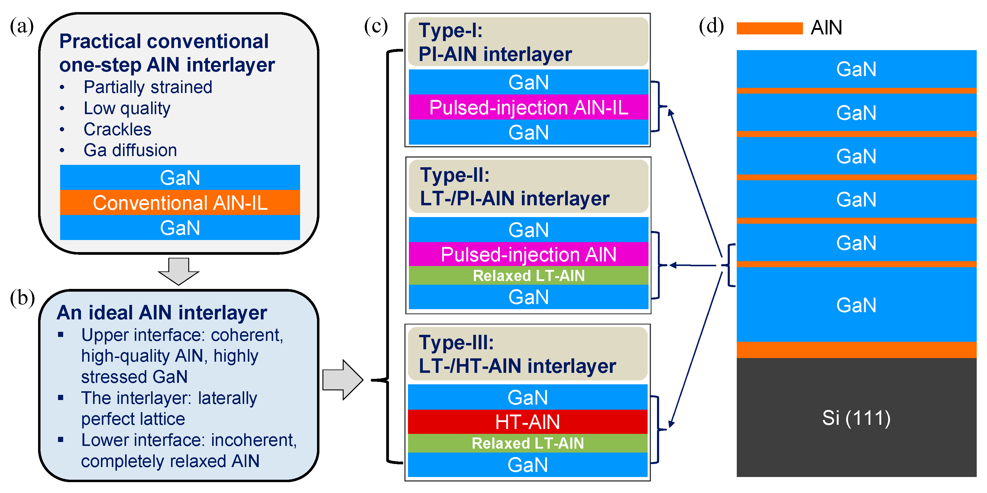
Despite extensive research on interlayers in the GaN-on-Si system, there remains a continuous search for innovative strategies to balance the stress that occurs in GaN-on-Si more efficiently and further enhance crystal quality, especially for high-performance applications such as HEMTs and radio frequency devices. In a previous study, we examined the growth conditions, stress balancing capabilities, micro-morphology, and the role of conventional single-layer AlN interlayers [23]. A proper conventional single-layer AlN interlayer was grown at a moderate temperature of around 900 °C, at a V/III ratio of 1500, with a thickness of approximately 9 nm, which induced about 1.2 GPa compressive stress in the overlying GaN layer. Through a comprehensive analysis of the AlN interlayer’s role, we proposed an ideal model: an AlN interlayer with the highest possible crystal quality, featuring a highly relaxed and laterally perfect lattice with a highly relaxed interface at the lower boundary and a highly strained interface at the upper boundary. Achieving such an ideal interlayer with a single-layer AlN is exceedingly challenging. To realize the “ideal interlayer” and maximize the compressive stress in the GaN layers, we proposed several prototypes of unconventional AlN interlayers, as illustrated in Figure 2. These include pulsed-injection AlN-ILs (PI-AlN-ILs, grown via a precursor pulsed-injection supply method), composite LT-/PI-AlN interlayers, and composite LT-/HT-AlN interlayers. On the capability of inducing compressive stress in GaN-on-Si, our results demonstrated that these unconventional prototype AlN-ILs have the potential to outperform traditional single-layer AlN interlayers.

2. Results and Discussion

2.1. Pulsed-Injection Precursor Supply Method Grown AlN Interlayers

Generally, it is challenging to grow high-quality AlN epitaxial films using MOVPE, primarily because of low aluminum adatom mobility and gas–phase reactions. Aluminum atoms exhibit low-surface migration at typical MOVPE temperatures (e.g., <1200 °C), hindering lateral growth and promoting 3D island formation instead of smooth films. Elevating the AlN growth temperature above 1400 °C improves adatom mobility and reduces defect density; however, such temperatures impose severe thermal loads on MOVPE reactor hardware and increase the risk of substrate or precursor decomposition. Consequently, strong gas–phase reactions between trimethylaluminum (TMAl) and ammonia (NH3) produce stable adducts that deplete reactive species and degrade crystal quality; these gas–phase pre-reactions are exacerbated at a higher T G [24]. To mitigate the gas–phase pre-reactions and thermal strain on the reactor hardware, researchers have explored low-temperature growth strategies. One promising approach is temporal separation of precursors (TMAl and NH3) by pulsed precursor injection with purge intervals, as illustrated in Figure 3. By injecting TMAl and NH3 in separate pulses and purging with hydrogen between them, the surface residence time available for Al adatom diffusion to incorporation sites is increased, promoting layer-by-layer growth and improving AlN film quality.
We previously developed a dedicated PI-AlN MOVPE process, where detailed growth conditions and procedures were given in reference [25]. In the previous work, we succeeded in growing high-quality AlN layers at 800 °C. The crystal quality and purity of 800 °C PI-AlN were comparable with those of AlN layers grown at 1240 °C by the conventional method. For a 520 nm thick PI-AlN film, X-ray diffraction full-width of half-maximum (FWHM) values for the AlN (0002) and AlN (10–12) planes were as low as 90 arcsec and 360 arcsec, respectively. H. Kroncke et al. likewise reported the effectiveness of the PI method at a T G of 1070 °C, obtaining similar crystal quality (density holes < 1 × 105 cm−2) comparable to conventional AlN grown at 1230 °C [26].
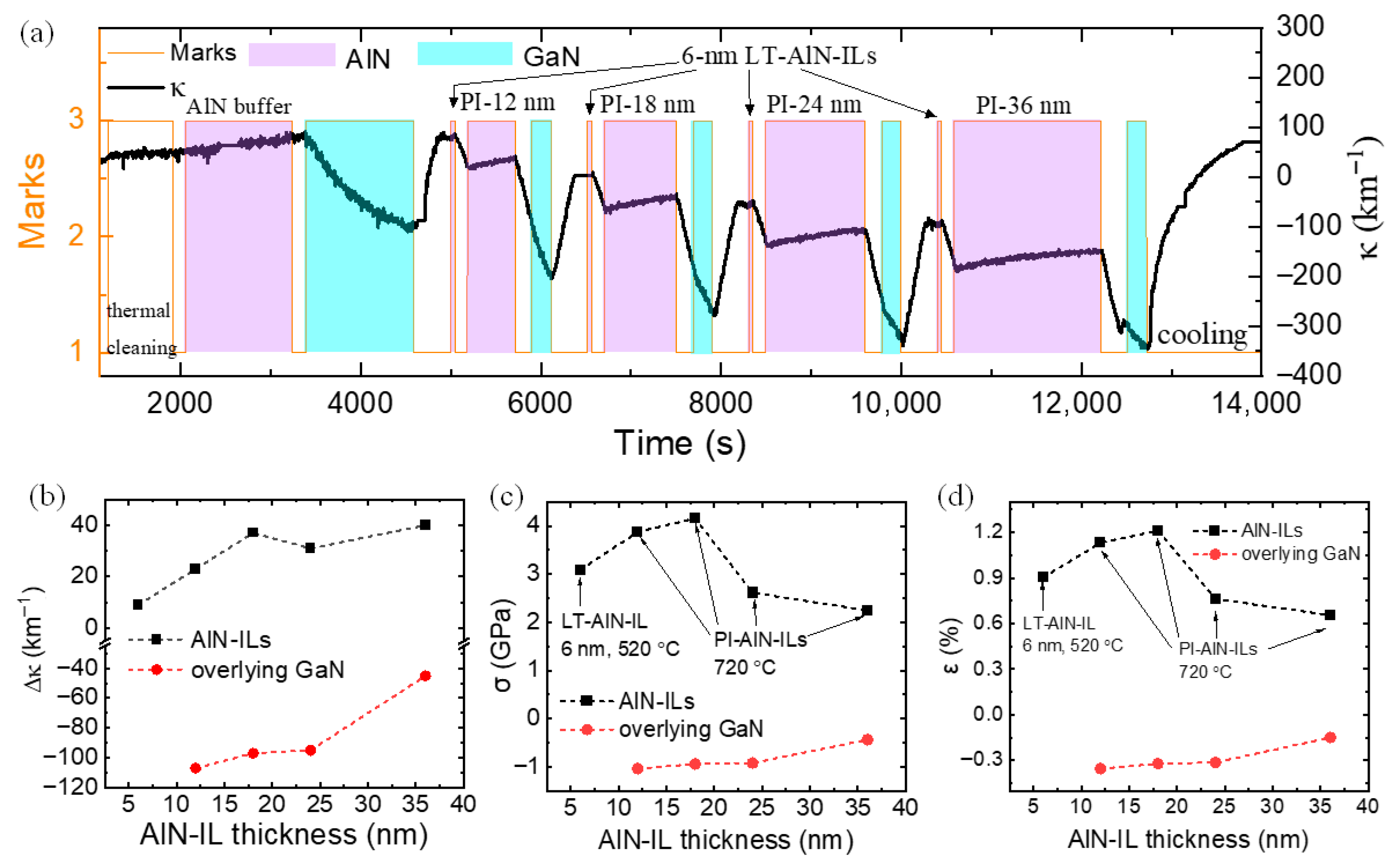
Since precursor pulsed-injection AlN-ILs can be grown at a low temperature (720 °C in this study) with high-quality, it may hold high-quality of both lower and upper interfaces. On the other hand, the lattice constant mismatch between the AlN interlayer and overlying GaN can be larger when the AlN interlayer is grown at a low T G . PI-AlN-ILs may be more efficient at stressing overlying GaN compressively due to these advantages. As the first trial, as plotted in Figure 3a, we first applied six layers of PI-AlN-ILs with thicknesses from 3 nm to 37 nm. The seventh AlN interlayer was grown via a conventional method at a temperature of 900 °C with a thickness of 9 nm. In Figure 3b, the curvature increments, both of the AlN interlayers and overlying GaN layers, were extracted from the curvature transition curve, as seen in Figure 3a. The stress in Figure 3c and strain in Figure 3d for both of the AlN interlayers and overlying GaN layers were calculated using the Stoney equation, based on the curvature increments in Figure 3b. For PI-AlN-ILs, it was mostly stressed with the largest tensile strain when it was 3 nm thick. With increasing PI-AlN thickness, the interlayer relaxed progressively: the interlayer stress decreased from 5.5 GPa to 1.5 GPa, and the strain decreased from 1.60% to 0.42%. It is reasonable that thinner epitaxial films are strained easily, particularly below the critical thickness. Larger strain in thin AlN-ILs reduces the lattice constant mismatch with the overlying GaN and, therefore, transfers less compressively stress to overlying GaN. As the PI-AlN-IL thickness was raised to 12 nm, the compressive stress and strain in the overlying GaN reached a maximum; further thickening to 25 nm and 37 nm, it stressed the overlying GaN less. This reduction is attributed to the enhanced relaxation of the PI-AlN-ILs via dislocation formation once it exceeded the critical thickness. The theoretical critical thickness of AlN on GaN at an elevated temperature (>1000 °C) is about 7.56 nm [27]. In addition to higher-density dislocations, crackles might have occurred for AlN-ILs thicker than the critical thickness [28], as observed by atomic force microscopy (AFM) and transmission electron microscopy (TEM) in a previous study on conventional AlN interlayers [23]. As marked in Figure 3a in the 37 nm thick PI-AlN-IL, a probable cracking initiation point was observed at a thickness of 24 nm, indicated by the curvature–transition slope falling to zero; a similar slop drop has been reported for thick conventional AlN-ILs [23]. The compressive stress and strain of overlying GaN on a 9 nm thick reference conventional AlN-IL were 0.52 GPa and 0.18%, which were much less than those on PI-AlN-ILs with a thickness > 10 nm.
In this sample, it was demonstrated that PI-AlN-ILs can be more efficient at compressively stressing overlying GaN. The growth conditions for the reference conventional AlN interlayer were the optimized conditions in the previous study [23]. Compared with the optimized conventional AlN-IL reference in this identical sample, the most efficient 12 nm PI-AlN-IL relaxed more with a smaller tensile stress and strain, and then elevated the compressive stress in the overlying GaN ( σ G a N ) from that on the reference AlN-IL (~0.60 GPa) to around 0.90 GPa on 12 nm thick PI-AlN, with an increment of about 50%. Consequently, compared with conventional AlN-ILs, PI-AlN-ILs might be closer to the concept of ideal AlN interlayer, as stated in Figure 2b.

2.2. LT-AlN/Pulsed-Injection AlN Interlayers

A limitation of PI-AlN-ILs is that the lower interface remains insufficiently relaxed, preventing a reduction in the lattice constant of AlN interlayers. To more closely approach the ideal AlN interlayer model, further relaxation of the lower interface of PI-AlN-ILs is required. One promising strategy is the insertion of an LT-AlN layer between underlying GaN and the PI-AlN-IL. AlN grown by MOVPE at low temperatures (<1000 °C) typically favors 3D island growth over layer-by-layer growth, which increases dislocation densities. Al-polar AlN tends to form etch pits, whereas N-polar AlN exhibits hexagonal hillocks [29]. Low T G results in rougher morphology and higher defect densities than high-temperature growth. This effect is particularly pronounced in thin AlN films (several to dozens of nanometers), where the limited thickness prevents complete coalescence [6]. Nevertheless, positioning it beneath PI-AlN-ILs can promote relaxation at the lower interface of the interlayer stack. Based on these considerations, we designed composite LT-/PI-AlN interlayers (sample B in Figure 4), which are expected to provide a more relaxed lower interface while preserving the high structural quality of the upper interface.
In sample B, the LT-AlN-IL part was grown at 520 °C with a V/III ratio of 1503 and a thickness of 6 nm. The thickness of the upper PI-AlN part varied from 12 nm to 36 nm, as noted in Figure 4. Consistent with the ideal AlN interlayer model, compared with 12 nm thick and 18 nm thick upper PI-AlN-ILs, the underlying 6 nm thick LT-AlN was much more relaxed. As the upper PI-AlN-IL thickness increased, the compressive stress and strain in the overlying GaN decreased. Compared with the highest compressive stress (−0.88 GPa) in overlying GaN on a 12 nm thick single PI-AlN-IL, that of the GaN on the first three thinner LT-/PI-AlN-ILs (PI-AlN thicknesses of 12, 18, and 24 nm) was higher (−1.04, −0.94, and −0.92 GPa, respectively). This result verified that the composite LT-/PI-AlN-ILs are more effective in stressing overlying GaN and are more efficient at stress balancing in GaN-on-Si. Thus, the composite LT-/PI-AlN structure more closely approached the concept of an ideal AlN interlayer.

2.3. LT/HT-AlN Interlayers

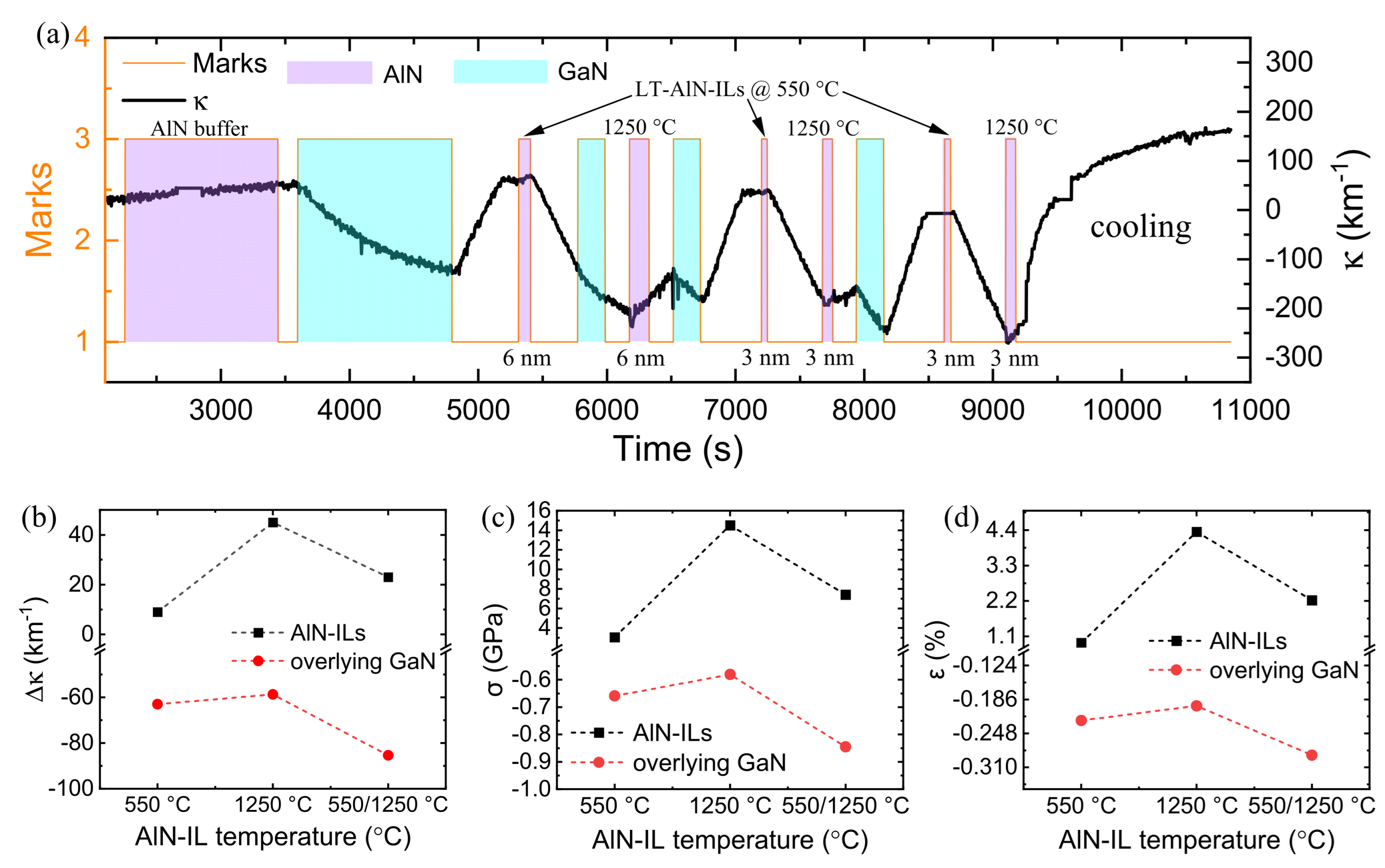
As noted above, high-temperature growth is a well-established strategy for achieving high-quality AlN. Therefore, combining a lower LT-AlN layer with an upper HT-AlN layer offers another pathway toward realizing the ideal AlN interlayer model. To evaluate this concept and assess the effectiveness of composite LT-/HT-AlN-ILs, sample C (Figure 5) was prepared with four configurations: a single LT-AlN interlayer, a single HT-AlN interlayer, a composite LT-/HT-AlN-IL (combining the two), and a duplicate of the composite structure without an overlying GaN layer for additional characterization (not discussed here). The results showed that the compressive stress and strain in overlying GaN on the composite LT-/HT-AlN-IL were about 50% higher than those in GaN on the former conventional single-layer AlN interlayers. At the same time, the tensile stress and strain in composite LT-/HT-AlN-IL were reduced by approximately half relative to the HT-AlN-IL case, indicating ~50% greater relaxation. These findings were fully consistent with the assumptions of the ideal AlN interlayer model: LT-AlN was more relaxed than HT-AlN, and a relaxed lower AlN/GaN interface and lower part of the interlayer leads to a smaller AlN interlayer lattice constant. In prior studies of conventional single-layer AlN interlayers, the HT-AlN-ILs suffered from significant Ga diffusion, leading to the unintentional formation of AlGaN. Since the lattice constant of AlGaN is larger than that of pure AlN, this effect reduced the compressive stress imposed on the overlying GaN. Therefore, another reason that the composite structure might enhance the performance of the two-step AlN IL was that Ga diffusion from the underlying GaN might have been stopped by the isolation of almost pure LT-AlN with a smaller lattice constant than AlGaN. Meanwhile, the high-quality HT-AlN cap maintained a coherent upper GaN/AlN interface, enabling stronger compressive stress in the overlying GaN. Together, these mechanisms provided a compelling demonstration of the ideal AlN interlayer concept.
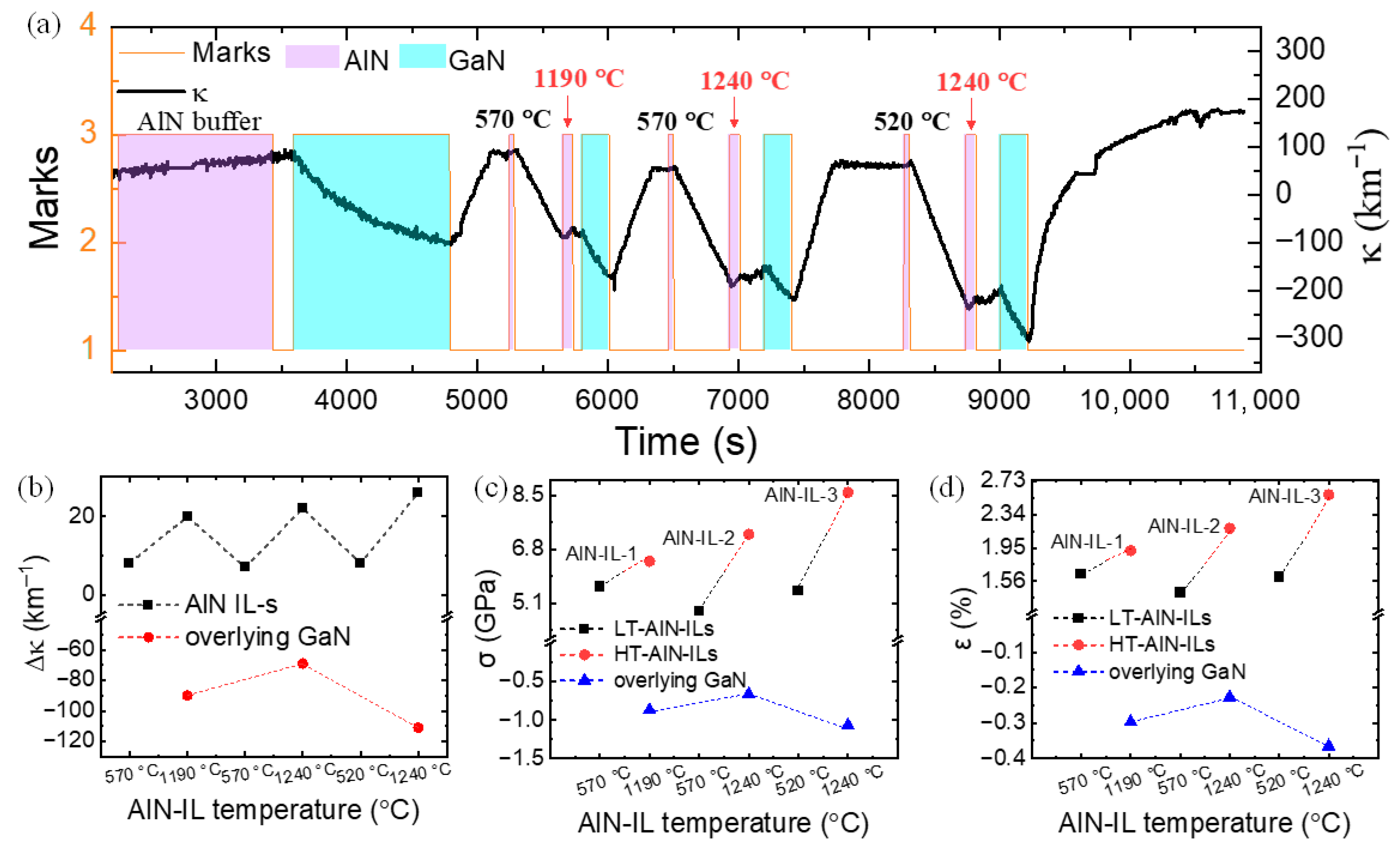
The conceptual composite LT-/HT-AlN-IL architecture was validated in sample C (Figure 5). According to the ideal AlN interlayer model, lowering the T G of the LT-AlN while raising the T G of the HT-AlN was expected to enhance the interlayer’s ability to impose compressive stress on the overlying GaN. To increase the growth temperature difference (∆ T G ) between LT-AlN and HT-AlN, three composite AlN interlayers were tested in sample D (Figure 6). All the thicknesses for the LT-AlN sublayer were 3 nm and 6 nm for the HT-AlN part. The T G for the first two LT-AlN parts was 570 °C, and that for the latter two HT-AlN parts was 1240 °C. To produce increasing ∆ T G , the first HT-AlN sublayer was grown at 1190 °C, and the last LT-AlN sublayer was grown at 520 °C.
Figure 6c,d illustrate that the stress and strain within the HT-AlN sublayer were significantly higher than those in the LT-AlN part, highlighting their respective roles. The LT-AlN sublayer facilitates relaxation of the interlayer lattice, yielding a smaller lattice constant. Conversely, the HT-AlN part promoted the formation of high-quality lateral lattice and a coherent upper interface, thereby inducing maximal strain in the overlying GaN layer. Interestingly, when the HT-AlN sublayer in the second interlayer was grown at an elevated temperature of 1240 °C—contrary to initial expectations—the compressive stress and strain in the overlying GaN above it decreased slightly. Further characterizations are needed to elucidate the underlying mechanism of this observation. However, when the T G of the LT-AlN part was lowered from 570 °C to 520 °C in the third interlayer, the compressive stress and strain in its overlying GaN were elevated significantly. This was consistent with what we expected according to the ideal AlN interlayer model.
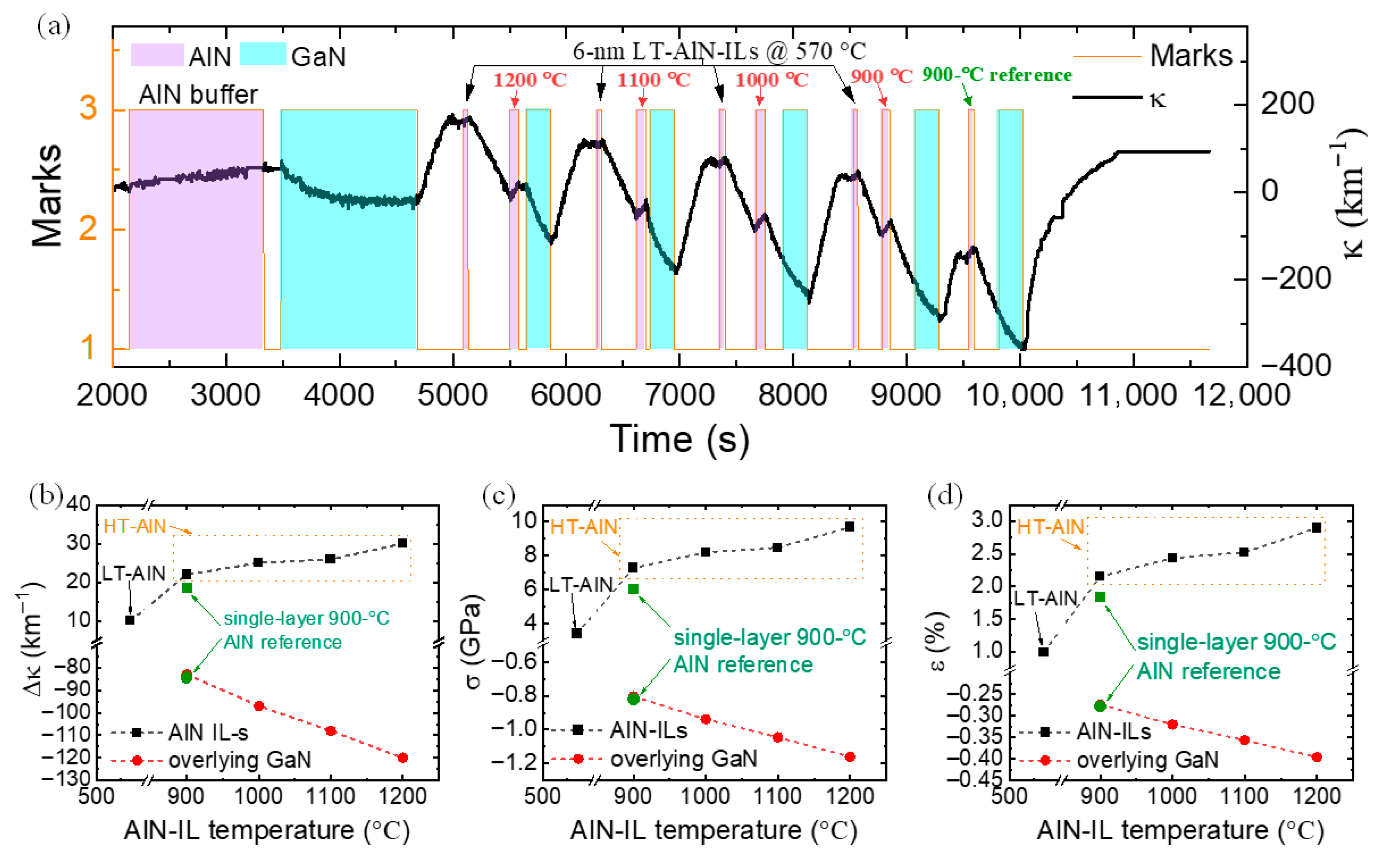
After testifying to the effectiveness of the composite LT-/HT-AlN interlayer structure, we investigated the influence of the T G of the upper HT-AlN part in the succeeding sample E (Figure 7). The T G of the LT-AlN sublayer was 570 °C, while that of the upper HT-AlN part was elevated from 900 °C to 1200 °C. Following four composite LT-/HT-AlN-ILs, a single-layer AlN-IL grown at 900 °C was inserted beneath the top GaN as a reference. All the composite ILs were of a constant total thickness of 12 nm. The thicknesses of LT-AlN and HT-AlN were both kept at 6 nm.
The curvature increment, strain, and stress in GaN exhibited a strong dependence on the T G of the upper HT-AlN part. As the T G of the HT-AlN was increased from 900 °C to 1200 °C, the overlying GaN became progressively more compressively stressed. Although a higher T G tends to increase the lattice constant of the upper HT-AlN; that layer was largely relaxed because it was grown on a relaxed LT-AlN. On the other hand, a high T G improved the quality of the upper interface between AlN-IL and GaN. This also confirmed that an ideal AlN interlayer should have a high-quality coherent upper interface. In contrast, the strain state in AlN-ILs showed much less sensitivity to growth conditions due to the large amount of relaxation within them. Compared with a conventional single-layer AlN-IL, the two-step composite AlN-ILs with HT-AlN T G > 900 °C induced larger compressive stress and strain in the overlying GaN. Quantitatively, the compressive stress in GaN σ G a N increased from ~0.82 GPa for the 900 °C single-layer reference to 1.18 GPa for the composite IL with the HT-AlN sublayer grown at 1200 °C (a 43.9% increase). The compressive stress and strain in GaN on the composite interlayer with a HT-AlN T G of 900 °C was slightly lower than that in the GaN on the reference single-layer 900-°C AlN interlayer, which is likely attributable to insufficient crystal quality of the upper 900 °C HT-AlN and the resulting suboptimal upper GaN/AlN interface.
The result from sample E (Figure 7) showed that the two-step composite structure of the LT- and HT-AlN combination is promising to produce more compressive stress in GaN than the conventional one-step AlN-IL. The growth conditions of composite LT-/HT-AlN-ILs can be optimized further. As observed in sample C (Figure 5) and sample D (Figure 6), raising the HT-AlN T G further to 1250 °C or even higher may improve the performance of the composite AlN interlayer better, which needs further study.
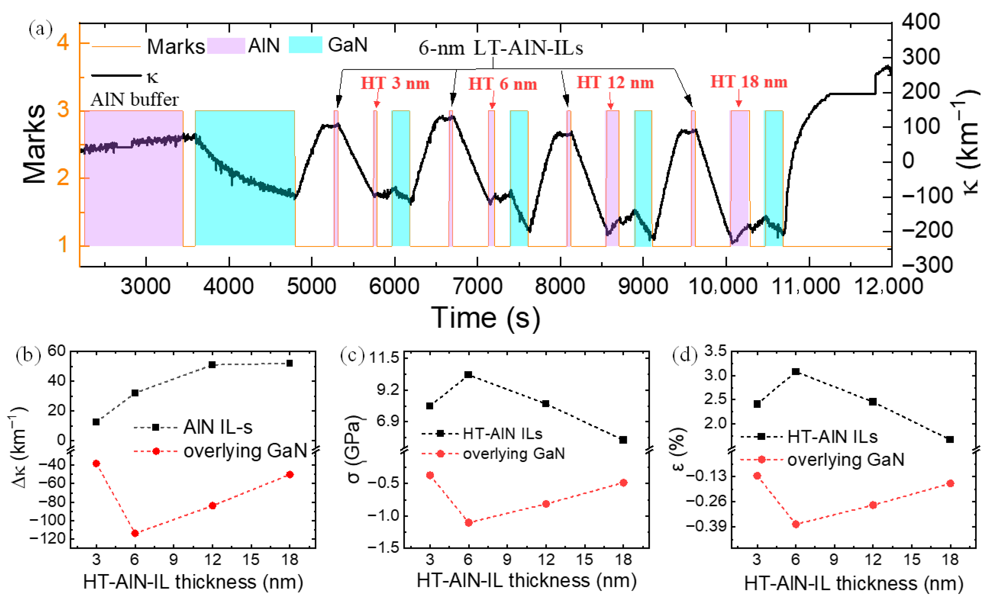
Following the HT-AlN T G series, the influence of the HT-AlN sublayer thickness was examined in sample F (Figure 8). The lower LT-AlN sublayer thickness was held constant at 6 nm, while the upper HT-AlN thickness varied from 3 nm to 18 nm to assess its ability to induce compressive stress in the overlying GaN. The highest compressive stress and strain in the overlying GaN was obtained for the composite interlayer containing 6 nm thick HT-AlN. A 3 nm HT-AlN was insufficient to form a high-quality upper interface, likely owing to incomplete coalescence of crystal grains; when the HT-AlN sublayer remained too thin, like 3 nm, the interlayer retained the morphology of the LT-AlN and failed to effectively stress the overlying GaN. Increasing the HT-AlN thickness promoted coalescence and enhanced strain introduction. But beyond a critical thickness, relaxation increased—mediated by dislocation generation—leading to reduced stress and strain in GaN. Due to the amount of high relaxation in the LT-AlN sublayer, the optimal total thickness of the composite LT-/HT-AlN-IL in this series (sample F in Figure 8) was 12 nm, which exceeded the critical thickness for relaxation onset. Notably, the strain in the lower LT-AlN remained nearly constant at ~ 1.0%, roughly one third of the strain in the HT-AlN part. This also proved the role of LT-AlN and the concept of an ideal AlN interlayer in GaN-on-Si.

3. Materials and Methods

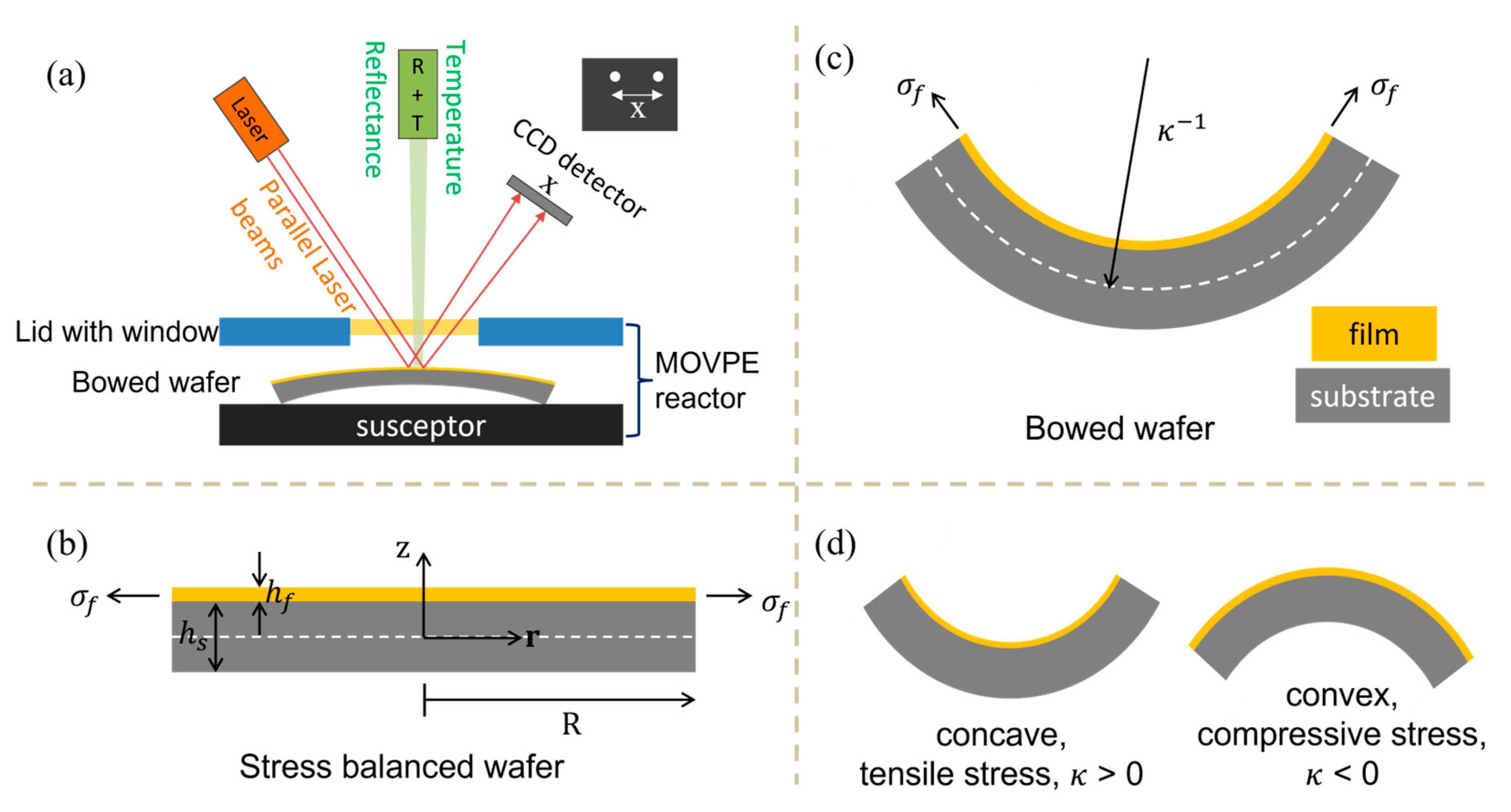
All samples were grown via metal–organic vapor phase epitaxy (MOVPE) using an AIXTRON AIX200/4HT-S system (Herzogenrath, Germany) on ShinEtsu 2-inch Si (111) substrates (Yamanashi, Japan). Prior to epitaxy, the Si wafers were wet-cleaned to remove organic contaminants and native oxides: a hydrogen peroxide/sulfuric acid mixture solution (H2SO4:H2O2 = 1:1) was used for organics stripping, followed by a hydrofluoric acid (HF) dip to remove surface oxides. All chemicals were purchased from Mitsui Chemicals (Nagoya, Japan). Growth was monitored in real time with a Laytec in situ monitoring setup (Berlin, Germany) that was equipped with incident laser beams at three wavelengths—950 nm, 632 nm, and 405 nm—to track the deposition process. In this configuration (Figure 9a), a three-spot 405 nm laser beam array was dedicated to measuring wafer curvature and asphericity: the incident parallel laser beams were reflected by the bowed wafer and detected by a charge coupled device (CCD) detector. Due to the wafer curvature, the spacing between the laser beams varies after reflection. The curvature value was calculated from the change in spacing between the reflected laser beam spots. Illustrative sketches of stress-balanced and stress-imbalanced wafers are shown in Figure 9b,c. From Figure 9d, throughout this study, the sign convention used in the curvature transition curves is κ > 0 for concave wafer (tensile film stress) and κ < 0 for convex wafer (compressive film stress).
Curvature data were directly acquired via the in situ monitoring system, from which the stress and strain values were derived by applying the following Stoney equation [30]:
κ = 6 σ f h f M s h s 2 = 6 M f · ϵ f h f M s h s 2 ,   ( h s h f )
σ f = M f · ϵ f = M s h s 2 6 · d κ d h f
ϵ f = M s h s 2 6 M f · d κ d h f
In which κ is the wafer curvature, σ f the is stress in the film, ϵ f is the strain in the film, h f and h s are the thicknesses of the film and substrate, and M f and M s are the biaxial modulus of the substrate and film.
To condition the reactor and ensure reproducible growth conditions for every single growth round, a 500 nm thick AlN dummy coating was performed prior to each growth run. To suppress nitridation of the Si surface during subsequent AlN deposition, TMAl was pre-flowed for 10 s immediately before initiating AlN buffer growth. The buffer layer consisted of 110 nm of AlN grown at 1240 °C, on which a 1140 nm GaN layer was grown. Stress-balancing AlN interlayers were then introduced, and the GaN spacer between adjacent AlN interlayers was 200 nm. The number of AlN interlayers and the GaN thickness in between the neighboring AlN interlayers can be varied to tune the final curvature and residual stress in the end of the growth at room temperature. The growth chamber pressure for the GaN and AlN were 200 mbar and 50 mbar, respectively.
Multiple AlN interlayers were grown within a single growth sample to enable direct comparisons among the AlN interlayers within each series. Three series of prototype series of AlN-interlayer inserted GaN-on-Si sample were grown (S1, S2, and S3 in Table 1). Furthermore, a 200 nm thick overlying GaN were grown above every AlN interlayer. In S1 (sample A), the PI-AlN interlayers were grown from the bottom to the up with thicknesses of 3, 6, 9, 12, 25, and 37 nm sequentially. The growth procedure for AlN-ILs grown using the precursor pulsed-injection method is illustrated in Figure 10. Following the stack of PI-ILs, a conventional AlN-IL was grown to make a comparison between PI-AlN-ILs and conventional AlN-ILs about their capability of compressive stress in the overlying GaN layers. S2 (sample B) employed composite LT-/PI-AlN-ILs: the growth conditions for the underlying low-temperature portion held constant, (LT-AlN, T G ~520 °C, thickness of 6 nm, and a V/III of ratio 1503) while the upper PI-AlN portion thickness varied from 12 nm to 36 nm. S3 comprised four samples (C to F) that probed different aspects of the composite LT/HT-AlN concept. Sample C demonstrated the effectiveness of the concept of the LT-/HT-AlN composite interlayer by comparing the conventional one-step LT-AlN-IL or HT-AlN-IL with composite LT-/HT-AlN IL. Sample D kept the T G of the underlying LT-AlN portion fixed while varying the T G of the upper HT-AlN part from 900 °C to 1200 °C to assess the influence of T G of the HT-AlN portion. Sample E was designed for testing the effects of the difference between T G of the LT-AlN and HT-AlN parts of the composite interlayer. Sample F fixed the underlying LT-AlN thickness at 6 nm and varied the upper HT-AlN part thickness from 3 nm to 18 nm to investigate the thickness effects of the HT-AlN component. Detailed structural parameters and the growth sequence are provided in Section 2.
The crystal quality information of all the samples was provided by X-ray diffraction rocking curve measurements in Figure S1 in the Supplementary Materials. The dislocation blocking and generating effects of the AlN interlayers in sample E observed by transmission electron microscopy is shown in Figure S2 in the Supplementary Materials.

4. Conclusions

Building on prior MOVPE studies of AlN interlayers for GaN-on-Si, we introduced the concept of an “ideal” AlN interlayer. In this idealized design, the AlN interlayer is engineered to be completely relaxed at its lower AlN/GaN interface (decoupling from the substrate) while maintaining a coherent, fully strained upper GaN/AlN interface. This arrangement minimizes the effective AlN lattice constant that is transmitted to the GaN and maximizes compressive stress and strain in the GaN cap, which is desirable for stress engineering and defect control. To realize this concept in practice, we proposed three prototype architectures as follows:
(1)
A single-layer AlN interlayer grown by using the precursor pulsed-injection supply technique (PI-AlN-IL).
(2)
A composite interlayer consisting of an underlying low-temperature AlN (LT-AlN) and upper PI-AlN-IL, which was noted as LT-/PI-AlN-IL.
(3)
A composite interlayer formed by an underlying LT-AlN and an overlying HT-AlN (LT-/HT-AlN-IL).
Compared with conventional single-layer AlN interlayer references, which were grown using the optimal conditions developed in previous study [23], all three prototype AlN-IL architectures tested here increased the compressive stress induced in overlying GaN layers of equal thickness by approximately 50%. The most recent relevant work on AlN interlayers in GaN-on-Si was reported by Deura et al. (2023) [8]. This was also the only study on composite AlN interlayers that consisted of LT- and HT-AlN. They obtained a compressive strain of 0.51% in overlying GaN. By comparison, the maximum compressive strain in overlying GaN achieved in this study was ~0.40%. We attribute this difference primarily to the LT/HT-AlN growth temperature combination: Deura et al. adopted 800 °C for growing the lower LT portion, whereas we used 520 °C or 570 °C in this study. The higher LT temperature in Ref. [8] likely yielded superior crystal quality of the composite interlayer, enhancing its ability to impose compressive strain on GaN. Therefore, systematic optimization of the LT/HT temperature pairing (and related process parameters) is required to maximize the compressive strain while maintaining acceptable interlayer quality.
The concept of an ideal AlN interlayer was experimentally validated using both LT-/PI-AlN and LT-/HT-AlN composite architectures. For all three prototype designs studied, the optimal total interlayer thickness was around 12 nm, which exceeded the theoretical critical thickness for AlN on GaN. Regarding the growth temperature, LT-AlN grown at T G < 600 °C provided an adequate relaxation of the lower interface. The T G of the HT-AlN part should be as high as possible (>1200 °C) to grow a high-quality upper AlN and highly strained upper GaN/AlN interface. Alternatively, the upper high-quality part can be replaced by PI-AlN grown at a moderate temperature (~700–900 °C).
Although the prototype AlN interlayer architectures and growth conditions reported here are not fully optimized, the results clearly demonstrate their enhanced stress-balancing capability in GaN-on-Si heterostructures. These findings motivate detailed structural, compositional, and defect characterization to elucidate the mechanisms by which the novel interlayers generate increased compressive stress and strain in the overlying GaN. Importantly, this work establishes new practical routes for achieving improved stress management in GaN-on-Si using substantially thinner interlayers than conventionally required.

Supplementary Materials

The following supporting information can be downloaded at: https://www.mdpi.com/article/10.3390/inorganics13090302/s1, Figure S1: XRD rocking curve measurement results for all the samples in this study; Figure S2: Transmission electron microscopy image for the cross-section of sample E.

Author Contributions

Conceptualization, C.L.; methodology, C.L. and H.S.; formal analysis, C.L. and G.L.; investigation, C.L.; resources, M.S., Y.N. and C.L.; data curation, C.L.; writing—original draft preparation, C.L. and G.L.; writing—review and editing, H.S.; visualization, C.L.; supervision, M.S. and Y.N.; project administration, C.L. and G.L.; funding acquisition, C.L. and G.L. All authors have read and agreed to the published version of the manuscript.

Funding

This work was supported by the Natural Science Foundation of Top Talent of SZTU, grant number GDRC202346; the National Natural Science Foundation of China, grant number 12304044; the Project of Engineering Technology Center of General Universities of Guangdong province, grant number 2023GCZX005; and the Foundation for Engineering Research Center of Guangdong for Compound Semiconductor Devices and Chips.

Institutional Review Board Statement

Not applicable.

Informed Consent Statement

Not applicable.

Data Availability Statement

The data presented in this study are available on request from the corresponding author due to confidentiality regulations.

Conflicts of Interest

The authors declare no conflicts of interest. The funders had no role in the design of the study; in the collection, analyses, or interpretation of data; in the writing of the manuscript; or in the decision to publish the results.

Abbreviations

The following abbreviations are used in this manuscript:
GaNGallium nitride
AlNAluminum nitride
MOVPEMetal-organic vapor phase epitaxy
PIPulsed injection
LTLow temperature
HTHigh temperature
ILInterlayer
HEMTHigh-electron-mobility transistor
LEDLight-emitting diode
CMOSComplementary Metal–Oxide Semiconductor
SiCSilicon Carbide

References

  1. Wu, N.; Xing, Z.; Li, S.; Luo, L.; Zeng, F.; Li, G. GaN-based power high-electron-mobility transistors on Si substrates: From materials to devices. Semicond. Sci. Technol. 2023, 38, 063002. [Google Scholar] [CrossRef]
  2. Zhong, Y.; Zhang, J.; Wu, S.; Jia, L.; Yang, X.; Liu, Y.; Zhang, Y.; Sun, Q. A review on the GaN-on-Si power electronic devices. Fundam. Res. 2022, 2, 462–475. [Google Scholar] [CrossRef]
  3. Zhang, Y.; Liu, C.; Zhu, M.; Zhang, Y.; Zou, X. A review on GaN-based two-terminal devices grown on Si substrates. J. Alloys Compd. 2021, 869, 159214. [Google Scholar] [CrossRef]
  4. Morimoto, Y.; Uchiho, K.; Ushio, S. Vapor Phase Epitaxial Growth of GaN on GaAs, GaP, Si, and Sapphire Substrates from GaBr3 and NH3. J. Electrochem. Soc. 1973, 120, 1783. [Google Scholar] [CrossRef]
  5. Semond, F.; Damilano, B.; Vézian, S.; Grandjean, N.; Leroux, M.; Massies, J. GaN grown on Si(111) substrate: From two-dimensional growth to quantum well assessment. Appl. Phys. Lett. 1999, 75, 82–84. [Google Scholar] [CrossRef]
  6. Bläsing, J.; Reiher, A.; Dadgar, A.; Diez, A.; Krost, A. The origin of stress reduction by low-temperature AlN interlayers. Appl. Phys. Lett. 2002, 81, 2722–2724. [Google Scholar] [CrossRef]
  7. Zhang, Z.-Z.; Yang, J.; Zhao, D.-G.; Liang, F.; Chen, P.; Liu, Z.-S. Influence of the lattice parameter of the AlN buffer layer on the stress state of GaN film grown on (111) Si. Chin. Phys. B 2023, 32, 028101. [Google Scholar] [CrossRef]
  8. Deura, M.; Nakahara, T.; Lee, W.C.; Momose, T.; Nakano, Y.; Sugiyama, M.; Shimogaki, Y. Effect of layer structure of AlN interlayer on the strain in GaN layers during metal-organic vapor phase epitaxy on Si substrates. J. Appl. Phys. 2023, 133, 165301. [Google Scholar] [CrossRef]
  9. Lin, P.-J.; Tien, C.-H.; Wang, T.-Y.; Chen, C.-L.; Ou, S.-L.; Chung, B.-C.; Wuu, D.-S. On the Role of AlN Insertion Layer in Stress Control of GaN on 150-mm Si (111) Substrate. Crystals 2017, 7, 134. [Google Scholar] [CrossRef]
  10. Hisyam, M.I.; Shuhaimi, A.; Norhaniza, R.; Mansor, M.; Williams, A.; Hussin, M.R.M. Study of AlN Epitaxial Growth on Si (111) Substrate Using Pulsed Metal–Organic Chemical Vapour Deposition. Crystals 2024, 14, 371. [Google Scholar] [CrossRef]
  11. Wośko, M.; Szymański, T.; Paszkiewicz, B.; Pokryszka, P.; Paszkiewicz, R. MOVPE growth conditions optimization for AlGaN/GaN/Si heterostructures with SiN and LT-AlN interlayers designed for HEMT applications. J. Mater. Sci. Mater. Electron. 2019, 30, 4111–4116. [Google Scholar] [CrossRef]
  12. Amano, H.; Iwaya, M.; Hayashi, N.; Kashima, T.; Nitta, S.; Wetzel, C.; Akasaki, I. Control of Dislocations and Stress in AlGaN on Sapphire Using a Low Temperature Interlayer. Phys. Status Solidi 1999, 216, 683–689. [Google Scholar] [CrossRef]
  13. Lin, Y.; Yang, M.; Wang, W.; Lin, Z.; Li, G. A low-temperature AlN interlayer to improve the quality of GaN epitaxial films grown on Si substrates. CrystEngComm 2016, 18, 8926–8932. [Google Scholar] [CrossRef]
  14. Luo, W.; Wang, X.; Guo, L.; Xiao, H.; Wang, C.; Ran, J.; Li, J.; Li, J. The effect of low temperature AlN interlayers on the growth of GaN epilayer on Si (111) by MOCVD. Superlattices Microstruct. 2008, 44, 153–159. [Google Scholar] [CrossRef]
  15. Zheng, W.; Guo, D.; Yuan, Y. Ultra-wide-bandgap semiconductors: Opportunities and challenges. Eur. Phys. J. Spéc. Top. 2025, 234, 225–230. [Google Scholar] [CrossRef]
  16. Jiang, Q.; Lewins, C.J.; Allsopp, D.W.E.; Bowen, C.R.; Wang, W.N.; Satka, A.; Priesol, J.; Uherek, F. Enhanced Photoluminescence from InGaN/GaN Quantum Wells on A GaN/Si(111) Template with Extended Three-Dimensional GaN Growth on Low-Temperature AlN Interlayer. Jpn. J. Appl. Phys. 2013, 52, 061002. [Google Scholar] [CrossRef]
  17. Liu, W.; Wang, J.F.; Zhu, J.J.; Jiang, D.S.; Yang, H. Influence of AlN thickness on strain evolution of GaN layer grown on high-temperature AlN interlayer. J. Phys. D Appl. Phys. 2007, 40, 5252. [Google Scholar] [CrossRef]
  18. Liu, C.; Kumamoto, A.; Suzuki, M.; Wang, H.; Sodabanlu, H.; Sugiyama, M.; Nakano, Y. Effects of hydrogen etching on stress control in AlN interlayer inserted GaN MOVPE on Si. Semicond. Sci. Technol. 2017, 32, 075003. [Google Scholar] [CrossRef]
  19. Shen, X.Q.; Takahashi, T.; Ide, T.; Shimizu, M. Strain states in GaN films grown on Si(111) and Si(110) substrates using a thin AlN/GaN superlattice interlayer. Phys. Status Solidi 2014, 11, 473–476. [Google Scholar] [CrossRef]
  20. Shen, X.Q.; Takahashi, T.; Kawashima, H.; Ide, T.; Shimizu, M. Realization of compressively strained GaN films grown on Si(110) substrates by inserting a thin AlN/GaN superlattice interlayer. Appl. Phys. Lett. 2012, 101, 031912. [Google Scholar] [CrossRef]
  21. Wang, H.; Liang, H.; Wang, Y.; Ng, K.; Deng, D.; Lau, K. Effects of AlGaN/AlN Stacked Interlayers on GaN Growth on Si (111. Chin. Phys. Lett. 2010, 27, 038103. [Google Scholar] [CrossRef]
  22. Li, Y.; Zhang, C.; Lin, J.; Jia, C.; Li, G. Threading dislocations reduction of GaN-on-Si by introducing AlN/3D-GaN with SiN interlayer for photodetectors. Mater. Sci. Semicond. Process. 2024, 172, 108089. [Google Scholar] [CrossRef]
  23. Liu, C.; Akihito, K.; Sodabanlu, H.; Ning, C.-Z.; Sugiyama, M.; Nakano, Y. Evolution of Crystal Quality and Stress in MOVPE GaN-on-Si (111) induced by AlN interlayers. Vacuum 2025, Submitted. [Google Scholar]
  24. Dadgar, A.; Krost, A.; Christen, J.; Bastek, B.; Bertram, F.; Krtschil, A.; Hempel, T.; Bläsing, J.; Haboeck, U.; Hoffmann, A. MOVPE growth of high-quality AlN. J. Cryst. Growth 2006, 297, 306–310. [Google Scholar] [CrossRef]
  25. Yang, J.-S.; Sodabanlu, H.; Waki, I.; Sugiyama, M.; Nakano, Y.; Shimogaki, Y. Process design of the pulse injection method for low-temperature metal organic vapor phase epitaxial growth of AlN at 800 °C. J. Cryst. Growth 2009, 311, 383–388. [Google Scholar] [CrossRef]
  26. Kröncke, H.; Figge, S.; Aschenbrenner, T.; Hommel, D. Growth of AlN by pulsed and conventional MOVPE. J. Cryst. Growth 2013, 381, 100–106. [Google Scholar] [CrossRef]
  27. Sanchez, A.M.; Pacheco, F.J.; Molina, S.I.; Stemmer, J.; Aderhold, J.; Graul, J. Critical thickness of high-temperature AIN interlayers in GaN on sapphire (0001). J. Electron. Mater. 2001, 30, L17–L20. [Google Scholar] [CrossRef]
  28. Shen, X.Q.; Takahashi, T.; Ide, T.; Shimizu, M. Mechanisms of the micro-crack generation in an ultra-thin AlN/GaN superlattice structure grown on Si(110) substrates by metalorganic chemical vapor deposition. J. Appl. Phys. 2015, 118, 125307. [Google Scholar] [CrossRef]
  29. Feng, Y.; Wei, H.; Yang, S.; Chen, Z.; Wang, L.; Kong, S.; Zhao, G.; Liu, X. Competitive growth mechanisms of AlN on Si (111) by MOVPE. Sci. Rep. 2014, 4, 6416. [Google Scholar] [CrossRef]
  30. Stoney, G.G. The tension of metallic films deposited by electrolysis. Proc. R. Soc. London Ser. A Contain. Pap. A Math. Phys. Character 1909, 82, 172–175. [Google Scholar] [CrossRef]
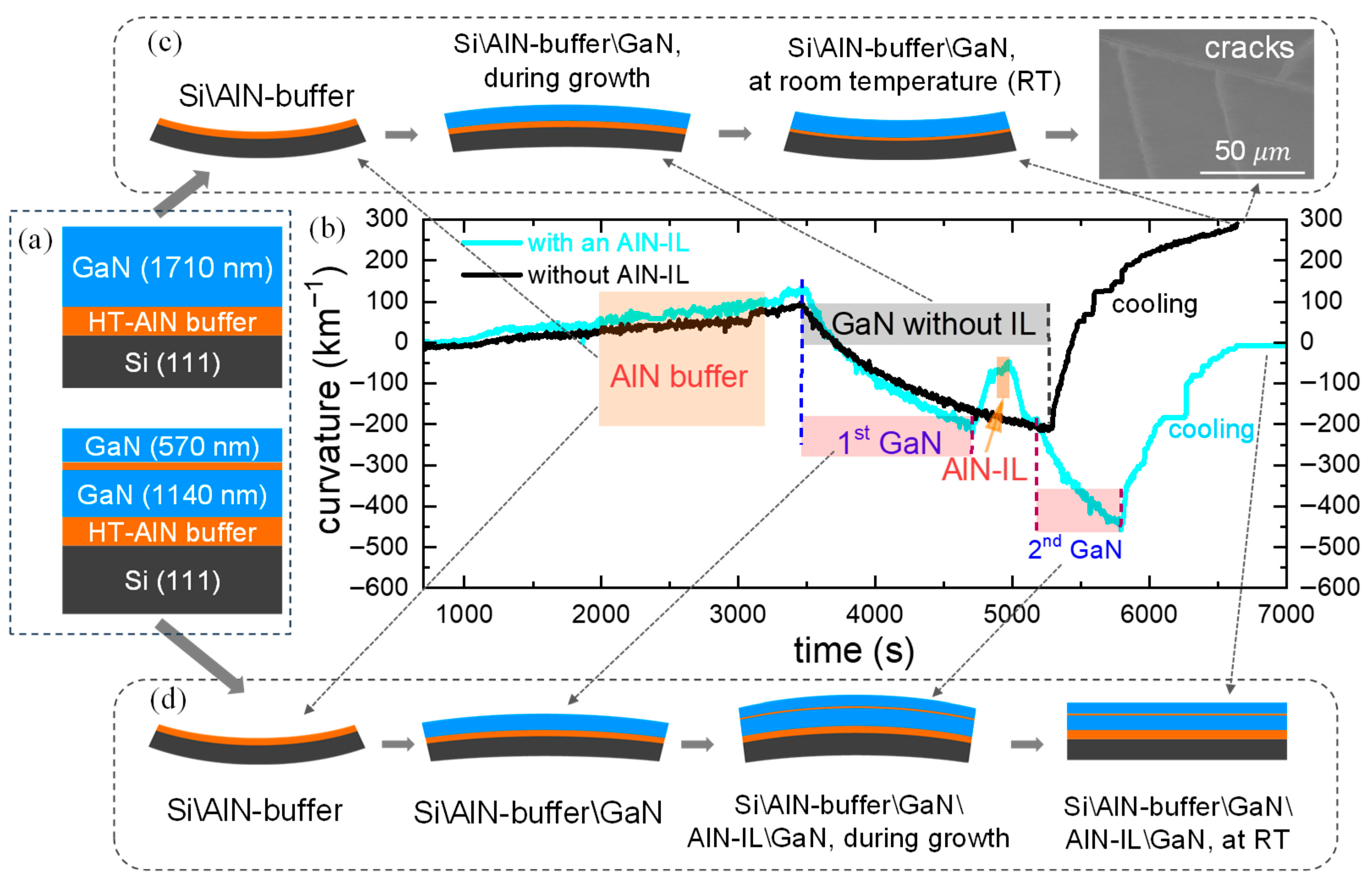
Figure 1. Curvature transition comparison between GaN-on-Si with and without an AlN-IL. (a) Sample structure, (b) curvature transition curves, (c) wafer bowing surface cracks of the sample without an AlN-IL, and (d) wafer bowing of the sample with an AlN-IL.
Inorganics 13 00302 g001
Figure 2. Properties and structures of (a) practical conventional AlN interlayers, (b,c) prototypes of unconventional AlN interlayers proposed in this study, and (d) the complete sample structure in this study.
Inorganics 13 00302 g002
Figure 3. (a) Growth sequence and curvature transition of GaN-on-Si (sample A) with AlN interlayers inserted, grown using the precursor pulsed-injection method (PI-AlN-ILs). (b) Curvature increments, (c) stress, and (d) strain of AlN interlayers and overlying GaN layers.
Inorganics 13 00302 g003
Figure 4. (a) Growth sequence and curvature transition of GaN-on-Si (sample B) with composite AlN interlayers consisting of LT-/PI-AlN-ILs; the thickness of the upper PI-AlN part varied from 12 nm to 36 nm. (b) Curvature increments, (c) stress, and (d) strain of composite AlN interlayers and overlying GaN layers.
Inorganics 13 00302 g004
Figure 5. (a) Growth sequence and curvature transition of GaN-on-Si (sample C) with single-layer AlN interlayers and composite AlN interlayers comprising of LT-/HT-AlN-ILs. (b) Curvature increments, (c) stress, and (d) strain of composite AlN interlayers and overlying GaN layers.
Inorganics 13 00302 g005
Figure 6. (a) Growth sequence and curvature transition of GaN-on-Si (sample D) with composite AlN interlayers consisting of LT-/HT-AlN-ILs. (b) Curvature increments, (c) stress, and (d) strain of composite AlN interlayers and overlying GaN layers.
Inorganics 13 00302 g006
Figure 7. (a) Growth sequence and curvature transition of GaN-on-Si (sample E) with composite AlN interlayers consisting of LT-/HT-AlN-ILs. (b) Curvature increments, (c) stress, and (d) strain of composite AlN interlayers and overlying GaN layers.
Inorganics 13 00302 g007
Figure 8. (a) Growth sequence and curvature transition of GaN-on-Si (sample F) with composite AlN interlayers consisting of LT-/HT-AlN-ILs, with the thickness of HT-AlN varied from 3 nm to 18 nm. (b) Curvature increments, (c) stress, and (d) strain of composite AlN interlayers and overlying GaN layers.
Inorganics 13 00302 g008
Figure 9. (a) In situ monitoring setup. (b) Sketch of stress balanced epitaxial wafer, (c) diagram of the definition of wafer curvature κ , and (d) sketch of wafers with the epitaxial film suffering tensile and compressive stress.
Inorganics 13 00302 g009
Figure 10. Growth procedure for AlN interlayers grown by precursor pulsed-injection supply method (PI-AlN-ILs).
Inorganics 13 00302 g010
Table 1. Growth conditions for all three prototypes of the AlN interlayers.
Interlayer TypesV/III RatioTemperature (°C)Thickness (nm)
Conventional AlN-IL1503900~9
S1: PI-AlN-ILs
(sample A)
-7203/6/9/12/25/37/conventional-AlN-IL (from bottom to top)
S2: LT-/PI-AlN ILs
(sample B)
1503LT-AlN: 520
PI-AlN: 720
LT-AlN: 6
PI-AlN: 12/18/24/36
S3: LT-/HT-AlN ILs (samples C–F)1503LT-AlN: 520, 570 (sample C-F)
HT-AlN:
(1)
1250, 1240, 1190 (samples C, E, F)
(2)
900/1000/1100/1200 (sample D)
LT-AlN: 6
HT-AlN: 3/6/12/18 (sample F)
Disclaimer/Publisher’s Note: The statements, opinions and data contained in all publications are solely those of the individual author(s) and contributor(s) and not of MDPI and/or the editor(s). MDPI and/or the editor(s) disclaim responsibility for any injury to people or property resulting from any ideas, methods, instructions or products referred to in the content.