Article

Bimetallic Ir-Sn Non-Carbon Supported Anode Catalysts for PEM Water Electrolysis

Institute of Electrochemistry and Energy System “Acad. Evgeni Budevski”, Bulgarian Academy of Sciences, Acad. G. Bonchev Str., bl. 10, 1113 Sofia, Bulgaria
*
Authors to whom correspondence should be addressed.
Inorganics 2025, 13(7), 210; https://doi.org/10.3390/inorganics13070210
Submission received: 4 May 2025 / Revised: 10 June 2025 / Accepted: 16 June 2025 / Published: 20 June 2025

Abstract

:
Nanostructured bimetallic IrSn composites deposited on the natural aluminosilicate montmorillonite were synthesized and evaluated as anode electrocatalysts for polymer electrolyte membrane electrolysis cells (PEMECs). The test series prepared via the sol–gel method consisted of samples with 30 wt. % total metal content and varying Ir:Sn ratio. The performed X-ray diffraction analysis and high-resolution transmission electron icroscopy registered very fine nanostructure of the composites with metal particles size of 2–3 nm homogeneously dispersed on the support surface and also intercalated in the basal space of its layered structure. The electrochemical behavior was investigated by cyclic voltammetry and steady-state polarization techniques. The initial screening was performed in 0.5 M H2SO4. Then, the catalysts were integrated as anodes in membrane electrode assemblies (MEAs) and tested in a custom-made PEMEC. The electrochemical tests revealed that the catalysts with Ir:Sn ratio 15:15 and 18:12 wt. % demonstrated high efficiency toward the oxygen evolution reaction during repetitive potential cycling and sustainable performance with current density in the range 140–120 mA cm−2 at 1.6 V vs. RHE during long-term stability tests. The results obtained give credence to the studied IrSn/MMT nanocomposites to be considered promising, cost-efficient catalysts for the oxygen evolution reaction (OER).

Graphical Abstract

1. Introduction

The electrolysis of water in cells with a polymer electrolyte membrane (PEMEC) is one of the most advanced technologies for producing pure hydrogen. When powered by electricity generated from renewable sources, it becomes a green, zero-emission, environmentally friendly process. However, a major challenge preventing the large-scale industrial adoption of PEMEC technology is the still high cost due to the need for noble metal catalysts from the platinum group (PGM) and the sluggish kinetics of the oxygen evolution reaction (OER)—one of the most widely studied reactions in the field of electrocatalysis [1,2]. In this context, heterointerface engineering has emerged as a promising strategy for addressing anodic intrinsic activity limitations, with a recent study reporting a RuIrOx–CeO2 ternary heterostructured catalyst featuring a strong-coupled interface that achieved impressive activity and long-term stability at high current densities [3]. On the cathode side, where the hydrogen evolution reaction (HER) occurs, a strongly electronically coupled Co@V–WOx material with an amorphous nanosheet morphology is presented. It is synthesized via a one-step electrodeposition method and demonstrates a Faradaic efficiency exceeding 92.8%, indicating enhanced catalytic activity compared to pure Pt-based catalysts [4]. The OER takes place at high potentials, and when combined with intensive gas evolution, high humidity, and elevated temperatures, it creates harsh operating conditions. These conditions lead to the gradual degradation of the classical carbon-based catalytic supports due to oxidation and corrosion of carbon. To address these challenges, extensive research over the past decades has been focused on developing novel, corrosion-resistant, and cost-efficient OER catalysts.
It is well established that IrO2 is the most effective catalyst for OER in acidic media, offering high activity and stability under extreme operating conditions. However, as precious metal oxide, IrO2 is prohibitively expensive for large-scale industrial PEMEC applications, limiting its widespread use [5].
Various efforts have been made, and new strategies have been developed to reduce catalyst costs. One approach involves enhancing the catalytic activity by synthesizing nanosized noble metal oxides with a highly developed surface area [6,7], thus increasing the number of active sites for OER and reducing the catalyst loading without compromising the process efficiency.
Another strategy is the use of high-surface-area catalytic supports, which help to minimize nanoparticle agglomeration, thereby improving catalyst utilization [8]. More recent research has focused on reducing noble-metal loading by developing mesoporous metal oxide films [9,10] and multi-component catalysts. Some of these catalysts exhibited higher electrocatalytic activity, enhanced selectivity, and stability through the realization of synergetic effects [11]. The low-cost, multi-component OER electrocatalysts are typically synthesized by combining IrO2 with one or more less expensive metal oxides, such as SnO2, Sb2O5-SnO2, Ta2O5, and TiO2 [12,13,14,15,16,17]. Among these, IrO2–SnO2 mixtures have been widely studied for their performance in oxygen evolution reactions under acidic conditions, in part due to the structural similarities between the two oxides. Tin, in the form of SnO2, is commonly used as a second component due to its chemical stability under acidic media, favorable electronic properties, and compatibility with the IrO2 structure [1,14,18,19].
In our previous study [20], we reported montmorillonite (MMT) as an alternative to conventional carbon materials for application as an anode catalytic support in hydrogen generation via electrochemical water splitting. MMT is a natural non-carbon phyllosilicate mineral—aluminosilicate from the smectite group with general formula (Na,Ca)0.33(Al,Mg)2(Si4O10) (OH)2•nH2O and a complex plate-shaped layered structure with 2:1 type sheets. It has demonstrated high surface reactivity, cation exchange capacity, and capability to intercalate metal ions, such as Fe, Cu, Ir, etc., in the interlayer basal space. The material is also characterized by large surface area, chemical stability, commercial availability, and low-cost—advantages, making it the most widely used layered silicate in nanocomposite fabrication [21,22].
Figure 1 presents a visualization of the MMT structure, obtained through the density functional theory (DFT) calculations using the projector augmented wave (PAW) method with the Perdew-Burke-Ernzerhof (PBE) exchange-correlation functional.
The recent study focuses on the preparation of novel bimetallic Ir-Sn catalysts deposited on MMT and the investigation of their structure, electrochemical performance, and stability as oxygen evolution electrocatalysts for PEMECs.

2. Results and Discussion

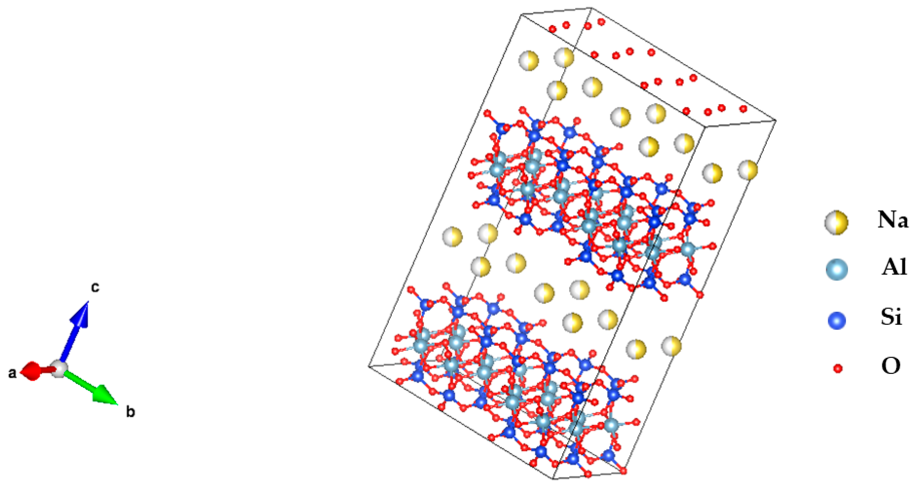
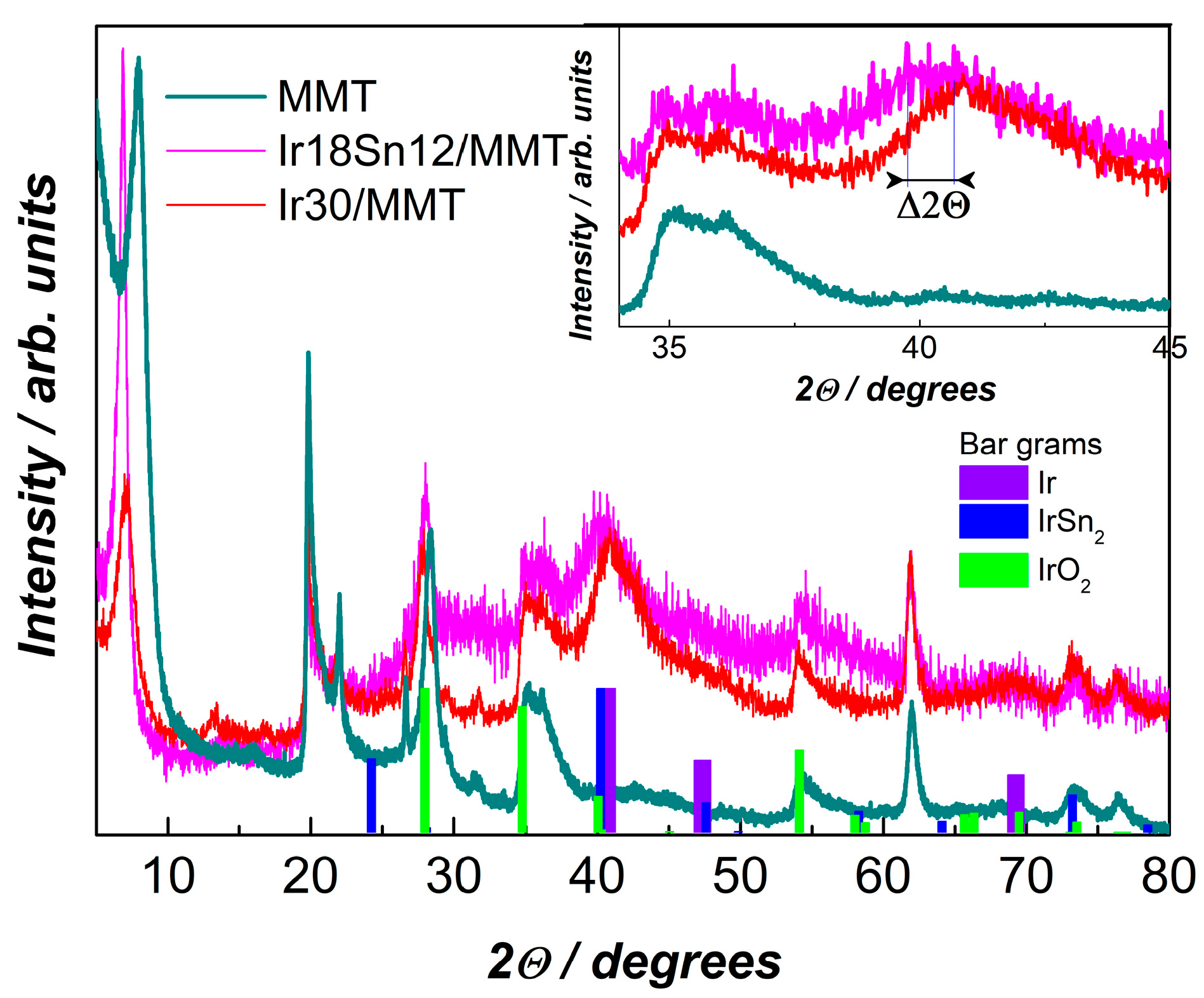
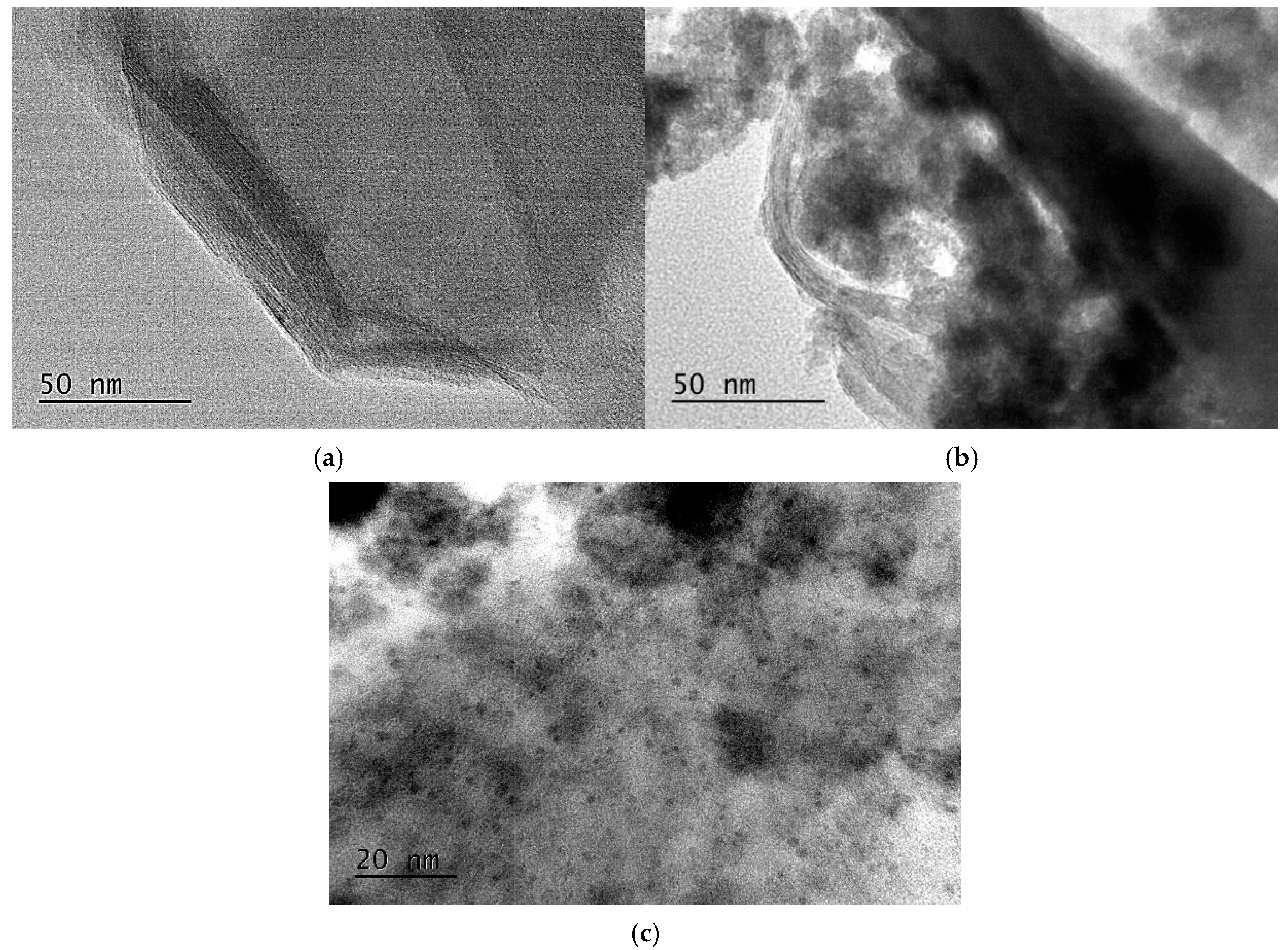
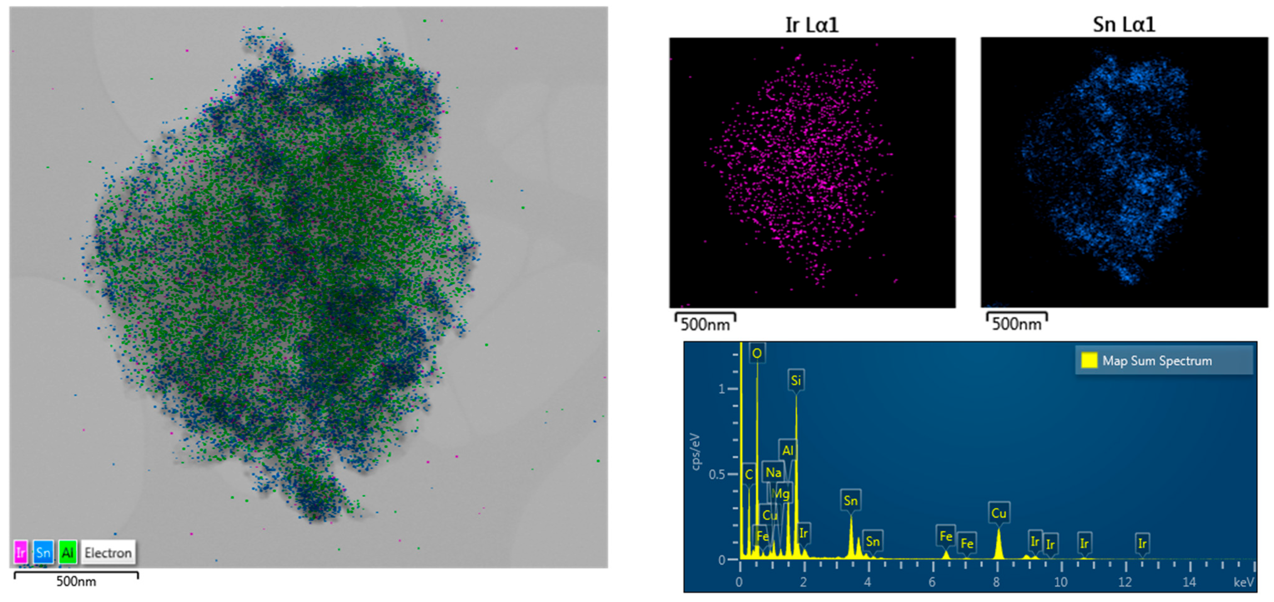
2.1. Structural Characterization

The sol–gel process used to prepare the IrSn/MMT catalysts is a widely used wet chemical technique for synthesizing materials, particularly metal oxide nanoparticles. This method is cost-effective and operates at a low reaction temperature, allowing precise control over the chemical composition of the final products [23].
X-ray diffraction patterns (XRD) obtained to assess the phase composition and crystallinity of the synthesized composite materials are shown in Figure 2. In the pattern of the sample with 10 wt. % Ir (Ir10Sn20/MMT), only the support was identified, meaning that Ir, Sn (and/or their oxides) are in an amorphous state. For the catalysts with a higher content of Ir, besides MMT, a non-destructed Ir-acac was also registered. The presence of organic residues in the catalysts can be minimized by conducting the synthesis at higher temperatures (300 °C). However, our previous studies have demonstrated that such elevated temperatures promote particle agglomeration and growth of Ir nanoparticles [20,24]. Larger particles and agglomeration result in a significant reduction in the electrochemically active surface area, which in turn leads to lower current densities and impaired electrocatalytic efficiency. Therefore, despite the incomplete removal of ligands, a temperature of 240 °C was chosen as optimal to ensure the maintenance of a very fine nanostructure with metal particles sized 2–3 nm, homogeneously dispersed on the support surface and also intercalated in the basal space of its layered structure.
In all tested catalysts, the (001) diffraction peak of MMT is shifted to smaller 2θ angles in regard to the pure MMT from 8.03° to 7.00° (Figure 2b). Such a displacement corresponds to an increase in the interlayer spacing of MMT from 1.1 nm to 1.26 nm. The observed effect has been reported previously [20] and is related to the intercalation of foreign cations, in this case, Ir, Sn, and/or their complexes in the MMT basal space [25,26].
The broad peak registered at 40.283° could be prescribed to Ir (111), although (as seen in Figure 3) it is shifted to lower 2Θ angles compared to pure Ir iridium (2Θ = 40.662°, PDF#06-0598). Alternatively, this shift might be due to the formation of an IrSn2 alloy having the strongest diffraction line (220) positioned at 2Θ = 40.217° (PDF#65-2987). The presence of oxides in an amorphous state is also not excluded. More accurate phase identification is hampered by the wide overlapping peaks of the different phases. The size of the crystallites determined by Scherrer equation [27] was very small, 2 nm.
A more detailed examination of catalyst morphologies was performed using High-Resolution Transmission Electron Microscopy (HRTEM). The results from the HRTEM analysis of the sample Ir18Sn12/MMT are presented in Figure 4. They reveal the presence of very small nanoparticles of both metals homogeneously distributed into the structure of the supporting montmorillonite.
As shown in Figure 4a, the pristine MMT exhibits a smooth layered surface, characteristic of its nanoplatelet structure. From the HRTEM images of the Ir18Sn12/MMT sample displayed in Figure 4b,c, small black dots scattered across the MMT surface and between the layers are seen, proving the presence of evenly distributed particles.
According to these figures, the metal nanoparticles have sizes in the range of 1–2 nm, which is in full accordance with the XRD data. The sheet structure of montmorillonite is clearly observed in Figure 4b, indicating that the nanoparticle deposition did not disrupt the basic structure of the MMT support. The HRTEM results are very well in line with the information obtained from the elemental EDX mapping presented in Figure 5.

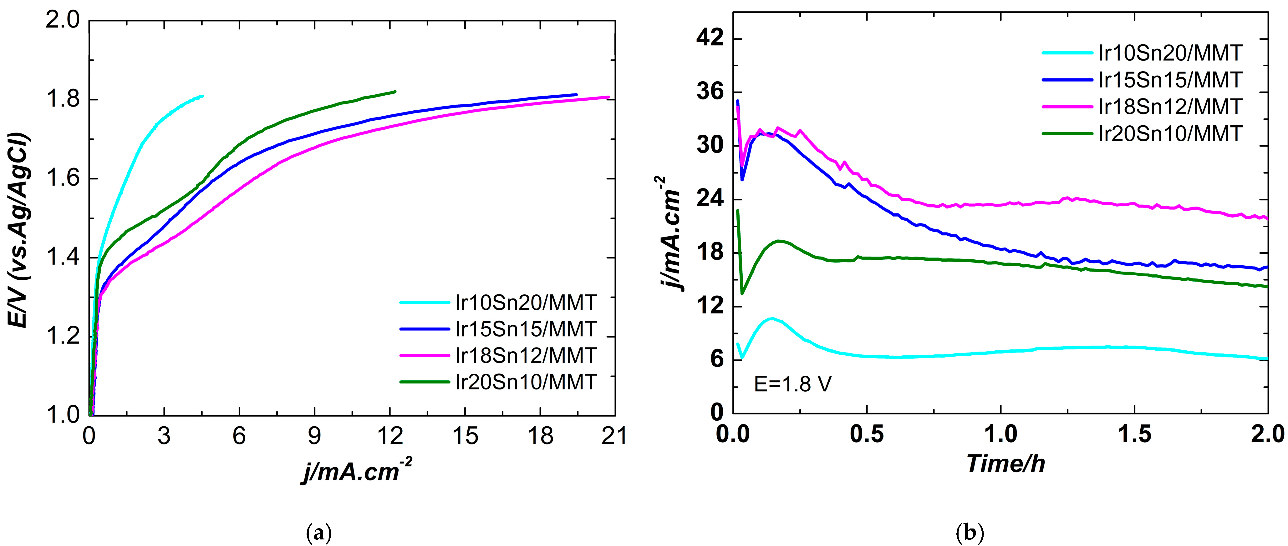
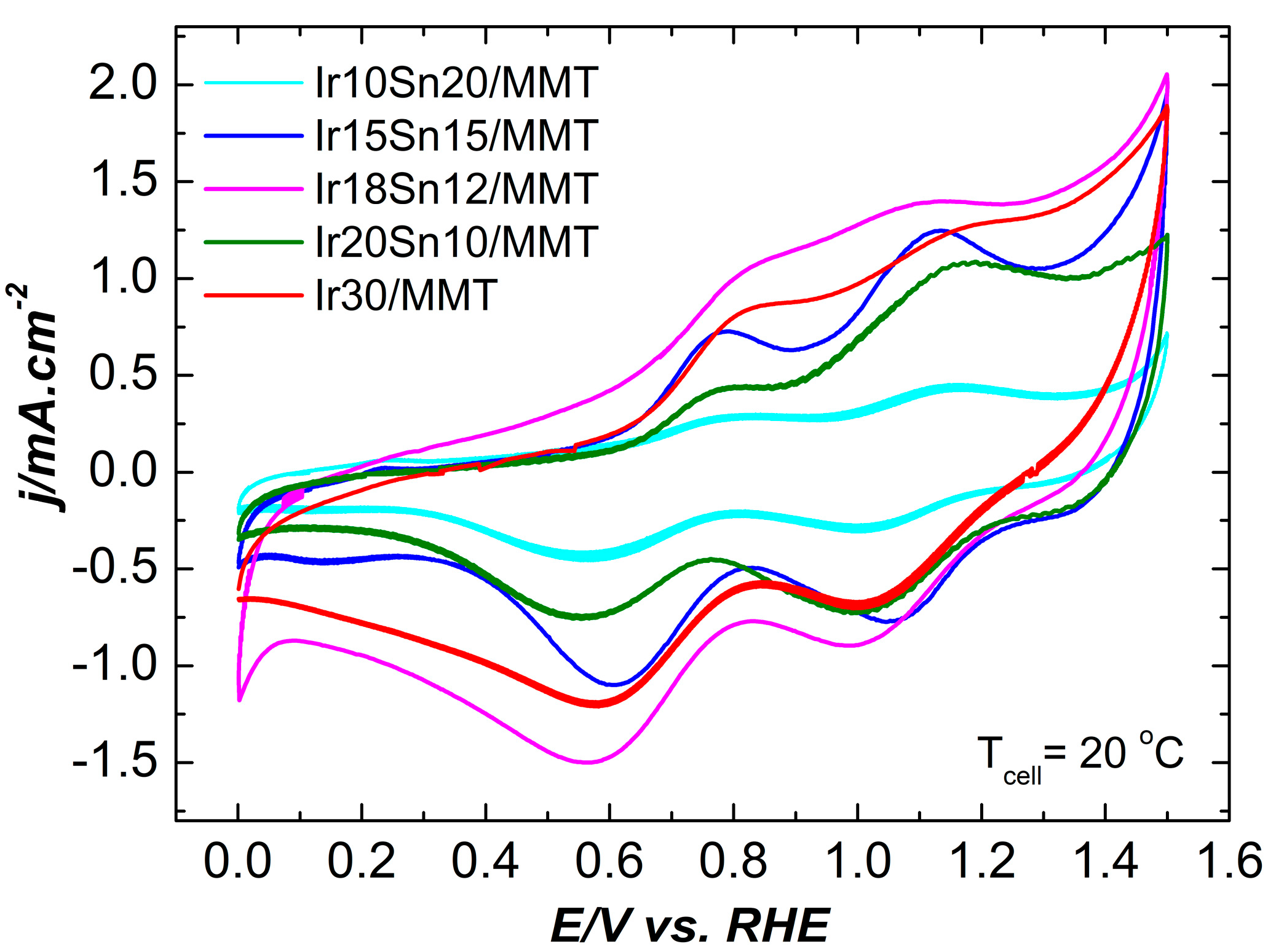
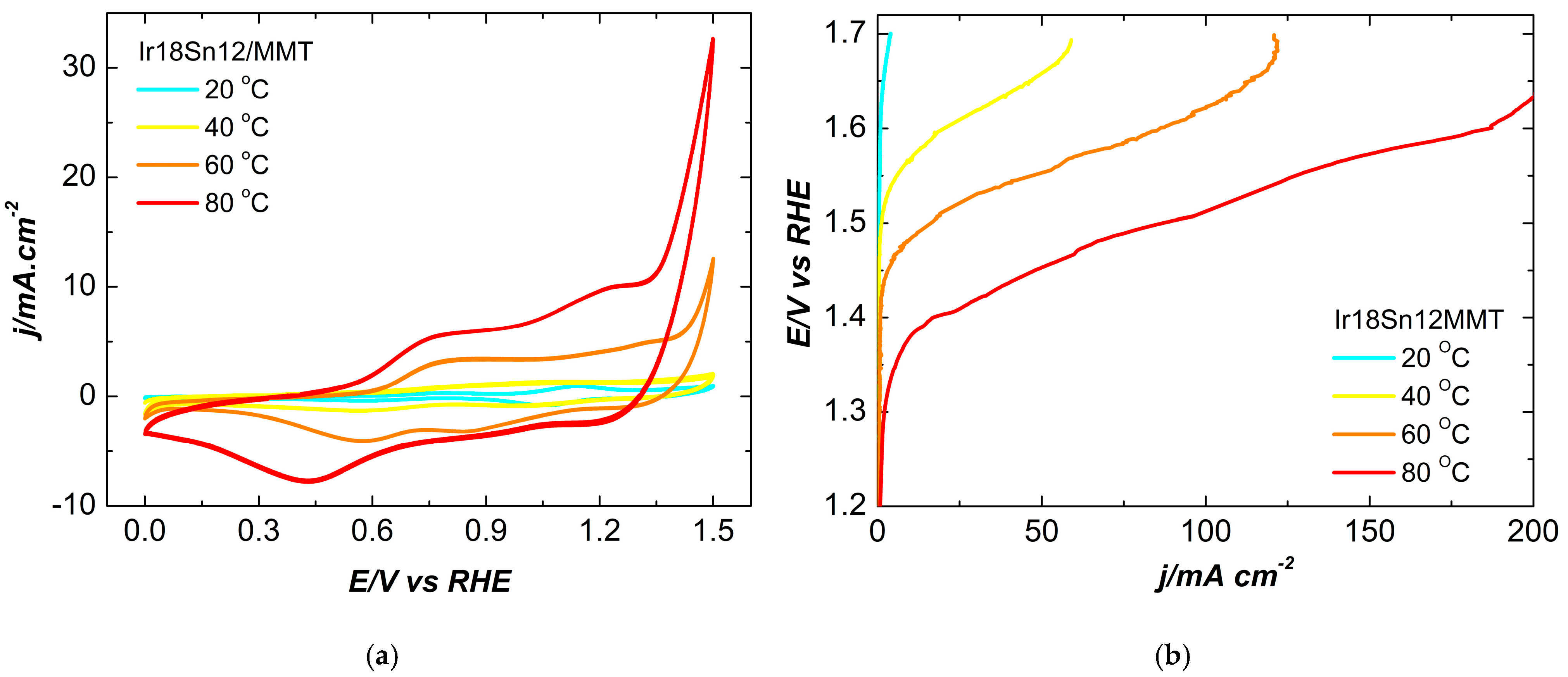
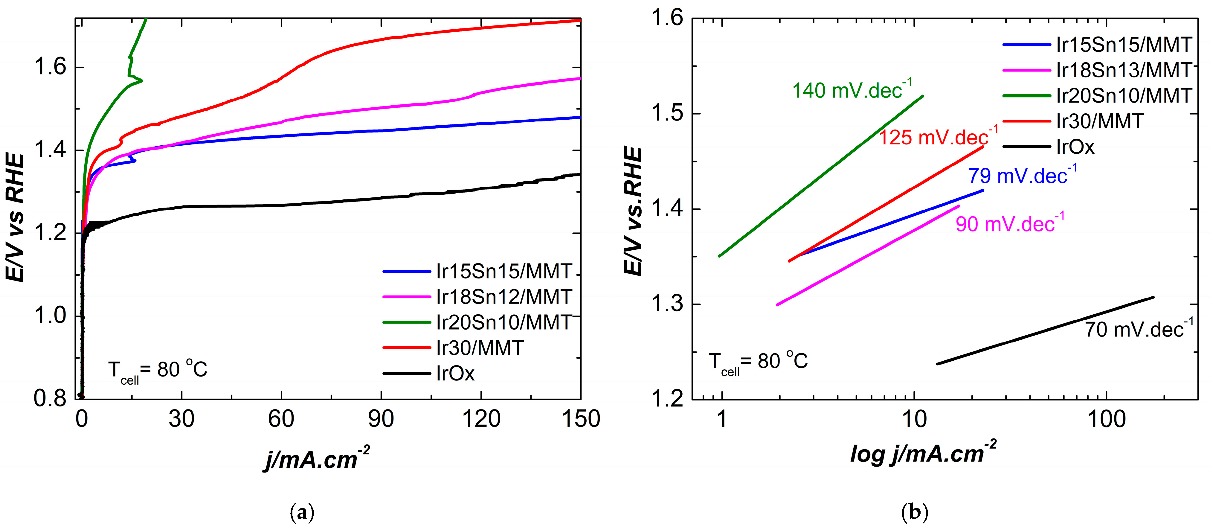
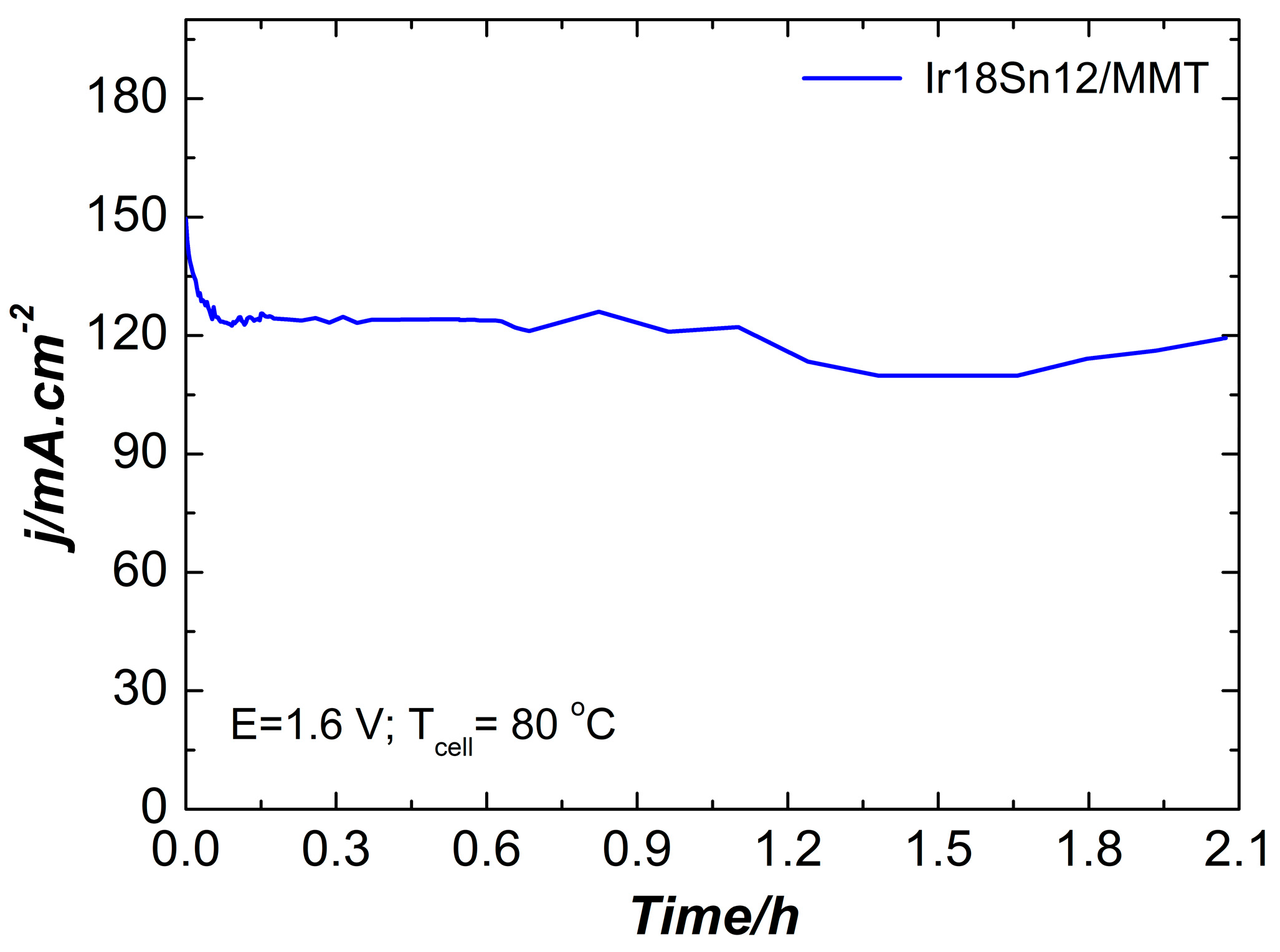
2.2. Electrochemical Characterization

Anodes containing the synthesized bimetallic IrSn/MMT catalysts were first investigated in 0.5 M H2SO4. Anodic polarization curves were recorded for each catalyst to evaluate their electrochemical behavior during OER. In Figura 6a, the measured currents are normalized to the geometric surface area of the working electrode. The OER starts at approximately 1.3 V vs. Ag/AgCl for the Ir18Sn12/MMT and Ir15Sn15/MMT catalysts, whereas for Ir10Sn20MMT and Ir20Sn10/MMT, the OER begins at more positive potentials of around 1.4 V vs. Ag/AgCl.
Potentiostatic polarization tests at a constant potential of 1.8 V were performed to investigate the stability of each catalyst (Figure 6b). For all tested samples, the current density decreases rapidly at the beginning of the test and then gradually reaches stable values. It is seen that the OER is more intensive on the catalysts with a balanced Ir:Sn ratio (15:15, 18:12). This could be attributed to the beneficial synergetic effect between Sn and Ir at these ratios, combined with better dispersion of the metal nanoparticles on the support and as a result, higher number of active sites at the electrolyte/catalyst surface and increased efficiency toward the OER. In contrast, the catalysts with Ir content of 10 wt. % and 20 wt. % Ir exhibits a decreased reaction rate, which is due to less active sites on the catalyst’s surface. For Ir10Sn20/MMT, this is due to a lower content of Ir—the more active catalyst component, while for Ir20Sn10/MMT, most probably agglomeration of metal nanoparticles commences.
To investigate the catalyst performance in a PEM electrolysis cell with Nafion 117 proton exchange membrane, MEAs were prepared using the synthesized samples as anode catalysts. Initially, the electrochemical performance was evaluated using cyclic voltammetry (CV), a well-known, highly informative, and surface-sensitive electrochemical method for fast screening in that each electrode material responds with a unique CV spectrum.
Figure 7 presents the cyclic voltammograms of IrSn/MMT catalysts integrated into MEAs and tested in PEMEC at room temperature.
A typical feature of Ir is its ability to be activated when subjected to prolonged potential cycling in the “water window” potential range [24]. Therefore, for better comparison, the curves shown in Figure 7 present the 200th cycle for each sample. All CV curves exhibit broad waves resulting from redox reactions of the active surface species being oxidized or reduced—processes often accompanied by proton exchange between the metal oxide and the electrolyte [28,29]. The shape of the CVs and the potential range where the redox waves appear suggest that the proceeding electrochemical reactions are associated with transformations between different Ir oxidation states (Ir3+/Ir4+ and/or Ir4+/Ir5+) [7] overlapped with changes in the valent state of Sn. Although the shape and area of CVs are similar for all tested samples, it can be seen that the redox peaks have the most distinct couture on the Ir15Sn15/MMT sample, suggesting better homogeneity of the catalyst structure, while the area under the CV is broader for the Ir18Sn12/MMT sample, implying higher charge transfer capacity.
All IrSn/MMT catalysts were evaluated at elevated temperatures in the range of 20 to 80 °C. Figure 8 presents the results for the Ir18Sn12/MMT catalyst, which showed the highest electrochemically active surface during the CV tests at room temperature.
The increase in the operating temperature results in a lower open-circuit voltage (OCV) and enhanced reaction rate, resp. decreased kinetic losses attributed to the lower activation energy of the OER [30]. As the measurement temperature increases, a significant expansion of the area under the cyclic voltammetry curves is observed (Figure 8a), which is induced by electrochemical and thermal activation of the catalysts, exposure of additional electroactive sites either from the catalyst bulk and/or by increasing the interparticle porosity. Additionally, a shift in the onset potential for oxygen evolution to lower values was noted with the rising temperature, indicating further catalyst activation (Figure 8b).
To compare the OER efficiency of all prepared catalysts, low-sweep voltammetry tests were conducted. Figure 9 presents the polarization curves for Ir15Sn15/MMT, Ir18Sn12/MMT, and Ir20Sn10/MMT alongside the previously reported Ir30/MMT [20] at 80 °C. The curve of commercial unsupported IrOx was also recorded and shown for comparison.
The data obtained from the tests at 20 °C and 80 °C are summarized in Table 1. They confirm the improved efficiency of all catalysts at elevated temperatures. The overpotentials at 20 °C are nearly twice as high as those at 80 °C. Among the tested samples, Ir15Sn12/MMT and Ir18Sn12/MMT outperformed the others, particularly in terms of overpotential at a given current density. For instance, at 80 °C and 10 mA·cm−2, the Ir18Sn12/MMT electrode exhibits the lowest OER overpotential of 148 mV, while the overpotentials for Ir15Sn15/MMT, Ir20Sn10/MMT, and Ir30/MMT under identical conditions are 164 mV, 290 mV, and 195 mV, respectively.
The calculated Tafel slopes (b) for Ir15Sn15/MMT (79 mV·dec−1) and Ir18Sn12/MMT (90 mV·dec−1) are comparable to that of commercial unsupported IrOx (70 mV·dec−1), indicating that these catalysts possess more favorable kinetics for the oxygen evolution reaction (OER). The observed improvement in OER efficiency is attributed to the formation of small, well-dispersed metal nanoparticles, as clearly observed by HRTEM analysis (Figure 4 and Figure 5). This results in an increased electrochemically active surface area available for the reaction.
Finally, to evaluate the durability of the catalytic performance, a membrane electrode assembly (MEA) with an Ir18Sn12/MMT anode catalyst was subjected to a 2 h chronoamperometry test at a constant potential of 1.6 V vs. RHE. The initially recorded current density of 140 mA·cm−2 during the first hour gradually decreased, then stabilized at approximately 120 mA·cm−2, fluctuating slightly around this value until the end of the experiment (Figure 10). Further in-depth studies are required to thoroughly evaluate the long-term stability of the MEA incorporating the synthesized catalysts, which will help provide a more comprehensive understanding of their durability under extended operating conditions.

3. Materials and Methods

3.1. Materials

Tin (II) acetylacetonate (Sn-acac) (99,9% trace metals basis), isopropanol (99.5%) and sulfuric acid were purchased from Sigma-Aldrich (St. Louis, MO, USA). The Iridium (III) 2,4-pentanedionate (Ir-acac) (Ir 37.5% min), Toray paper (GP-H-30), and Nafion D250 solution (5 wt. %) were purchased from Alfa Aesar (Ward Hill, MA, USA). The Nafion 117 membrane was purchased from DuPont Engineering Polymers (Wilmington, DE, USA). The commercial gas diffusion electrode (GDE) with Pt/C catalyst (20 wt. %) was purchased from Johnson Matthey (London, UK). The MMT (Cloisites Na+) was purchased from Southern Clay Products Inc. (Gonzales, TX, USA). All chemicals were used as received without further purification.

3.2. Synthesis of IrSn/MMT Electrocatalysts

Four different Ir:Sn/MMT samples with 30 wt. % total metal content and varying Ir:Sn ratio (denoted Ir20Sn10/MMT, Ir18Sn12/MMT, Ir15Sn15/MMT, and Ir10Sn20/MMT)) were synthesized through a modified sol–gel method. The calculated amounts of Ir-acac, Sn-acac, and MMT were mixed and dispersed in 20 mL isopropanol, followed by 2 h sonication at 60 °C until a fine gel was obtained. Then, the resulting gel was placed in a quartz mortar and thermally treated in a tube furnace under a hydrogen atmosphere. The tube was first purified by purging with Ar for 10 min, and then a reducing atmosphere was established by introducing H2 gas for 30 min. Afterward, the system was sealed, and the temperature was gradually increased with a heating rate of 20 °C min−1 to 240 °C and kept constant for 2 h to remove the organics and obtain MMT-supported metal nanoparticles.

3.3. Physicochemical Characterization of the Electrocatalysts

The morphology and distribution of Ir and Sn particles on the substrate were observed by High Resolution Transmission Electron Microscopy (HRTEM) and Energy Dispersive X-ray Spectrometry (EDX). HRTEM images were recorded using a JEOL JEM-2100 transmission electron microscope (JEOL Ltd., Tokyo, Japan) equipped with an XEDS system (X-MAXN 80T) fromOxford Instruments (Abingdon, Oxfordshire, UK) and a CCD Camera (ORIUS 1000, 11 Mp) from Gatan Inc. (Pleasanton, CA, USA) operated at an accelerating voltage of 200 kV. Image analysis was performed using Digital Micrograph software. (Version 3.32, Gatan Inc., USA)
X-ray diffractor (XRD) measurements were carried out using a Philips ADP15 diffractometer (Philips Analytical, Eindhoven, Netherlands) with Cu-Kα radiation (λ = 1.54178 Å) at a constant rate of 0.02°s−1 over an angle range 2θ = 4° ÷ 80°.

3.4. Electrochemical Measurements

All electrochemical measurements were performed using Gamry Reference 3000 Potentiostat/Galvanostat (Gamry Instruments, Warminster, PA, USA). The activity and stability of the prepared IrSn/MMT catalysts toward OER were characterized firstly in a three-electrode glass cell using an aqueous solution of 0.5 M H2SO4 as electrolyte. Pt wire was used as a counter electrode and saturated Ag/AgCl electrode as a reference electrode. The metal loading in all samples was 0.5 mgIrSncm−2, and the working area of the test electrodes—0.5 cm−2. The anodic OER steady-state polarization curves in Ar saturated electrolyte were recorded to assess the OER activity of the catalysts. The potential was scanned from the open circuit (OC) potential to 1.8 V at a scan rate of 1 mV s−1. Chronoamperometry experiments at a constant potential of 1.8 V were conducted to evaluate the long-term stability of the catalysts.

3.5. Assembly of MEA and PEMEC Tests

The bimetallic IrSn/MMT catalyst ink and membrane electrode assemblies (MEAs) were prepared following a previously reported procedure [7,19]. Briefly, the synthesized catalyst was mixed with a 5 wt. % Nafion® dispersion (used as an ionomer) and isopropanol as the solvent. The resulting ink was manually coated onto carbon paper gas diffusion layers (GDL). The metal loading was maintained at 0.5 mgIrSn·cm−2 for all samples.
The prepared electrodes were then integrated as anodes in MEAs using a Nafion® 117 membrane (Alfa Aesar) as the polymer electrolyte. The cathode and reference electrodes were cut from a commercial gas diffusion electrode (GDE) containing a carbon-supported platinum catalyst (20 wt. % Pt/C, 0.2 mgPt·cm−2). Finally, these electrodes were hot-pressed onto the membrane to complete the assembly.
The catalytic performance was evaluated using a custom-made single-cell PEM electrolyzer with an active area of 1 cm2. Experiments were performed at both room temperature and elevated temperatures ranging from 40 to 80 °C. Cyclic voltammograms (CVs) were recorded between the hydrogen and oxygen evolution regions at a scan rate of 100 mV·s−1. Additionally, linear sweep voltammograms (LSVs) were collected at a scan rate of 1 mV·s−1. Catalyst durability was assessed via chronoamperometry at a constant potential of 1.6 V vs. RHE.

4. Conclusions

Nanostructured bimetallic IrSn/MMT composites were successfully synthesized and evaluated as anode catalysts for the electrolysis of water in PEMEC. Structural characterization using XRD and HRTEM revealed homogeneous dispersion of both Ir and Sn nanoparticles on the surface of the support as well as intercalation in the interlayer space of the MMT.
The electrochemical investigations demonstrated that the samples with a balanced metal ratio, namely Ir18Sn12/MMT and Ir15Sn15/MMT, exhibit superior OER efficiency with lower overpotential and smaller Tafel slopes compared to the other compositions. The MEA with Ir18Sn12/MMT anode achieved the highest performance with a sustainable current density of around 120 mA.cm−2 at only 1.6 V in a long-term stability test in comparison with other presented samples.
Overall, the results indicate that optimizing the Ir:Sn ratio leads to a synergistic effect that enhances catalytic efficiency in PEM electrolysis. The superior performance of Ir18Sn12/MMT and Ir15Sn15/MMT positioned them as cost-effective alternatives to pure Ir catalysts for OER application in PEMECs. Although the exact mechanism behind the observed synergetic interactions between Ir and Sn and their intercalation in the complex layered structure of the catalytic support is not yet fully understood, the results proved enhanced catalyst utilization, efficiency, and stability under operating conditions in PEMEC.

Author Contributions

Conceptualization, I.B., E.L. and E.S.; Data curation, I.B.; Formal analysis, I.B., E.L. and D.P.; Investigation, I.B. and D.P.; Methodology, I.B., G.B. and D.P.; Supervision, E.L., G.B. and E.S.; Validation, G.B. and E.S.; Visualization, I.B.; Writing—original draft, I.B.; Writing—review and editing, E.L. and E.S. All authors have read and agreed to the published version of the manuscript.

Funding

The experiments were performed using equipment of project BG16RFPR002-1.014-0009 form 31 March 2025 “Development and Sustainability of Centre of Competence HITMOBIL”, funded by Program “Research, Innovations and Digitalization for Smart Transformation” 2021–2027.

Institutional Review Board Statement

Not applicable.

Informed Consent Statement

Not applicable.

Data Availability Statement

The original contributions presented in this study are included in the article.

Conflicts of Interest

The authors declare no conflicts of interest.

Abbreviations

The following abbreviations are used in this manuscript:
PEMECPolymer electrolyte membrane electrolysis cell
HRTEMHigh resolution transmission electron microscopy
EDXEnergy-dispersive X-ray spectrometry
XRDX-ray diffraction patterns
MEAMembrane electrode assembly
OEROxygen evolution reaction
RHEReference hydrogen electrode
PGMPlatinum group metal
MMTMontmorillonite
DFTDensity functional theory
PAWProjector augmented wave
PBEPerdew-Burke-Ernzerhof
GDEGas diffusion electrode
OCOpen circuit
OCVOpen-circuit voltage
LSVLinear sweep voltammetry
CVCyclic voltammograms

References

  1. Li, G.; Yu, H.; Wang, X.; Sun, S.; Li, Y.; Shao, Z.; Yi, B. Highly effective IrxSn1-xO2 electrocatalysts for oxygen evolution reaction in the solid polymer electrolyte water electrolyser. Phys. Chem. Chem. Phys. 2013, 15, 2858–2866. [Google Scholar] [CrossRef]
  2. Wang, C.; Lan, F.; He, Z.; Xie, X.; Zhao, Y.; Hou, H.; Guo, L.; Vignesh, M.; Shao, Q.; Liu, H.; et al. Iridium-based Catalysts for Solid Polymer Electrolyte Electrocatalytic Water Splitting. ChemSusChem 2019, 12, 1576–1590. [Google Scholar] [CrossRef] [PubMed]
  3. Sun, K.; Mao, W.; Jin, L.; Shi, W.; Niu, W.; Wei, C.; He, Y.; Yan, Q.; Wang, R.; Li, Y.; et al. Enhancing heterointerface coupling for durable industrial-level proton exchange membrane water electrolysis. Angew. Chem. 2025, 137, e202502250. [Google Scholar] [CrossRef]
  4. Wu, Y.; Yu, Z.; Tong, Y.; Lin, C.; Zhang, N.; Chen, P. Interfacial bridge bonds induced strong electronic coupling of Co@V-WOx catalyst for enhanced concurrent co-electrolysis performance. Adv. Funct. Mater. 2025, 2502104. [Google Scholar] [CrossRef]
  5. Lin, H.Y.; Li, W.J.; Lin, M.Y.; Xu, H.G.; Fang, S.R.; Lv, Y.; Li, W.; Guo, J.; Fu, H.Q.; Yuan, H.Y.; et al. Leaching-induced Ti trapping stabilizes amorphous IrOx for proton exchange membrane water electrolysis. Angew. Chem. 2025, 137, e202504212. [Google Scholar]
  6. Song, S.; Zhang, H.; Ma, X.; Shao, Z.; Baker, R.T.; Yi, B. Electrochemical Investigation of Electrocatalysts for the Oxygen Evolution Reactionin PEM Water Electrolyzers. Int. J. Hydrogen Energy 2018, 33, 4955–4961. [Google Scholar] [CrossRef]
  7. Slavcheva, E.; Radev, I.; Bliznakov, S.; Topalov, G.; Andreev, P.; Budevski, E. Sputtered Iridium Oxide Films as Electrocatalysts for Water Splitting Via PEM Electrolysis. Electrochim. Acta 2007, 52, 3889–3894. [Google Scholar] [CrossRef]
  8. Khan, M.A.; Zhao, H.; Zou, W.; Chen, Z.; Cao, W.; Fang, J.; Xu, J.; Zhang, L.; Zhang, J. Recent Progresses in Electrocatalysts for Water Electrolysis. Electrochem. Energy Rev. 2018, 4, 483–530. [Google Scholar] [CrossRef]
  9. Ortel, E.; Reier, T.; Strasser, P.; Kraehnert, R. Mesoporous IrO2 Films Templated by PEO-PB-PEO Block-Copolymers: Self-Assembly, Crystallization Behavior, and Electrocatalytic Performance. Chem. Mater. 2011, 23, 3201–3209. [Google Scholar] [CrossRef]
  10. Li, G.; Yu, H.; Wang, X.; Yang, D.; Li, Y.; Shao, Z.; Yi, B. Triblock Polymer Mediated Synthesis of Ir-Sn Oxide Electrocatalysts for Oxygen Evolution Reaction. J. Power Sources 2014, 249, 175–184. [Google Scholar] [CrossRef]
  11. Ardizzone, S.; Trasatti, S. Interfacial Properties of Oxides with Technological Impact in Electrochemistry. Adv. Colloid Interface Sci. 1996, 64, 173–251. [Google Scholar] [CrossRef]
  12. Mazur, P.; Polonsky, J.; Paidar, M.; Bouzek, K. Non-conductive TiO2 as the Anode Catalyst Support for PEM Water Electrolysis. Int. J. Hydrogen Energy 2012, 37, 12081–12088. [Google Scholar] [CrossRef]
  13. Wu, X.; Scott, K. RuO2 Supported on Sb-doped SnO2 Nanoparticles for Polymer Electrolyte Membrane Water Electrolysers. Int. J. Hydrogen Energy 2011, 36, 5806–5810. [Google Scholar] [CrossRef]
  14. Marshall, A.; Børresen, B.; Hagen, H.; Tsypkin, M.; Tunold, R. Electrochemical Characterisation of IrxSn1−xO2 Powders as Oxygen Evolution Electrocatalysts. Electrochim. Acta 2006, 51, 3161–3167. [Google Scholar] [CrossRef]
  15. Chen, G.H.; Chen, X.M.; Yue, P.L. Electrochemical Behavior of Novel Ti/IrOx−Sb2O5−SnO2 Anodes. J. Phys. Chem. B 2002, 106, 4364–4369. [Google Scholar] [CrossRef]
  16. Marshall, A.; Haverkamp, R. Electrocatalytic Activity of IrO2–RuO2 Supported on Sb-Doped SnO2 Nanoparticles. Electrochim. Acta 2010, 55, 1978–1984. [Google Scholar] [CrossRef]
  17. Di Blasi, A.; D’Urso, C.; Baglio, V.; Antonucci, V.; Arico, A.; Ornelas, R.; Matteucci, F.; Orozco, G.; Beltran, D.; Meas, Y.; et al. Preparation and Evaluation of RuO2–IrO2, IrO2–Pt and IrO2–Ta2O5 Catalysts for the Oxygen Evolution Reaction in an SPE Electrolyzer. J. Appl. Electrochem. 2009, 39, 191–196. [Google Scholar] [CrossRef]
  18. Jiang, G.; Yu, H.; Hao, J.; Chi, J.; Fan, Z.; Yao, D.; Qin, B.; Shao, Z. An Effective Oxygen Electrode Based on Ir0.6Sn0.4O2 for PEM Water Electrolyzers. J. Energy Chem. 2019, 39, 23–28. [Google Scholar] [CrossRef]
  19. Felix, C.; Maiyalagan, T.; Pasupathi, S.; Bladergroen, B.; Linkov, V. Synthesis. Characterisation and Evaluation of IrO2 Based Binary Metal Oxide Electrocatalysts for Oxygen Evolution Reaction. Int. J. Electrochem. Sci. 2012, 7, 12064–12077. [Google Scholar] [CrossRef]
  20. Boshnakova, I.; Lefterova, E.; Slavcheva, E. Investigation of Montmorillonite as Carrier for OER. Int. J. Hydrogen Energy 2018, 43, 16897–16904. [Google Scholar] [CrossRef]
  21. Jiang, B.; Dou, B.; Wang, K.; Zhang, C.; Song, Y.; Chen, H.; Xu, Y. Hydrogen Production By Chemical Looping Steam Reforming of Ethanol Using NiO/Montmorillonite Oxygen Carriers in a Fixed-Bed Reactor. Chem. Eng. J. 2016, 298, 96–106. [Google Scholar] [CrossRef]
  22. Martín, Z.; Jiménez, I.; Gómez, M.A.; Ade, H.W.; Kilcoyne, D.A.; Hernádez-Cruz, D. Spectro microscopy Study of Intercalation and Exfoliation in Polypropylene/Montmorillonite Nanocomposites. J. Phys. Chem. B 2009, 113, 11160–11165. [Google Scholar] [CrossRef] [PubMed]
  23. Bokov, D.; Jalil, A.T.; Chupradit, S.; Suksata, W.; Ansari, M.J.; Shewael, I.H.; Valiev, G.H.; Kianfar, E. Nanomaterial by sol gel method: Synthesis and application. Adv. Mater. Sci. Eng. 2021, 2021, 5102014. [Google Scholar] [CrossRef]
  24. Slavcheva, E.; Borisov, G.; Lefterova, E.; Petkucheva, E.; Boshnakova, I. Ebonex Supported Iridiumas Anode Catalystfor PEM Water Electrolysis. Int. J. Hydrogen Energy 2015, 40, 11356–11361. [Google Scholar] [CrossRef]
  25. Fukushima, Y.; Inagaki, S. Synthesis of an Intercalated Compound of Montmorillonite and 6-Polyamide. J. Incl. Phenom. 1987, 5, 473–482. [Google Scholar] [CrossRef]
  26. Li, Y.; Wang, X.; Wang, J. Cation Exchange, Interlayer Spacing, and Thermalanalysis of Na/Ca-Montmorillonite Modified with Alkaline and Alkalineearth Metal Ions. J. Therm. Anal. Calorim. 2012, 110, 1199–1206. [Google Scholar] [CrossRef]
  27. Lanfgord, J.; Wilson, A.A. Survey and some New results in the determination of crystallite size. J. Appl. Crystallogr. 1978, 11, 102–113. [Google Scholar]
  28. Burke, L.; Whelan, D.A. Voltammetric Investigation of the Charge Storage Reactions of Hydrous Iridium Oxide Layers. J. Electroanal. Chem. Interfacial Electrochem. 1984, 162, 121–141. [Google Scholar] [CrossRef]
  29. Lee, W.H.; Kim, H. Oxidized Iridium Nanodendrites as Catalysts for Oxygen Evolution Reactions. Catal. Commun. 2011, 12, 408–411. [Google Scholar] [CrossRef]
  30. Bonanno, M.; Müller, K.; Bensmann, B.; Hanke-Rauschenbach, R.; Aili, D.; Franken, T.; Chromik, A.; Peach, R.; Freiberg, A.T.S.; Thiele, S.; et al. Review and Prospects of PEM Water Electrolysis at Elevated Temperature Operation. Adv. Mater. Technol. 2024, 9, 2300281. [Google Scholar] [CrossRef]
Figure 1. DFT visualization Montmorillonite structure.
Inorganics 13 00210 g001
Figure 2. (a) XRD patternsand, (b) the enlarged XRD patterns from 6° to 9° of IrSn/MMT catalysts, pure MMT, Ir-acac and bar-gram of Ir-acac precursor according Inorganic Crystal Structure Database (ICSD, PDF#23-1711).
Inorganics 13 00210 g002
Figure 3. Comparison of XRD patterns of Ir18Sn12/MMT, Ir30/MMT, and MMT, inset graph show the zoom-in (34°–45°) XRD patterns.
Inorganics 13 00210 g003
Figure 4. HRTEM images of (a) pure MMT and (b,c) Ir18Sn12/MMT70 catalyst.
Inorganics 13 00210 g004
Figure 5. Elemental mapping images and EDX data of Ir18Sn12/MMT70.
Inorganics 13 00210 g005
Figure 6. Electrochemical performance of the prepared catalysts in 0.5 M H2SO4 at room temperature: (a) Linear sweep voltammetry with a scan rate of 1 mV s−1; (b) Potentiostatic polarization curves at 1.8 V vs. Ag/AgCl.
Inorganics 13 00210 g006
Figure 7. Cyclic voltammograms of the catalysts under study in PEM cell at room temperature, potential scan rate 100 mV s−1, metal loading 0.5 mgIrSncm−2; 200th cycle.
Inorganics 13 00210 g007
Figure 8. Electrochemical performance of the catalyst Ir18Sn12MMT in PEMEC at 20 °C, 40 °C and 80 °C: (a) Cyclic voltammetry at a potential scan rate of 100 mV s−1; (b) Anodic polarization curves at a potential scan rate of 1 mV s−1.
Inorganics 13 00210 g008
Figure 9. Comparison of the bimetallic catalysts IrSn/MM, Ir30/MMT, and commercial IrOx catalysts performance in PEM single cell at 80 °C. (a) Linear sweep voltammetry (LSV) curves at a scan rate of 1 mV s−1; (b) Tafel slopes corresponding to (a).
Inorganics 13 00210 g009
Figure 10. Potentiostatic polarization curve of Ir18Sn12/MMT at 1.8 V vs. RHE, Tcell = 80 °C for 2 h.
Inorganics 13 00210 g010
Table 1. Summary of oxygen evolution reaction performance of the tested samples in PEM electrolysis cell at 20 °C and 80 °C.
Temperature20 °C80 °C
Samplesƞ/mV
at j = 1 mA.cm−2
E(OER) V
at j = 1 mA.cm−2
Tafel Slope
mV.dec−1
j/mA
at 1.8 V
ƞ/mV
at j = 10 mA.cm−2
E(OER) V
at j = 10 mA.cm−2
Tafel Slope
mV.dec−1
j/mA
at 1.6 V
Ir15Sn15/MMT4071.6312012.31641.3979240
Ir18Sn12/MMT3441.5718012.81481.3790220
Ir20Sn10/MMT3901.621708.12901.5214014
Ir30/MMT------2406.91941.4212565
IrOx 250 nm 01.2370-
Disclaimer/Publisher’s Note: The statements, opinions and data contained in all publications are solely those of the individual author(s) and contributor(s) and not of MDPI and/or the editor(s). MDPI and/or the editor(s) disclaim responsibility for any injury to people or property resulting from any ideas, methods, instructions or products referred to in the content.

