Abstract
The primary aim of this research was to identify the optimal experimental conditions for obtaining aligned carbon nanotubes, temporarily leaving aside aspects such as the purity of carbon nanotubes, which is nonetheless crucial for potential applications in the field of nanoelectronics. The predefined alignment of CNTs can significantly influence the performance and efficiency of electronic components. In this study, two different catalytic supports based on cobalt nanoparticles, Co/SiO2/Si and Co/C, have been utilized and compared in the catalytic chemical vapor deposition (CCVD) synthesis of CNTs. Various parameters have been examined, including the nature and thickness of the catalyst, the reaction temperature, and the pressure of the acetylene mixture entering the reactor. The results indicate that the optimal temperature for the Co/SiO2/Si catalyst is 800 °C, while for the Co/C catalyst, it is 450 °C. The optimal Co layer thickness should be between 20 and 30 Å. CNT growth occurs from the top in the Co/C system, whereas bottom-up growth is characteristic of the Co/SiO2/Si catalyst, making the latter more suitable for the synthesis of CNTs intended for nanoelectronic devices.
1. Introduction
Carbon nanotubes were synthesized since the 1950s, but only in 1991 were they identified with certainty by S. Iijima [1]. The structure of carbon nanotubes is made of one or more sheets of rolled graphene. The tubes formed by a single sheet are called single-wall carbon nanotubes (SWCNT), while those formed by several concentric layers are called multi-wall carbon nanotubes (MWCNT). They can be straight or curled carbon nanotubes [2]. They have a diameter that can reach up to 100 nm and a length that grows up to several millimeters or even centimeters [3].
Carbon nanotubes are highly anisotropic materials, along the axis (in the direction of nanotube) or radial/transversely to the nanotube [4]. These properties are due to their low density. They have good mechanical properties, tensile force, and Young modulus [5]. Thanks to their characteristics and properties, carbon nanotubes find application in various sectors such as sensing, reinforcement and adsorption materials, and catalysis [6,7].
CNTs have excellent electrical properties, including high electron mobility and low resistance.
These attributes make them ideal for applications in nanoelectronics, such as high-speed transistors, interconnects, and storage devices. CNTs can also act as semiconductors or metallic conductors, depending on their structure and arrangement. CNTs exhibit extraordinary thermal conductivity, which can exceed that of the best conductive materials currently available.
This makes them useful for heat dissipation in miniaturized electronic devices, improving the efficiency and lifetime of electronic components. Their ability to conduct heat is particularly advantageous for preventing overheating in integrated circuits and sensors. CNTs are extremely sensitive to changes in their surrounding environment, making them excellent sensor materials. They can detect gases, biomolecules, radiation, and temperature changes with high accuracy and sensitivity. Their high specific surface area and ability to respond rapidly to environmental changes make them ideal for applications in chemical, biological, and environmental sensors [8].
Carbon nanotubes are good adsorption materials for hydrogen, where SWCNTs are primarily being used [9], or for other gases, where they serve as gas sensors for NO2, NH3, SO2 and NO [10].
The role of carbon nanotubes was underlined in the reactions of heterogeneous catalysis [11]. Carbon nanotubes were also used as catalyst supports [12]. The in situ technique better controls the particles dispersion, for example using hydrothermal techniques [13]. Chemical vapor deposition technique for the synthesis of carbon nanotubes has been extensively studied for years to obtain carbon nanotubes with various properties [14]. The diffusivity of carbon as well as the nature of the catalyst are important factors that influence the nucleation and growth of carbon nanotubes [15]. The use of transition metals in the catalyst allows us to improve the yield by increasing the catalyst performance [16]. The growth phenomenon of carbon nanotubes in general terms begins with the formation of catalyst nanoparticles in the presence of a carbon source and under conditions of temperature and pressure, followed by the nucleation and growth of carbon nanotubes on them [17]. However, carbon nanotube growth can evolve from the “root” or from the “tip”. Root growth occurs when the interaction of the catalyst with the support is strong and, therefore, the particles remain attached to the substrate. The nanotube grows from them and the catalyst nanoparticle is located at the base of the nanotube. Tip growth occurs when the contact between the substrate and the catalyst is weaker and, therefore, the growth of the carbon nanotubes occurs between the support and the catalyst, which, in this case, will be located at the tip of the nanotube [18]. In the era of miniaturization and technological innovation, carbon nanotubes are emerging as key components in nanoelectronics due to their exceptional electrical, thermal, and mechanical properties. A crucial aspect for their effective use is orientation. The structure of CNTs determines their metallic or semiconductor characteristics, making orientation a keystone for high-performance devices such as transistors, sensors, and memories.
In this work, two different types of catalysts based on cobalt nanoparticles, whose preparations have been extensively studied and reported in our previous article [19], have been tested and studied in the CCVD (catalytic chemical vapor deposition) synthesis of carbon nanotubes.
The choice of cobalt was dictated by its properties. In fact, cobalt possesses certain characteristics that make it particularly suitable for the catalyst-assisted chemical vapor deposition (CCVD) process. It has high resistance to corrosion and oxidation and exhibits good thermal stability, meaning it can maintain its physical and chemical properties even at high temperatures. Furthermore, as a ferromagnetic metal, it can potentially respond to external magnetic fields, allowing for the manipulation of the direction and density of nanotube growth.
In particular, the two catalysts are made up of different supports, SiO2/Si and C, on which cobalt nanoparticles have been deposited through the PVD (physical vapor deposition) method using a magnetron. Furthermore, the effect the type of catalyst has on the reaction temperature, on the pressure of acetylene entering the reactor, and on the final characteristics of the synthesized nanotubes has been studied.
The presence of amorphous carbon in samples of carbon nanotubes (CNTs) can significantly influence their electrophysical properties. Amorphous carbon, which often deposits as a by-product during CNT synthesis, may introduce impurities that alter these properties. Specifically, amorphous carbon, being less structurally organized, can act as a barrier to electronic transport along CNTs, causing electron scattering or reducing the continuity of conductive paths. In nanoelectronic devices, amorphous carbon may form insulating or semiconducting layers around CNTs, negatively affecting CNT-electrode interfaces. Additionally, amorphous carbon can accumulate unwanted surface charges, altering the electrostatic properties of the system and negatively impacting device performance. Minimizing or eliminating amorphous carbon through purification methods or optimized synthesis techniques is fundamental to fully leveraging the electrophysical potential of CNTs. While we are fully aware of the crucial role of amorphous carbon and its influence on the electrophysical properties of carbon nanotubes (CNTs), in this research, we have focused, as a first phase, on identifying the optimal experimental conditions for obtaining aligned carbon nanotubes. The detailed analysis of amorphous carbon and its impact will be addressed in future studies, using the samples obtained in this work as the basis for further investigations.
2. Results and Discussion
The results obtained from the CCVD synthesis of carbon nanotubes are presented below, differentiated by the two catalytic supports used: Co/SiO2/Si and Co/C. Specifically, the influence of synthesis parameters such as the initial pressure and temperature of acetylene, and the reaction temperature on the characteristics of the resulting nanotubes, are reported.
2.1. Synthesis with Cobalt Nanoparticles Supported on Si/SiO2
2.1.1. The Role of the Initial Pressure of Acetylene Injected into the Reactor with Co/SiO2/Si
For the CCVD synthesis of carbon nanotubes, acetylene was used as a carbon source and injected into the reactor with two different pressures, 10 mbar and 350 mbar, at room temperature. The synthesis temperature was raised to 700 °C within 2.5 min and was kept constant at this temperature for 6 min (Figure 1a).
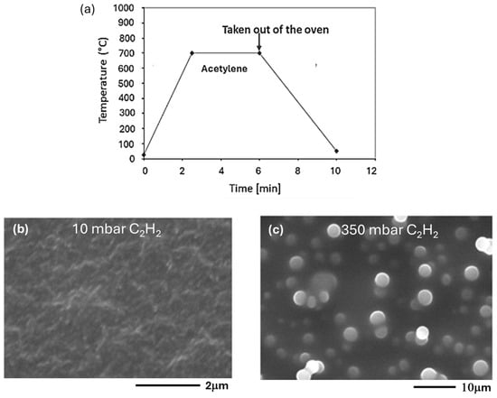
Figure 1.
(a) Chronograms of the operating parameters of synthesis (CCVD) on Co/SiO2/Si-catalyst and SEM images of the products obtained by injecting acetylene into the reactor at room temperature with an initial pressure of (b) 10 mbar and (c) 350 mbar.
After 6 min, the reactor was removed from the oven and cooled to room temperature, and the sample was analyzed. SEM analyses showed that by injecting acetylene into the reactor at room temperature and with a pressure of 10 mbar, only a few short nanotubes were evident (Figure 1b). A pressure of 350 mbar does not seem to be convenient for the synthesis of CNTs.
In fact, high resolution SEM images show (Figure 1c) amorphous carbon spheres similar to diamond-like carbon (DLC) [20,21]. The film composed of these spheres has similar characteristics of chemical inertness, thermal conductivity, and mechanical resistance that only diamond possesses, as reported in previous studies [21]. The pressure of 350 mbar is the initial pressure of acetylene at room temperature at the reactor inlet, but at 700 °C it becomes equal to 1140 mbar.
High pressure significantly affects the formation of carbon spheres rather than carbon nanotubes. This can be attributed to the higher thermodynamic stability of carbon spheres. In high-pressure environments, spherical structures are expected to be more stable than the open cylindrical structures of nanotubes.
2.1.2. The Role of the Initial Temperature of Acetylene Injected into the Reactor in Presence of Co/SiO2/Si
The influence of the initial temperature of acetylene inlet into the reactor on the synthesis of carbon nanotubes was also evaluated.
The images reported in Figure 2 show two different cases—where acetylene was fed into the reactor at room temperature (Figure 2a), and where it was injected when a temperature of 700 °C had already been reached in the reactor (Figure 2b). In both cases the pressure was 50 mbar. SEM images of the respective products show that in the first case a correct formation of carbon nanotubes does not occur (Figure 2c), while in the second case a large number of nanotubes are formed, as shown by the SEM image (Figure 2d).
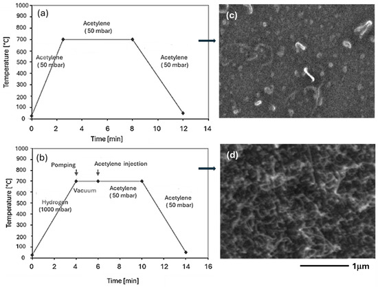
Figure 2.
Chronograms of the operating parameters of synthesis (CCVD) on Co/SiO2/Si-catalyst with acetylene injection (a) at room temperature and (b) at 700 °C in the reactor, and (c,d) SEM images of the respective products.
It can be stated that the introduction of acetylene at room temperature directly into the reactor leads to the deactivation of Co nanoparticles by forming a carbon layer that prevents further reaction.
2.1.3. The Role of Reaction Temperatures on the Morphology of Obtained Products in Presence of Co/SiO2/Si
The synthesis was carried out on the thin 30 Å sample at 600, 700, 800, and 900 °C using the injection of acetylene at reaction temperature and at 50 mbar pressure (Figure 3a). At 600 °C, only a small number of CNTs is formed; the catalytic activity of the Co nanoparticles is low (Figure 3b). With increasing temperatures (700 °C), high density of CNTs is obtained, and their diameter increases (Figure 3c). At 900 °C, considerably big spheres of pyrolytic carbon are detected (Figure 3d) [21,22]. The reaction temperature has a great influence on the formation of CNTs.
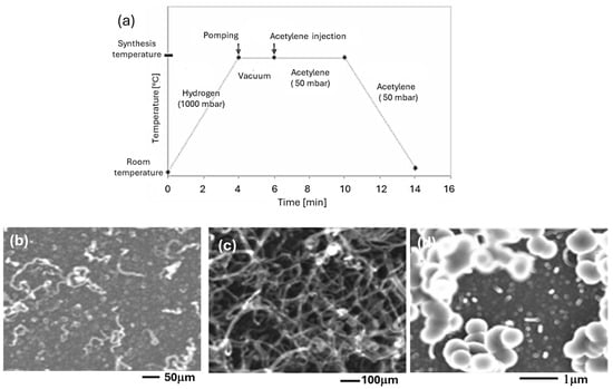
Figure 3.
(a) Chronograms of the operating parameters of synthesis (CCVD) on Co/SiO2/Si-catalyst and FE-SEM images of the products obtained at different synthesis temperatures: (b) 600 °C, (c) 700 °C, and (d) 900 °C.
At high temperatures, catalysts can undergo structural modifications or sintering, reducing their effectiveness. This can lead to the formation of pyrolytic carbon, as the active sites of the catalyst are no longer available for the orderly growth of carbon nanotubes. Additionally, at high temperatures, the amount of available carbon can exceed the catalyst’s capacity to manage it efficiently. This can result in the formation of pyrolytic carbon deposits, which cover the active sites of the catalyst and inhibit the growth of carbon nanotubes. Furthermore, at high temperatures, pyrolytic structures can be more thermodynamically stable than carbon nanotubes. This means that, in the presence of high temperatures, pyrolytic carbon can become the preferred form of carbon atom aggregation.
Particularly interesting are the products obtained at 800 °C that represent the limit for obtaining carbon nanotubes beyond which, as previously illustrated, spheres of pyrolytic carbon are obtained instead (Figure 3d).
Figure 4 shows FE-SEM images of the sample obtained at 800 °C. Figure 4a shows high density of carbon nanotubes, but the most important aspect is revealed by the transverse Fe-SEM image (Figure 4b) that shows straight tubes coming out of the surface.
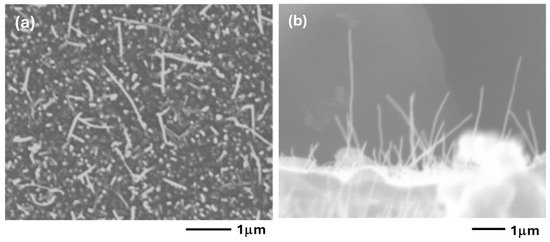
Figure 4.
Different views of FE-SEM images of the carbon nanotubes obtained at synthesis temperature of 800 °C: (a) top view and (b) section.
The presented data is crucial for the development of technological devices due to the uniqueness of carbon nanotubes (CNTs) obtained at a temperature of 800 °C.
High Density and Purity of Carbon Nanotubes: At the critical temperature of 800 °C, a structure with high-density carbon nanotubes is obtained. This feature is essential because high-density CNTs are highly sought after in high-efficiency devices, thanks to their superior conductive and mechanical properties.
Cross-Sectional and Straight Structure of Nanotubes: As highlighted by the cross-sectional FE-SEM image (Figure 4b), the carbon nanotubes appear straight and aligned. This aspect is crucial, as the linearity and orientation of the nanotubes significantly enhance their electronic and emission properties.
Field Emission Applications: The combination of a well-aligned, high-density structure makes these samples particularly suitable for field emission devices (FEDs). The straight nanotubes favor better electron emission efficiency, making this material an excellent candidate for flat-screen displays, lamps, and microwave devices.
The diameters of cobalt (Co) nanoparticles and carbon nanotubes (CNTs) were compared in relation to the synthesis temperature and reported in Table 1. The initial thickness of the catalytic support (Co/SiO2/Si) used was 30 Angstroms. The diameters were measured using Feret’s method.

Table 1.
Variation of the size of Co nanoparticles and of CNTs as a function of temperature of synthesis.
The Feret method, also known as the Feret diameter, is commonly used to analyze particle size. It is often applied in microscopy to measure the size of a three-dimensional object projected onto a two-dimensional plane.
In the case of cobalt (Co) nanoparticles and carbon nanotubes (CNTs), the Feret diameter is measured as the distance between two parallel tangents touching the perimeter of the particle’s projected area. This method is useful for characterizing the size and distribution of particles in a sample.
For CNTs synthesized at temperatures of 600 °C and 700 °C, the diameters correspond to those of the Co nanoparticles. However, CNTs synthesized at 800 °C have a larger diameter than the nanoparticles. This increase in diameter is attributed to the formation of a thick layer of amorphous carbon on the CNTs, as reported in reference [23].
2.1.4. Influence of Catalyst Thickness on Co/SiO2/Si
The influence of cobalt (Co) nanoparticle size on the diameter of carbon nanotubes (CNTs) was thoroughly examined using catalyst support with varying thicknesses: 20 Å, 30 Å, 40 Å, and 90 Å (Figure 5).
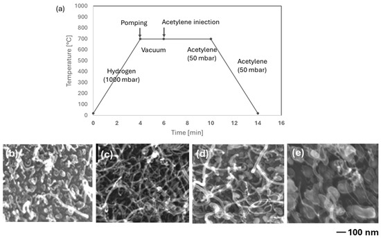
Figure 5.
Influence of cobalt deposit thickness on the morphology of carbon nanotubes: (a) chronograms of the operating parameters of synthesis (CCVD) on Co/SiO2/Si-catalyst. The images FE-SEM of carbon nanotubes obtained as a function of the thickness of the cobalt nanoparticle deposits: (b) 20 Å; (c) 30 Å; (d) 40 Å; and (e) 90 Å.
Table 2 further quantifies the relationship between Co nanoparticle size and CNT diameter, showing that the diameter of the CNTs increases with the particle size of the Co nanoparticles. This correlation underscores the importance of precise control over the catalyst thickness to achieve desired CNT characteristics.
Table 2.
Variation of the size of Co nanoparticles and of CNTs for Co films of various thicknesses (temperature of calcination and of reaction: 700 °C).
The diameter of carbon nanotubes (CNTs) is consistently larger than the size of the corresponding cobalt (Co) nanoparticles. This discrepancy is attributed to the deposition of amorphous carbon on the nanotubes. Among the samples, the CNTs obtained on the 30 Å sample stand out as the most suitable for further applications due to their relatively thin (16 ± 7 nm) and elongated structure (Figure 5c).
2.1.5. Influence of the SiO2 Characteristics of the Co/SiO2/Si Catalyst Support
The SiO2 coating serves a dual purpose. Firstly, it prevents the metallic cobalt (Co) from diffusing and reacting with the silicon crystal during the heating process. Secondly, it facilitates the formation of cobalt silicate, enhancing the adhesion of Co nanoparticles to the silica support.
To further investigate the role played by the SiO2 coating, two samples were compared: one with a commercial SiO2/Si support and the other with a thermally oxidized support. A thin 30 Å Co layer was deposited on each support.
Figure 6 shows the 30 Å film calcined for 12 min at 700 °C. The thermally oxidized sample is illustrated in Figure 6b,d, while the commercial sample is shown in Figure 6c,e. The commercial sample is characterized by much bigger Co particles.
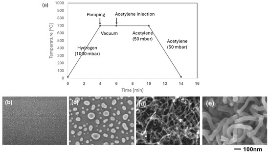
Figure 6.
(a) Chronograms of the operating parameters of synthesis (CCVD) on Co/SiO2/Si-catalyst (d,e). Influence of the thickness of SiO2 (b,c) on the size of Co nanoparticles; and (d,e) on the morphology of CNTs. (b,d): native oxide; (c,e) 220 nm SiO2.
Several samples, 30, 40, 60, and 90 Å samples produced on commercial support were treated by C2H2 using the CVD method at 700 °C. (Figure 7). The diameter of the CNTs is always bigger on the commercial sample compared to the thermally oxidized samples. For example, the CNT diameters of the 30 and 60 Å commercial samples are 30 ± 15 nm and 60 ± 10 nm, respectively (Figure 7a,c), and for the thermally oxidized samples, 16 ± 7 nm and 20 ± 8 nm, respectively (Figure 5).
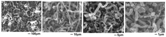
Figure 7.
FE-SEM images. Influence of the thickness of the Co film on the morphology of CNTs obtained by CCVD: (a) 30 Å, (b) 40 Å, (c) 60 Å, and (d) 90 Å.
In addition, the CNT carpet adhesion is very weak on the commercial substrate SiO2/Si. Indeed, the carpet is easily detached from the support and catalytic Co particles are detected at the ends of the nanotubes, i.e., tip-growth characterizes this sample (Figure 8).
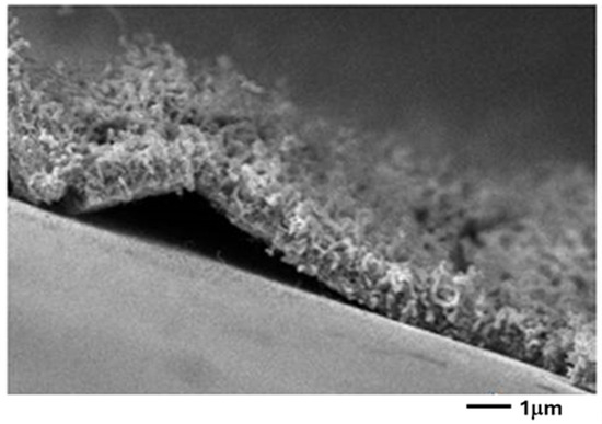
Figure 8.
FE-SEM image of the section of the sample shown in Figure 7c (60 Å of Co thickness). The film of the CNTs does not adhere properly to the substrate.
This occurs when the interaction metal support is weak, and the catalytic particle is lifted during the growth of the nanotube [24]. On the other hand, on the thermally oxidized samples, a layer of Co2SiO4 is formed as shown above [25,26]. The adhesion of the nanoparticles is thus enhanced, and a bottom-growth occurs, where the CNTs are sticking to the substrate. The influence of oxygen on the quality of the CNTs was also investigated. A total of 2 mbar of air was added to the 50 mbar of acetylene. The diameter of the CNTs decreased from 48 ± 7 nm (without air) to 29 ± 4 nm in the presence of air (Figure 9).
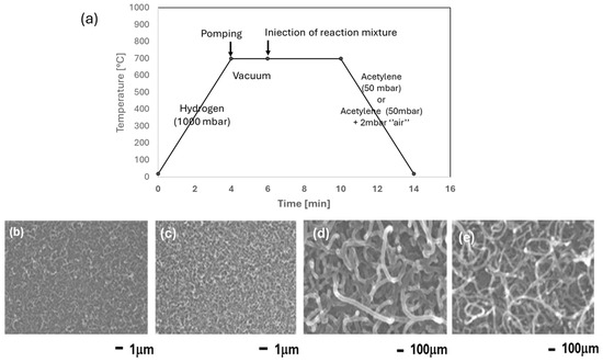
Figure 9.
(a) Chronograms of the operating parameters of synthesis (CCVD) on Co/SiO2/Si-catalyst. FE-SEM pictures illustrating the influence of oxygen on the morphology of CNTs. (b,c) pC2H2 = 50 mbar; (d,e) pC2H2 = 50 mbar + pair = 20 mbar.
The publications dealing with oxidative pretreatment are common [26,27,28], but the synthesis of CNTs in the presence of oxidant molecules is scarce. Lee et al. [29] have examined the effect of added oxygen on the synthesis of CNTs using PE-CVD on Ni/SiO2. Raman and TEM results have shown better quality of CNTs using a mixture of CH4/H2/O2 compared to the CH4/H2 mixture. The authors have shown the presence of OH* radicals that react faster with amorphous carbon and defects in the nanotubes. In our case, also, the presence of oxygen leads to the elimination of the amorphous carbon gain and, hence, much narrower nanotubes are obtained. All the pictures showing the morphology of the nanotubes were taken on a SEM instrument. Due to the thickness of the support + nanotubes layer, it is not possible to directly prepare samples for TEM measurements. That is why a method of scratching was adopted, consisting in scratching the CNTs above a carbon thin film or form var where the nanotubes are then deposited. Figure 10 shows the CNTs obtained on the 40 Å and 90 Å samples.
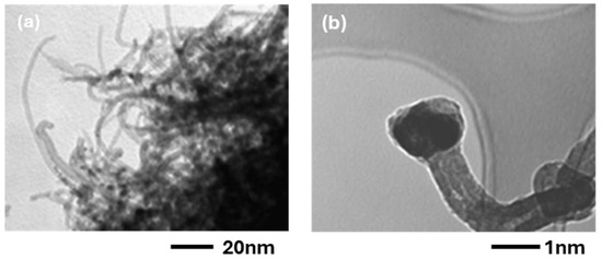
Figure 10.
TEM images of CNTs synthesized on (a) Co 40 Å and (b) Co 90 Å on Co/SiO2/Si catalysts.
The thin sample is characterized by narrow CNTs, and the tubes’ tips do not show the presence of catalytic Co particles. On the other hand, in the 90 Å sample some big fibers can also be found, suggesting a bamboo structure [30,31]. The diameter of the Co nanoparticles (two rows in Table 3) is compared with the diameter of the CNTs, obtained by FE-SEM and TEM results in both cases.
Table 3.
Diameter of Co particles and of CNTs synthesized on the 60 Å and 90 Å Co/SiO2/Si catalysts.
We can say that the two methods yield similar results. Moreover, the diameter of the CNTs is quasi equal to that of the Co nanoparticles, showing once again that the latter govern the diameter of the CNTs.
2.2. Co/C Nanoparticles
Yu et al. carried out the synthesis of CNTs on diamond-like carbon (DLC) [32]. They used plasma-enhanced chemical vapor deposition (PE-CVD) of acetylene. Following these authors, the field-emission of CNTs was enhanced. CNTs were also synthesized on Fe nanoparticles deposited on carbon fiber [33], or on CNTs [34]. CNTs were also obtained on weaved carbon fiber used as reinforcing component in epoxy or polyester [35].
2.2.1. Influence of the Initial Temperature of Acetylene in Presence of Co/C
The introduction of acetylene must be made at the reaction temperature of 700 °C. If it is introduced early, at room temperature, during the raising of the temperature only amorphous carbon is deposited on the Co particles (Figure 11a). In contrast, when acetylene is introduced at 700 °C, nice CNTs are obtained (Figure 11b).
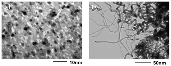
Figure 11.
Influence of the mode of injection of acetylene—(a) injection before heating, (b) injection at 700 °C—on a Co/C sample with 20 Å of Co deposit.
2.2.2. Influence of Synthesis Temperatures in the Presence of Co/C
The temperature of the synthesis is very important for obtaining the best possible CNTs. Figure 12 shows chronograms of the operating parameters of synthesis and the TEM pictures of the CNTs synthesized at 600, 700, and 800 °C (Figure 12b–d). At 600 °C and 700 °C, nice CNTs are formed, while at 800 °C only an amorphous carbon film is formed.
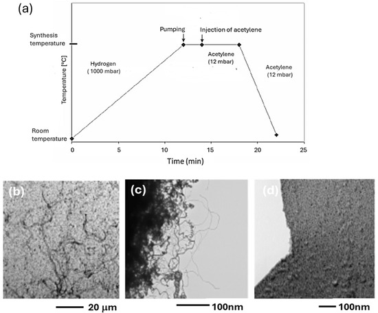
Figure 12.
(a) Chronogram of the operating parameters of synthesis (CCVD) on a Co/C sample with 20 Å of Co deposit. TEM images of the CNTs synthesized at various temperatures: (b) 600 °C, (c) 700 °C, and (d) 800 °C.
In the case of Ni/C, it was shown that Ni was reacting with the carbon film [36]. High temperature also favors the diffusion of transition metals, such as Fe, through the graphitic structure [33]. We can think that Co behaves similarly to Fe and Ni for the reactivity and diffusion through the carbon film. Lower temperatures were also tested to produce CNTs. Figure 13 shows CNTs obtained on the 20 Å Co/C sample at 450, 500, and 550 °C.
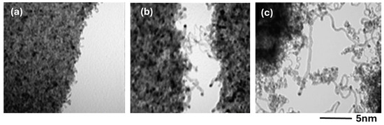
Figure 13.
TEM images of CNTs obtained by CCVD on a Co/C sample with 20 Å of Co deposit at various temperatures: (a) 450 °C, (b) 500 °C, and (c) 550 °C.
The TEM pictures were taken with great difficulty, because the external part of the CNTs coming out from the support was moving and vibrating continuously. At the lowest temperature, the nanotubes are short. Their length is increasing with increasing temperature, due to the increased reaction rate [37]. In addition, Co nanoparticles are also detected at the tips of the nanotubes, suggesting a tip-growth in this case. The influence of the thickness of the Co layer can easily be described. The results obtained on the 20 Å sample were already shown in Figure 12 and Figure 13. On the other hand, the 60 Å sample shows only a deposit of amorphous carbon on the big 50–100 nm Co particles. It is thus seen that the big particles do not lead to the formation of CNTs. The size of the CNTs was determined on the 20 Å sample, where the synthesis temperature was 550 °C. Figure 14 shows a bimodal distribution of the CNTs diameter.
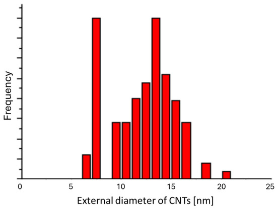
Figure 14.
Distribution of the external diameters of CNTs synthesized on the 20 Å sample at 550 °C.
The first one, a narrow distribution, is centered on 7 nm and corresponds to the size of Co nanoparticles, 9 ± 3 nm. The second one, a broad distribution, is centered on ca. 14 nm. The broad distributions due to the presence of amorphous carbon on the CNTs broaden the size of the nanotubes in a random manner.
3. Materials and Methods
3.1. Materials
For the synthesis of carbon nanotubes, two different catalytic supports with depositions of cobalt nanoparticles were used, which were already widely studied and described in our previous work [19]. In particular, the C support was made of conventional carbon grids used for the transmission electron microscope (TEM), deposited on copper grids (200 mesh or about 70 µm, from Agar Scientific, Essex, UK), while for the SiO2/Si support thermally oxidized silicon girdle cake was used. The latter was cut into 2 cm2 pieces. Scanning electron microscope (SEM), field emission electron microscope (FE-SEM) JEOL JSM 7401F (Tokyo, Japan), and transmission electron microscope (TEM)--Philips TECNAI 10 (Amsterdam, The Netherlands), were used.
3.2. Preparation of the Substrates
The carbon grids are very delicate, and they are not pretreated before use.
The silicon (100) girdle-cakes are spontaneously recovered by a thin oxide layer, when exposed to air. In order to increase this layer, we carried out a heat treatment under oxidative atmosphere for the commercial silicon girdle cakes.
Before the thermal oxidation, the silicon supports are carefully cleaned (3 × 20 min) with absolute ethanol using an ultrasound bath. The samples to be oxidized are placed into a quartz reactor where medical oxygen is introduced (4 sccm). The sample is flushed during 5 min at room temperature; then, the reactor is put in the center of the tubular furnace Carbolite at 1000 °C for 1h. After the treatment, the reactor is cooled down to room temperature in ca. 20 min under oxygen flow. That way, a thick oxide layer is formed on the silicon substrate. The deposition of cobalt nanoparticles is thoroughly illustrated in the previous paper [19]. Briefly, the deposition of cobalt nanoparticles on the two different supports was achieved through physical vapor deposition (PVD) using a 0.05 m3 magnetron followed by a reduction treatment in hydrogen atmosphere.
The choice of the Co film thickness of 20 Å for the Co/C sample and 30 Å for the Co/SiO2/Si sample was derived from preliminary investigations and considerations that evaluated the conditions for adequate interaction with the substrate.
The catalytic chemical vapor deposition (CCVD) synthesis of CNTs was carried out by the same dispositive used for the calcination of nanoparticles. Two quantities of acetylene were used to measure the difference in the yield of CNTs at 10 mbar and 350 mbar in C2H2, when T = 700 °C and the time of reaction of 6 min. The description of the experiments is shown in “chronograms” joined to each TEM result, where the different actions are reported as a function of time. In this work, experiments were carried out similar to those reported on Co/SiO2/Si samples. The operational conditions selected and adopted in this research are the result of preliminary investigations and careful evaluations. We sought a balance between the optimal conditions to achieve our objectives and the experimental availability of our laboratory.
4. Conclusions
In this research, two different catalytic supports, Co/SiO2/Si and Co/C, characterized by the presence of cobalt nanoparticles, were used, and the carbon nanotubes obtained through CVD synthesis were compared.
In summary, the most significant data obtained are as follows:
- -
- For synthesizing CNTs through CVD using acetylene as the carbon source, the hydrocarbon must be injected into the reactor at the reaction temperature. Otherwise, the Co nanoparticles are deactivated, and a layer of amorphous carbon surrounds the particle.
- -
- The optimal temperature for CNT synthesis on Co/SiO2/Si is 800 °C. For the Co/C support, the optimal temperature is 450 °C.
- -
- The optimal thickness of the Co layer is between 20 and 30 Å. For thinner layers, the CNTs density is very weak, while for thicker layers, short and deformed nanotubes and encapsulated nanoparticles are formed.
- -
- The CNTs synthesized on Co/SiO2/Si are well formed and aesthetically pleasing, while those formed on Co/C have a bamboo-like appearance.
- -
- The growth of CNTs occurs from the bottom on Co/SiO2/Si and from the top on the Co/C system.
It is important to emphasize that all these experimental data obtained are crucial for directing and conditioning the properties of carbon nanotubes, which can have a significant impact on a wide range of technological applications.
The ability to control the growth of CNTs is essential for obtaining uniform and well defined structures. The optimal conditions of temperature and thickness of the Co layer directly influence the morphology of CNTs, as demonstrated by the differences between CNTs on Co/SiO2/Si and those on Co/C. This control is fundamental to ensuring reliable performance in electronic devices.
The electronic properties of CNTs are closely linked to their structure. For example, well-formed and homogeneous CNTs, like those synthesized on Co/SiO2/Si, exhibit better conduction characteristics than deformed, bamboo-like CNTs. This makes CNTs on Co/SiO2/Si particularly promising for nanoelectronic applications, such as transistors and sensors.
The optimal experimental conditions also contribute to improving the efficiency and purity of the produced CNTs. The reaction temperature and hydrocarbon injection method can prevent the formation of amorphous carbon and ensure the formation of high-density, high-quality CNTs. This is important for reducing production costs and increasing the profitability of CNT-based technologies.
Achieving CNTs with desired properties paves the way for a wide range of applications. Besides nanoelectronics, CNTs can be used in high-strength composite materials, energy storage devices, advanced filters, and much more. The ability to manipulate the properties of CNTs through precise experimental conditions makes these technologies extremely versatile and promising.
In summary, optimizing the experimental conditions for CNT synthesis is crucial for unlocking their full technological and commercial potential. Understanding and controlling these factors, as highlighted in this research, allows for the development of carbon nanotubes with tailored properties for specific applications, accelerating scientific and innovative progress in many fields. This study represents a gradual approach that has enabled the optimization of the synthesis conditions. A more in-depth characterization of the obtained products, such as purity and electrophysical properties, is expected to be the subject of future studies.
A systematic comparison of the diameters, lengths, or other structural properties of carbon nanotubes (CNTs) could provide a solid basis for supporting observations about the effect of synthetic parameters. For example, it is well known that the size of CNTs can significantly influence their electrical, thermal, and mechanical properties. Evaluating how variations in synthesis parameters, such as temperature, growth time, or catalyst type, affect these dimensions and other structural characteristics would allow for a better understanding of the relationships between synthesis conditions and the final properties of CNTs. Future studies could therefore focus on these comparisons to further optimize synthesis conditions and enhance the performance of CNTs in their specific application fields.
Author Contributions
Conceptualization, J.B., N.M., J.D. and Z.M.; Methodology, J.B., N.M. and A.F.; Validation, J.B., D.V. and A.F.; Formal analysis, N.M.; Investigation, N.M., J.D. and Z.M.; Writing—original draft preparation, J.B., D.V. and P.D.L.; Writing—review and editing, D.V. and P.D.L.; Supervision, J.B., D.V. and P.D.L. All authors have read and agreed to the published version of the manuscript.
Funding
This research received no external funding.
Institutional Review Board Statement
Not applicable.
Informed Consent Statement
Not applicable.
Data Availability Statement
Data are contained within the article.
Conflicts of Interest
The authors declare no conflicts of interest.
References
- Iijima, S. Synthesis of carbon nanotubes. Nature 1991, 354, 56–58. [Google Scholar]
- Amelinckx, S.; Zhang, X.B.; Bernaerts, D.; Zhang, X.F.; Ivanov, V.; Nagy, J.B.; Lucas, A.A.; Lambin, P. A formation mechanism of catalytically grown helix shaped graphite nanotubes. Science 1994, 265, 635–639. [Google Scholar] [PubMed]
- Shoukat, R.; Khan, M.I. Carbon nanotubes: A review on properties, synthesis methods and applications in micro and nanotechnology. Microsyst Technol. 2021, 27, 4183–4192. [Google Scholar] [CrossRef]
- Dresselhaus, M.S.; Dresselhaus, G.; Saito, R. Physics of carbon nanotubes. Carbon 1995, 33, 883–891. [Google Scholar]
- De Luca, P.; Nappo, G.; Siciliano, C.; Nagy, J.B. The role of carbon nanotubes and cobalt in the synthesis of pellets of titanium silicates. J. Porous Mater. 2018, 25, 283–296. [Google Scholar]
- Yahyazadeh, A.; Nanda, S.; Dalai, A.K. Carbon Nanotubes: A Review of Synthesis Methods and Applications. Reactions 2024, 5, 429–451. [Google Scholar] [CrossRef]
- Tao, Z.; Zhao, Y.; Wang, Y.; Zhang, G. Recent Advances in Carbon Nanotube Technology: Bridging the Gap from Fundamental Science to Wide Applications. C 2024, 10, 69. [Google Scholar] [CrossRef]
- Shooshtari, M.; Salehi, A.; Vollebregt, S. Effect of Humidity on Gas Sensing Performance of Carbon Nanotube Gas Sensors Operated at Room Temperature. IEEE Sens. J. 2021, 21, 5763–5770. [Google Scholar] [CrossRef]
- Fonseca, A.; Pierard, N.; Tollis, S.; Bister, G.; Konya, Z.; Nagaraju, N.; Nagy, J.B. Hydrogen storage in carbon nanotubes produced by CVD. J. Phys. IV France 2002, 12, 129–137. [Google Scholar]
- Policicchio, A.; Vuono, D.; Rugiero, T.; De Luca, P.; Nagy, J.B. Study of MWCNTs adsorption performances in gas processes. J. CO2 Util. 2015, 10, 30–39. [Google Scholar]
- De Luca, P.; Siciliano, C.; Nagy, J.B.; Macario, A. The role of carbon nanotubes in the reactions of heterogeneous catalysis. Chem. Eng. Res. Des. 2023, 197, 74–84. [Google Scholar] [CrossRef]
- Birch, M.E.; Ruda-Eterenz, T.A.; Chai, M.; Andrews, R.; Hatfield, R.L. Properties that influence the specific surface areas of carbon nanotubes and nanofibers. Ann. Occup. Hyg. 2013, 57, 1148–1166. [Google Scholar] [PubMed]
- Morais, R.G.; Rey-Raap, N.; Costa, R.S.; Pereira, C.; Guedes, A.; Figueiredo, J.L.; Pereira, M.F.R. Hydrothermal carbon/carbon nanotube composites as electrocatalysts for the oxygen reduction. J. Compos. Sci. 2020, 4, 20. [Google Scholar] [CrossRef]
- Shah, K.A.; Tali, B.A. Synthesis of carbon nanotubes by catalytic chemical vapour deposition: A review on carbon sources, catalysts and substrates. Mater. Sci. Semicond. Process. 2016, 41, 67–82. [Google Scholar] [CrossRef]
- Nánai, L.; Németh, Z.; Kaptay, G.; Hernadi, K. Experimental and theoretical aspects of the growth of vertically aligned CNTs by CCVD on AZO substrate. Sci. Rep. 2024, 14, 7307. [Google Scholar] [CrossRef]
- Pant, M.; Singh, R.; Negi, P.; Tiwari, K.; Singh, Y. A comprehensive review on carbon nano-tube synthesis using chemical vapor deposition. Mater. Today Proc. 2021, 46, 11250–11253. [Google Scholar] [CrossRef]
- Lobo, L.S.; Carabineiro, S.A.C. Mechanisms of carbon nanotubes and graphene growth: Kinetics versus thermodynamics. C 2020, 6, 67. [Google Scholar] [CrossRef]
- Ürk, D.; Cebeci, F.Ç.; Öveçoğlu, M.L.; Cebeci, H. Structure-controlled growth of vertically-aligned carbon nanotube forests using iron–nickel bimetallic catalysts. Mater. Adv. 2021, 2, 2021–2030. [Google Scholar] [CrossRef]
- Moreau, N.; Fonseca, A.; Vuono, D.; Delhalle, J.; Mekhalif, Z.; De Luca, P.; Nagy, J.B. Physical Methods for the Preparation of Cobalt Nanoparticles for Use in the Synthesis of Multiwalled Carbon Nanotubes. Inorganics 2025, 13, 7. [Google Scholar] [CrossRef]
- Mendiara, T.; Domene, M.P.; Millera, A.; Bilbao, R.; Alzueta, M.U. An experimental study of the soot formed in the pyrolysis of acetylene. J. Anal. Appl. Pyrolysis 2005, 74, 486. [Google Scholar]
- Doi, I.; Haga, M.S.; Nagai, Y.E. Properties of DLC films deposited by an oxyacetylene flame. Diam. Relat. Mater. 1999, 8, 1682. [Google Scholar]
- Porwal, D.; Mukhopadhyay, K.; Ram, K.; Mathur, G.N. Investigation of the synthesis strategy of CNTs from CCVD by thermal analysis. Thermochim. Acta 2007, 463, 53. [Google Scholar]
- Escobar, M.; Moreno, M.S.; Candal, R.J.; Marchi, M.C.; Caso, A.; Polosecki, P.I.; Rubiolo, G.H.; Goyanes, S. Synthesis of carbon nanotubes by CVD: Effect of acetylene pressure on nanotubes characteristics. Appl. Surf. Sci. 2007, 254, 251–256. [Google Scholar]
- Hsu, C.M.; Lin, C.H.; Lai, H.J.; Kuo, C.T. Root growth of multi-wall carbon nanotubes by MPCVD. Thin Solid Films 2005, 471, 140. [Google Scholar]
- Joensson, C.T.; Maximov, I.A.; Whitlow, H.J.; Shutthanandan, V.; Saraf, L.; McCready, D.E.; Arey, B.W.; Zhang, Y.; Thevuthasan, S. Synthesis and characterization of cobalt silicide films on silicon. Nucl. Instrum. Methods Phys. Res. Sect. B 2006, 249, 532. [Google Scholar]
- Lee, K.H.; Baik, K.; Bang, J.S.; Lee, S.W.; Sigmund, W. Silicon enhanced carbon nanotube growth on nickel films by chemical vapor deposition. Solid State Commun. 2004, 129, 583–587. [Google Scholar]
- Yang, D.J.; Zhang, Q.; Yoon, S.F.; Ahn, J.; Wang, S.G.; Zhou, Q.; Wang, Q.; Li, J.Q. Effects of oxygen and nitrogen on carbon nanotube growth using a microwave plasma chemical vapor deposition technique. Surf. Coat. Technol. 2003, 167, 288–291. [Google Scholar]
- Minea, T.M.; Point, S.; Gohier, A.; Granier, A.; Godon, C.; Alvarez, F. Single chamber PVD/PECVD process for in situ control of the catalyst activity on carbon nanotubes growth. Surf. Coat. Technol. 2005, 200, 1101. [Google Scholar]
- Lee, H.; Kang, Y.S.; Lee, P.S.; Lee, J.Y. Hydrogen plasma treatment on catalytic layer and effect of oxygen additions on plasma enhanced chemical vapor deposition of carbon nanotube. J. Alloys Compd. 2002, 330–332, 569–573. [Google Scholar]
- Lu, Y.; Zhu, Z.; Su, D.; Wang, D.; Liu, Z.; Schlögl, R. Formation of bamboo-shape carbon nanotubes by controlled rapid decomposition of picric acid. Carbon 2004, 42, 3199–3207. [Google Scholar]
- Lee, C.J.; Park, J. On the diffusion-controlled growth of multiwalled carbon nanotubes. Carbon 2001, 39, 1891. [Google Scholar]
- Yu, W.; Zhang, J.; Liu, X.; Xi, W. Spinose carbon nanotubes grown on graphitized DLC film by low frequency r.f. plasma-enhanced chemical vapor deposition. Diam. Relat. Mater. 2003, 12, 2203–2207. [Google Scholar]
- Zhu, S.; Su, C.H.; Lehoczky, S.L.; Muntele, I.; Ila, D. Carbon nanotube growth on carbon fibers. Diam. Relat. Mater. 2003, 12, 1825. [Google Scholar]
- Xia, W.; Chen, X.; Kundu, S.; Wang, X.; Grundmeier, G.; Wang, Y.; Bron, M.; Schuhmann, W.; Muhler, M. Chemical vapour synthesis of secondary carbon nanotubes catalyzed by iron nanoparticles electrodeposited on primary carbon nanotubes. Surf. Coat. Technol. 2007, 201, 9232. [Google Scholar]
- Gong, Q.J.; Li, H.J.; Wang, X.; Fu, Q.G.; Wang, Z.W.; Li, K.Z. In situ catalytic growth of carbon nanotubes on the surface of carbon cloth. Compos. Sci. Technol. 2007, 67, 2986–2989. [Google Scholar]
- Gorbunov, A.; Jost, O.; Pompe, W.; Graff, A. Role of the catalyst particle size in the synthesis of single-wall carbon nanotubes. Appl. Surf. Sci. 2002, 197–198, 563–567. [Google Scholar]
- Chiu, C.C.; Tsai, T.Y.; Tai, N.H.; Lee, C.Y. Synthesis of Ultra Long Vertically Aligned Carbon Nanotubes Using the Rapid Heating and Cooling System in the Thermal Chemical Vapor Deposition Process. Surf. Coat. Technol. 2006, 200, 3215–3219. [Google Scholar]
Disclaimer/Publisher’s Note: The statements, opinions and data contained in all publications are solely those of the individual author(s) and contributor(s) and not of MDPI and/or the editor(s). MDPI and/or the editor(s) disclaim responsibility for any injury to people or property resulting from any ideas, methods, instructions or products referred to in the content. |
© 2025 by the authors. Licensee MDPI, Basel, Switzerland. This article is an open access article distributed under the terms and conditions of the Creative Commons Attribution (CC BY) license (https://creativecommons.org/licenses/by/4.0/).