Article

Encapsulating Ultrafine In2O3 Particles in Carbon Nanofiber Framework as Superior Electrode for Lithium-Ion Batteries

1
Key Laboratory of Microelectronics and Energy of Henan Province, Xinyang Normal University, Xinyang 464000, China
2
School of Materials Science and Engineering, Nankai University, Tianjin 300350, China
*
Author to whom correspondence should be addressed.
Inorganics 2024, 12(12), 336; https://doi.org/10.3390/inorganics12120336
Submission received: 26 November 2024 / Revised: 17 December 2024 / Accepted: 17 December 2024 / Published: 23 December 2024

Abstract

:
Indium oxide (In2O3) is a promising anode material for next-generation lithium-ion batteries and is prized for its high electrical conductivity, environmental friendliness, and high theoretical capacity. However, its practical application is significantly limited by severe volume expansion and contraction during the lithium insertion/extraction process. This volume change disrupts the solid electrolyte interphase (SEI) and degrades contact with the current collector, undermining battery performance. Although the nano-structured design of In2O3 can mitigate the volume effect to some extent, pure In2O3 nanomaterials are prone to agglomeration during frequent charging and discharging. The pure In2O3-based electrode shows a sustained and rapid capacity degradation. In this study, we embed ultrafine In2O3 particles in a carbon nanofiber framework using electrospinning and thermal annealing. The 1D carbon nanofiber structure provides an effective electronic conductive network and reduces the length of lithium-iondiffusion, which enhances the reactivity of the nanocomposite and improves electrode kinetics. Additionally, the carbon nanofiber framework isolates ultrafine In2O3 particles, preventing their aggregation. The small volume changes due to the ultrafine size of the In2O3 are buffered by the carbon materials, allowing the overall structure of the In2O3/C composite nanofiber to remain largely intact without crushing during charging and discharging cycles. This stability helps avoid electrode fracture and excessive SEI growth, resulting in superior cycle and rate performance compared with the pure In2O3 nanofiber electrodes.

1. Introduction

In recent years, stimulated by various preferential policies, the global energy landscape has undergone significant changes; new renewable energy sources, such as solar energy, wind energy, and tidal energy, are rapidly developing and partially replacing the market of fossil energy. However, limited by various factors such as weather, climate, geography, etc., the power generated by these new renewable energy sources is unstable; thus, supporting energy storage technologies should also be supplied to ensure the sustainable development of the new energy industry. Among them, lithium-ion batteries play a key role in large-scale energy storage due to their high energy density, environmental friendliness, and long lifespan [1,2,3,4,5,6,7].
As typical secondary rechargeable batteries [8,9,10,11,12,13], lithium-ion batteries (LIBs) have been widely investigated in view of their rocking chair working principle [14]. During the charging process, lithium ions from the positive electrode migrate to the negative electrode through the separator inside the battery, while the corresponding electrons from the positive electrode are transferred to the negative electrode through the external circuit. In the discharge process, ions and electrons return to the negative electrode through the battery’s internal separator and outer circuitry, respectively. The performance of a battery is mainly determined by its positive and negative electrode materials, and the commonly used commercial positive electrode materials are mainly transition metal oxides and phosphides containing lithium. For the negative electrode, the current commercially available material is graphite, which has low and stable lithium insertion/extraction working potential; however, the theoretical capacity of graphite is only 372 mAh g−1, and such a low actual capacity greatly limits the overall performance improvement of lithium-ion batteries; thus, both academia and enterprises are developing high-capacity negative electrode materials to meet urgent increasing needs.
Various novel negative electrode materials have been intensely explored, including intercalation-type materials (Li4Ti5O12, TiO2) [15,16,17], transition metal oxides (TiO2, NiO, Fe3O4, CoO) [18,19,20,21,22,23,24,25,26], or sulfides (Ni3S2, CoS, MnS) [27,28,29,30,31], which can store lithium via a conversion reaction mechanism. The typical electrochemical reaction equation is MN + Li ⟷ M + LiN, where M is a transition metal and N is O or S, the theoretical reversible capacity > 600 mAh g−1; however, these transition metal-based negative electrode materials suffer high hysteresis voltage in the charge/discharge process, and the corresponding lithium extraction working platform ranges from 1.0 to 2.5 V vs. Li/Li+. Such a high working potential will lower the output voltage and energy density of the full battery. On the contrary, many group 3, 4, and 5 elements like Ga, In, Si, Ge, Sn, and Sb [32,33,34,35,36] can reversibly form alloys with lithium at a relatively low working platform (0.1–1.0 V vs. Li/Li+) and high theoretical capacity (600–4200 mAh g−1); despite the tempting advantages, these electrode materials have insufficient reactivity when alloying with lithium; as a result, the actual capacity is far below the theoretical value, and the rate performance is rather poor.
On the other hand, group 3–5 element-based oxides (GeO2 [37], In2O3, SiO, SnO, SbO) [38,39] not only retain a low alloying potential, but also exhibit relatively high electrochemical reactivity; among them, In2O3 has aroused increasing interest in consideration of it environmental friendliness, high electrical conductivity, and high theoretical reversible capacity (580 mAh g−1 when In2O3 holds 4 Li, 965 mAh g−1 when In2O3 holds 10 Li) [40,41]. Nevertheless, despite the significant advantages mentioned above, the practical application of In2O3 as a negative electrode is largely limited by the severe volume expansion/contraction in the repeated lithium insertion/extraction process; such volume change cracks the formed SEI (solid electrolyte interphase, which originates from the irreversible decomposition of organic electrolytes on the surface of active materials) layer; thus, part of the active material is re-exposed in the electrolyte and induces the repeated growth of SEI, and the unstable SEI growth hinders the diffusion rate of lithium ions; even worse, some active materials are forced to detach from the current collector, leading to low Coulombic efficiency, rapid capacity degradation, and unsatisfactory rate performance of the bulk material-based electrodes.
Multiple strategies have been proposed to respond to the aforementioned challenges. The primary measure is to design various In2O3 nanomaterials such as nanoparticles, nanosheets, and nanospheres [42,43,44,45]; nanostructured materials with high specific surface area not only provide a large number of electrochemical reaction sites, but also greatly reduce the diffusion distance of lithium ions. Moreover, the rich pore volume of nanomaterials buffers the volume change and relieves the electrode stress. To sum up, the In2O3 nanomaterial-based electrodes exhibit superior electrochemical lithium storage performance compared with bulk-based electrodes. However, the free energy of the nanostructured sample is much higher than that of the bulk sample; thus, in order to maintain the stability of the system, nanostructured In2O3 tends to spontaneously aggregate during repeated charge and discharge processes [46]. As a consequence, the corresponding electrochemical performance significantly decreases when the initial nanostructure is gradually destroyed after dozens of cycles.
Regarding this issue, researchers have introduced a variety of foreign materials (metal, carbon, or metal oxide) [47] to composite with nanostructured In2O3 to further improve its electrochemical performance. Typical carbon materials like graphene and conducting polymers have a relatively high elastic modulus and appropriately accommodate stress caused by volume effects. Nevertheless, the low proportion of carbon coating on In2O3 nanomaterial cannot maintain its structure in long-term cycling; on the other hand, the high proportion of carbon coating will lower the overall specific capacity of the In2O3/C compound. Thus, it is still a challenge an achievement of highly dispersed In2O3/C nanocomposites to maintain a durable and stable electrode structure in the repeated lithium insertion/extraction reactions.
Herein, ultrafine In2O3 particles are uniformly embedded inside the carbon nanofiber framework via electrospinning and thermal annealing. Firstly, the 1D carbon nanofiber supplies a good electronic conductive network and lowers the diffusion length of lithium ions, which is beneficial for enhancing the reactivity of the nanocomposite and improving electrode kinetics. Secondly, the ultrafine In2O3 particles are isolated by the carbon nanofiber framework, preventing In2O3 nanoparticles from aggregating with each other. Thirdly, the relatively small volume change caused by the ultrafine size of indium oxide is buffered by carbon materials, the overall structure of the In2O3/C composite nanofibers remains largely intact without crushing during the charge and discharge processes, avoiding the electrode fracture and excessive growth of the SEI layer. Therefore, the In2O3/C composite nanofibers electrode exhibits superior cycle performance and rate performance compared with the pure In2O3/C nanofiber electrode.

2. Results and Discussion

Figure 1 presents the morphological characterization of the In2O3 nanofibers sample, which was prepared via calcining the precursor of the electrospinning product at a high temperature in an air atmosphere. From the SEM images (Figure 1a,b), we can see randomly distributed In2O3 nanofibers of 1~2 microns in length and 100~200 nanometers in diameter. From the TEM images (Figure 1c,d), one can clearly see that the rough In2O3 nanofiber is composed of a large number of nanoparticles, which are proved to be highly crystalline In2O3 by HRTEM observation in Figure 1e. Moreover, several clear selected area electron diffraction rings (SAED, Figure 1f) confirm that the nanofiber sample is polycrystalline. No carbon material can be examined inside the nanofiber because the PVP carbon source is calcined and decomposed in air.
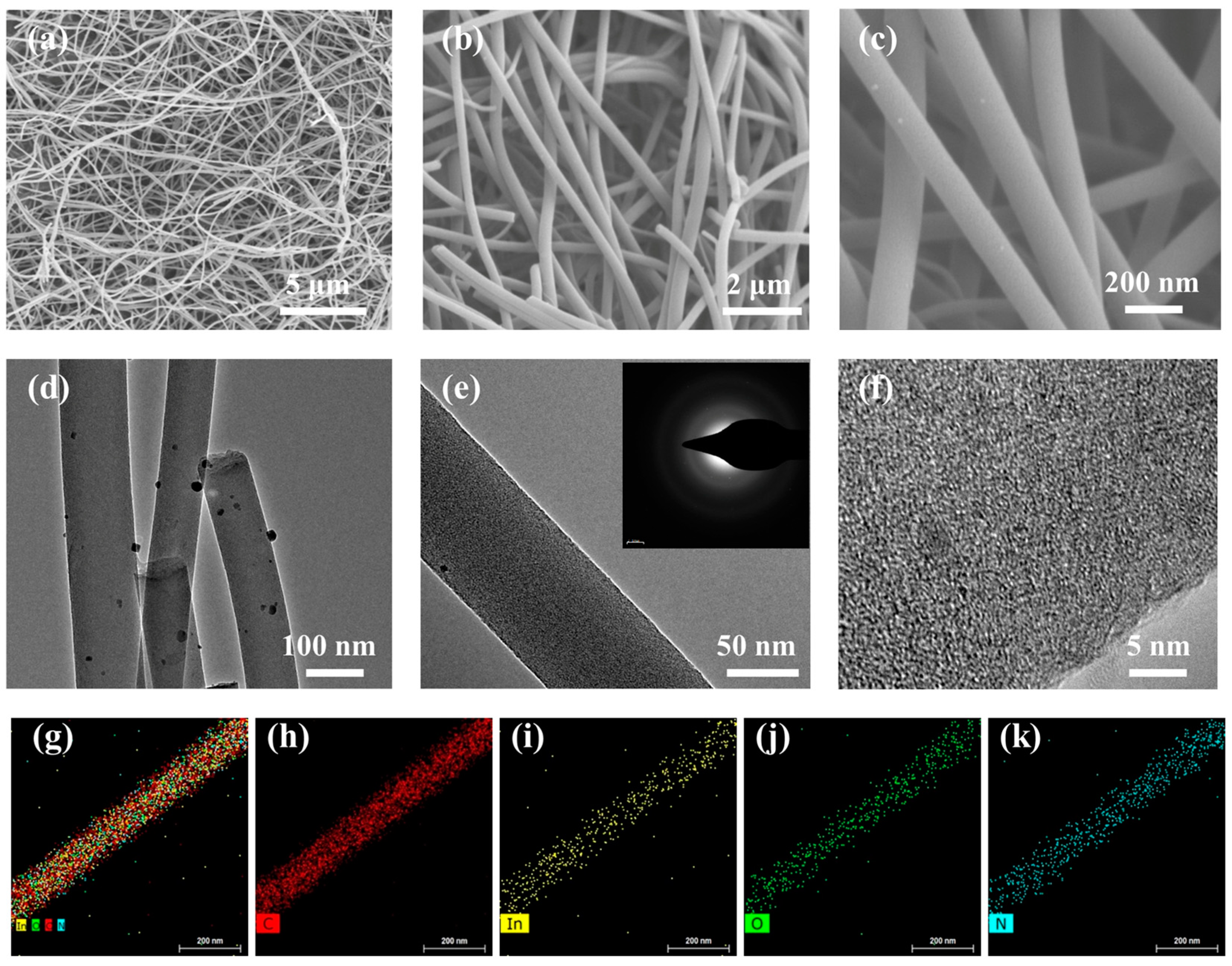
The comprehensive morphological characterization of prepared In2O3/C composite nanofibers is displayed in Figure 2. From the low magnification SEM image (Figure 2a), we can see that a large number of nanofibers are interwoven together with a length exceeding 10 microns, which is much longer than pure In2O3 nanofibers (in Figure 1a); the relatively long fiber scale indicates that In2O3/C composite nanofibers have higher strength and can resist mechanical strain during the annealing process; therefore, the high stress of active materials can also resist stress caused by volume changes during the lithiation/delithiation process [48,49]. From the enlarged SEM images in Figure 2b,c, one can see that the surface of In2O3/C composite nanofibers is relatively smooth compared with the In2O3 nanofibers sample; the smooth surface is due to the fact that numerous tiny In2O3 particles are embedded inside the nanofibers framework during the annealing process in an argon atmosphere, and such a structure reduces the size of active In2O3. Moreover, the carbon framework prevents the aggregation of In2O3 and helps maintain the integrity of the electrode during cyclic testing. A more detailed morphological structure is observed by the TEM image in Figure 2d–f; no obvious particles can be examined inside the composite nanofibers, proving that tiny In2O3 particles are highly dispersed in the carbon framework. Additionally, the relatively blurry SAED rings (the insert in Figure 2e) indicate the low crystallinity of In2O3 particles in the composite nanofibers, which is consistent with the SEM and TEM characterization results. In addition, Figure 2g–k present the element mapping of a single composite nanofiber, from which one can see that In, C, N, and O elements are uniformly dispersed in the In2O3/C composite nanofibers sample.
Figure 3a records the X-ray diffraction (XRD) patterns of the prepared In2O3 nanofiber and In2O3/C composite nanofiber samples; the main diffraction peaks of the two nanofiber samples match well with cubic In2O3 (JCPDS 06-0416); on the other hand, the diffraction peaks of the In2O3/C composite nanofibers sample is wider than that of the pure In2O3 nanofibers sample, implying the smaller size and lower crystallinity of In2O3 in the composite nanofibers, which is in good agreement with the above SEM and TEM research results. Furthermore, no obvious diffraction peaks of carbon material can be examined from the XRD patterns, indicating that the carbon material is highly amorphous in the In2O3/C composite nanofibers. Meanwhile, the detailed surface composition of In2O3/C composite nanofibers is studied using X-ray photoelectron spectroscopy (XPS); from the full XPS spectrum curve in Figure 3b, we can clearly see the presence of In, O, C, and N elements in the sample; these four detected elements are completely consistent with the TEM element mapping results. The high-resolution XPS spectrum of In 3d shows two adjacent peaks at about 454.6 and 445.0 eV, which corresponds to In 3d3/2 and In 3d1/2 of In4+, respectively. Moreover, according to the fitting results in Figure 3c, we can see the precise C 1s peak can be fitted into four peaks with bonding energies at 284.7, 285.4, 286.3, and 287.6 eV, which correspond to the C-C, C-N, C-O, and O-C=O groups, respectively. The precise N 1s (Figure 3e) peak consists of graphitic N (at about 400.4 eV), pyrrolic N (at about 399.0 eV), and pyridinic N (at about 398.4 eV). Significantly, the high-resolution O 1s peak is composed of a large proportion of O-In and a small amount of C-O, C=O groups. Thus, on the basis of the above characterizations and analysis, we can conclude that C, N, and a small amount of O elements originate from the PVP binder, while In and the remaining O elements originate from the indium oxide particles.
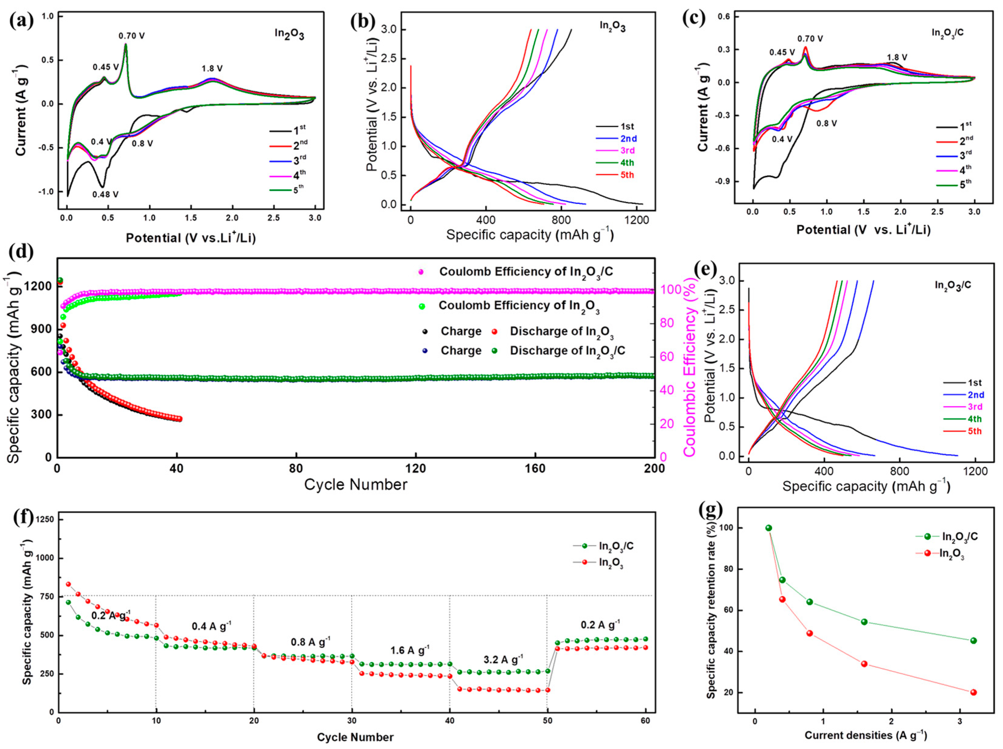
A series of electrochemical tests were conducted to evaluate the lithium storage performance of the two kinds of nanofiber electrodes. Figure 4a,c present the CV curves of the In2O3 nanofibers and In2O3/C composite nanofibers electrode at a scan rate of 0.2 mV s−1 for the initial five cycles, respectively. These two electrodes exhibit similar but distinct profiles; they both deliver a prominent broad peak at about 0.48 V in the first reduction scan curve, which is mainly related to the generation of the SEI layer. Two obvious reduction peaks at about 0.8 and 0.4 V can be recorded in the next reduction scan curves, which correspond to the conversion reaction (In2O3 + 6Li ⟶ 2In + 3Li2O) and alloying reaction (In + xLi ⟶ InLix), respectively. Notably, during the subsequent anodic scan process, the two nanofiber electrodes deliver two significant oxidation peaks at 0.45 and 0.70 V, which can be attributed to the gradual dealloying reaction of the indium lithium alloy (InLix⟶ In + xLi) [42,47]. In addition, the higher anodic peaks (range from 1.0–2.0 V) correspond to the part oxidation of In to In2O3 (2In + 3Li2O ⟶ In2O3 + 6Li) [40]. Based on the peaks position analysis above, the electrochemical lithium storage reactions process can be summarized as follows:
In2O3 + 6Li ⟶ 2In + 3Li2O
In + xLi ⟷ InLix
It should be emphasized that the In2O3/C composite nanofibers electrode exhibits weaker oxidation-reduction peaks compared to the In2O3 nanofibers electrode; such a phenomenon is mainly due to the fact that the carbon nanofiber framework prevents direct contact between lithium and In2O3 in the In2O3/C nanofibers electrode. The corresponding typical charge–discharge profiles of the In2O3 nanofiber and In2O3/C composite nanofiber electrodes are demonstrated in Figure 4b,e, respectively. The initial discharge capacity of these two electrodes is significantly higher than their charge capacity; the large irreversible capacity is mainly due to the irreversible decomposition of the electrolyte into the SEI layer. Moreover, the In2O3/C composite nanofibers electrode delivers a weaker charging and discharging platform compared with the In2O3 composite nanofibers electrode, which is consistent with the CV testing and analysis. The detailed cycling performance and Coulombic efficiency of the two electrodes at a constant current of 0.3 A g−1 are plotted in Figure 4d; it can be seen that the In2O3/C composite nanofiber electrode’s (olive dots) capacity tends to stabilize after several cycles; the delivered reversible capacity is 571 mAh g−1 after 200 charge/discharge cycles. On the other hand, the In2O3 nanofibers electrode (red dots) undergoes a sustained and rapid decay; its corresponding reversible capacity is only 269 mAh g−1 after 40 charge/discharge cycles.
Moreover, by observing the upper part of Figure 4d, we can see that the measured Coulombic efficiency of the In2O3/C composite nanofibers electrode (purple dots) is higher than that of the In2O3 nanofibers electrode (green dots), indicating that the In2O3/C composite nanofibers have a more stable SEI layer and superior reversible lithium storage capabilities compared with the In2O3 nanofibers sample.
In order to further compare their rate performance, the two nanofiber electrodes were tested at different current densities as shown in Figure 4f; the measured average reversible capacities of the In2O3/C composite nanofibers electrode are 544, 423, 365, 312, and 264 mAh g−1 at current densities of 0.2, 0.4, 0.8, 1.6, and 3.2 A g−1, respectively. In contrast, the delivered capacities of the In2O3 nanofibers electrode are 663, 457, 344, 244, and 148 mAh g−1 at the same test current densities. The In2O3/C composite nanofiber electrode’s capacity can restore to 470 mAh g−1 when the current density is set back to 0.2 A g−1. By contrast, the recovery capacity of the pure In2O3 nanofibers electrode is only 418 mAh g−1. In addition, the average capacity retention rates vs. current densities of the two nanofiber electrodes are recorded in Figure 4g; the reversible capacity retention rates of the In2O3/C composite nanofibers electrode are 100%, 78%, 67%, 57%, and 48% at 0.2, 0.4, 0.8, 1.6, and 3.2 A g−1; the corresponding capacity retention rates of the In2O3 nanofibers electrode are 100%, 69%, 51%, 37%, and 22%. Thus, based on the above electrochemical testing and some recent reported In2O3 and carbonaceous materials in Table 1, we can conclude that the In2O3/C composite nanofibers electrode has better cycling stability and rate performance compared with the In2O3 nanofibers electrode.
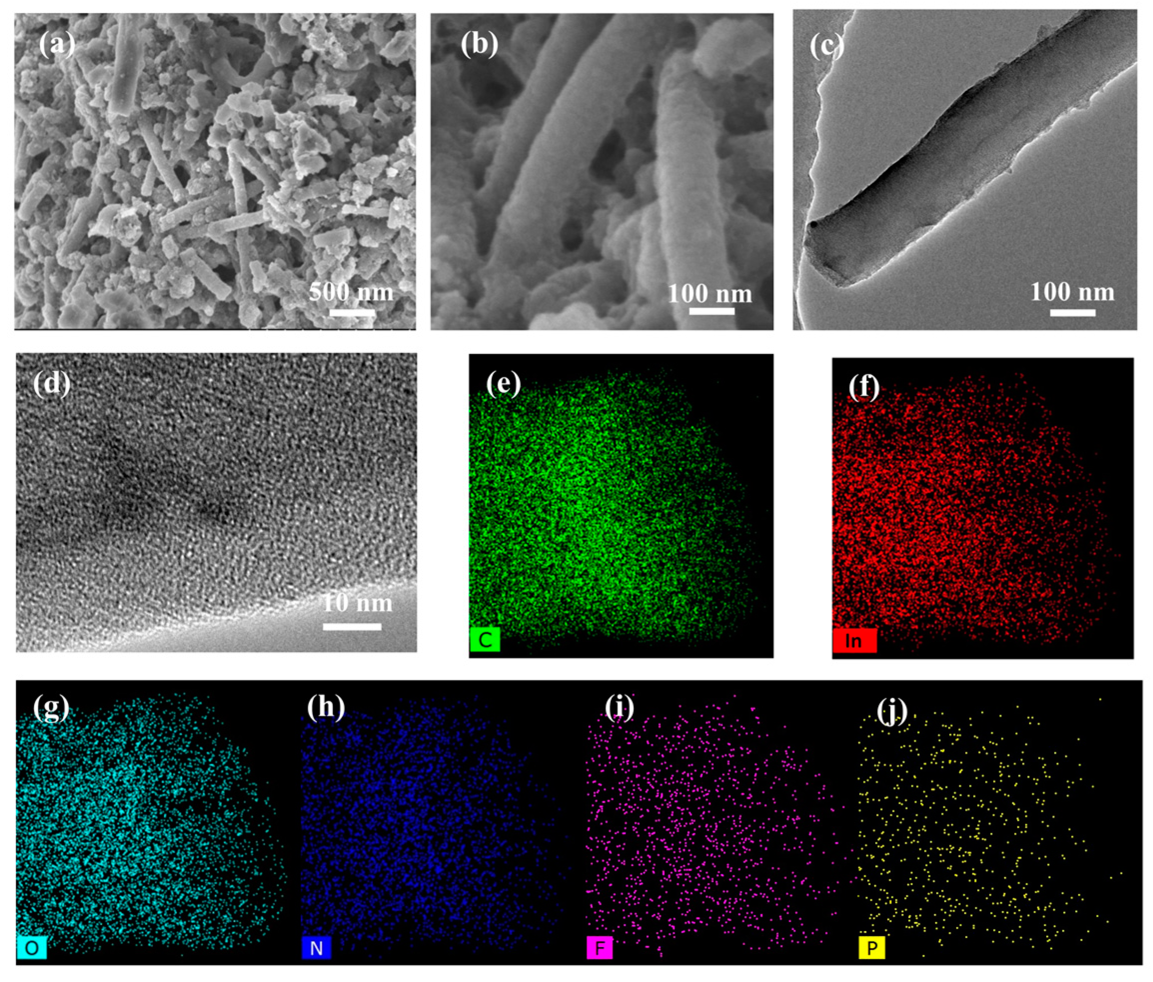
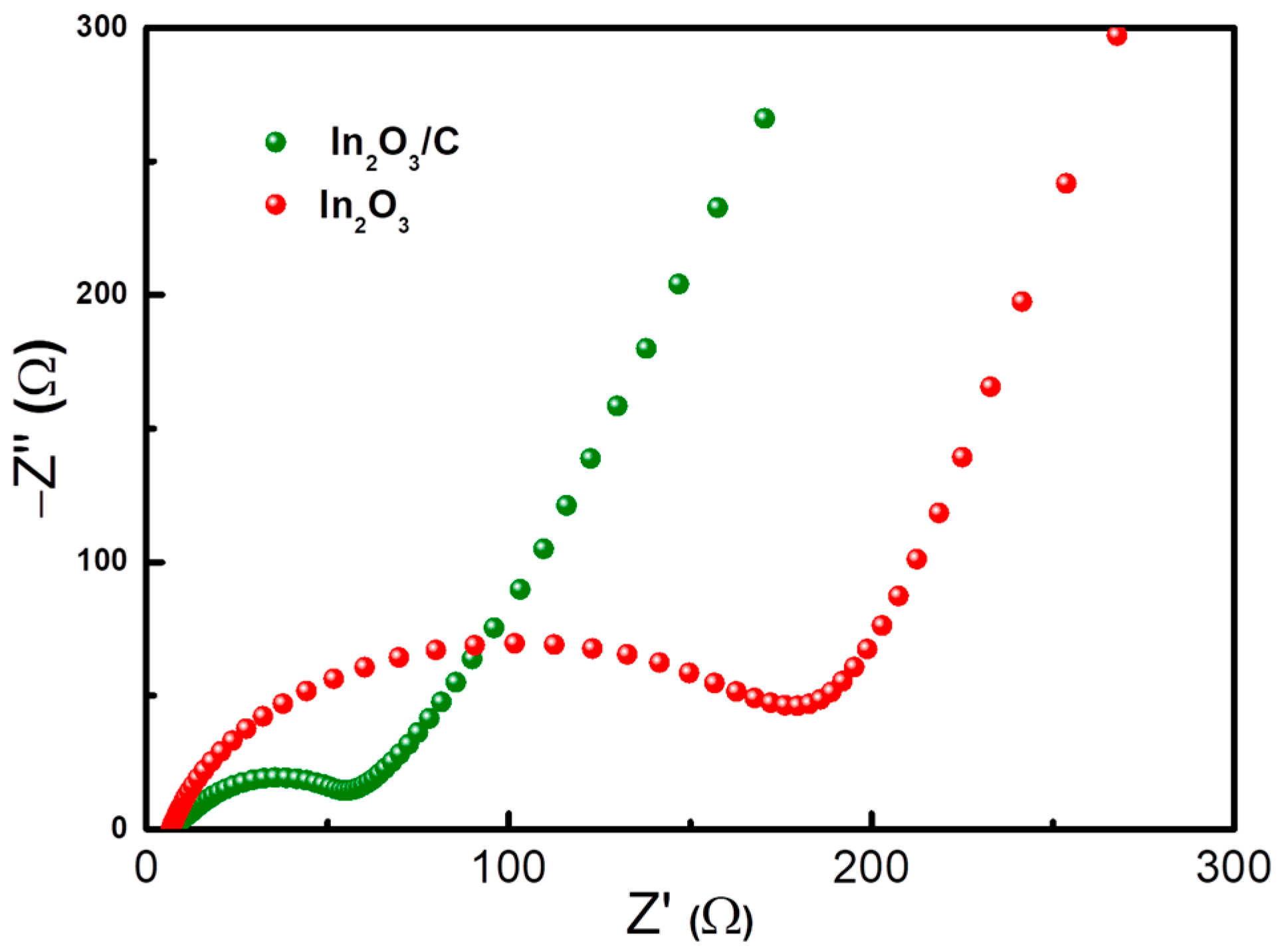
In order to better reveal the excellent lithium storage mechanism of the In2O3/C composite nanofibers, the cycled cells were put back into the glove box and disassembled to remove the working electrode. After washing away the residual electrolyte with propylene carbonate solvent, the cycled In2O3/C nanofibers sample was characterized as shown in Figure 5. From the SEM images in Figure 5a,b, we can see that the sample after cycling still maintains its typical nanofiber structure; moreover, the enlarged TEM images in Figure 5c,d demonstrate that the composite nanofibers have become rougher after cycling, which is mainly due to the formation of the SEI layer. Moreover, the element mapping demonstrates the existence of the In, C, O, N, F, and P elements of the cycled In2O3/C nanofiber (Figure 5e–j); compared with the pristine sample element mapping in Figure 2, the appearance F and P elements (Figure 5i,j) comes from the SEI layer, which involves the reversible decomposition of the LiPF6-based electrolyte. On the whole, the In2O3/C nanofibers can buffer stress changes during the charging and discharging process. In addition, Electrochemical impedance spectroscopy (EIS) of In2O3/C composite nanofiber and pure In2O3 nanofiber electrodes after cycling is shown in Figure 6; the Nyquist data consist of a semicircle (at the high-medium frequency region) and a line (at the low frequency region); we can see that the Rct (charge transfer, which can be obtained from the intercept of the semicircle on the X-axis) values of the In2O3/C composite nanofibers electrode and the In2O3 nanofibers electrode are about 58.5 and 205.5 Ω, respectively. The smaller resistance indicates that the In2O3/C composite nanofibers electrode possesses superior kinetics compared with the In2O3 nanofibers electrode.

3. Materials and Methods

3.1. Synthesis of Sample

The present indium oxide-based nanofibers were prepared by typical electrostatic spinning technology and thermal annealing process; the first step mainly involves preparing a suitable spinning gel solution; a primary, 1.2 g polyvinylpyrrolidone (PVP, purchased from Sigma Aldrich, Steinheim, Germany) polymer with molecular weight of 1,300,000 was mixed into 8 g N,N-dimethylformamide solvent (DMF, purchased from Innochem, Beijing, China); the mixed solution was continuously stirred by magnetic force for about 4 h until the binder was completely dissolved; then, 0.6 g In(NO3)3·H2O (purchase from Innochem, Beijing, China) was placed in the mixed solution; the electrospinning precursor solution was finally prepared when the mixed solution was further stirred to form a uniform viscous gel.
The second step was to convert the precursor gel solution into nanofibers via electrospinning technology. The obtained precursor gel solution was inhaled into a 5 mL plastic injection coupling with stainless steel needle; the inner diameter of the stainless steel needle was about 0.5 mm. The plastic injection filled with precursor gel solution was loaded on an electrospinning machine (WL-2, Beijing Aibo Zhiye Ion Technology Limited Company, Beijing, China), the gel solution was evenly pushed out from the syringe by the propeller with speed about 1.5 mL per hour, and the stainless steel needle was connected with the high-voltage positive wire of the power supply with a positive voltage of 13.5 kV. The gel solution coming out of the needle was stretched into nanofibers under the action of a strong electric field during the electrospinning process; simultaneously, the rapid DMF solvent evaporation lead to nanofiber solidification, the electrospinning nanofibers product was collected by a grounded drum with a rotation speed of 40 revolutions per minute, the straight-line distance between the stainless steel needle tip and the drum was approximately 13 cm, and the temperature and humidity inside the electrospinning machine were about 30 °C and 40%, respectively.
When the gel solution was completely exhausted, the electrospinning product was carefully peeled off from the drum. Immediately, the product was placed in an 80 °C oven for 6 h to dry the adsorbed water and residual solvents; after that, the sharped electrospinning nanofibers sample was placed in a 260 °C muffle furnace in air for about 4 h; the relatively low oxidation temperature is sufficient to oxidize indium nitrate but does not completely calcine the PVP carbon source. Finally, the pre-oxidized nanofibers sample was put into a tube furnace filled with argon atmosphere at 600 °C for 4 h; such relatively high temperature is sufficient to carbonize PVP without reducing indium oxide. Thus, In2O3 and carbon materials were in situ compounded in the nanofibers. As a comparison, the In2O3 nanofibers sample was obtained by calcining the pre-oxidized nanofibers in air at 600 °C for 4 h to completely remove the PVP carbon source.

3.2. Material Characterization

The composition of the obtained sample was examined using X-ray diffraction equipment (XRD, Rigaku D/Max-2400 diffractometer, Tokoy, Japan); the wavelength of the incident electromagnetic wave is 0.15406 nm, which originates from the transition from L layer electrons to K layer electrons in metallic copper. The diffraction angle of the sample was set between 10 and 80° with a scanning speed of 5° min−1. The detailed sample elemental composition, chemical valence, and bonding energy were studied by X-ray photoelectron spectroscopy (XPS, Kratos AXISUltra DLD, Manchester, UK); the photoelectrons were generated by the transition of electrons from the L layer to the K layer in aluminum metal, the corresponding energy was 1486.6 eV, the sample testing was conducted in a high vacuum environment, and XPS Peak software was applied to fit the high-resolution spectra.
The precise microstructure of the sample was characterized by field-emission scanning electron microscopy (FE-SEM, S-4800, Hitachi, Tokoy, Japan) and FEI transmission electron microscopy (TEM, FEI, Tecnai G2 F20, Waltham, MA, USA). In order to conduct SEM observation, the prepared nanofibers sample was adhered on a metal tray with conductive adhesive. To prepare the TEM observation, a small amount of the nanofibers sample was sonicated and dispersed in an alcohol solvent for about 10 min; subsequently, a dropper was applied to extract the mixed solution and drop it onto a microgrid; after drying the residual alcohol, the microgrid was sent into the sample chamber for vacuum pumping.

3.3. Cell Preparation and Testing

The electrochemical lithium storage performance of prepared In2O3 nanofibers and In2O3/C composite nanofibers were investigated by assembling half cells. The working electrodes were fabricated via the conventional slurry approach. Briefly, the active materials of the nanofibers sample, acetylene black (as a conductive agent) and sodium alginate (as a binder), were accurately weighed with mass ratio of 8:1:1; these three components were manually ground and mixed in an agate mortar for about 1 h, and then an appropriate amount of deionized water was added to the mixture and continuously stirred to form a viscous slurry, which was evenly coated on the surface of copper foil by a scraper. After drying the deionized water solvent in a vacuum oven, the coated copper foil was sliced into small circular pieces with a diameter of 12 mm as working electrodes.
Next, the cells were assembled in a glove box (Etelux, Beijing, China) filled with inert gas atmosphere (the concentration of argon gas is higher than 99.9%); the prepared working electrode, glass fiber (as a separator), lithium metal foil (as a reference electrode and counter electrode), stainless steel gasket, and spring sheet were sequentially placed into the positive electrode shell; subsequently, approximately 120 μL of organic electrolyte (1 M LiPF6 dissolved in ethylene carbonate (EC) and dimethyl carbonate (DEC)) was dropped into the cell, and then the negative electrode shell was placed on top of the positive electrode case. Finally, the two sides of the cells were sealed using a hydraulic press. In order to allow the electrolyte to fully infiltrate the battery system, the assembled cells were taken out of the glove box and aged for about 24 h; the open circuit voltage of these half cells was approximately 2.0–3.5 V. The cycling and rate performance of the batteries were evaluated on a battery testing channel (BTS-610, Neware, Shenzhen, China). The corresponding cyclic voltammetry (CV) was conducted on electrochemical workstation (CHI-660E, Chenhua, Shanghai, China), Electrochemical impedance spectroscopy (EIS) was carried out in the frequency range of 0.01–100,000 Hz with an applied perturbation voltage of 5 mV, and all of these electrochemical test voltage windows ranged from 0.01 to 3.0 V vs. Li+/Li.

4. Conclusions

In summary, we have encapsulated ultrafine In2O3 particles in a carbon nanofiber framework as an advanced negative electrode material for LIBs; the carbon nanofiber framework isolating In2O3 particles prevents the agglomeration of active materials and the uncontrollable growth of SEI, and the volume changes in ultrafine In2O3 particles are buffered by the carbon materials, allowing the overall structure of the In2O3/C composite nanofiber to remain largely intact without crushing during charging and discharging cycles, which enables superior cycle performance of the In2O3/C composite nanofibers electrode (571 mAh g−1 after 200 cycles at 0.3 A g−1). Moreover, the carbon nanofiber structure provides an effective electronic conductive network and reduces the length of lithium-iondiffusion, which enhances the reactivity of the In2O3/C nanocomposite and improves electrode kinetics (264 mAh g−1 at 3.2 A g−1). In contrast, the pure In2O3 nanofibers electrode shows a sustained and rapid capacity decay trend. This superior design is beneficial to promote the application of the In2O3/C composite in the negative electrode material of next-generation lithium-ion batteries.

Author Contributions

Conceptualization, W.X.; methodology, W.X. and Z.A. validation, X.L. and Q.W.; formal analysis, C.H. and Y.M.; investigation, Y.M.; resources, S.L.; data curation, H.S.; writing—original draft preparation, W.X.; writing—review and editing, X.S.; visualization, X.S.; supervision, H.S.; project administration, W.X.; funding acquisition, H.S. All authors have read and agreed to the published version of the manuscript.

Funding

This work was supported by Key Research Projects of Henan Provincial Department of Education (20A480005), National Natural Science Foundation of China (No. U2004174), and Research Projects for College students of XYNU (24100101262).

Data Availability Statement

The data presented in this study are available on request from the corresponding author.

Acknowledgments

All authors thank the Analysis and Testing Center of Xinyang Normal University for providing assistance.

Conflicts of Interest

The authors declare no conflicts of interest.

References

  1. Li, M.; Lu, J.; Chen, Z.; Amine, K. 30 Years of Lithium-Ion Batteries. Adv. Mater. 2018, 30, 1800561. [Google Scholar] [CrossRef]
  2. Sun, X.; Yang, J.; Chen, Y.; Luo, F. Interconnected MoO2/MoS2@NC nanosheets as anodes with high-rate and long-life for lithium-ion and sodium-ion batteries. Chem. Eng. J. 2024, 495, 153418. [Google Scholar] [CrossRef]
  3. Sun, X.; Jing, M.; Dong, H.; Xie, W.; Luo, F. CuO-ZnO submicroflakes with nanolayered Al2O3 coatings as high performance anode materials in lithium-ion batteries. J. Alloys Compd. 2023, 953, 170137. [Google Scholar] [CrossRef]
  4. Kulova, T.L.; Fateev, V.N.; Seregina, E.A.; Grigoriev, A.S. A Brief Review of Post-Lithium-Ion Batteries. Int. J. Electrochem. Sci. 2020, 15, 7242–7259. [Google Scholar] [CrossRef]
  5. Bai, X.; Li, D.; Zhang, D.; Yang, S.; Pei, C.; Sun, B.; Ni, S. Boosting high-rate lithium storage in Li3VO4 via a honeycomb structure design and electrochemical reconstruction. J. Mater. Chem. A 2023, 11, 12164–12175. [Google Scholar] [CrossRef]
  6. Zhang, Z.; Yang, C.; Wu, S.; Wang, A.; Zhao, L.; Zhai, D.; Ren, B.; Cao, K.; Zhou, Z. Exploiting Synergistic Effect by Integrating Ruthenium–Copper Nanoparticles Highly Co-Dispersed on Graphene as Efficient Air Cathodes for Li–CO2 Batteries. Adv. Energy Mater. 2019, 9, 1802805. [Google Scholar] [CrossRef]
  7. Zhang, X.; Lv, B.; Peng, Y.; Li, Q.; Chen, M.; Liu, X.; Wang, Z.; Yang, J.; Chen, J.; Gu, D. Dual-confined growth of mesoporous molybdenum nitride@carbon arrays for fast pseudocapacitive lithium storage. J. Alloys Compd. 2024, 1003, 175521. [Google Scholar] [CrossRef]
  8. Manthiram, A.; Goodenough, J.B. Lithium-based polyanion oxide cathodes. Nat. Energy 2021, 6, 844–845. [Google Scholar] [CrossRef]
  9. Du, J.; Zhang, C.; Li, S.; Zhang, L.; Zhang, W. Two-stage prediction method for capacity aging trajectories of lithium-ion batteries based on Siamese-convolutional neural network. Energy 2024, 295, 130947. [Google Scholar] [CrossRef]
  10. Zhang, X.-Q.; Zhao, C.-Z.; Huang, J.-Q.; Zhang, Q. Recent Advances in Energy Chemical Engineering of Next-Generation Lithium Batteries. Engineering 2018, 4, 831–847. [Google Scholar] [CrossRef]
  11. Gao, S.; Tang, Y.; Zhao, H.; Liu, L.; Gu, Y.; Sheng, R. MoO/C hybrid synthesized by a facile molten-salt-assisted approach for high-performance lithium-ion batteries. Int. J. Energy Res. 2021, 45, 6418–6425. [Google Scholar] [CrossRef]
  12. Chen, C.; Hu, Q.; Xue, H.; Li, H.; Li, W.; Cao, S.; Peng, T.; Yang, Y.; Luo, Y. Ultrafast and ultrastable FeSe2 embedded in nitrogen-doped carbon nanofibers anode for sodium-ion half/full batteries. Nanotechnology 2024, 35, 055404. [Google Scholar] [CrossRef] [PubMed]
  13. Nzereogu, P.U.; Omah, A.D.; Ezema, F.I.; Iwuoha, E.I.; Nwanya, A.C. Anode materials for lithium-ion batteries: A review. Appl. Surf. Sci. Adv. 2022, 9, 100233. [Google Scholar] [CrossRef]
  14. Gao, S.; Liu, L.; Mao, F.; Zhang, Z.; Pan, K.; Zhou, Z. Coal-based ultrathin N-doped carbon nanosheets synthesized by molten-salt method for high-performance lithium-ion batteries. Nanotechnology 2022, 33, 425401. [Google Scholar] [CrossRef]
  15. Becker, D.; Haberkorn, R.; Kickelbick, G. Mechanochemical Induced Structure Transformations in Lithium Titanates: A Detailed PXRD and 6Li MAS NMR Study. Inorganics 2018, 6, 117. [Google Scholar] [CrossRef]
  16. Opra, D.P.; Sokolov, A.A.; Sinebryukhov, S.L.; Tkachenko, I.A.; Ziatdinov, A.M.; Gnedenkov, S.V. Electronic Structure, Optical and Magnetic Properties of Oxygen-Deficient Gray TiO2–δ(B). Inorganics 2022, 10, 184. [Google Scholar] [CrossRef]
  17. Opra, D.P.; Sinebryukhov, S.L.; Modin, E.B.; Sokolov, A.A.; Podgorbunsky, A.B.; Ziatdinov, A.M.; Ustinov, A.Y.; Mayorov, V.Y.; Gnedenkov, S.V. Manganese, Fluorine, and Nitrogen Co-Doped Bronze Titanium Dioxide Nanotubes with Improved Lithium-Ion Storage Properties. Batteries 2023, 9, 229. [Google Scholar] [CrossRef]
  18. Chen, M.; Liu, F.-M.; Zhao, H.; Chen, S.-S.; Qian, X.; Yuan, Z.-Y.; Wan, R. In situ encapsulation of iron oxide nanoparticles into nitrogen-doped carbon nanotubes as anodic electrode materials of lithium ion batteries. Phys. Chem. Chem. Phys. 2022, 24, 27114–27120. [Google Scholar] [CrossRef] [PubMed]
  19. Chen, M.; Zhao, M.-Y.; Liu, F.-M.; Li, M.-T.; Zhang, M.-L.; Qian, X.; Yuan, Z.-Y.; Li, C.-S.; Wan, R. Self-Catalyzed Synthesis of Length-Controlled One-Dimensional Nickel Oxide@N-Doped Porous Carbon Nanostructures from Metal Ion Modified Nitrogen Heterocycles for Efficient Lithium Storage. Langmuir 2024, 40, 4852–4859. [Google Scholar] [CrossRef]
  20. Guo, Y.; Zhang, D.; Bai, Z.; Yang, Y.; Wang, Y.; Cheng, J.; Chu, P.K.; Luo, Y. MXene nanofibers confining MnOx nanoparticles: A flexible anode for high-speed lithium ion storage networks. Dalton Tran. 2022, 51, 1423–1433. [Google Scholar] [CrossRef]
  21. Guo, Y.; Zhang, D.; Yang, Y.; Wang, Y.; Bai, Z.; Chu, P.K.; Luo, Y. MXene-encapsulated hollow Fe3O4 nanochains embedded in N-doped carbon nanofibers with dual electronic pathways as flexible anodes for high-performance Li-ion batteries. Nanoscale 2021, 13, 4624–4633. [Google Scholar] [CrossRef]
  22. Cao, K.; Jia, Y.; Wang, S.; Huang, K.-J.; Liu, H. Mn3O4 nanoparticles anchored on carbon nanotubes as anode material with enhanced lithium storage. J. Alloys Compd. 2021, 854, 157179. [Google Scholar] [CrossRef]
  23. Cao, K.; Zheng, R.; Wang, S.; Shu, J.; Liu, X.; Liu, H.; Huang, K.-J.; Jing, Q.-S.; Jiao, L. Boosting Coulombic Efficiency of Conversion-Reaction Anodes for Potassium-Ion Batteries via Confinement Effect. Adv. Funct. Mater. 2020, 30, 2007712. [Google Scholar] [CrossRef]
  24. Sun, X.; Chen, Y.; Luo, F. Nanoporous ALD-modified oxygen-deficient NiO flakes as anodes for lithium-ion batteries. Ceram. Int. 2024, 50, 3480–3490. [Google Scholar] [CrossRef]
  25. Li, C.; Ke, S.; Liu, S.; Wu, G.; Li, Q.; Zhang, Y.; Cao, K. Heterostructured Mn–Sn Bimetallic Sulfide Nanocubes Confined in N, S-co-Doped Carbon Framework as High-Performance Anodes for Sodium-Ion Batteries. Langmuir 2024, 40, 15815–15823. [Google Scholar] [CrossRef] [PubMed]
  26. Chen, M.; Liu, F.-M.; Chen, S.-S.; Qian, X.; Zhao, Y.-J.; Sun, Y.; Li, C.-S.; Wan, R.; Yuan, Z.-Y. Low-temperature metal-catalyzed synthesis of encapsulated metal oxide nanoparticles in nitrogen-doped carbon nanotubes from carbon nitride as anodic materials of high-performance lithium-ion batteries. New J. Chem. 2023, 47, 3215–3221. [Google Scholar] [CrossRef]
  27. Wang, Y.; Yang, Y.; Zhang, D.; Wang, Y.; Luo, X.; Liu, X.; Kim, J.-K.; Luo, Y. Inter-overlapped MoS2/C composites with large-interlayer-spacing for high-performance sodium-ion batteries. Nanoscale Horiz. 2020, 5, 1127–1135. [Google Scholar] [CrossRef]
  28. Liu, H.; He, Y.; Zhang, H.; Cao, K.; Wang, S.; Jiang, Y.; Jing, Q.-S.; Jiao, L. Lowering the voltage-hysteresis of CuS anode for Li-ion batteries via constructing heterostructure. Chem. Eng. J. 2021, 425, 130548. [Google Scholar] [CrossRef]
  29. Xu, J.; Liu, Q.; Dong, Z.; Wang, L.; Xie, X.; Jiang, Y.; Wei, Z.; Gao, Y.; Zhang, Y.; Huang, K. Interconnected MoS2 on 2D Graphdiyne for Reversible Sodium Storage. ACS Appl. Mater. Interfaces 2021, 13, 54974–54980. [Google Scholar] [CrossRef]
  30. Guo, Y.; Zhang, Y.; Wang, Y.; Zhang, D.; Lu, Y.; Luo, R.; Wang, Y.; Liu, X.; Kim, J.-K.; Luo, Y. Vertically aligned ultrathin MoS2 nanosheets grown on graphene-wrapped hollow carbon microtubes derived from loofah sponge as advanced anodes for highly reversible lithium storage. Electrochim. Acta 2019, 296, 989–998. [Google Scholar] [CrossRef]
  31. Liu, H.; He, Y.; Zhang, H.; Cao, K.; Wang, S.; Jiang, Y.; Jing, Q.-S.; Jiao, L. Bi-continuous ion/electron transfer avenues enhancing the rate capability of SnS2 anode for potassium-ion batteries. J. Power Sources 2021, 506, 230160. [Google Scholar] [CrossRef]
  32. Wang, Y.; Zhang, D.; Yang, Y.; Guo, Y.; Bai, Z.; Chu, P.K.; Luo, Y. Three-dimensional nano/micro-structured porous MoP/CNTs microspheres as high-capacity anode for lithium-ion batteries. J. Alloys Compd. 2021, 872, 159608. [Google Scholar] [CrossRef]
  33. Guo, W.; Mei, L.; Li, X.; Mao, M.; Ma, J. Electrospun In@C nanofibers as a superior Li-ion battery anode. RSC Adv. 2015, 5, 92522–92525. [Google Scholar] [CrossRef]
  34. Na, Z.; Yao, R.; Yan, Q.; Wang, X.; Sun, X. Metal-organic frameworks derived In-based nanoparticles encapsulated by carbonaceous matrix for highly efficient energy storage. Appl. Surf. Sci. 2020, 513, 145894. [Google Scholar] [CrossRef]
  35. Zeng, Q.; Dong, Y.; Chen, Y.; Yue, X.; Liang, Z. Recent advancements and perspectives of fast-charging composite anodes for lithium-ion batteries. Sci. Chin.-Chem. 2024, 67, 3952–3963. [Google Scholar] [CrossRef]
  36. Pendashteh, A.; Tomey, R.; Vilatela, J.J. Nanotextile 100% Si Anodes for the Next Generation Energy-Dense Li-ion Batteries. Adv. Energy Mater. 2024, 14, 2304018. [Google Scholar] [CrossRef]
  37. Du, X.; Zhang, H.; Lan, X.; Yuan, B.; Hu, R. Sn Alloy and Graphite Addition to Enhance Initial Coulombic Efficiency and Cycling Stability of SiO Anodes for Li-Ion Batteries. Energy Environ. Mater. 2022, 5, 353–359. [Google Scholar] [CrossRef]
  38. Pham, H.T.; Lee, D.-S.; Dao, T.D.; Jeong, H.-D. In2O3 nanocrystal–π conjugated molecule hybrid materials for high-capacity anode in lithium ion battery. J. Ind. Eng. Chem. 2018, 57, 22–27. [Google Scholar] [CrossRef]
  39. Wang, Q.; Xu, J.; Shen, G.; Guo, Y.; Zhao, X.; Xia, Y.; Sun, H.; Hou, P.; Xie, W.; Xu, X. Large-scale carbon framework microbelts anchoring ultrafine SnO2 nanoparticles with enhanced lithium storage properties. Electrochim. Acta 2019, 297, 879–887. [Google Scholar] [CrossRef]
  40. Yang, H.; Song, T.; Lee, S.; Han, H.; Xia, F.; Devadoss, A.; Sigmund, W.; Paik, U. Tin indium oxide/graphene nanosheet nanocomposite as an anode material for lithium ion batteries with enhanced lithium storage capacity and rate capability. Electrochim. Acta 2013, 91, 275–281. [Google Scholar] [CrossRef]
  41. Zhao, H.; Yin, H.; Yu, X.-X.; Zhang, W.; Li, C.; Zhu, M.-Q. In2O3 nanoparticles/carbon fiber hybrid mat as free-standing anode for lithium-ion batteries with enhanced electrochemical performance. J. Alloys Compd. 2018, 735, 319–326. [Google Scholar] [CrossRef]
  42. Yue, L.; Pan, X.; Chen, S.; Song, J.; Liu, C.; Luo, G.; Guan, R.; Zhang, W. High lithium storage capacity achieved by regulating monodisperse C/In2O3 nanosheet composite with double phases. Mater. Chem. Phys. 2017, 193, 89–98. [Google Scholar] [CrossRef]
  43. Yue, L.; Zhang, W.; Zhang, W.; Zhang, Q.; Guan, R.; Hou, G.; Xu, N. One-step solvothermal process of In2O3/C nanosheet composite with double phases as high-performance lithium-ion battery anode. Electrochim. Acta 2015, 160, 123–130. [Google Scholar] [CrossRef]
  44. Xu, H.; Wang, L.; Zhong, J.; Wang, T.; Cao, J.; Wang, Y.; Li, X.; Fei, H.; Zhu, J.; Duan, X. Ultra-stable and High-rate Lithium Ion Batteries Based on Metal–organic Framework-derived In2O3 Nanocrystals/Hierarchically Porous Nitrogen-doped Carbon Anode. Energy Environ. Mater. 2020, 3, 177–185. [Google Scholar] [CrossRef]
  45. Kim, M.; Park, C.; Jung, W.; Hur, J. Enabling high capacity and reversible Li storage in indium (III) oxide anode surrounded by carbon nanotube matrix. J. Alloys Compd. 2024, 996, 174796. [Google Scholar] [CrossRef]
  46. Xue, Y.; Xu, T.; Guo, Y.; Song, H.; Wang, Y.; Guo, Z.; Li, J.; Zhao, H.; Bai, X.; Lai, C. Amorphous/crystalline heterostructured indium (III) sulfide/carbon with favorable kinetics and high capacity for lithium storage. Adv. Compos. Hybrid Mater. 2024, 7, 213. [Google Scholar] [CrossRef]
  47. Jin, L.; Zhao, X.; Qian, X.; Wang, S.; Shen, X.; Dong, M. Synthesis of porous In2O3 /carbon composites derived from metal-organic frameworks for high performance Li-ion batteries. Mater. Lett. 2017, 199, 176–179. [Google Scholar] [CrossRef]
  48. Li, X.; Zhang, Z.; Gong, L.; Zhang, Z.; Liu, G.; Tan, P. Revealing the mechanism of stress rebound during discharging in lithium-ion batteries. J. Energy Storage 2023, 58, 106454. [Google Scholar] [CrossRef]
  49. Li, R.; Li, W.; Singh, A.; Ren, D.; Hou, Z.; Ouyang, M. Effect of external pressure and internal stress on battery performance and lifespan. Energy Storage Mater. 2022, 52, 395–429. [Google Scholar] [CrossRef]
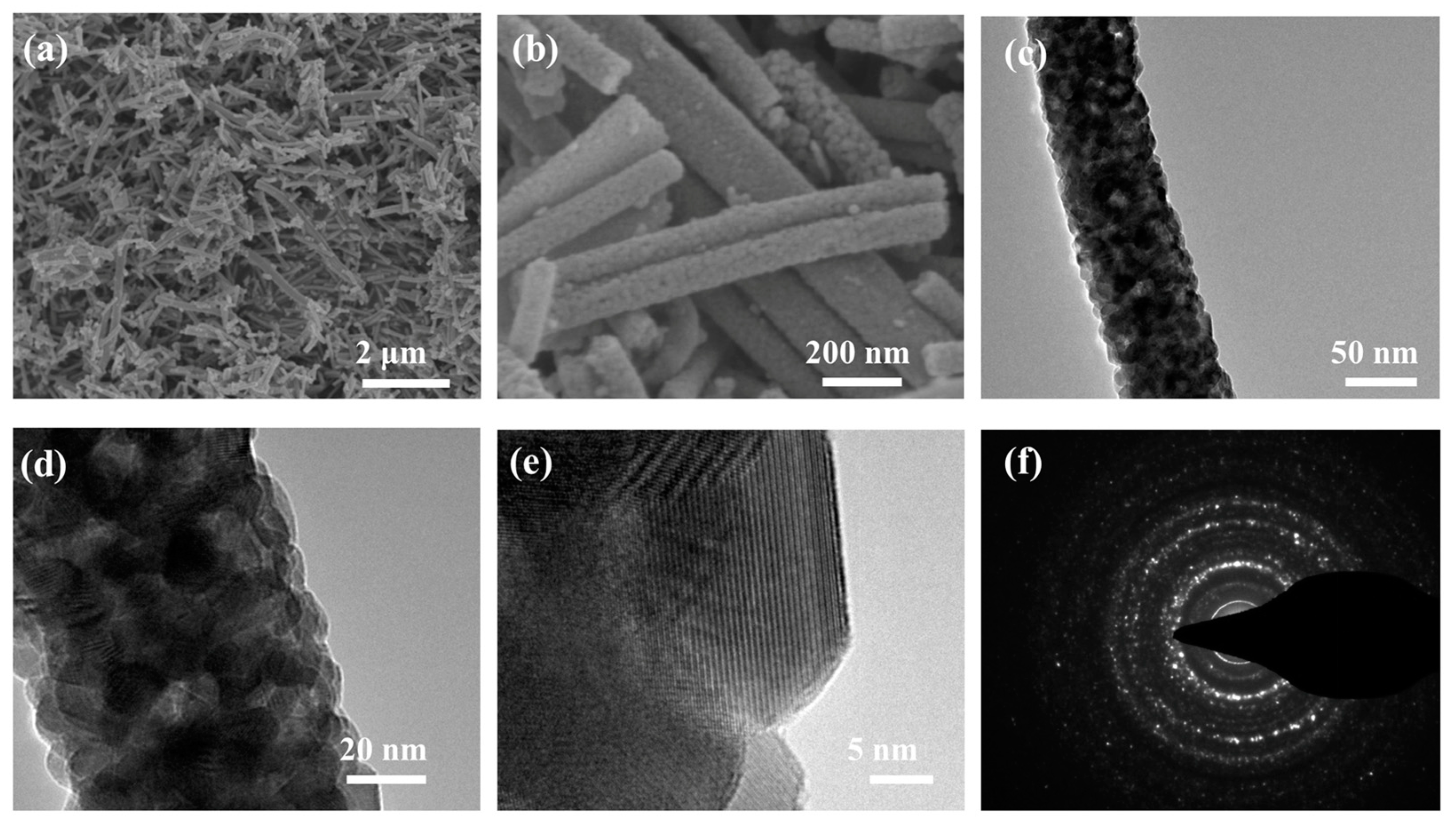
Figure 1. Morphological characterization of the In2O3 nanofibers sample. (a,b) SEM images, (ce) TEM images, (f) SAED patterns.
Inorganics 12 00336 g001
Figure 2. Morphological characterization of In2O3/C composite nanofibers sample. (ac) SEM images, (d,e) TEM images, SAED patterns in the insert of (e), (f) HRTEM image, (gk) the elemental maps.
Inorganics 12 00336 g002
Figure 3. (a) XRD patterns In2O3 nanofibers and In2O3/C composite nanofibers. (b) Full XPS spectrum of In2O3/C composite nanofibers, (cf) High-resolution In 3d, C 1s, N 1s, and O1s XPS spectrum of In2O3/C composite nanofibers.
Inorganics 12 00336 g003
Figure 4. Electrochemical characterization of two nanofiber-based half cells; (a) CV curves and (b) charge–discharge profiles of In2O3 nanofibers electrode in the initial 5 cycles, (c) CV curves and (e) charge–discharge profiles of In2O3/C composite nanofibers electrode in the initial 5 cycles, (d) cyclic performance and Coulombic efficiency curves of the two nanofiber-based electrodes, (f) rate performance for the two nanofiber-based electrodes, (g) capacity retention of these two electrodes at different current densities.
Inorganics 12 00336 g004
Figure 5. Morphological characterization of In2O3/C composite nanofibers sample after cycling. (a,b) SEM images and (c,d) TEM images. (ej) elemental maps.
Inorganics 12 00336 g005
Figure 6. Electrochemical impedance spectroscopy of the In2O3/C composite nanofiber and the In2O3 nanofiber electrodes after cycling.
Inorganics 12 00336 g006
Table 1. Electrochemical performance comparison table of present In2O3/C composite nanofibers with recent reported In2O3 and carbonaceous materials.
Electrode DescriptionCurrent Density
(mA g−1 )
Cycle NumberReversible Capacity
(mAh g−1 )
High Rate CapabilityReference
In2O3/C composite nanofibers300200571264 mAh g−1 at 3.2 A g−1This work
SnO2–In2O3/GNS6050969263 mAh g−1 at 0.6 A g−1[40]
C/In2O3 nanosheets100100893379 mAh g−1 at 2 A g−1[43]
In2O3/HPNC10002000623139 mAh g−1 at 20 A g−1[44]
In2O3/C fibers100500435190 mAh g−1 at 1.5 A g−1[41]
In2O3 NC-EBA200100910316 mAh g−1 at 20 A g−1[38]
In2O3/carbon100150720140 mAh g−1 at 1.0 A g−1[47]
Disclaimer/Publisher’s Note: The statements, opinions and data contained in all publications are solely those of the individual author(s) and contributor(s) and not of MDPI and/or the editor(s). MDPI and/or the editor(s) disclaim responsibility for any injury to people or property resulting from any ideas, methods, instructions or products referred to in the content.