Article

In Situ Synthesis of Ti:Fe2O3/Cu2O p-n Junction for Highly Efficient Photogenerated Carriers Separation

1
Engineering Research Center of Ministry of Education for Geological Carbon Storage and Low Carbon Utilization of Resources, Beijing Key Laboratory of Materials Utilization of Nonmetallic Minerals and Solid Wastes, National Laboratory of Mineral Materials, School of Material Sciences and Technology, China University of Geosciences, Beijing 100083, China
2
Collaborative Innovation Center of Atmospheric Environment and Equipment Technology, Jiangsu Key Laboratory of Atmospheric Environment Monitoring, Pollution Control School of Environmental Science and Engineering, Nanjing University of Information Science and Technology, Nanjing 210044, China
*
Author to whom correspondence should be addressed.
Inorganics 2023, 11(4), 155; https://doi.org/10.3390/inorganics11040155
Submission received: 26 February 2023 / Revised: 28 March 2023 / Accepted: 31 March 2023 / Published: 3 April 2023
(This article belongs to the Special Issue Photoelectrodes for Water Splitting)

Abstract

:
High photoelectrochemical water oxidation efficiency can be achieved through an efficient photogenerated holes transfer pathway. Constructing a photoanode semiconductor heterojunction with close interface contact is an effective tactic to improve the efficiency of photogenerated carrier separation. Here, we reported a novel photoanode p-n junction of Ti:Fe2O3/Cu2O (n-Ti:Fe2O3 and p-Cu2O), Cu2O being obtained by in situ reduction in CuAl-LDH (layered double hydroxides). The Ti:Fe2O3/Cu2O photoanode exhibits a high photocurrent density reaching 1.35 mA/cm2 at 1.23 V vs. RHE is about 1.67 and 50 times higher than the Ti:Fe2O3 and α-Fe2O3 photoanode, respectively. The enhanced PEC activity for the n-Ti:Fe2O3/p-Cu2O photoelectrode is due to the remarkable surface charge separation efficiency (ηsurface 85%) and bulk charge separation efficiency (ηbulk 72%) formed by the p-n junction and the tight interface contact formed by in situ reduction. Moreover, as a cocatalyst, CuAl-LDH can protect the Ti:Fe2O3/Cu2O photoanode and improve its stability to a certain extent. This study provides insight into the manufacturing potential of in situ reduction layered double hydroxides semiconductor for designing highly active photoanodes in the field of photoelectrochemical water oxidation.

1. Introduction

The energy crisis and environmental pollution caused by excessive fossil energy consumption are the major problems facing people in the 21st century. Photoelectrocatalysis hydrolysis technology exhibits considerable development prospects for solving energy problems. Currently, metal oxide semiconductors are mainly used in photoelectrocatalysis water decomposition [1]. The most common oxide semiconductor materials used as photoanodes are TiO2 [2,3,4,5], WO3 [6,7,8], BiVO4 [9,10,11], BiFeO3 [12,13], and Fe2O3 [14,15,16,17]. Suitable photoelectrocatalysis materials need an appropriate band gap, high stability, and environmental friendliness. Fe2O3 was first reported as the original mineral material for water oxidation photoanode materials in the 1980s [18]. Typically, α-Fe2O3 is an n-type semiconductor, which when presented with a hexagonal dense stack structure and suitable band gap (~2.0 eV), is non-toxic, low-cost, and thermodynamically stable, meaning it can be realized as a reversible hydrogen electrode (RHE) at 1.23 V. α-Fe2O3 is known as an ideal photocatalytic material, which with the maximum theoretical photocurrent of 12.6 mA/cm2 achieves a theoretical solar-to-hydrogen (STH) efficiency of ~16% [19]. However, pure α-Fe2O3 suffers from poor charge separation efficiency and slow water oxidation kinetics [18]. The severe electron–hole recombination of α-Fe2O3 causes a considerable loss of photogenerated carriers, making its photocatalytic efficiency much lower than its theoretical value.
In recent decades, various strategies have been explored to improve the efficiency of α-Fe2O3 photoanodes, ranging from designing different morphologies to improving the electron transport properties of the bulk and surface, changing the morphology of α-Fe2O3 so that its size is smaller than the hole diffusion length [20]. Doped α-Fe2O3 can also improve the electrical conductivity of elements, such as Ti [21], Co [22], F [23], P [24], etc. Incorporating another suitable semiconductor with α-Fe2O3 to construct heterojunction, such as TiO2 [25], ZnO [26], MnO2 [27], WO3 [28], C3N4 [29], Cu2O [30], etc., is a widely used strategy to improve performance [31]. Semiconductor promoter catalysts (FeOOH [32,33], CoP [34], LDH [35,36,37]) to combine with α-Fe2O3 have also been proposed [38]. Heterojunction construction is most commonly used to accelerate the diffusion of charge carriers under the internal electric field, resulting in more efficient separation and a longer charge carrier lifetime [39]. It is crucial to select suitable materials to compound with α-Fe2O3 to improve its photoelectrochemical water separation performance. Copper oxides exhibit great promise for solar energy conversion and heterogeneous photocatalysis due to their multi-electron transfer properties in narrow bandgap materials. Among them, cuprous oxide (Cu2O), as a low-cost visible-light-responsive material, is widely used for constructing the heterogeneous photocatalysis used for photoelectrochemical/photocatalytic reactions in solar energy conversion fields [40]. The Cu2O material matches the energy-band position of α-Fe2O3, and both absorb visible light. Combining α-Fe2O3 with Cu2O can effectively improve the photoelectrochemical properties of α-Fe2O3 [41,42,43]. Nano-sized cuprous oxide clusters can be obtained by reducing copper-containing hydrotalcite materials [40], and the cuprous oxide synthesized under alkaline conditions is a p-type semiconductor material.
Herein, we prepared Ti:Fe2O3/Cu2O composite photoanodes by an in situ partial reduction in Ti:Fe2O3/CuAl-LDH. The CuAl-LDH and Cu2O were prepared by in situ reduction, the tight interface between Ti:Fe2O3/CuAl-LDH and Cu2O/CuAl-LDH can reduce the interface charge loss of Ti:Fe2O3/Cu2O photoanodes. The Ti:Fe2O3/Cu2O photoanode has higher photoelectrochemical performance, exhibiting a more considerable photocurrent degree (1.35 mA/cm2) that is 1.69 times higher than the Ti:Fe2O3 photoanode (0.8 mA/cm2). Its surface charge separation efficiency (85%) and bulk phase charge transfer efficiency (64%) were 1.12 and 1.45 times higher than those of the Ti:Fe2O3 photoanode, respectively. The high photoelectrochemical performance may be attributed to forming a built-in electric field between p-Cu2O and n-Ti:Fe2O3, which promotes the high charge transfer on the interface. Through performing a photoanode stability test, we found that the existence of hydrotalcite can improve the photoanode’s photoelectrochemical water oxidation stability, which is due to the unreduced CuAl-LDH’s protective effect.

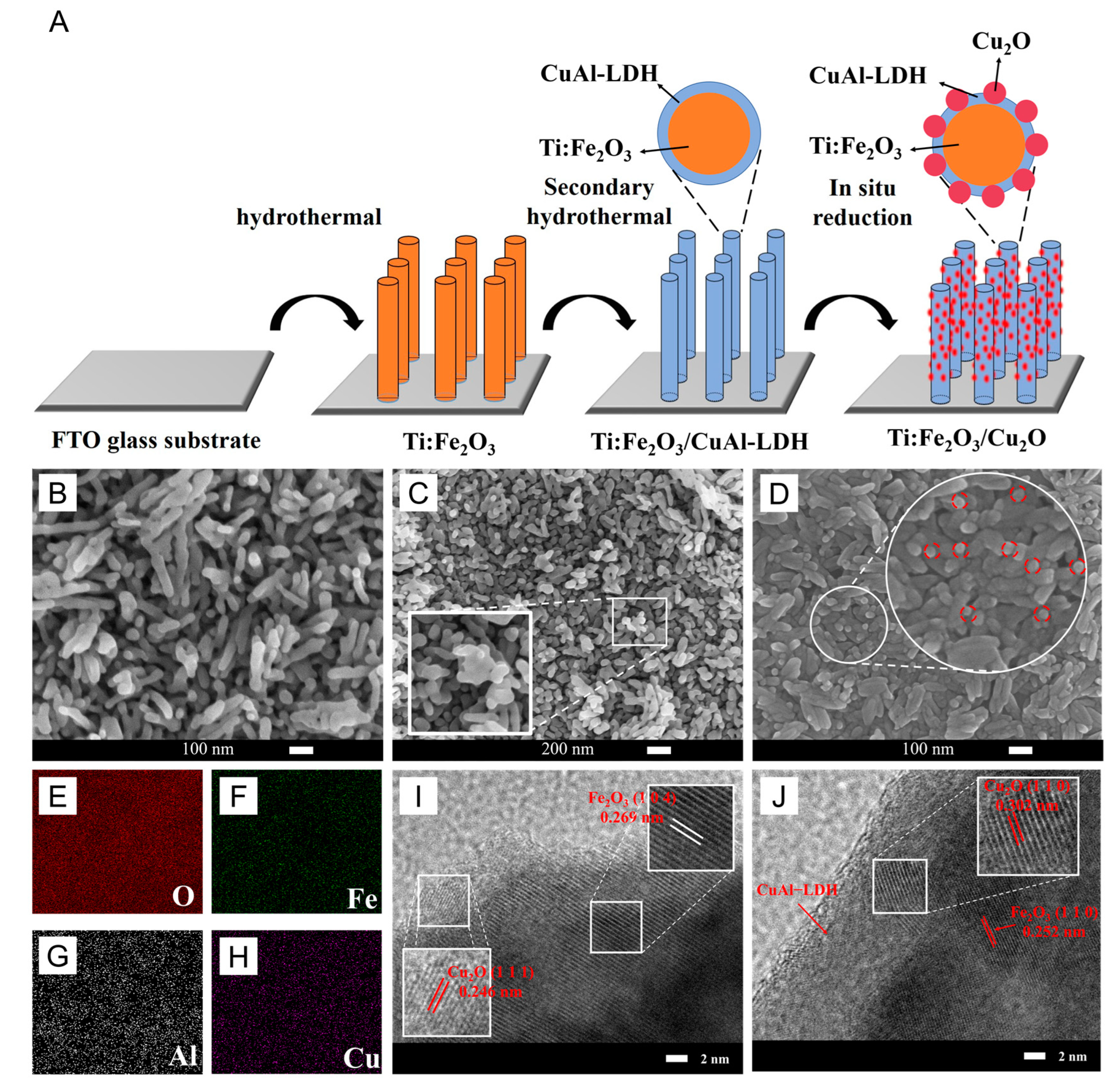
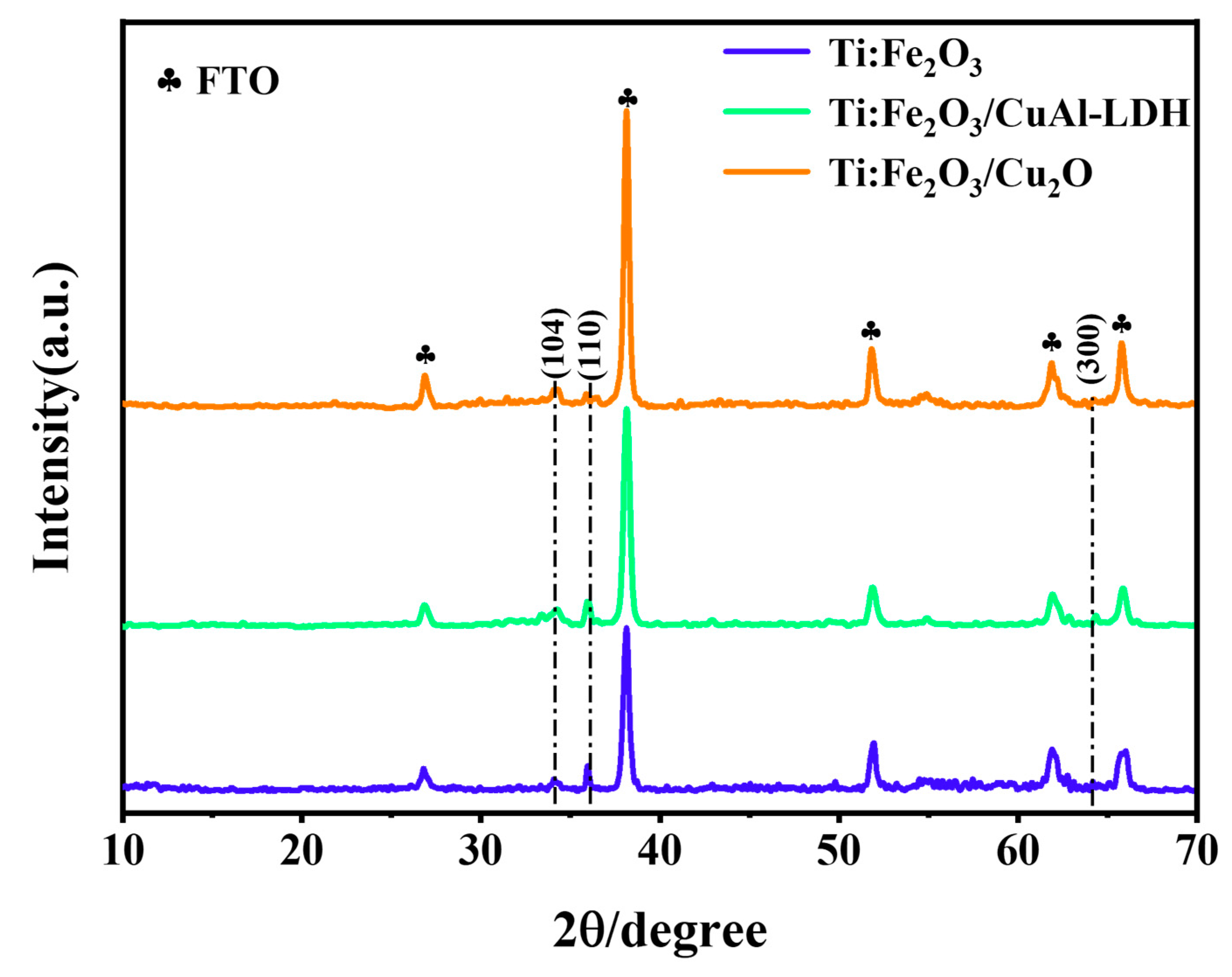
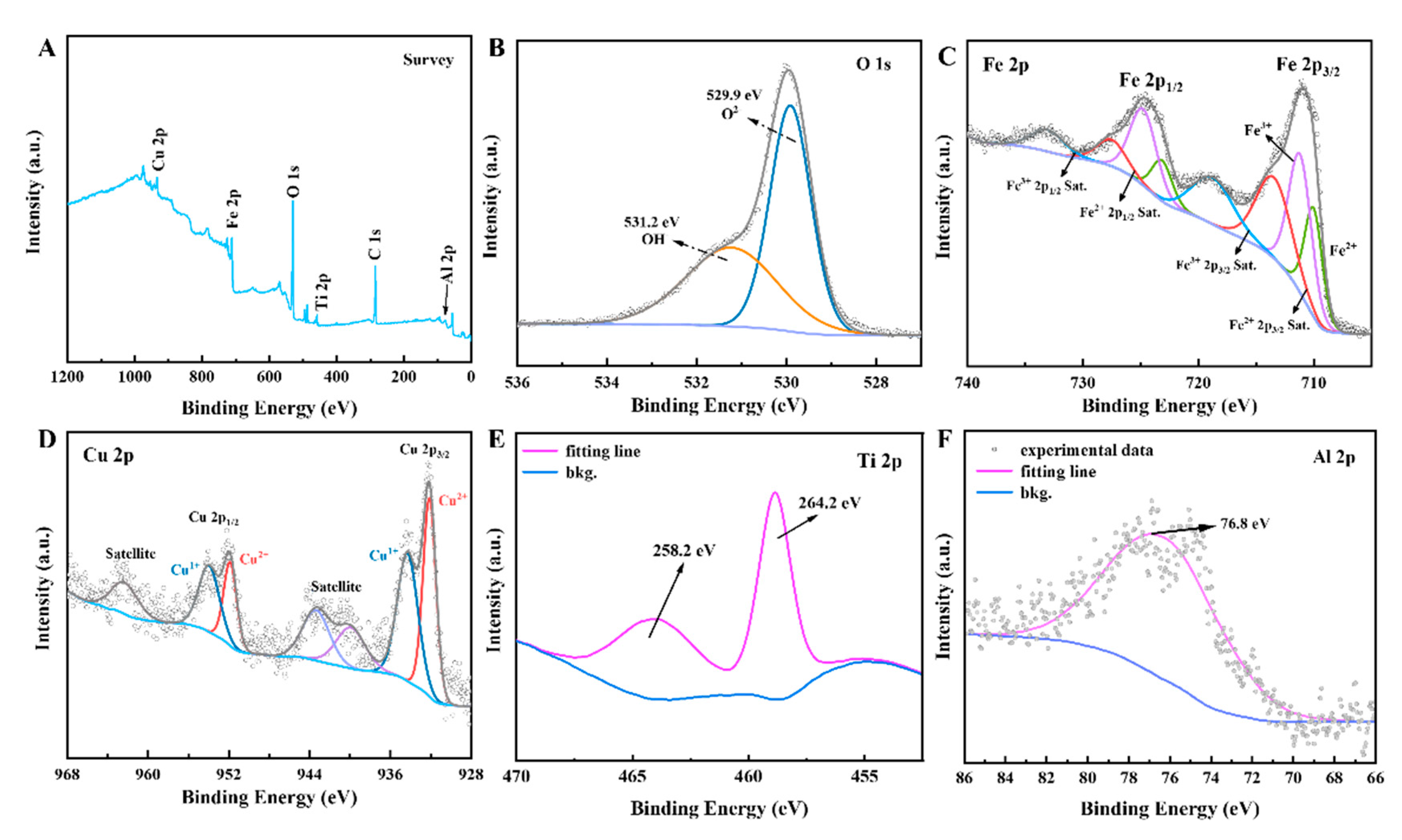
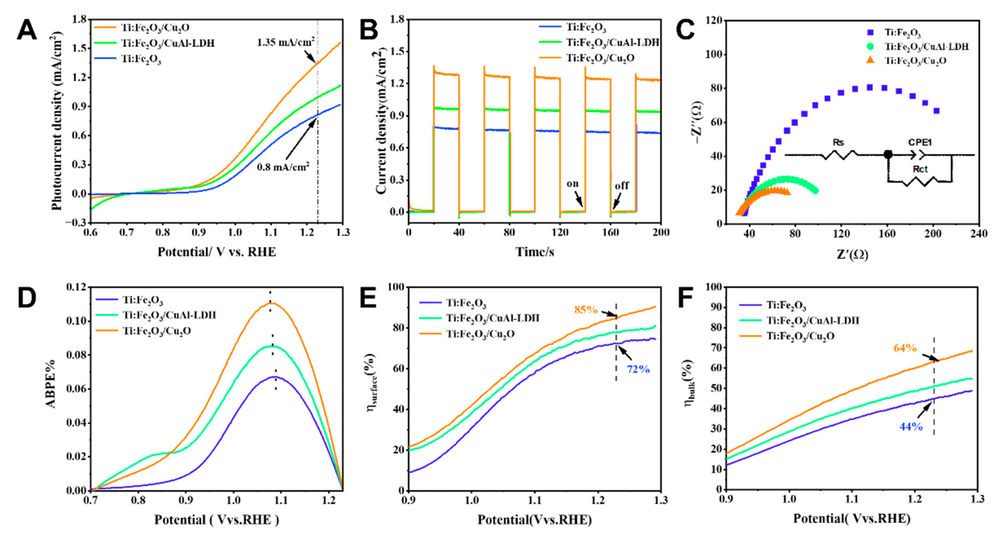
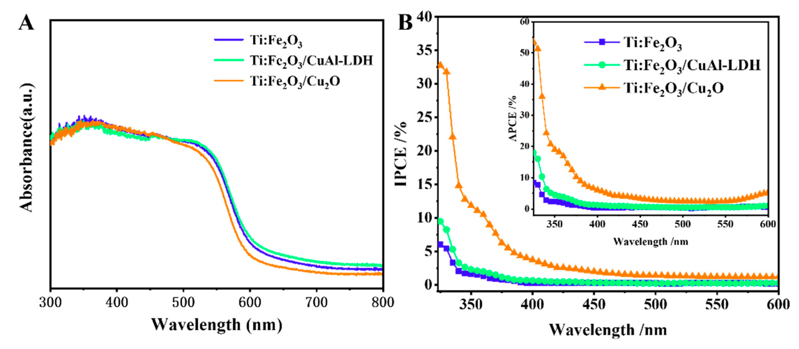
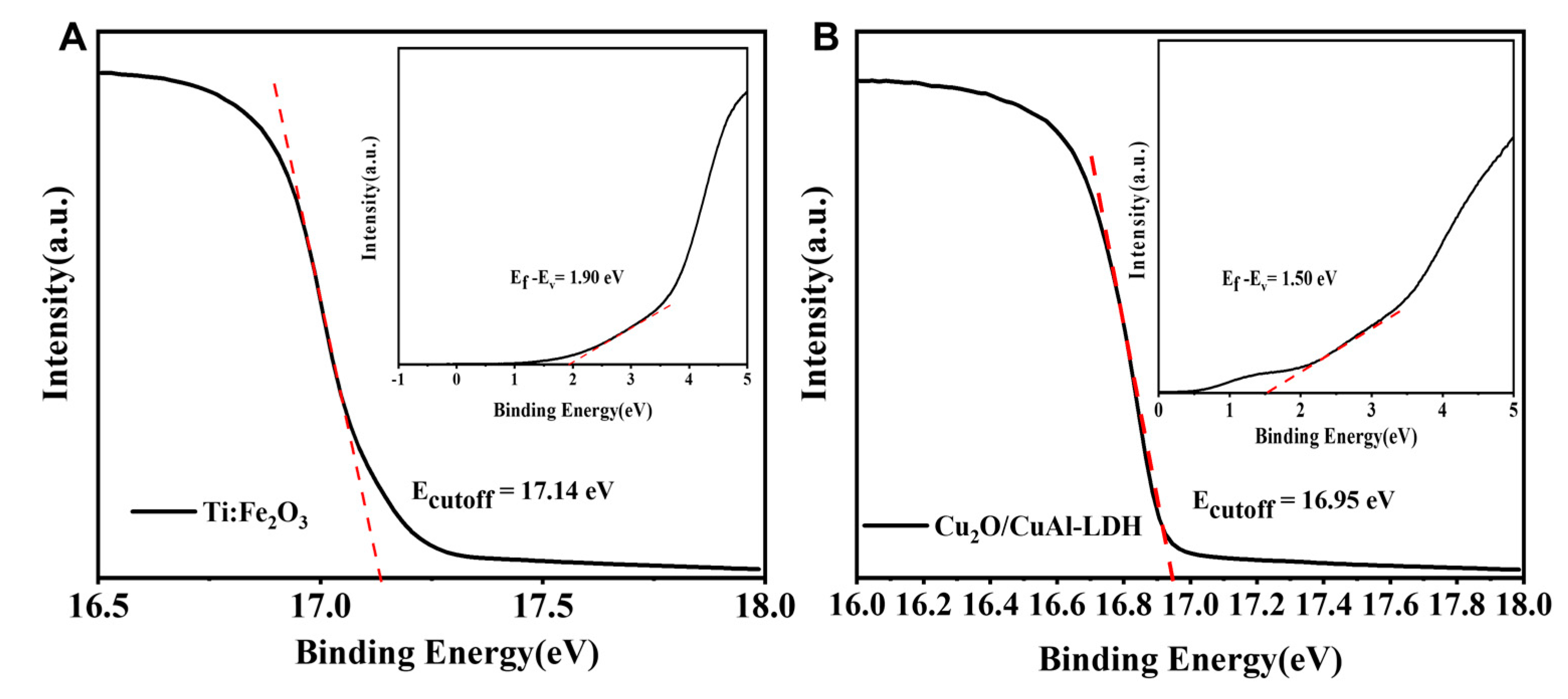
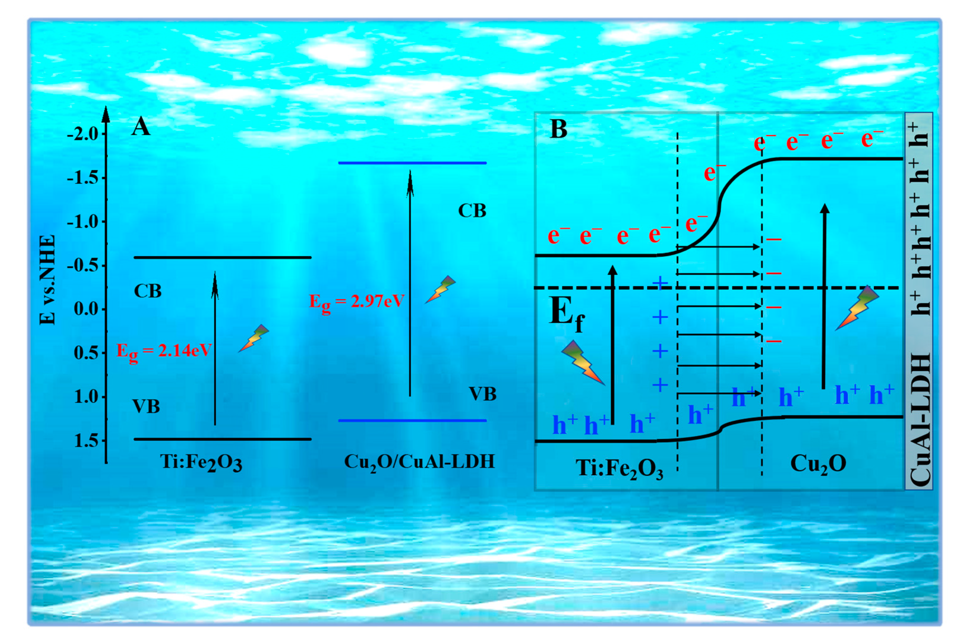
2. Results and Discussion

Figure 1A is an experimental flowchart of the Ti:Fe2O3/Cu2O composite photoanodes’ preparation process. First, Ti:Fe2O3 nanorods were grown on FTO glass by the hydrothermal method. Then, CuAl-LDH covered the Ti:Fe2O3 nanorods by a second-step hydrothermal method. The Ti:Fe2O3/Cu2O photoanode was finally obtained by in situ reduction with ascorbic acid. Figure 1B–D show the SEM images of the Ti:Fe2O3, Ti:Fe2O3/CuAl-LDH, and Ti:Fe2O3/Cu2O photoanodes. Ti:Fe2O3 exhibits a uniform fine nanorod structure (Figure 1B). After the hydrothermal growth of CuAl-LDH, a significant number of small nanosheets were grown on the surface of the Ti:Fe2O3 nanorods. After ascorbic acid reduction, the nanosheets and nanorods remained, and fine particles formed on the surface, as shown in Figure 1D. Figure 1E–H show the EDS mapping images of the Ti:Fe2O3/Cu2O electrode. Cu, Al, Fe, O, and other elements are uniformly distributed on the electrode surface. Due to the fact that the partial reduction in copper-containing hydrotalcite does not completely destroy the structure of hydrotalcite [40], the short reduction time resulted in small Cu2O particles. The two Cu and Al elements were evenly distributed, which is consistent with the results of the EDS spectrum. Figure 1I,J give the HRTEM images of the Ti:Fe2O3/Cu2O. The thickness of the hydrotalcite layer is about 10 nm. Cu2O nanoparticles with an average diameter of about 5 nm were uniformly distributed on the surface of the photoanode. The distinct lattice fringes with d-spacings of 0.246 nm and 0.302 nm correspond to the (1 1 1) and (1 1 0) planes of Cu2O nanoparticles, respectively, while the lattice fringes of 0.269 nm and 0.252 nm were ascribed to the (1 0 4) and (1 1 0) planes of Fe2O3, respectively. Through SEM and HRTEM tests, we proved that the CuAl LDH layer grew on the surface of Ti:Fe2O3, and after in situ reduction, Cu2O was uniformly distributed on the surface of the photoanode.
Figure 2 and Figure S1 show the XRD patterns of Ti:Fe2O3, Ti:Fe2O3/CuAl-LDH, and Ti:Fe2O3/Cu2O/CuAl-LDH composite photoanodes. The peaks at 33.2°, 35.6°, and 63.9° belong to the (1 0 4), (1 1 0), and (3 0 0) crystal planes of α-Fe2O3 (JCPDS 33-0664), respectively. Compared with pure α-Fe2O3, the peak of the (1 1 0) crystal plane in Ti:Fe2O3 hematite decreased and shifted to a high angle, which indicated that Ti-doped Fe2O3 affected the crystal structure of pure α-Fe2O3. Unfortunately, the α-Fe2O3 peaks were small, and no characteristic diffraction peaks belonged to CuAl-LDH or Cu2O. This may be due to the relatively thin thickness of the hematite layer compared with the SnO2 layer on the FTO substrate (marked by clubs in Figure 2), resulting in a relatively weak signal. Similarly, the CuAl-LDH and Cu2O particles were smaller and therefore not detected in the XRD spectrum.
Consequently, we examined the composition and chemical state of the CuAl-LDH and Cu2O particles by XPS spectroscopy. The full XPS spectrum of the Ti:Fe2O3/Cu2O composite photoanode (Figure 3A) shows that Fe, Ti, Cu, Al, O, and other elements exist in the composite photoanode. Figure 3B shows the O 1s XPS spectrum of the Ti:Fe2O3/Cu2O composite, where the lattice oxygen (O2−) occurs at a binding energy of 529.9 eV, while it is 531.2 eV in the hydroxyl group (OH) [44]. The existence of a large amount of hydroxyl oxygen further proves that CuAl-LDH is not completely reduced, and the partial amount of CuAl-LDH left on the surface of Ti:Fe2O3 may play a co-catalysis role, facilitating the charge transport. Figure 3C is exemplary of the XPS spectrum of Fe 2p. Fe 2p1/2 and Fe 2p3/2 appear at 724.6 eV and 710.9 eV, respectively, and two satellite peaks appear at the binding energies of 719.5 eV and 735.6 eV, which are characteristic peaks of Fe3+, proving the existence of Fe3+ in the sample [44]. The peaks belonging to Fe 2 p3/2 and Fe 2p1/2 appeared at binding energies of 710.0 eV and 723.2 eV, respectively, and two satellite peaks appeared at the binding energies of 713.7 eV and 727.7 eV, which are characteristic peaks of Fe2+ [45]. This indicates the presence of Fe2+ in the sample, which suggests that ascorbic acid reduces part of Fe3+ on the sample surface to Fe2+ while reducing CuAl-LDH. In Figure S2, after Ti:Fe2O3 was composited with CuAl-LDH, the XPS peaks of O 1s and Fe 2p are both shifted to low binding energy, which indicates that the electrons transfer from CuAl-LDH to Ti:Fe2O3. However, after CuAl-LDH undergoes partial reduction in situ, the binding energy of O 1s moves to the lower direction, while the binding energy of Fe3+ moves to the higher direction. The shifted binding energy is attributed to intimate interfacial and chemical interaction formed between Ti:Fe2O3 and Cu2O in the composite and the photoelectron migration occurs from Ti:Fe2O3 to Cu2O, which is consistent with the electronic trend of the p-n junction. Figure 3D shows the acceptable XPS spectrum of Cu 2p, and the binding energies of 932.0 eV and 951.8 eV are the peaks of Cu 2p3/2 and Cu 2p1/2, respectively, while the three satellites at the binding energies of 939.9 eV, 943.4 eV, and 962.5 eV peak represent the presence of Cu2+. The peaks of Cu 2p3/2 and Cu 2p1/2 at 934.2 eV and 954.0 eV, respectively, [40] represent the presence of Cu+. Figure S3 compared the XPS peaks of Cu and Al in Ti:Fe2O3/CuAl-LDH photoanode before and after in situ reduction. The results show no Cu1+ in Fe2O3/CuAl-LDH photoanode. After reduction, the XPS peak of Al shifted to the low binding energy direction. The result indicates that CuAl-LDH enriches electrons, which is more conducive to hole transfer to the surface of the photoanode. Figure 3E is the nuanced XPS spectrum of Ti 2p. The binding energies are 264.2 eV and 258.2 eV for Ti 2p1/2 and Ti 2p3/2, respectively, which indicates that only Ti4+ exists in the sample [46]. The characteristic peak of Al 2p3/2 appears at 76.8 eV in Figure 3F [44]. Additionally, the non-integrated peak belongs to the FTO base. In summary, Cu2O particles were successfully prepared on the Ti:Fe2O3 photoanode surface by in situ partial reduction in CuAl-LDH.
To evaluate the PEC performance of photoanodes, we performed photoelectrochemical tests on a series of photoanodes using a three-electrode system in a 1M KOH (pH = 13.8) electrolyte solution. Figure 4A is the LSV test of the photoanode. As the applied-bias voltage gradually increases, the photocurrent of all photoanodes also gradually increases, and the photoanodes have the highest photocurrent at 1.23 V vs. RHE Fe2O3/Cu2O. In Figure 4B and Table 1, the photocurrent of the Ti:Fe2O3/Cu2O photoanode at 1.23 V vs. RHE reached 1.35 mA/cm2, which was 1.47 times that of the Ti:Fe2O3/CuAl-LDH photoanode (0.92 mA/cm2) and 1.69 times that of the Ti:Fe2O3 photoanode (0.80 mA/cm2). In Figure S4, the photocurrent of pure Fe2O3 is 0.027 mA/cm2, which is 1/50th of Ti:Fe2O3/Cu2O, possibly due to the original photoanode’s higher surface kinetics. The surface kinetics are due to the reloading of CuAl-LDH with Cu2O and the formation of a p-n junction between Ti:Fe2O3 and Cu2O, which facilitates the transfer of charges. The transient photocurrents of the photoanodes are shown in Figure 4C. All photoanodes have high photoresponse characteristics, and Ti:Fe2O3/Cu2O photoanodes have the highest photocurrent density among all the samples, which is consistent with the LSV results. Then, we carried out electrochemical impedance (EIS) tests, as shown in Figure 4C. It is known that the radius of the high-frequency region in the impedance spectrum represents the electron transfer resistance, and the smaller the semicircle represents the higher the transfer resistance. The Ti:Fe2O3/Cu2O photoanode has the most negligible electrochemical impedance. As mentioned earlier, the electrochemical impedance test also verified the photocurrent. Figure 4D depicts the applied-bias photo-to-current conversion efficiency (ABPE) under the applied-bias voltage. The peaks of ABPE appear at different voltages, namely 0.107 V vs. 0.11% of RHE belongs to the Ti:Fe2O3/Cu2O photoanode, while 0.089% of 1.08 V vs. RHE and 0.07% of 1.09 V vs. RHE belong to the Ti:Fe2O3/CuAl-LDH and Ti:Fe2O3 photoanodes, respectively. This means that the CuAl-LDH/Cu2O layer obtained by in situ reductions is more active than CuAl-LDH in terms of activity. Figure 4E,F show the surface separation efficiency and bulk phase separation efficiency of the photoanode, respectively. The Ti:Fe2O3/Cu2O photoanode has the highest surface separation efficiency and bulk phase separation efficiency at 1.23 V vs. RHE, 85%, and 64%, respectively. The surface separation efficiency and bulk phase separation efficiency of the Ti:Fe2O3/CuAl-LDH photoanode were 77% and 51%, respectively. The surface separation efficiency and bulk phase separation efficiency of the Ti:Fe2O3 photoanode at 1.23 V vs. RHE were 72% and 44%, respectively. The enhanced separation efficiency is due to the Ti:Fe2O3/Cu2O photoanode junction formed and the closed interface contact between n-Ti:Fe2O3 and p-Cu2O. Furthermore, CuAl-LDH as a co-catalyst can reduce the loss of photogenerated carriers and improve separation efficiency. Recombination enables it to be smoothly conducted to the electrolyte solution without being trapped by the surface states. After reduction to Cu2O, the formation of the p-n junction can further promote the separation of carriers, thereby improving the separation efficiency. The Mott-Schottky curve (M-S) test was performed on the photoanode, as shown in Figure S5A. It is known that the slope of the Mott-Schottky curve is inversely proportional to the carrier concentration of the semiconductor. Figure S5A shows that the M-S curve of the Ti:Fe2O3/Cu2O photoanode has a minor slope; therefore, it has a high carrier concentration. These results are also consistent with the above test results. Additionally, according to the M-S curve of the Ti:Fe2O3/Cu2O sample, Ti:Fe2O3 and Cu2O form a p-n junction in the Ti:Fe2O3/Cu2O sample. The photoanode’s stability is vital for its application, so the long-term steady-state photocurrent density was investigated, as shown in Figure S5B. By comparing the strength of the Ti:Fe2O3/Cu2O photoanode with or without CuAl−LDH, we found that, with the presence of CuAl-LDH, the photoanode’s stability significantly improved, with no apparent attenuation during the test. On the contrary, in the absence of CuAl-LDH, the photoanode exhibited relatively high initial performance levels; however, the stability was severely degraded. As practical applications require high stability, the presence of CuAl-LDH can effectively improve the Ti:Fe2O3/Cu2O photoanode’s strength. Table S1 shows the comparison of photocurrent density between this sample and other researchers’ samples [30,44,47,48,49,50].
The light absorption properties are an essential part of studying the PEC performance. We evaluated the samples’ light absorption properties by analyzing the UV-vis spectrum, as shown in Figure 5A. The absorption edge cutoff wavelengths of Ti:Fe2O3 and Ti:Fe2O3/CuAl-LDH are about 610 nm, which is consistent with the bandgap of 2.07 eV in Ti:Fe2O3, proving visible light absorption. The absorption edge of Ti:Fe2O3/Cu2O has a slight blue shift, which may be related to the light absorption of the CuAl-LDH/Cu2O mixture. To verify the effect of light absorption on photocurrent, the monochromatic incident photon-to-electron conversion efficiency (IPCE) was measured to evaluate the contribution of incident light absorption to the photocurrent (Figure 5B). Compared with Ti:Fe2O3, Ti:Fe2O3/Cu2O had a significantly enhanced IPCE value in the wavelength range from 323 nm to 600 nm. The highest IPCE value of Ti:Fe2O3/Cu2O at 323 nm is 32.7%, while Ti:Fe2O3 is 6.0%, which may benefit from the combined contribution of CuAl-LDH and Cu2O to the PEC performance. In addition, the photoanode’s PEC performance was further evaluated by the absorption photon-current efficiency. The maximum APCE of Ti:Fe2O3/Cu2O was 54.8% at 400 nm, which increased to 7.0% at 600 nm (Figure 5B, inset), which means that this photoanode’s PEC water splitting was in a wide wavelength range from 400 to 600 nm.
To explore the mechanism of Ti:Fe2O3/Cu2O more intuitively, its energy-band structure was calculated by UPS spectroscopy (Figure 6) and UV-vis spectroscopy. The conduction-band (CB) and valence-band (VB) energies were calculated by UPS spectroscopy. The forbidden bandwidth was obtained by UV-vis spectroscopy. In Figure S6, the bandgaps of Ti:Fe2O3 and Cu2O (with CuAl-LDH) are 2.07 eV and 2.24 eV, respectively. The calculation results are shown in Table 2. As expected, the valence-band positions (vs. RHE) of Ti:Fe2O3 and Cu2O were 1.48 eV and 1.27 eV, respectively, while the conduction-band positions were −0.59 eV and −1.67 eV, respectively.
Figure 7A shows the energy bands. The relative positions of the structures and the possible mechanism are given in Figure 7B. The electrons at the interface are transferred from n-type Ti:Fe2O3 to p-type Cu2O so that a built-in electric field directed from Ti:Fe2O3 to Cu2O is formed at the interface, promoting the carrier transfer between the interfaces. When applying bias voltage and light to the Ti:Fe2O3/Cu2O photoanode, the photogenerated holes (h+) will transfer to the surface of the photoanode through the built-in electric field and proceed to an oxidation reaction with water on the surface of the Ti:Fe2O3/Cu2O. Meanwhile, photogenerated electrons (e) are transmitted to the opposite electrode along the external circuit to participate in the reduction reaction. As illustrated in Figure S7, all the photovoltaic signals are positive, suggesting that photogenerated holes have migrated to the surface of the electrodes, which is consistent with the above conclusions. At the same time, the unreduced CuAl-LDH exists on the surface of the Ti:Fe2O3/Cu2O composite photoanode as a cocatalyst, which promotes the transfer of photogenerated holes to the electrode surface to participate in the oxidation reaction, which also protects the photoanode to a certain extent. The presence of CuAl-LDH enhances the stability of the α-Fe2O3/Cu2O composite photoanode.

3. Experimental Section

3.1. Materials

We purchased potassium hydroxide (KOH, >90%) and sodium nitrate (NaNO3, >99%) from Xilong Science Co., Ltd. (Shantou, China), and purchased titanium tetrachloride (TiCl4, >99.5%) from Aladdin Reagent Co., Ltd. (Shanghai, China) We purchased anhydrous sodium sulfite (Na2SO3, >97%), ammonium fluoride (NH4F, >98%), and ferric chloride (FeCl3·6H2O, >99%) from McLean Biochemical Technology Co., Ltd. (Shanghai, China). We purchased copper nitrate (Cu(NO3)2·3H2O) and aluminum nitrate (Al (NO3)·9H2O) from Sinopharm. We purchased urea from Jingxi Chemical Technology Co., Ltd. (Shenzhen, China). We purchased fluorine-doped tin oxide (FTO; F:SnO2, <15 ohm SQ−1) glass from the NipponSheet Glass CompanyLimited (Tokyo, Japan). We ultrasonically cleaned it in acetone, ethanol, and water for 30 min and then dried it before the experiment. We used ultrapure water (18.2 m Ω·cm) provided by reverse osmosis, ion exchange, and filtration in the whole experimental process. All materials were used directly without any purification.

3.2. Preparation of Ti:Fe2O3 Photoanode

We fabricated the Ti:Fe2O3 photoanode by the hydrothermal method. First, we mixed 0.15M ferric chloride (FeCl3·6H2O) and 1.0M sodium nitrate (NaNO3) in 20 mL of the aqueous solution, stirred at room temperature for 30 min until the mixing was complete, and then added a certain amount of 1M TiCl4 ethanol solution to the mixed solution (Ti:Fe atomic ratio is 1:100). We poured a thoroughly mixed solution into a polytetrafluoroethylene-lined high-pressure reaction kettle and leaned a piece of cleaned fluorine-doped tin oxide (FTO) glass against its inner wall. Subsequently, we kept the autoclave in an oven at 100 °C for 12 h to obtain FeOOH films. We rinsed the resulting FeOOH films with deionized water and dried them with a nitrogen stream. Finally, we used a heating rate of 5 °C min−1 to obtain the target Ti:Fe2O3 photoanode by annealing at 550 °C for two hours and 700 °C for 20 min in air.

3.3. Preparation of Ti:Fe2O3/CuAl-LDH Photoanode

We prepared the Ti:Fe2O3/CuAl-LDH photoanode by the hydrothermal method. We designed a mixed solution containing 0.003M Cu(NO3)2·3H2O and 0.001M Al(NO3)3·9H2O. We added the hybrid solution to a polytetrafluoroethylene-lined autoclave, hydrothermally reacted it at 100 °C for 60 min, cooled to room temperature, rinsed, and then dried for later use. At the same time, we prepared the comparative samples without adding Al(NO3)3·9H2O, and other conditions remained unchanged.

3.4. Preparation of Ti:Fe2O3/Cu2O Photoanode

We used the in situ reduction method to prepare the Ti:Fe2O3/Cu2O photoanode, which comprised 0.5M ascorbic acid solution adjusted to pH = 10 with 1M NaOH solution. We soaked the series of photoanodes in the ascorbic acid solution for 45 min, removed them, rinsed with deionized water, and dried at room temperature.

3.5. Characterization

A JEOL JSM-7800 F scanning electron microscope (SEM) coupled with an energy-dispersive spectrum (EDS; Aztec from Oxford) and JEOL JEM-2100 transmission electron microscopy (TEM and HRTEM) was used to determine the surface morphology. The phase composition was confirmed by the X-ray diffraction (XRD) patterns (2θ ranging from 10° to 80°). Additionally, the chemical composition was measured via X-ray photoelectron spectroscopy (XPS; Thermo ESCALAB 250XI, Al-Kα X-ray) analyses. Regarding the optical property of the samples, the UV-vis spectra were recorded by a DU-8B UV-vis double-beam spectrophotometer. Furthermore, ultraviolet photoelectron spectroscopy (UPS) measured by ESCALAB 250Xi using non−monochromatized He-Iα radiation (UPS, hʋ = 21.22 eV) was performed to determine the electronic band position. The calculation process of the valence-band maximum (EVBM) and conduction-band minimum (ECBM) is as follows [51]:
W o r k f u n c t i o n = 21.22   e V E c u t o f f
W o r k f u n c t i o n = 0 E f
E V = W o r k f u n c t i o n + E o n s e t
E C = E V E g
where Ecutoff, Eonset, and Eg are the high-binding-energy cutoff, low-binding-energy onset, and bandgap, respectively.
All the semiconducting properties of the samples were determined by using a three-electrode cell in a 1.0M KOH (pH = 13.8) electrolyte undergoing a front illumination (from semiconducting direction) from a 300 W Xenon lamp equipped with an AM 1.5 G filter (100 mW cm−2). Electrochemical impedance spectroscopy (EIS) was operated at an AC voltage of 5 mV with frequencies ranging from 100 kHz to 0.01 Hz under visible light illumination. The final results for the Ag/AgCl electrode were converted to the reversible hydrogen electrode (RHE) according to [46]:
E RHE = E Ag/AgCl + E Ag/AgCl vs. NHE 0 + 0.0591   V × pH
( E Ag/AgCl vs. NHE 0 = 0.1976   V   vs.   NHE   at   25   ° C )
where ERHE is the potential versus vs. RHE, EAg/AgCl is the experimental potential measured vs. the Ag/AgCl reference electrode, and E0Ag/AgCl is the standard potential of the Ag/AgCl vs. NHE (0.1976 V at 25 °C). The linear-sweep voltammogram (LSV) curves were plotted at a scan rate of 10 mV s−1 by sweeping the potential in the positive direction. For stability measurements, the long-term amperometric photocurrent density-time curve was conducted under continuous irradiation with a bias of 1.23 V vs. RHE.
The applied-bias photon-to-current efficiency (ABPE) of the solar-driven water splitting process was used to quantify the photoanode’s performance, which can be calculated based on the measured photocurrent density using the following [46]:
ABPE ( % ) = ( 1 . 23 V ) × J P × 100
where J is the photocurrent density (mA cm−2) reads from the LSV curve, V is the applied bias (VRHE), and P is the incident light density (100 mW cm−2).
The incident photon-to-current efficiency (IPCE) was measured under monochromatic irradiation from a 300 W xenon arc lamp coupled with a monochromator (Zolix, Omni−λ 300) at 1.23 V vs. RHE following [46]:
IPCE % = 1240 J p h ( λ ) P ( λ ) λ × 100
where Jph(λ), λ, and P(λ) are photocurrent density (mA cm−2), wavelength of light (nm), and power density of monochromatic light (mW cm−2), respectively, which were measured by a calibrated Si detector.
Absorbed photon-to-current efficiency (APCE) was determined at each wavelength by dividing the IPCE by the light harvesting efficiency (LHE) according to the following [46]:
LHE = 1 10 A ( λ )
APCE ( % ) = IPCE ( % ) LHE
where A(λ) is the absorbance at wavelength.
The Nyquist diagram of electrochemical impedance spectroscopy (EIS) was collected by applying an AC voltage amplitude of 5 mV in the frequency range from 105 to 10−1 Hz without external bias and light (100 MW cm−2).

4. Conclusions

In summary, we successfully fabricated a Ti:Fe2O3/Cu2O photoanode by conducting an in situ reduction in Ti:Fe2O3/CuAl-LDH by ascorbic acid, which improved the PEC performance of hematite materials. The tight p–n junction structure formed by in situ reduction can boost efficient separation and transfer of the carriers to a certain extent and reduce the charge loss at the interface. Moreover, CuAl-LDH also acted as a cocatalyst to provide a photogenerated hole transport pathway and a protective layer, enhancing the photogenerated carrier transport efficiency and the photoanode’s stability. At 1.23 V vs. RHE, the photocurrent of the photoanode reached 1.35 mA/cm2, which is 1.69 times that of Ti:Fe2O3, and the surface charge separation efficiency reached 85%. The excellent PEC performance can be attributed to the construction of the p-n junction between n-Ti:Fe2O3 and p-Cu2O, as well as the synergistic effect of the CuAl-LDH cocatalyst. The synergistic effect of the p-n junction and the CuAl-LDH cocatalyst can effectively accelerate charge transport and inhibit recombination by improving the charge separation and transferring efficiency. This work reveals that the PEC performance and stability of the composite photoanode can be simultaneously improved by in situ reductions in the cocatalyst, which is partially reduced to a low-valence metal oxide, thereby providing a new strategy for the design of photoanodes for photoelectrochemical water oxidation.

Supplementary Materials

The following supporting information can be downloaded at: https://www.mdpi.com/article/10.3390/inorganics11040155/s1, Figure S1: (A) XRD spectra of pure Fe2O3 and Ti:Fe2O3. (B) The enlarged XRD spectra of the (110) peaks of Fe2O3 and Ti:Fe2O3; Figure S2: XPS spectra of Ti:Fe2O3, Ti:Fe2O3/CuAl-LDH and Ti:Fe2O3/Cu2O: (A) O 1s, (B) Fe 2p; Figure S3: XPS spectra of Ti:Fe2O3/CuAl-LDH and Ti:Fe2O3/Cu2O: (A) Cu 2p, and (B) Al 2p; Figure S4: Photocurrent density vs. time (I-T) curve; Figure S5: (A) M-S plots of Ti:Fe2O3, Ti:Fe2O3/CuAl-LDH, and Ti:Fe2O3/Cu2O photoanode. (B) Photoanode stability test; Figure S6: (A) Plots of the (αhν)1/2 vs. photon energy (hν) for Ti:Fe2O3. (B) UV-vis DRS (inset: plots of the (αhν)2 vs. photon energy (hν) for CuAl-LDH/Cu2O) of CuAl-LDH/Cu2O; Figure S7: Surface photovoltage (SPV) plots, the insert in (a) is the SPV measurement configuration; Table S1: Comparison of Photocurrent density with other Fe2O3 materials. (References [30,44,47,48,49,50] are cited in the Supplementary Materials).

Author Contributions

All authors contributed to the concept and design of this study. T.S. carried out material preparation, data collection, and analysis. T.S. wrote the first draft of the manuscript, and all authors commented on the previous versions of the manuscript. T.S. had full access to all data used in this study and T.S. take complete responsibility for the integrity of the data and the accuracy of the data analysis. All authors have read and agreed to the published version of the manuscript.

Funding

This work was partly supported by the National Natural Science Foundation of China (Grant No. 21978276) and the Fundamental Research Funds for the Central Universities (Grant No. 2652019157, 2652019158, 2652019159).

Data Availability Statement

All authors had full access to all of the data in this study and I take complete responsibility for the integrity of the data and the accuracy of the data analysis.

Conflicts of Interest

The authors declare no conflict of interest.

References

  1. Yao, T.; An, X.; Han, H.; Chen, J.Q.; Li, C. Photoelectrocatalytic Materials for Solar Water Splitting. Adv. Energy Mater. 2018, 8, 1800210. [Google Scholar] [CrossRef]
  2. Gong, J.; Pu, W.; Yang, C.; Zhang, J. Tungsten and nitrogen co-doped TiO2 electrode sensitized with Fe–chlorophyllin for visible light photoelectrocatalysis. Chem. Eng. J. 2012, 209, 94–101. [Google Scholar] [CrossRef]
  3. Wang, X.; Zhao, H.; Quan, X.; Zhao, Y.; Chen, S. Visible light photoelectrocatalysis with salicylic acid-modified TiO2 nanotube array electrode for p-nitrophenol degradation. J. Hazard. Mater. 2009, 166, 547–552. [Google Scholar] [CrossRef]
  4. Li, G.; Lian, Z.; Wang, W.; Zhang, D.; Li, H. Nanotube-confinement induced size-controllable g-C3N4 quantum dots modified single-crystalline TiO2 nanotube arrays for stable synergetic photoelectrocatalysis. Nano Energy 2016, 19, 446–454. [Google Scholar] [CrossRef]
  5. Liu, Z.; Wang, L.; Yu, X.; Zhang, J.; Yang, R.; Zhang, X.; Ji, Y.; Wu, M.; Deng, L.; Li, L.; et al. Piezoelectric-Effect-Enhanced Full-Spectrum Photoelectrocatalysis in p–n Heterojunction. Adv. Funct. Mater. 2019, 29, 1807279. [Google Scholar] [CrossRef]
  6. Fernández-Domene, R.M.; Sánchez-Tovar, R.; Lucas-granados, B.; Muñoz-Portero, M.J.; García-Antón, J. Elimination of pesticide atrazine by photoelectrocatalysis using a photoanode based on WO3 nanosheets. Chem. Eng. J. 2018, 350, 1114–1124. [Google Scholar] [CrossRef]
  7. Liu, Y.; Liang, L.; Xiao, C.; Hua, X.; Li, Z.; Pan, B.; Xie, Y. Promoting Photogenerated Holes Utilization in Pore-Rich WO3 Ultrathin Nanosheets for Efficient Oxygen-Evolving Photoanode. Adv. Energy Mater. 2016, 6, 1600437. [Google Scholar] [CrossRef]
  8. Liu, X.; Zhou, H.; Pei, S.; Xie, S.; You, S. Oxygen-deficient WO3−x nanoplate array film photoanode for efficient photoelectrocatalytic water decontamination. Chem. Eng. J. 2020, 381, 122740. [Google Scholar] [CrossRef]
  9. Yue, P.; She, H.; Zhang, L.; Niu, B.; Lian, R.; Huang, J.; Wang, L.; Wang, Q. Super-hydrophilic CoAl-LDH on BiVO4 for enhanced photoelectrochemical water oxidation activity. Appl. Catal. B Environ. 2021, 286, 119875. [Google Scholar] [CrossRef]
  10. Zhang, B.; Zhang, H.; Wang, Z.; Zhang, X.; Qin, X.; Dai, Y.; Liu, Y.; Wang, P.; Li, Y.; Huang, B. Doping strategy to promote the charge separation in BiVO4 photoanodes. Appl. Catal. B Environ. 2017, 211, 258–265. [Google Scholar] [CrossRef]
  11. Yu, F.; Li, F.; Yao, T.; Du, J.; Liang, Y.; Wang, Y.; Han, H.; Sun, L. Fabrication and Kinetic Study of a Ferrihydrite-Modified BiVO4 Photoanode. ACS Catal. 2017, 7, 1868–1874. [Google Scholar] [CrossRef]
  12. Arazas, A.P.R.; Wu, C.-C.; Chang, K.-S. Hydrothermal fabrication and analysis of piezotronic-related properties of BiFeO3 nanorods. Ceram. Int. 2018, 44, 14158–14162. [Google Scholar] [CrossRef]
  13. Huang, J.; Wang, Y.; Liu, X.; Li, Y.; Hu, X.; He, B.; Shu, Z.; Li, Z.; Zhao, Y. Synergistically enhanced charge separation in BiFeO3/Sn:TiO2 nanorod photoanode via bulk and surface dual modifications. Nano Energy 2019, 59, 33–40. [Google Scholar] [CrossRef]
  14. Wang, L.; Yang, Y.; Zhang, Y.; Rui, Q.; Zhang, B.; Shen, Z.; Bi, Y. One-dimensional hematite photoanodes with spatially separated Pt and FeOOH nanolayers for efficient solar water splitting. J. Mater. Chem. A 2017, 5, 17056–17063. [Google Scholar] [CrossRef]
  15. Grave, D.A.; Yatom, N.; Ellis, D.S.; Toroker, M.C.; Rothschild, A. The “Rust” Challenge: On the Correlations between Electronic Structure, Excited State Dynamics, and Photoelectrochemical Performance of Hematite Photoanodes for Solar Water Splitting. Adv. Mater. 2018, 30, 1706577. [Google Scholar] [CrossRef] [PubMed]
  16. Mesa, C.A.; Kafizas, A.; Francàs, L.; Pendlebury, S.R.; Pastor, E.; Ma, Y.; Le Formal, F.; Mayer, M.T.; Grätzel, M.; Durrant, J.R. Kinetics of Photoelectrochemical Oxidation of Methanol on Hematite Photoanodes. J. Am. Chem. Soc. 2017, 139, 11537–11543. [Google Scholar] [CrossRef] [Green Version]
  17. Noh, J.; Li, H.; Osman, O.I.; Aziz, S.G.; Winget, P.; Brédas, J.-L. Impact of Hydroxylation and Hydration on the Reactivity of α-Fe2O3 (0001) and (102) Surfaces under Environmental and Electrochemical Conditions. Adv. Energy Mater. 2018, 8, 1800545. [Google Scholar] [CrossRef]
  18. Li, J.; Chen, H.; Triana, C.A.; Patzke, G.R. Hematite Photoanodes for Water Oxidation: Electronic Transitions, Carrier Dynamics, and Surface Energetics. Angew. Chem. Int. Ed. 2021, 60, 18380–18396. [Google Scholar] [CrossRef]
  19. Li, J.; Cai, L.; Shang, J.; Yu, Y.; Zhang, L. Giant Enhancement of Internal Electric Field Boosting Bulk Charge Separation for Photocatalysis. Adv. Mater. 2016, 28, 4059–4064. [Google Scholar] [CrossRef]
  20. Dotan, H.; Kfir, O.; Sharlin, E.; Blank, O.; Gross, M.; Dumchin, I.; Ankonina, G.; Rothschild, A. Resonant light trapping in ultrathin films for water splitting. Nat. Mater. 2013, 12, 158–164. [Google Scholar] [CrossRef] [Green Version]
  21. Cao, D.; Luo, W.; Feng, J.; Zhao, X.; Li, Z.; Zou, Z. Cathodic shift of onset potential for water oxidation on a Ti4+ doped Fe2O3 photoanode by suppressing the back reaction. Energy Environ. Sci. 2014, 7, 752–759. [Google Scholar] [CrossRef]
  22. Szyja, B.M.; Podsiadły-Paszkowska, A. Helping Thy Neighbor: How Cobalt Doping Alters the Electrocatalytic Properties of Hematite. J. Phys. Chem. Lett. 2020, 11, 4402–4407. [Google Scholar] [CrossRef] [PubMed]
  23. Wang, C.; Long, X.; Wei, S.; Wang, T.; Li, F.; Gao, L.; Hu, Y.; Li, S.; Jin, J. Conformally Coupling CoAl-Layered Double Hydroxides on Fluorine-Doped Hematite: Surface and Bulk Co-Modification for Enhanced Photoelectrochemical Water Oxidation. ACS Appl. Mater. Interfaces 2019, 11, 29799–29806. [Google Scholar] [CrossRef] [PubMed]
  24. Rui, Q.; Wang, L.; Zhang, Y.; Feng, C.; Zhang, B.; Fu, S.; Guo, H.; Hu, H.; Bi, Y. Synergistic effects of P-doping and a MnO2 cocatalyst on Fe2O3 nanorod photoanodes for efficient solar water splitting. J. Mater. Chem. A 2018, 6, 7021–7026. [Google Scholar] [CrossRef]
  25. Zhang, P.; Yu, L.; Lou, X.W. Construction of Heterostructured Fe2O3-TiO2 Microdumbbells for Photoelectrochemical Water Oxidation. Angew. Chem. Int. Ed. 2018, 57, 15076–15080. [Google Scholar] [CrossRef]
  26. Noruozi, A.; Nezamzadeh-Ejhieh, A. Preparation, characterization, and investigation of the catalytic property of α-Fe2O3-ZnO nanoparticles in the photodegradation and mineralization of methylene blue. Chem. Phys. Lett. 2020, 752, 137587. [Google Scholar] [CrossRef]
  27. Wang, N.; Wu, L.; Li, J.; Mo, J.; Peng, Q.; Li, X. Construction of hierarchical Fe2O3@MnO2 core/shell nanocube supported C3N4 for dual Z-scheme photocatalytic water splitting. Sol. Energy Mater. Sol. Cells 2020, 215, 110624. [Google Scholar] [CrossRef]
  28. Bi, D.; Xu, Y. Synergism between Fe2O3 and WO3 particles: Photocatalytic activity enhancement and reaction mechanism. J. Mol. Catal. A Chem. 2013, 367, 103–107. [Google Scholar] [CrossRef]
  29. Xu, Q.; Zhu, B.; Jiang, C.; Cheng, B.; Yu, J. Constructing 2D/2D Fe2O3/g-C3N4 Direct Z-Scheme Photocatalysts with Enhanced H2 Generation Performance. Sol. RRL 2018, 2, 1800006. [Google Scholar] [CrossRef]
  30. Sharma, D.; Upadhyay, S.; Verma, A.; Satsangi, V.R.; Shrivastav, R.; Dass, S. Nanostructured Ti-Fe2O3/Cu2O heterojunction photoelectrode for efficient hydrogen production. Thin Solid Film. 2015, 574, 125–131. [Google Scholar] [CrossRef]
  31. Shen, S.; Lindley, S.A.; Chen, X.; Zhang, J.Z. Hematite heterostructures for photoelectrochemical water splitting: Rational materials design and charge carrier dynamics. Energy Environ. Sci. 2016, 9, 2744–2775. [Google Scholar] [CrossRef]
  32. Wang, L.; Nguyen, N.T.; Zhang, Y.; Bi, Y.; Schmuki, P. Enhanced Solar Water Splitting by Swift Charge Separation in Au/FeOOH Sandwiched Single-Crystalline Fe2O3 Nanoflake Photoelectrodes. ChemSusChem 2017, 10, 2720–2727. [Google Scholar] [CrossRef]
  33. Song, L.; Zhang, S. Formation of α-Fe2O3/FeOOH nanostructures with various morphologies by a hydrothermal route and their photocatalytic properties. Colloids Surf. A Physicochem. Eng. Asp. 2009, 348, 217–220. [Google Scholar] [CrossRef]
  34. Quang, N.D.; Hu, W.; Chang, H.S.; Van, P.C.; Viet, D.D.; Jeong, J.-R.; Seo, D.B.; Kim, E.T.; Kim, C.; Kim, D. Fe2O3 hierarchical tubular structure decorated with cobalt phosphide (CoP) nanoparticles for efficient photoelectrochemical water splitting. Chem. Eng. J. 2021, 417, 129278. [Google Scholar] [CrossRef]
  35. Shakeel, M.; Arif, M.; Yasin, G.; Li, B.; Khan, H.D. Layered by layered Ni-Mn-LDH/g-C3N4 nanohybrid for multi-purpose photo/electrocatalysis: Morphology controlled strategy for effective charge carriers separation. Appl. Catal. B Environ. 2019, 242, 485–498. [Google Scholar] [CrossRef]
  36. Fei, W.; Song, Y.; Li, N.; Chen, D.; Xu, Q.; Li, H.; He, J.; Lu, J. Fabrication of visible-light-active ZnO/ZnFe-LDH heterojunction on Ni foam for pollutants removal with enhanced photoelectrocatalytic performance. Sol. Energy 2019, 188, 593–602. [Google Scholar] [CrossRef]
  37. Fei, W.; Gao, J.; Li, N.; Chen, D.; Xu, Q.; Li, H.; He, J.; Lu, J. A visible-light active p-n heterojunction NiFe-LDH/Co3O4 supported on Ni foam as photoanode for photoelectrocatalytic removal of contaminants. J. Hazard. Mater. 2021, 402, 123515. [Google Scholar] [CrossRef]
  38. Sharma, P.; Jang, J.-W.; Lee, J.S. Key Strategies to Advance the Photoelectrochemical Water Splitting Performance of α-Fe2O3 Photoanode. ChemCatChem 2019, 11, 157–179. [Google Scholar] [CrossRef]
  39. Hou, Y.; Zuo, F.; Dagg, A.; Feng, P. Visible Light-Driven α-Fe2O3 Nanorod/Graphene/BiV1–xMoxO4 Core/Shell Heterojunction Array for Efficient Photoelectrochemical Water Splitting. Nano Lett. 2012, 12, 6464–6473. [Google Scholar] [CrossRef]
  40. Zhang, S.; Zhao, Y.; Shi, R.; Zhou, C.; Waterhouse, G.I.N.; Wang, Z.; Weng, Y.; Zhang, T. Sub-3 nm Ultrafine Cu2O for Visible Light Driven Nitrogen Fixation. Angew. Chem. Int. Ed. 2021, 60, 2554–2560. [Google Scholar] [CrossRef]
  41. Han, J.-H.; Jia, W.-H.; Liu, Y.; Wang, W.-D.; Zhang, L.-K.; Li, Y.-M.; Sun, P.; Fan, J.; Hu, S.-T. α-Fe2O3/Cu2O composites as catalysts for photoelectrocatalytic degradation of benzotriazoles. Water Sci. Eng. 2022, 15, 200–209. [Google Scholar] [CrossRef]
  42. Cheng, L.; Tian, Y.; Zhang, J. Construction of p-n heterojunction film of Cu2O/α-Fe2O3 for efficiently photoelectrocatalytic degradation of oxytetracycline. J. Colloid Interface Sci. 2018, 526, 470–479. [Google Scholar] [CrossRef] [PubMed]
  43. Norouzi, A.; Nezamzadeh-Ejhieh, A. α-Fe2O3/Cu2O heterostructure: Brief characterization and kinetic aspect of degradation of methylene blue. Phys. B Condens. Matter 2020, 599, 412422. [Google Scholar] [CrossRef]
  44. Zhang, S.; Liu, Z.; Chen, D.; Yan, W. An efficient hole transfer pathway on hematite integrated by ultrathin Al2O3 interlayer and novel CuCoOx cocatalyst for efficient photoelectrochemical water oxidation. Appl. Catal. B Environ. 2020, 277, 119197. [Google Scholar] [CrossRef]
  45. Oku, M.; Hirokawa, K. XPS observation of Fe1−xO at temperatures between 25 and 800 °C. J. Appl. Phys. 1979, 50, 6303–6308. [Google Scholar] [CrossRef]
  46. Yi, S.-S.; Wulan, B.-R.; Yan, J.-M.; Jiang, Q. Highly Efficient Photoelectrochemical Water Splitting: Surface Modification of Cobalt-Phosphate-Loaded Co3O4/Fe2O3 p–n Heterojunction Nanorod Arrays. Adv. Funct. Mater. 2019, 29, 1801902. [Google Scholar] [CrossRef]
  47. He, X.; Shang, C.; Meng, Q.; Chen, Z.; Jin, M.; Shui, L.; Zhang, Y.; Zhang, Z.; Yuan, M.; Wang, X.; et al. Hematite photoanode modified with inexpensive hole-storage layer for highly efficient solar water oxidation. Nanotechnology 2020, 31, 455405. [Google Scholar] [CrossRef]
  48. Kong, T.-T.; Huang, J.; Jia, X.-G.; Wang, W.-Z.; Zhou, Y.; Zou, Z.-G. Nitrogen-Doped Carbon Nanolayer Coated Hematite Nanorods for Efficient Photoelectrocatalytic Water Oxidation. Appl. Catal. B Environ. 2020, 275, 119113. [Google Scholar] [CrossRef]
  49. Ahmed, M.G.; Kandiel, T.A.; Ahmed, A.Y.; Kretschmer, I.; Rashwan, F.; Bahnemann, D. Enhanced Photoelectrochemical Water Oxidation on Nanostructured Hematite Photoanodes via p-CaFe2O4/n-Fe2O3 Heterojunction Formation. J. Phys. Chem. C 2015, 119, 5864–5871. [Google Scholar] [CrossRef]
  50. Wang, L.; Nguyen, N.T.; Huang, X.; Schmuki, P.; Bi, Y. Hematite Photoanodes: Synergetic Enhancement of Light Harvesting and Charge Management by Sandwiched with Fe2TiO5/Fe2O3/Pt Structures. Adv. Funct. Mater. 2017, 27, 1703527. [Google Scholar] [CrossRef]
  51. Xu, W.; Tian, W.; Meng, L.; Cao, F.; Li, L. Interfacial Chemical Bond-Modulated Z-Scheme Charge Transfer for Efficient Photoelectrochemical Water Splitting. Adv. Energy Mater. 2021, 11, 2003500. [Google Scholar] [CrossRef]
Figure 1. (A) Schematic diagram of preparation process of Ti:Fe2O3/Cu2O. (BD) SEM images of Ti:Fe2O3, Ti:Fe2O3/CuAl-LDH, and Ti:Fe2O3/Cu2O photoanodes (top view). (EH) Scanning electron microscope EDS images of Ti:Fe2O3/Cu2O photoanodes. (I,J) HRTEM images of Ti:Fe2O3/Cu2O photoanode.
Inorganics 11 00155 g001
Figure 2. XRD patterns of Ti:Fe2O3, Ti:Fe2O3/CuAl-LDH, and Ti:Fe2O3/Cu2O photoanode samples.
Inorganics 11 00155 g002
Figure 3. XPS spectra of Ti:Fe2O3/Cu2O: (A) Survey, (B) O 1s, (C) Fe 2p, (D) Cu 2p, (E) Ti 2p, and (F) Al 2p.
Inorganics 11 00155 g003
Figure 4. (A) Photocurrent density vs. applied potential (J-V) curve; (B) photocurrent density vs. time (I-T) curve; (C) the EIS Nyquist plot of the Ti:Fe2O3, Ti:Fe2O3/CuAl-LDH, and Ti:Fe2O3/Cu2O photoanode; (D) ABPE curve; and (E,F) surface and bulk charge separation efficiency of photoanodes.
Inorganics 11 00155 g004
Figure 5. (A) UV-vis absorption spectroscopy of the samples, (B) incident photon-to-current conversion efficiency (IPCE) measured at 1.23 V vs. RHE for the photoanode.
Inorganics 11 00155 g005
Figure 6. UPS spectrum of (A) Ti:Fe2O3 and (B) CuAl-LDH/Cu2O.
Inorganics 11 00155 g006
Figure 7. (A) Band structure of Ti:Fe2O3 and Cu2O, (B) possible reaction mechanism.
Inorganics 11 00155 g007
Table 1. Photocurrent density of Fe2O3, Ti:Fe2O3, Ti:Fe2O3/CuAl-LDH, and Ti:Fe2O3/Cu2O.
No.SamplePhotocurrent Density (1.23 V vs. RHE)
1.Fe2O30.027 mA/cm2
2.Ti:Fe2O30.80 mA/cm2
3.Ti:Fe2O3/CuAl-LDH0.92 mA/cm2
4.Ti:Fe2O3/Cu2O1.35 mA/cm2
Table 2. Fermi level, valence-band maximum (VBM, EVBM), conduction-band minimum (CBM, ECBM), and bandgap energy (Eg) (vs. RHE) of Fe2O3 and Cu2O.
SampleEf (eV)EVBM (eV)ECBM (eV)Eg (eV)
Fe2O3 −0.421.48−0.592.07
Cu2O−0.231.27−1.672.94
Disclaimer/Publisher’s Note: The statements, opinions and data contained in all publications are solely those of the individual author(s) and contributor(s) and not of MDPI and/or the editor(s). MDPI and/or the editor(s) disclaim responsibility for any injury to people or property resulting from any ideas, methods, instructions or products referred to in the content.

