Article

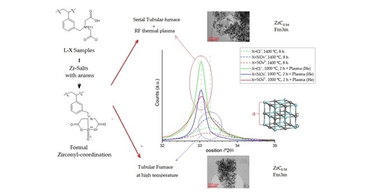
Nano-ZrO2@C, Nano-(ZrC, ZrO2)@C and Nano-ZrC@C Composites Prepared by Plasma-Assisted Carbonization of Zr-Loaded Iminodiacetate-Functionalized Styrene-Divinylbenzene Copolymers

1
Research Centre for Natural Sciences, Institute of Materials and Environmental Chemistry, Magyar Tudósok krt. 2, H-1117 Budapest, Hungary
2
Department of Physical Chemistry and Materials Science, Budapest University of Technology and Economics, Műegyetem rakpart 3, H-1111 Budapest, Hungary
3
Department of Organic Chemistry, Budapest University of Technology and Economics, Műegyetem rakpart 3, H-1111 Budapest, Hungary
4
Deuton-X Ltd., Selmeci u. 89, H-2030 Érd, Hungary
*
Author to whom correspondence should be addressed.
Inorganics 2022, 10(6), 77; https://doi.org/10.3390/inorganics10060077
Submission received: 21 April 2022 / Revised: 12 May 2022 / Accepted: 31 May 2022 / Published: 2 June 2022
(This article belongs to the Special Issue Plasma Application for Inorganic Synthesis and Analysis)

Abstract

:
We have developed an easy route to prepare (nano-ZrO2,nano-ZrCx)@C composites with varying ZrO2/ZrCx content. The process consists of preparing a zirconium-loaded, iminodiacetate-functionalized styrene-divinylbenzene (STY-DVB) copolymer, and its subsequent carbonization in a tube furnace and/or a thermal plasma reactor. Depending on the zirconium salt used (zirconyl chloride, zirconyl nitrate or zirconium (IV) sulfate) in the Zr loading, the Zr-loaded resins resulted in ZrO2@C pre-pyrolizates with C to Zr molar ratios of 5.8, 6.8 and 6.60. This carbon surplus is sufficient for the partial or even complete reduction of ZrO2 into ZrC0.58 at 1400 °C. The reaction products also contain 5 to 55 mass% residual free carbon. The plasma processing of the ZrO2@C composite formed at 1000 °C in a tube furnace led to ZrC0.94@C composites. The transformation of amorphous carbon content during the plasma treatment strongly depended on the atmosphere (He or H2) in the reactor and the anion type of the Zr salt. In the presence of He, amorphous carbon could be completely transformed into graphite. In the presence of H2, amorphous carbon and graphite were found at roughly the same ratio. No ZrO2 could be detected in the plasma-treated samples, whilst different ZrO2 polymorphs were found in the samples prepared in the tube furnace, depending on the synthesis conditions.

Graphical Abstract

1. Introduction

Composites containing zirconium carbide, amorphous carbon or graphite and some or no ZrO2 are important strategic materials for the nuclear industry due to their advantageous mechanical properties, neutron absorption cross-section and radiolytic stability [1,2,3,4]. A recently developed method of synthesizing (nano-ZrC,nano-ZrO2)@C composites is the high-temperature or plasma-assisted carbonization of Zr-loaded functionalized polymers. This can be achieved with polyacrylonitrile-ZrCl4 composites [3] and quaternary ammonium salt or styrene-divinylbenzene copolymers containing a sulfonate group and loaded with anionic [4] and cationic zirconium species [5], respectively, as precursors. The homogeneous distribution of the functional groups allows for zirconium to be bound at an atomic level, enhancing the distribution of ZrC in the carbon matrix after carbonization.
The chemical nature of functional groups (sulfonate or iminodiacetate) and DVB content in the STY-DVB copolymer have a significant influence on the chemical nature of metal compounds embedded in the carbon matrix during the carbonization of metal-loaded, functionalized, styrene-divinylbenzene (STY-DVB) copolymers, [6,7,8]. In fact, ZrC could be prepared by the carbonization of the quaternary ammonium group-containing and anionic Zr-loaded STY-DVB resins at 1350 °C [3], whereas only ZrO2@C composites were formed from the sulfonated resins [5]. Due to the moderate reactivity of ZrO2 in these composites, their subsequent RF plasma treatment in either a He or H2 atmosphere [5] only resulted in a partial conversion of ZrO2 into ZrC.
Our goal was to study the effect of functional groups on the formation and composition of zirconium carbide using STY-DVB copolymer precursors functionalized with groups that differed from sulfonate or quaternary ammonium. Since no information is available on the carbonization reactions of Zr-loaded iminodiacetate-functionalized STY-DVB resins, we studied the formation of ZrC in the carbonization process of these resins in both a tubular furnace and/or a thermal plasma-assisted process.
It is known that STY-DVB resins functionalized with iminodiacetate groups and loaded with a polyvalent element such as iron(III) have special properties due to the divalent selective iminodiacetate groups and the presence of a third, outer counter-ion neutralizing the third valence of iron(III) (X=Cl, nitrate or sulfate) [7,9,10]. Therefore, we conducted a detailed study of the influence of counter-ions such as chloride, nitrate, or sulfate on the chemical form of Zr in Zr-loaded iminodiacetate-functionalized STY/DVB copolymers.
Hereinafter, the prepared materials are referred to as L-X, L-Zr-X, L-Zr-X-T-t, where L stands for the Lewatite resin skeleton, X stands for the anion in the mineral acid or Zr salt used in H or Zr loading, respectively. T corresponds to the pyrolysis temperatures (1000, 1200, 1400 °C), whereas t represents reaction time (2 or 8 h). The L-Zr-X-1000-2 samples subjected to subsequent RF plasma processing in a H2 and He atmosphere were labeled as L-Zr-X-1000-2-P-H2/He, as summarized in Table 1. Sulfate and nitrate ions were given the abbreviations S and N, respectively, in the L-Zr-X, L-Zr-X-T-t and L-Zr-X-100-2-P-H2/He formulas.
In this paper, we present the preparation conditions and properties of nano-(ZrCx,ZrO2)@C composites made in a tube furnace (1000–1400 °C for 2–8 h) from Zr-loaded iminodiacetate-functionalized STY-DVB resins, and nano-ZrCx@C samples from L-Zr-X-1000-2 samples containing ZrO2. The method we used was RF thermal plasma treatment. We also conducted a detailed study of the chemical nature of Zr in the L-Zr-X samples, the number of iminodiacetate groups in the STY-DVB polymer chain, and the influence of the degree of Zr saturation and the anion of the Zr salt used during Zr loading on the properties of the forming nano-(ZrO2, ZrC)@C.

2. Results and Discussion

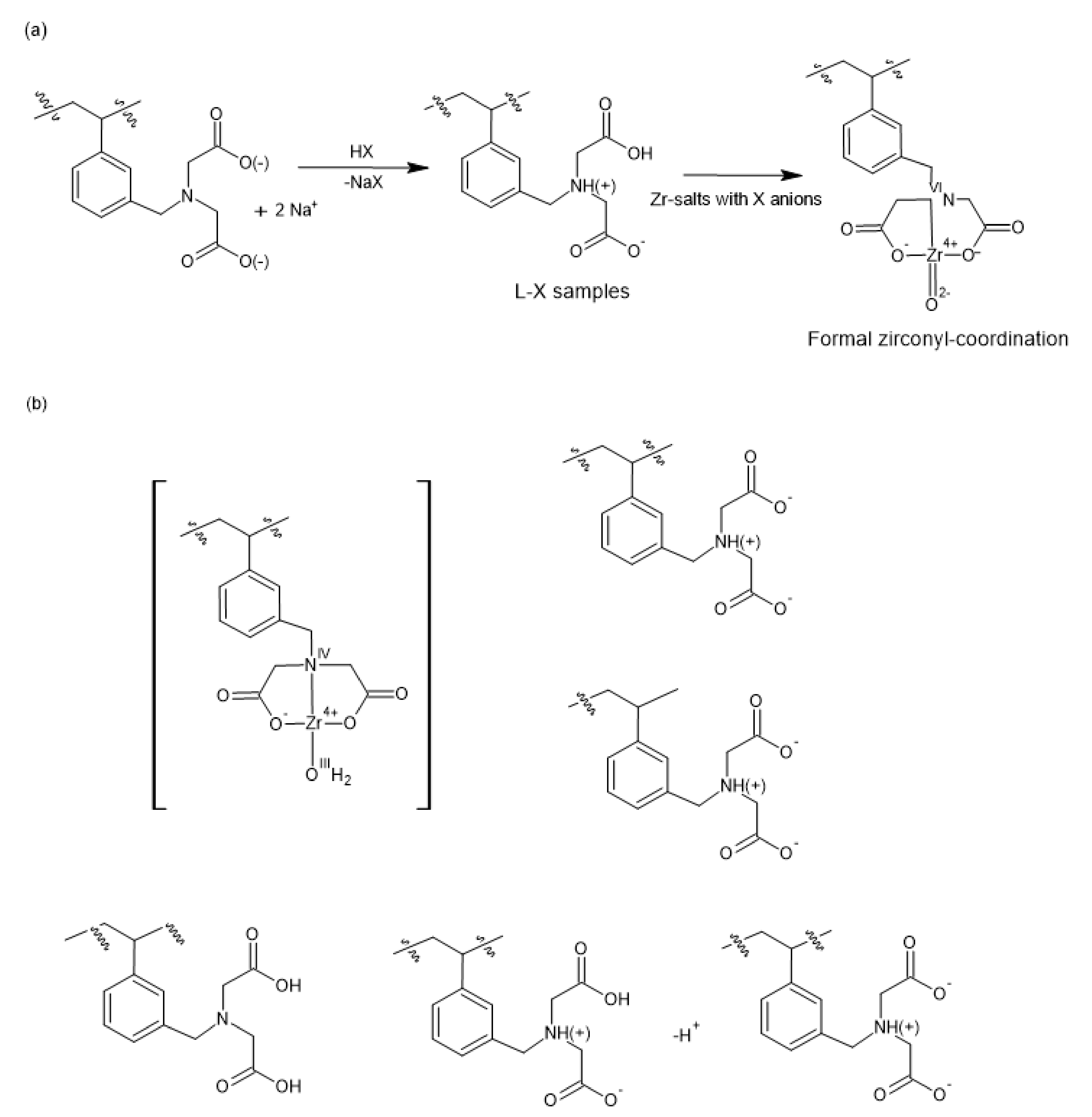
2.1. Preparation and Properties of Zr-Loaded Ion-Exchangers (L-Zr-X, X=Chloride (Cl), Nitrate (N) and Sulfate (S))

The iminodiacetate-functionalized styrene-divinylbenzene copolymer was prepared via chloromethylation of STY-DVB copolymer containing 2% DVB exclusively at the meta-position of STY rings [11] with subsequent coupling with iminodiacetic acid diethyl ester and by alkaline hydrolysis (ESI Scheme S1). The sodium salt of the resin containing the iminodiacetate group was activated with 10% HCl, HNO3 and H2SO4 (Scheme 1a), resulting in L-X resins as starting materials.
The Zr-loading of L-X resins was performed with zirconium salts containing X anions, namely 0.5% zirconyl chloride (ZrOCl2.8H2O in a 3 M HCl solution), 0.5% zirconyl nitrate (in 3 M HNO3) and 0.5% zirconium (IV) sulfate (in 1.5 M H2SO4) (Scheme 1a). Due to their acidic pH, the formal chemical species of zirconium (IV) was the “zirconyl” ion, ZrO2+ [12,13,14]. Therefore, the CHNS elemental analysis data of L-Zr-X resins, the zirconium content of the solution eluted during Zr loading, and the amounts of L-X resins/salts containing zirconium used provide sufficient information for the calculation of the Zr/iminodiacetate group ratio (loading rate), water content and the Zr/C ratios according to the method given by Dunlop CJ et al. [15] (Supplementary Materials, Table S1).
The ratio of N content (x mole of iminodiacetate is located on the DVB and STY rings) and carbon content (x mole of methylene-iminodiacetic acid groups and the polymer chain consisting of DVB and STY) suggests that almost exactly one -CH2N(CH2COO)22- group is located on every aromatic (STY or DVB) ring (Table S1). This means that during chloromethylation of the base polymer (STY-DVB) [16] (and consecutive coupling with iminodiacetic acid ester), only one chloromethyl group (iminodiacetate group) was inserted into every aromatic ring and, according to the synthesis conditions, it was built exclusively into the meta-position (see the IR results below and Supplementary Materials Figure S1) (Supplementary Materials, Scheme S1).
Knowing the ratio of STY/DVB/-CH2N(CH2COO)22- groups, we calculated the number of hydrogens belonging to these building elements. The ratio of Zr loading and the amount of iminodiacetate groups in L-Zr-X samples was easy to calculate from the molar ratio of nitrogen and zirconium contents. Zr loading was 34.8%, 27.0% and 22.8% for the samples produced from zirconyl chloride, zirconyl nitrate and zirconium (IV) sulfate, respectively. The difference between the calculated and measured hydrogen content may be attributed to the presence of swelling water, whose amounts were around ~20% (Supplementary Materials Table S1).

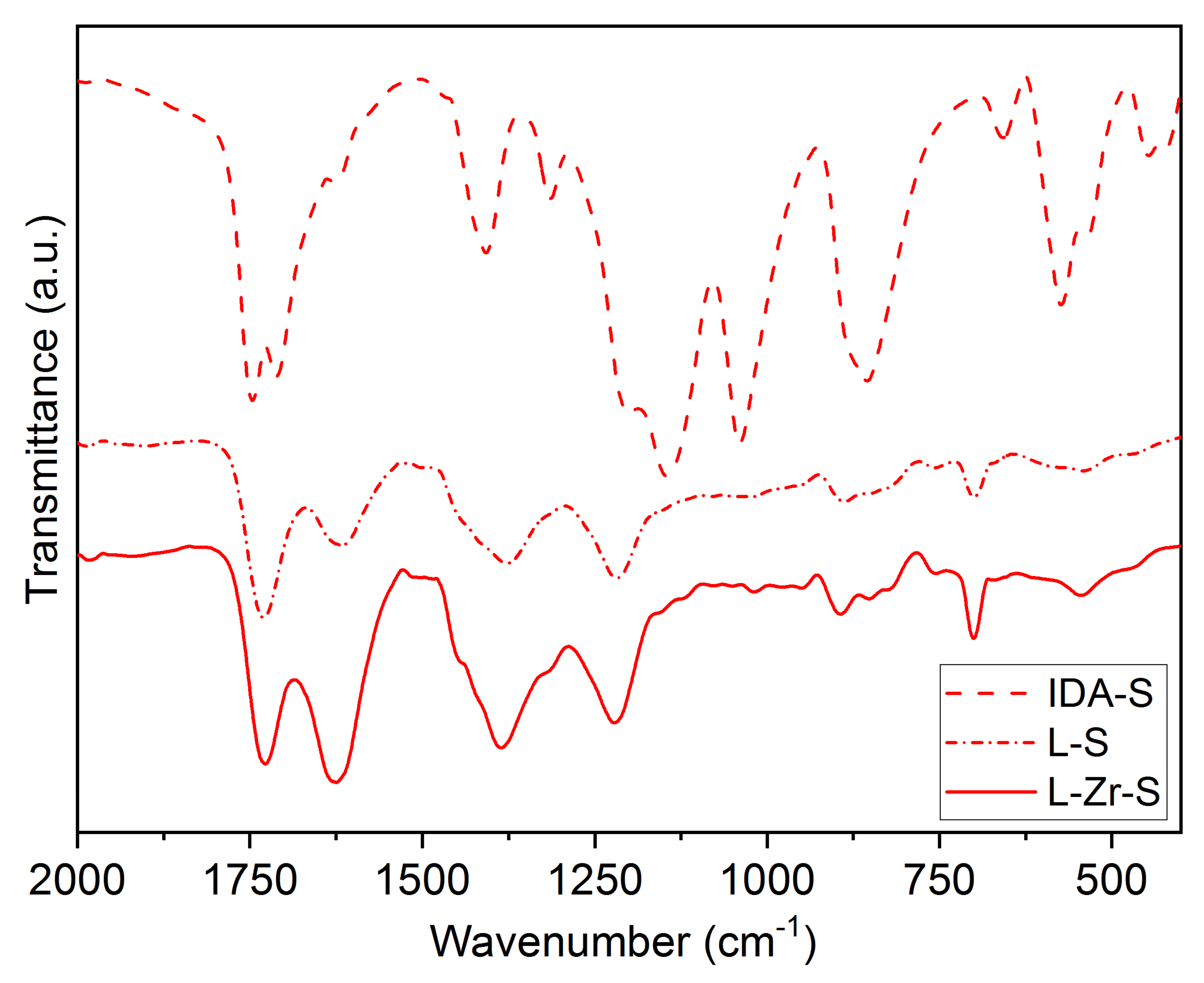
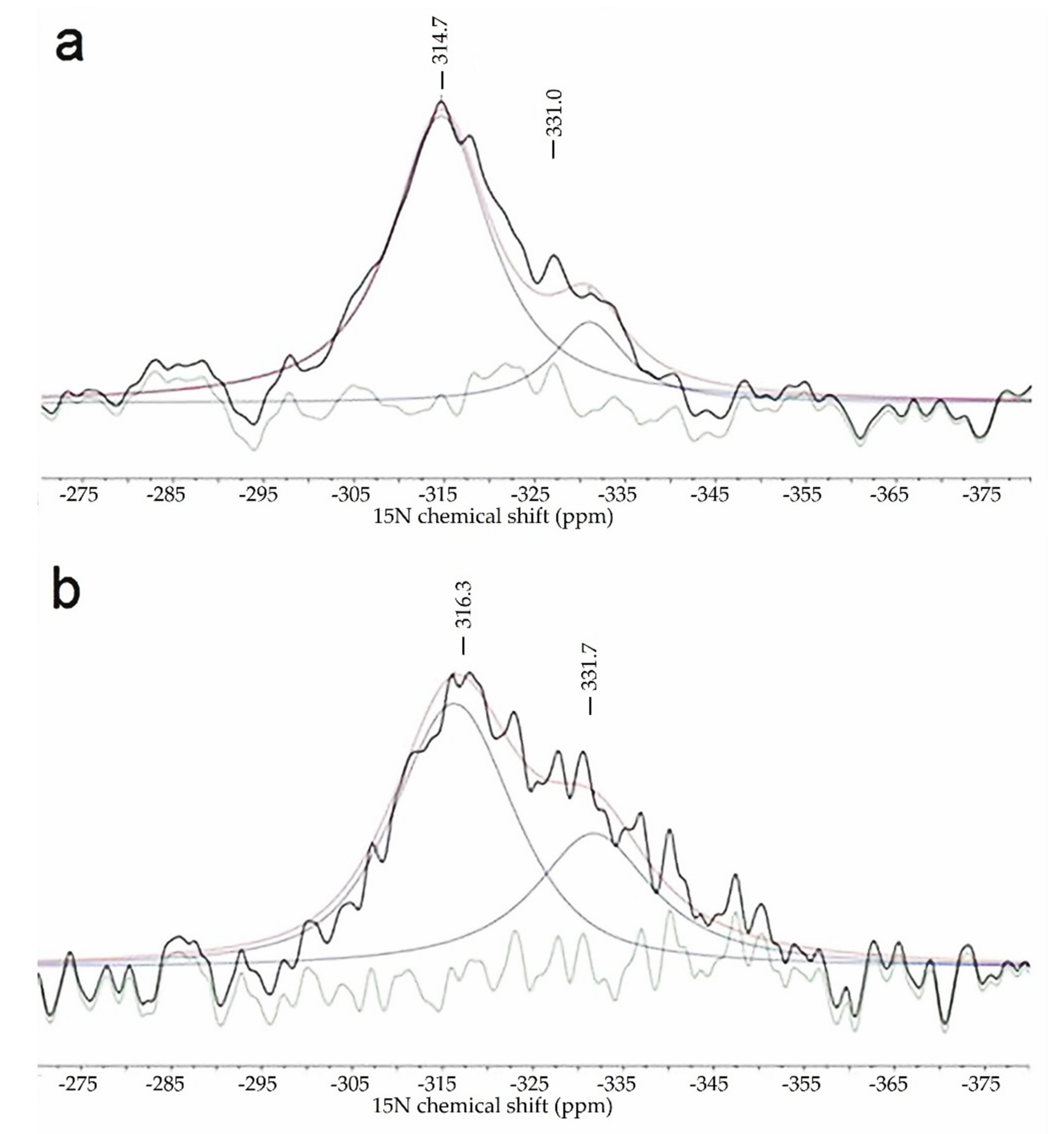
2.2. The Chemical Nature of Zirconium in the L-Zr-X Samples

The chelate-forming ability of the iminodiacetate group resulting in the coordination of a nitrogen lonely electron pair to the zirconium d orbitals stabilizes the chelate structure. In this way, the protonation possibility of a tertiary nitrogen atom with HX acids in the chelate ring is lost. Therefore, the presence of foreign anions (chloride, nitrate and sulfate) due to the protonation of tertiary N atoms cannot be expected. The iminodiacetate group is a divalent-ion selective group; thus, one iminodiacetate group neutralizes only two charges of a multivalent cation, and one or more foreign ions neutralize the surplus charges, as was observed in the case of L-Fe-X complexes containing Fe(III) ions [6,7,8,9]. In principle, the counter-ions in the salts used for Zr loading (chloride, nitrate or sulfate) may neutralize foreign anions. However, the elemental analysis data and IR spectroscopy results on L-Zr-X compounds show the absence of any foreign anion; thus, the tertiary amino group of the -CH2N(CH2COOH)2 part must be self-protonated with one of its carboxylic acid group (-CH2NH(CH2COO)(CH2COOH) (Scheme 1b)).
The almost identical N content in the three L-Zr-X samples or the lack of sulfur indicates the absence of nitrate or sulfate anions (Supplementary Materials, Table S1). The matching IR patterns for L-Zr-X samples (X=Cl, N and S, Supplementary Materials, Figure S2) confirm that the chemical nature of these samples is practically the same. Most of the sulfate and nitrate IR bands would coincide with the IR bands of the iminodiacetate group and STY-DVB skeleton. A comparison of the IR spectra of the HCl, HNO3 and H2SO4 salts of the iminodiacetic acid (Supplementary Materials, Figure S3) and L-Zr-Cl (Supplementary Materials, Figure S2) resins showed that the νas(S-O) and νd(N-O) modes of sulfate and nitrate ions could be identified in the IR spectra of [HN(CH2COOH)2].HX (X=NO3 and ½SO4) salts as a doublet at 1143/1042 cm−1 and a singlet at 1057 cm−1, respectively. These bands should appear in these spectral ranges to show the presence of sulfate and nitrate ions in the IR spectra of L-X and L-Zr-X resins if the tertiary N atom of the iminodiacetate fragment is protonated with the HX (X=N or S) acids.
However, a comparison of the L-X and L-Zr-X compounds (Supplementary Materials, Figures S4–S6) showed that neither the L-X compounds nor the L-Zr-X compounds contain foreign anions (Cl-, NO3- or SO42-). The presence of the Zr=O group or its hydrated form (Zr(OH)2) with oxide- or hydroxide-neutralizing anions cannot be confirmed because of the absence of a strong and wide band at 1020–870 cm−1 characterizing the zirconyl ion [14,15,16,17]. Yuchi et al., assumed the presence of Zr species of the type L-Zr(OH)2 in a Zr-saturated IDA resin, but we did not observe any strong and sharp bands of ionic OH [17,18] above 3500 cm−1 in the IR spectra of our L-Zr-X resins (Figure 1). Therefore, a similar chemical environment of the N atom is expected in all six L-X and L-Zr-X (X=Cl, N and S) compounds.
The IR spectra of L-X and L-Zr-X resins showed the typical C-H (aromatic and aliphatic) and C-C (aromatic ring) and other vibrational modes of the polystyrene-divinylbenzene copolymers [5,19,20], and the typical normal modes of iminodiacetate groups as well [21]. The evaluation of the spectra imposes a challenge due to the substantial overlaps of the polystyrene network and iminodiacetate group modes. The most critical peaks agree with the reference values [5,14,22,23,24,25,26,27,28] given for polystyrene-DVB samples. There is no peak at 1680 cm−1 associated with the free vinyl groups of the crosslinker. Thus, there are no pendant vinyl groups in the samples. The lack of a peak at 833 cm−1 and the steric hindrance of the ortho positions due to the steric demand of iminodiacetate groups confirm the meta-substitutions on the STY rings [24].
Even when we used a significant excess of zirconium salt, we could not saturate the iminodiacetate groups—the ratio of uncomplexed/chelated iminodiacetate groups in the L-Zr-X samples was ~2:1, ~3:1 and ~4:1 for X=Cl, N and S, respectively. Since the iminodiacetic acid groups forming in the acidic environment during Zr loading rearrange into an N-protonated form with the formation of a carboxylate group, a “free” iminodiacetic group can act as a monovalent acid. It can be considered as only a monovalent anion, [HN(CH2COO)2]-. Thus, the counter-ions of zirconium (IV) used to neutralize the excess of two charges of zirconium (IV) may be two ionic unchelated iminodiacetate groups (Scheme 1b). Due to intramolecular self-protonation, a minimum of two free iminodiacetate groups need to neutralize one chelated iminodiacetate-coordinated zirconium. Thus, the Zr-loading of iminodiacetate groups in the L-Zr-X samples may not be higher than 1/3 due to the 2:1 ratio of monovalent anionic and chelated iminodiacetate groups, respectively, as was found in the case of the zirconyl chloride-loaded L-Zr-Cl sample (Scheme 1b).
To confirm the presence of the protonated/Zr-coordinated nitrogen atoms in the L-Zr-X samples, we used solid-state 15N and 13C CP MAS NMR spectroscopy. Deconvolution of the broad 15N CP-MAS NMR signal of the iminodiacetate nitrogen resulted in two components for both samples, L-N and L-Zr-N (315/330 and 317/332 ppm, Figure 2a,b, respectively). The signal at 315 ppm may be attributed to the protonated N-atom, whereas the signal at 317 ppm can be attributed to the protonated and Zr-coordinated N-atom. This latter signal is broadened by the quadrupolar magnetic nature of the Zr. A weak 15N signal of the unprotonated tertiary N atom (due to the equilibrium character of the protonation reaction) also appears in both spectra.
The chemical shifts in the nitrogen atoms in protonated and coordinated forms (Scheme 1b) are similar—the electron-shielding environment is similar. In other words, the strength of the coordination of Zr to the nitrogen atom in the iminodiacetate group of L-Zr-X samples is close to the strength of the proton binding to the protonated nitrogen atoms in -HN(CH2COOH)(CH2COO) or -HN(CH2COO)2- groups (Scheme 1b).
When X= sulfate and nitrate, the chelated/unchelated iminodiacetate group ratios were 1:4 and 1:3, respectively. The free iminodiacetate groups are in their acidic form according to the low pH used during Zr loading and, due to self-protonation, these are in the [-CH2-NH(CH2COO)(CH2COOH) (Scheme 1b) form [29]. The asymmetric nature of these iminodiacetate groups results in two C=O carbonyl signals [28] in the 13C NMR spectra of the L-X-Zr samples (Supplementary Materials, Figure S7).
Due to the lack of foreign neutralizing ions in the L-Zr-X samples, a question arises: why is Zr loading so different depending on the chemical form of the zirconium salt used in the loading experiments?
The zirconium(IV) ion easily hydrolyzes/polymerizes in aqueous solutions, even under highly acidic conditions [12]. The exclusive form of zirconium(IV) in aq. solutions above pH > 0 are zirconyl ions (ZrO2+), but the counter-ions have an enormous influence on the chemical nature of the species containing Zr. For example, solid zirconyl nitrate, ZrO(NO3)2∙5H2O, consists of H2[ZrO(NO3)4].H2O anionic species. It completely dissociates in its aqueous solutions with the formation of a neutral ZrO(OH)NO3, which could not be loaded on a cationic (Amberlite IR 100) ion exchanger [13].
Zirconium sulfate strongly hydrolyzes in water. Basic zirconium sulfates are formed, including zirconyl sulfate, given the affinity of zirconium to sulfate, which is higher than the affinity to water. Thus, the sulfate ion is bound to zirconium strongly even in aq. solutions. For example, the electrolysis of aqueous Zr(SO4)2 solutions results in hydrogen evolution on the cathode, and H2[ZrO(SO4)2∙3H2O] was identified in the solution [30], which contains the zirconium in an anionic species.
Solid zirconyl chloride (ZrOCl2.8H2O) is a tetramer, [Zr4(OH)8(H2O)16]Cl8 [12], and the zirconyl ion is the dominant form in its aqueous solutions. Zirconium (IV) ions would form only in >12 M HCl solutions and at a very low (0.0001 M) zirconium concentration [12]. We used a 0.055 M zirconyl chloride solution in 10% aq. HCl, thus, this solution contained only ZrO2+ and not Zr4+ ions.
The solution-phase zirconium species form complex equilibriums with the resin-phase iminodiacetate group. The difference between the chemical forms of zirconium in the solutions of the three zirconium salts may be attributed to the differences in Zr loading on the L-X resin under identical Zr loading conditions.

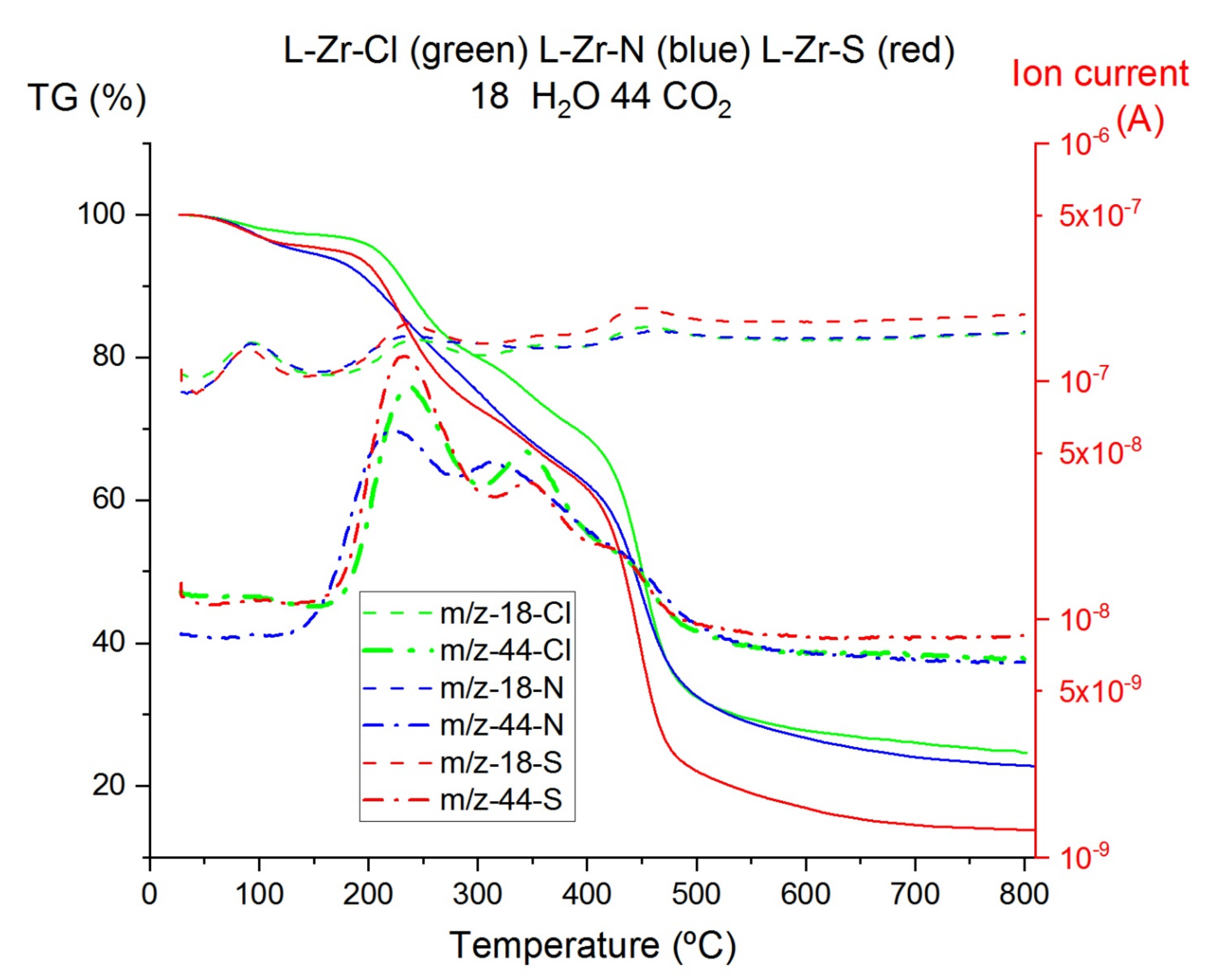
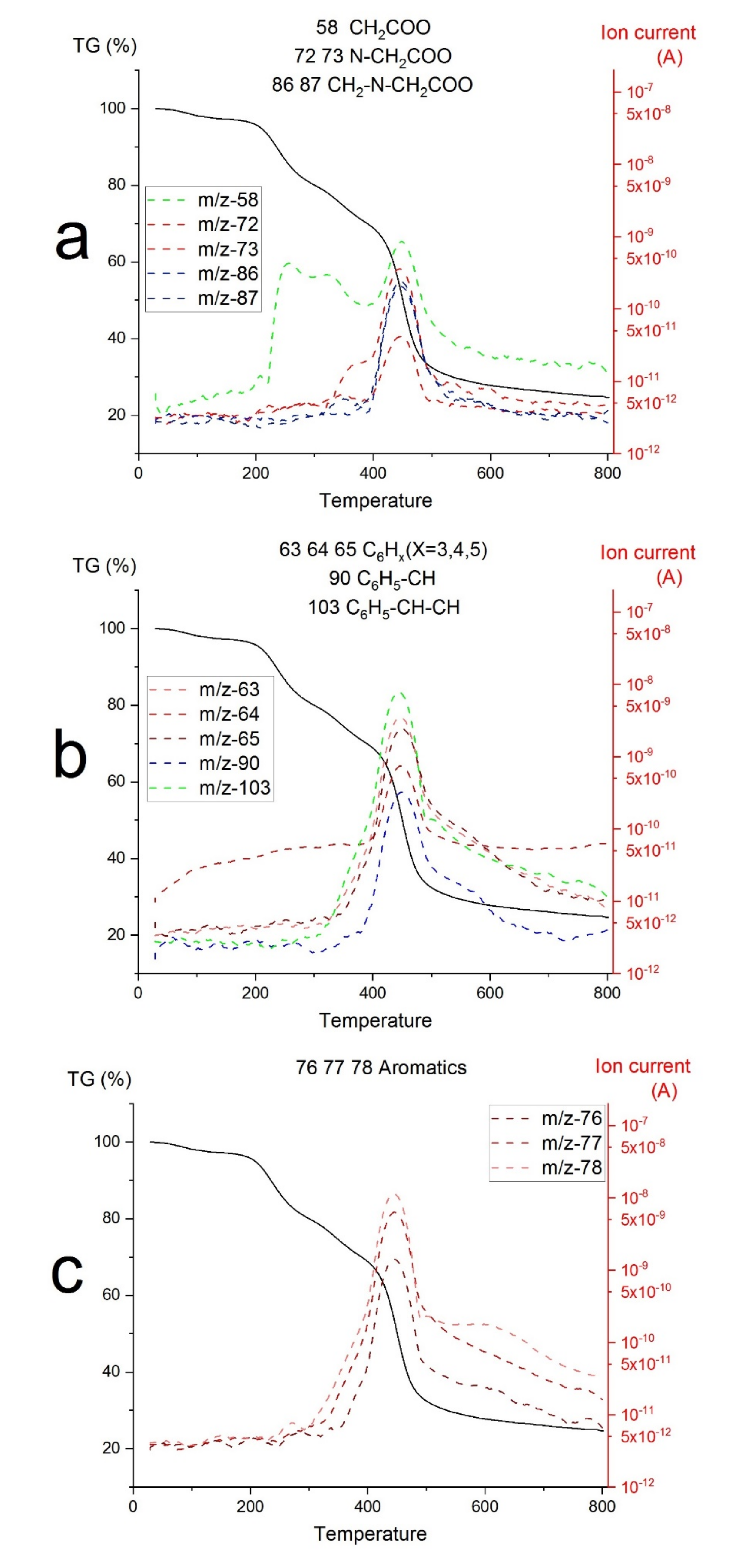
2.3. Thermal Studies on Compounds L-Zr-X

During the heat-induced carbonization of STY-DVB copolymers—with or without functionalization with functional groups—a part of the carbon content turns into volatile compounds such as hydrocarbons and the cracking products of the functional groups [6,9]. The iminodiacetate group is expected to be cracked into fragments of the CH2N(CH2COOH)2 group, including H2O (from dehydration) or CO2 (from decarboxylation) and various fragments containing N [31]. The evolution of H2O, CO2, STY, DVB, some aromatic hydrocarbons, and the expected fragmentation products of the iminodiacetate group containing N is illustrated as a function of temperature (Figure 3 and Figure 4 and Supplementary Materials, Figures S8–S10).
The ratio of solid to volatile carbon compounds strongly depends on the decomposition temperature, heating rate, and DVB content and is influenced by the presence of metal ions and the extent of metal loading [6,9]. Generally, the higher the metal or DVB content, the more solid carbon products are formed [6,32,33,34]. Either the 2% DVB content or the incomplete saturation of functional groups by zirconium is a favorable condition for low solid carbon content in the decomposition products [5,6], increasing the Zr/C ratio in the carbonized material. Therefore, first, we studied the mass loss ratio of volatiles (H2O, CO2, and organic decomposition products)/solids (ZrC, ZrO2 and carbon) at 800 and 1400 °C. The measured C/ZrO2 ratios in the pre-pyrolyzed products of L-Zr-X samples formed at 800 °C (after eliminating all organic volatiles) were ~5.8, ~6.8 and 6.64 for X=Cl, N and S, respectively. Thus, the C/Zr ratio ensures that there is enough carbon content to form ZrC from ZrO2/C intermediates. The free carbon contents of the decomposition products formed at 1400 °with a 10 °C/min heating rate were ~10, ~5 and ~45 mass% for the composites prepared from L-Zr-X resins (X=Cl, N and S), respectively.
The thermal decomposition of the L-Zr-X samples (X=Cl, N and S) started similarly, by losing the swelling water and some adsorbed organic materials from the pores of the hydrophilic STY-DVB polymer network below 200 °C (Figure 3). The TG-MS curves first showed the elimination of water. Loss of the iminodiacetate functional groups occurred with the evolution of CO2, H2O and CH2COO fragments (Figure 3 and Figure 4, Supplementary Materials, Figures S8 and S9) at around ~220 and ~320 °C. Depolymerization first occurred around ~320 °C, with the formation of STY and DVB. Complete cracking of the organic residues occurred with the formation of aromatic compounds between 400 and 500 °C. The TG-MS curves of decarboxylation, dehydration, depolymerization and cracking are given for L-Zr-X samples in Figure 4 and Supplementary Materials, Figures S8 and S9. The TG-DSC curves of the L-Zr-X systems are attached as Supplementary Materials, Figure S10.
Water elimination, depolymerization and cracking are endothermic, whereas the decomposition of the iminodiacetate functional groups was exothermic for L-Zr-X (X=Cl, N) samples. For X=S, all when the lower amount of Zr is adsorbed on the resin, all the reactions are endothermic (Supplementary Materials, Figure S8a–c). For X=N, zirconium carbide formed as an endothermic process, starting at 1180 and completed at 1321 °C.

2.4. The Composition of Carbonization Products

Carbonization was first studied in a tubular furnace at 1000, 1200 and 1400 °C for 2 h. The effect of reaction time was examined at 1400 °C—holding time was increased up to 8 h. Orthorhombic and tetragonal ZrO2 were detected as primary decomposition products at 1000 °C. The orthorhombic/tetragonal ratio strongly depended on Zr loading and was 1.36, 0.77 and 0 for the samples with X=Cl, N and S, respectively. Furthermore, the crystallite sizes of ZrO2 particles ranged between 5 and 10 nm for these samples (Table 2).
As carbonization temperature was increased to 1200 °C, a cubic ZrC0.58 (a = 4.6690 Å, Fm3m) appeared as the main reaction product (75, 65 and 50 mass% ZrC and 15, 25 and 10 mass% ZrO2 content for X=Cl, N and S, with a crystallite size of ~10 nm in every case (Table 2)). The exact composition of ZrC was calculated from the lattice constants determined by XRD (Figure 5 and Supplementary Materials, Figure S11), with the Gusev equation [35], which was valid for ZrCx samples with 0.5 < x < 1.0. Senczyk’s equation [36] valid for samples 0.65 < x < 01.0 did not give results in this range, which shows that x is out of the validity range of the equation. Residual amorphous carbon content would be enough to form stoichiometric ZrC by incorporating carbon into the ZrC0.58 structure at high-temperature heat treatment [37,38]. Thus, two sets of heat-treatment tests were carried out at 1400 °C with treatment times of 2 h and 8 h, and an RF plasma treatment was also performed in an H2 and He atmosphere on nano-ZrO2@C samples with Zr/C atomic ratios of ~5.8, ~6.8 and 6.64.
The heating time of 2 h at 1400 °C resulted in ZrC0.58@C (X=N) and (ZrC0.58,ZrO2)@C composites with a ZrC0.58/ZrO2 molar ratio of 8 and 2 (Table 2). ZrO2 was only detected as its tetragonal modification in these samples. Increasing the heating time to 8 h resulted in an increasing ZrC0.58 content and a partial transformation of ZrO2 into its monoclinic form (the tetragonal/monoclinic ratio was 2 and 5 for X=Cl and S, respectively). The crystallite sizes of ZrC0.58 ranged between 10 and 20 nm. Neither graphite nor Zr3C2 was found in these samples. Even under prolonged heating, additional carbon atoms were not incorporated into the ZrC0.58 structure. The reactivity of ZrO2 and carbon species in composites prepared from various Zr-loaded resins with various zirconium content was different in the carbonization reactions, despite the lack of foreign anions in the L-Zr-X samples. Therefore, we studied the behavior of all three L-Zr-X-1000-2 composites (containing ZrO2) (X=Cl, N and S) in RF plasma under an inert (He) and a reducing (H2) atmosphere.
Due to the high temperature that prevailed in the RF thermal plasma, the carbonization reaction between the ZrO2 and C species took place rapidly and zirconium carbide crystallized with a composition of ZrC0.94 (a = 4.6930, Fm3m) could be prepared. The ZrC stoichiometry in ZrCx was determined from the lattice constants of the particular samples (Figure 5) with the Senczyk equation [36]. The composition of samples did not depend on the counter-ion of the loading Zr salt, but the amount of ZrC/amorphous carbon/graphite ratio strongly depended on this.
The main features of ZrC0.94@C samples are the complete transformation of ZrO2 into ZrC. The amorphous carbon is expected to transform into graphite during the plasma treatment [37]. The average size of ZrC crystallites ranged between 35 and 62 nm, which is higher than that of the samples made in a tube furnace. This may be attributed to the effect of high temperature, resulting in fast diffusion and growing crystallites.
In general, the low DVB content (2%) of L-Zr-X samples resulted in a relatively high ratio of organic volatiles during carbonization, resulting in high ZrO2/C and high ZrC/C ratios in the precursor and product samples. The incorporation of iminodiacetate functional groups for Zr loading instead of sulfonyl groups [37] increased ZrC content in the ZrC@C composites. The composition of ZrC in the RF plasma-treated samples was almost the same, Zr0.93 and Zr0.94, for the samples prepared from sulfonated [37] and iminodiacetate-loaded resins, respectively. However, the ZrC0.94 content and ZrC0.94/ZrO2 ratio were far higher in the case of iminodiacetate-loaded than the sulfonated resins [37].

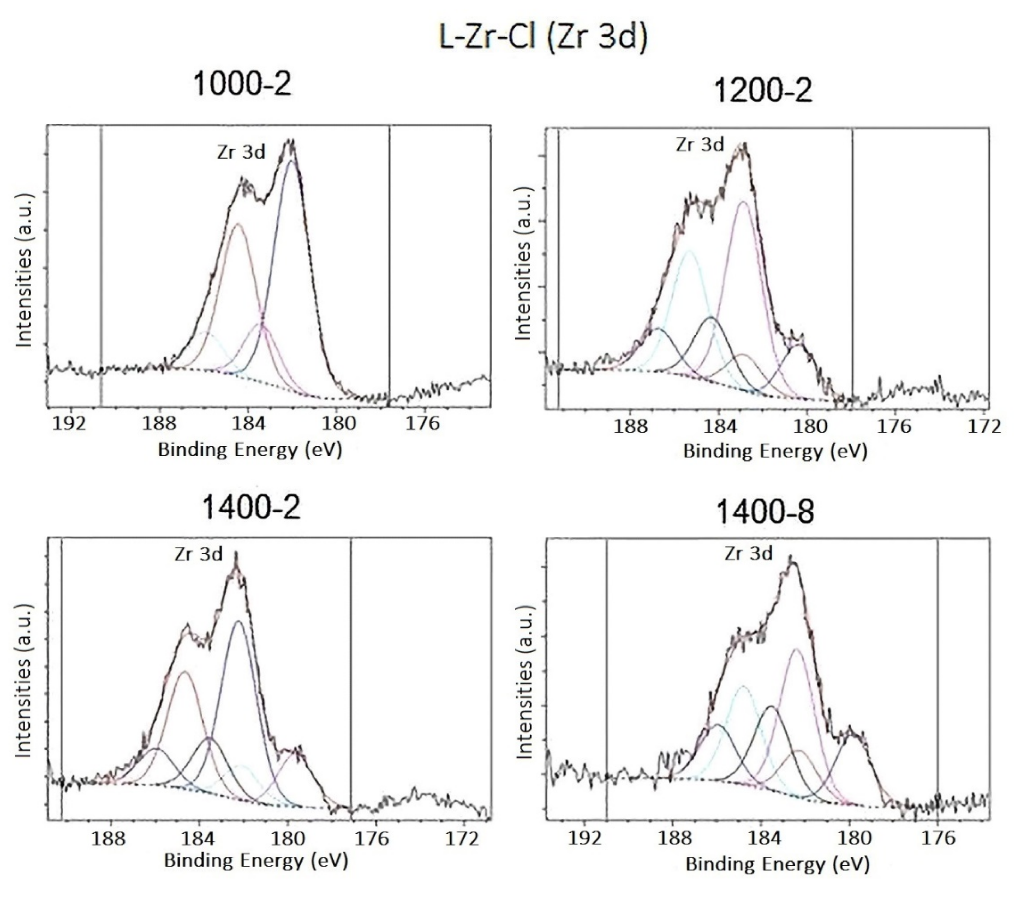
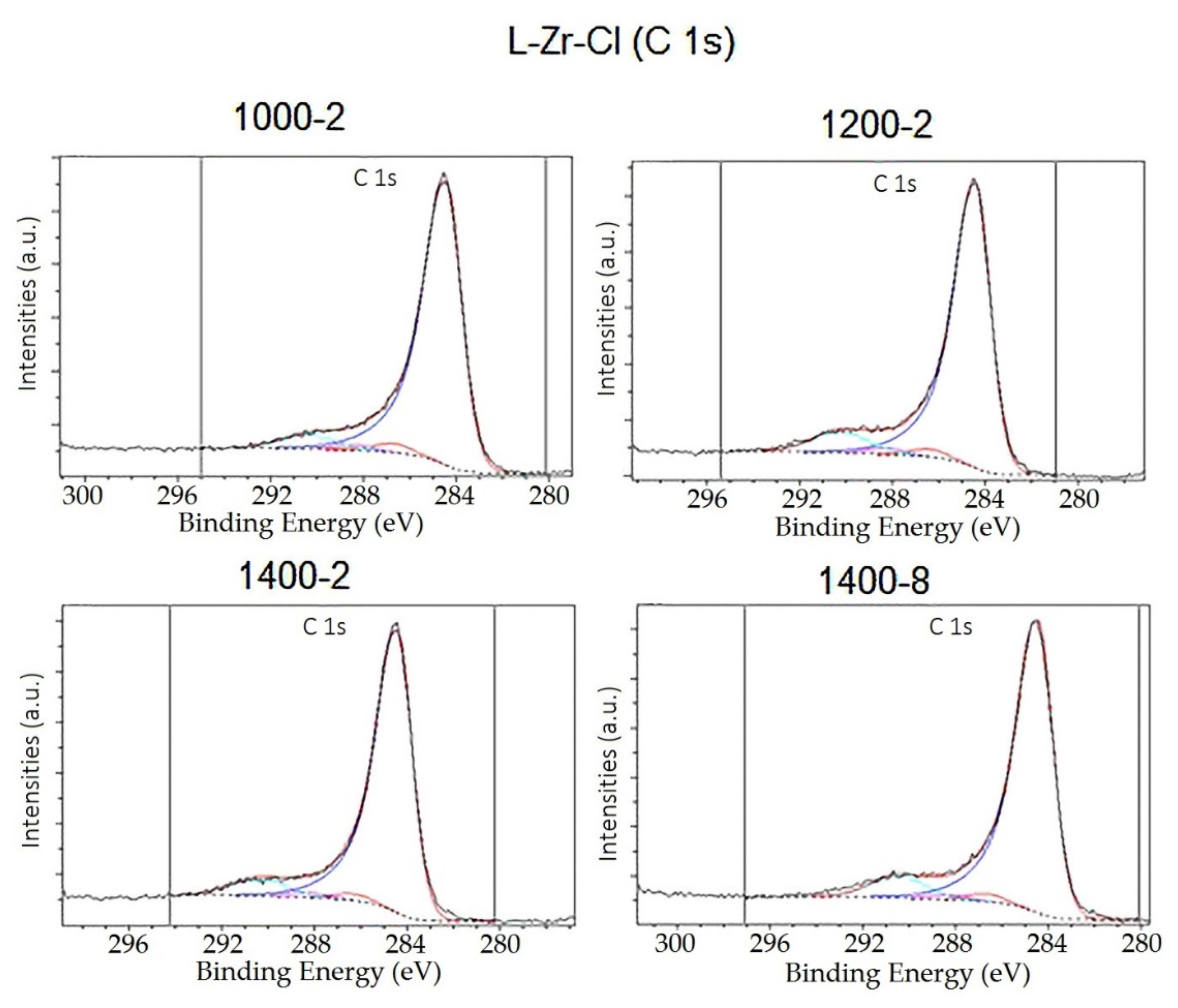
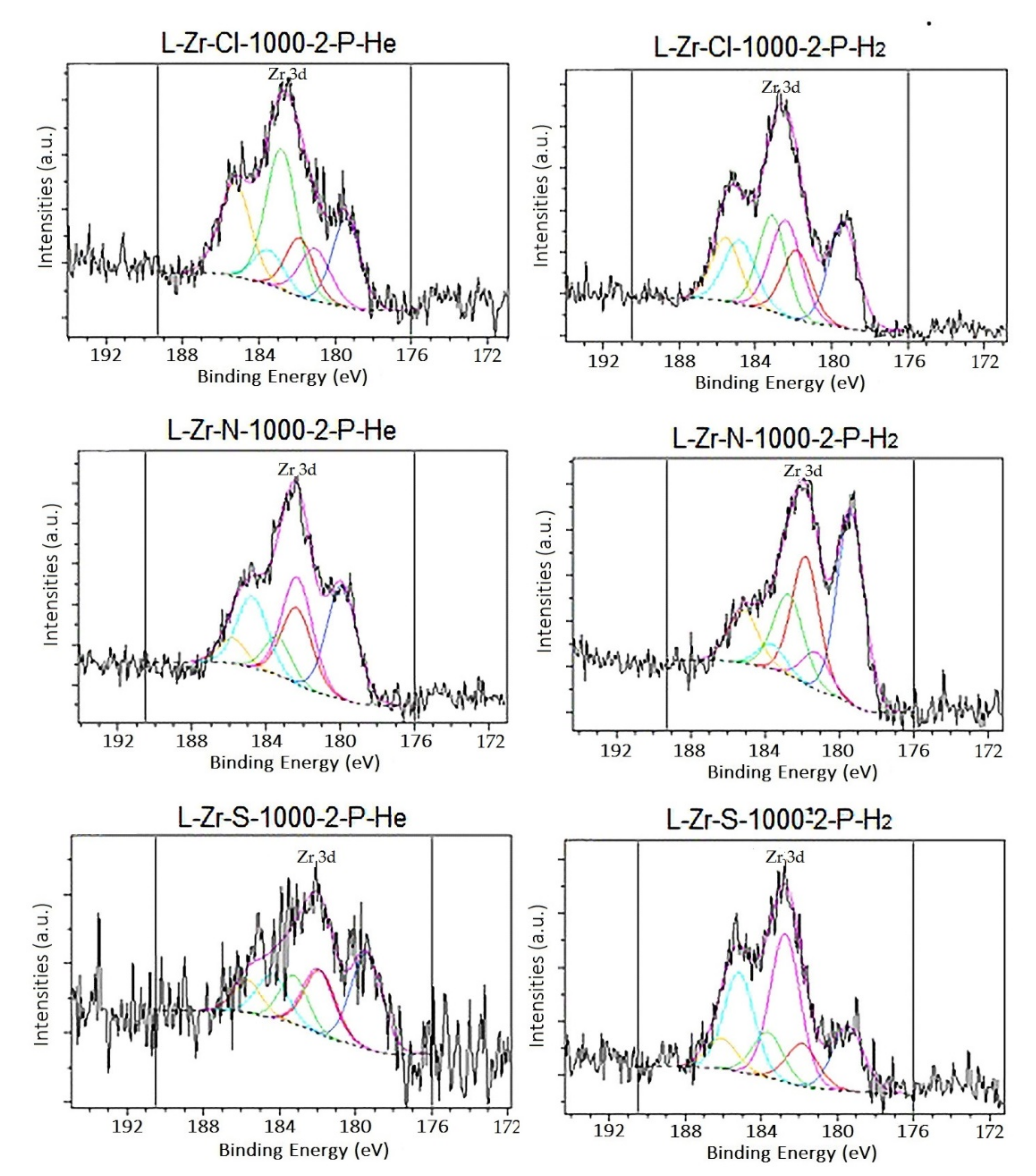
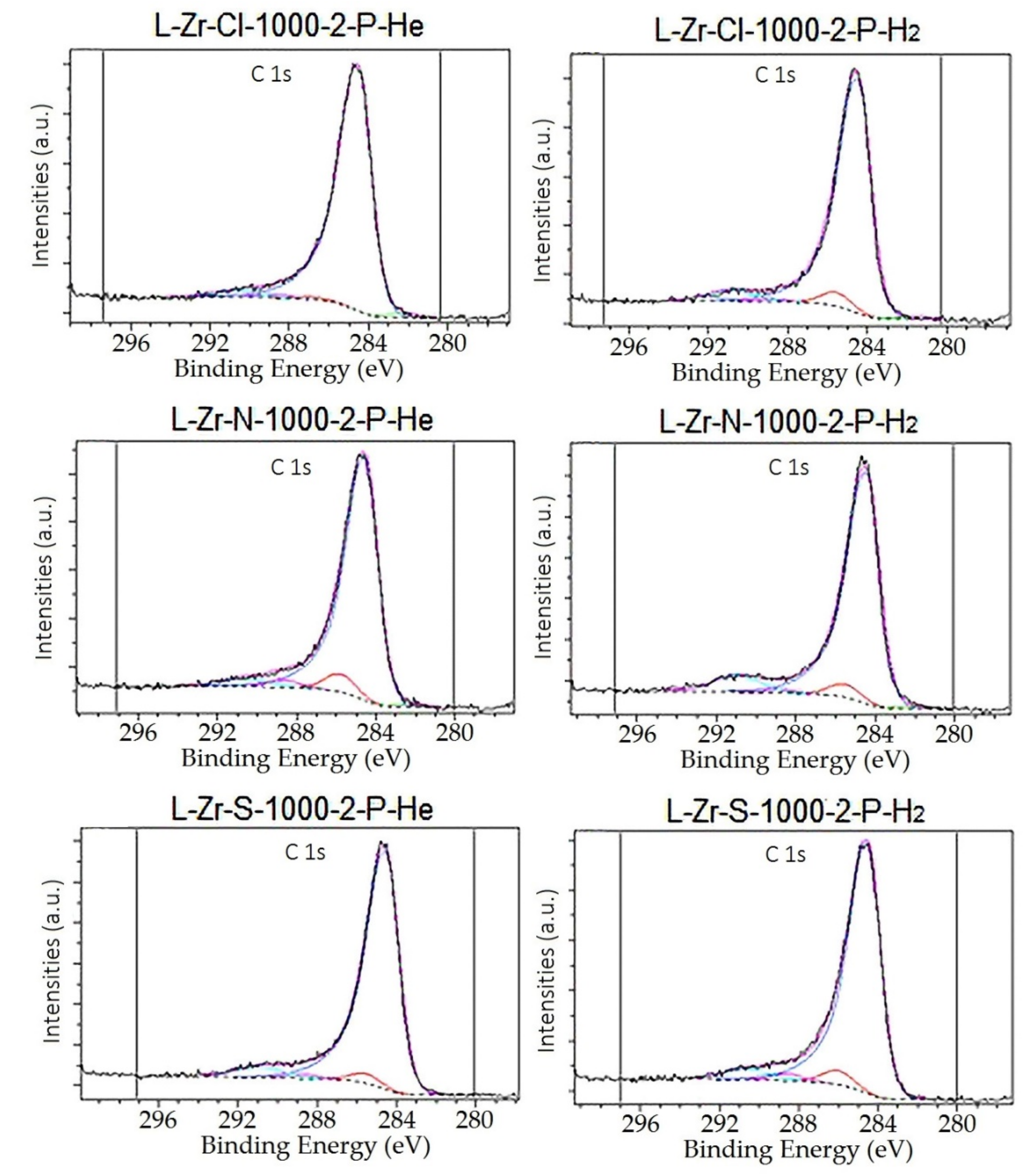
2.5. Surface Characterization of the Carbon Composites Containing Nano-ZrO2 and Nano-ZrC

We characterized the surface of the carbonized samples containing carbon balls decorated with nano-ZrO2 polymorphs, nano-ZrC or their mixture by N2 BET surface area analysis (Table 2 and Table 3), X-ray photoelectron spectroscopy (XPS) and high-resolution transmission electron microscopy (HRTEM). The surface area of nano-ZrO2@C composites prepared at 1000 °C for 2 h was 140, 278 and 33 m2/g for the samples with X=Cl, N and S, respectively. We found the same tendency for the samples containing ZrC and ZrO2 + ZrC prepared in a tubular furnace as the ZrO2@C samples. The highest values were found for X=N and the lowest values for X=S. Increasing the temperature from 1200 to 1400 °C had no critical effect on the surface area, whereas heating time (8 h instead of 2 h at 1400 °C) only had a considerable influence in the case of the X=Cl resin. The plasma treatment brought about significant sintering, resulting in a decreased surface area (Table 3).
The surface composition of some nano-ZrO2@C, nano-(ZrC0.58, ZrO2)@C and nano-ZrC0.94@C composites were determined by XPS, and the Zr3d, C1s and O1s spectra are given in Figure 6, Figure 7, Figure 8 and Figure 9 and Supplementary Materials, Figures S12 and S13. The calculated surface concentrations are given in Supplementary Materials, Tables S2–S5.
The surface of the L-Zr-X-T-t samples with X=Cl and S contains approximately 85–95% graphite. Zr0.58C (Zr3d5 BE ≈ 179.9 ± 0.5 eV) was found only in samples heated above 1200 °C in low concentration, but its presence was undoubtedly detected based on the zirconium spectra (Figure 6). Increasing the temperature to 1400 °C or applying prolonged heating had no significant effect on the concentration of ZrC on the surface. The surface concentration of ZrC in the L-Zr-Cl samples is approximately double that of the L-Zr-S samples. Zirconium was present in the samples in two other forms: ZrO2 (Zr3d5 BE ≈ 183.8 ± 0.5 eV) and presumably some kind of zirconium oxycarbide (Zr3d5 BE ≈ 182.5 ± 0.5 eV) (Tables S2 and S3, Figure 6, Figure 7, Figure 8 and Figure 9, Supplementary Materials, Figures S12 and S13). Oxidized carbon derivatives are also detectable on the surface in a few percentages. The line positions of the corresponding oxygen, O1s 531.2 eV and carbon, C1s 182.0 eV agreed with the literature data [39]. The appearance of the ZrO2 minor phase can be attributed to the high affinity between Zr and O [37,38]. Some of the oxygen is chemically bound to carbon (O1s 533.0 ± 0.2 eV, C1s 286.7 ± 0.2 eV). In the carbon spectra, the quantity of the oxidized carbon species can only be determined with an error due to the presence of the high graphite peak. The graphite peak was fitted with an asymmetric peak shape with AS(40;0.6) parameters. π-π* satellites were also present in the spectra at a binding energy of approximately 290 eV. Chlorine or sulfur could not be detected in the L-Zr-Cl-T-t and L-Zr-S-T-t samples.
The surface of RF-plasma-treated samples also contained 80–90 atomic% graphite and 1–8 atomic% ZrC0.94. The quantity of ZrC0.94 is the highest in the L-Zr-N samples and the lowest in the L-Zr-S samples. In the case of H2 plasma treatment, the surface ZrC0.94 contents are always higher than in the case of He plasma treatment. The ZrC0.94 content vs. the zirconium oxide content on the surface is the highest in the L-Zr-N samples. ZrO2 and zirconium oxycarbide concentrations varied between 2 and 11 atomic% (Supplementary Materials, Table S5), and a low percentage of oxidized carbon derivatives were also detected.

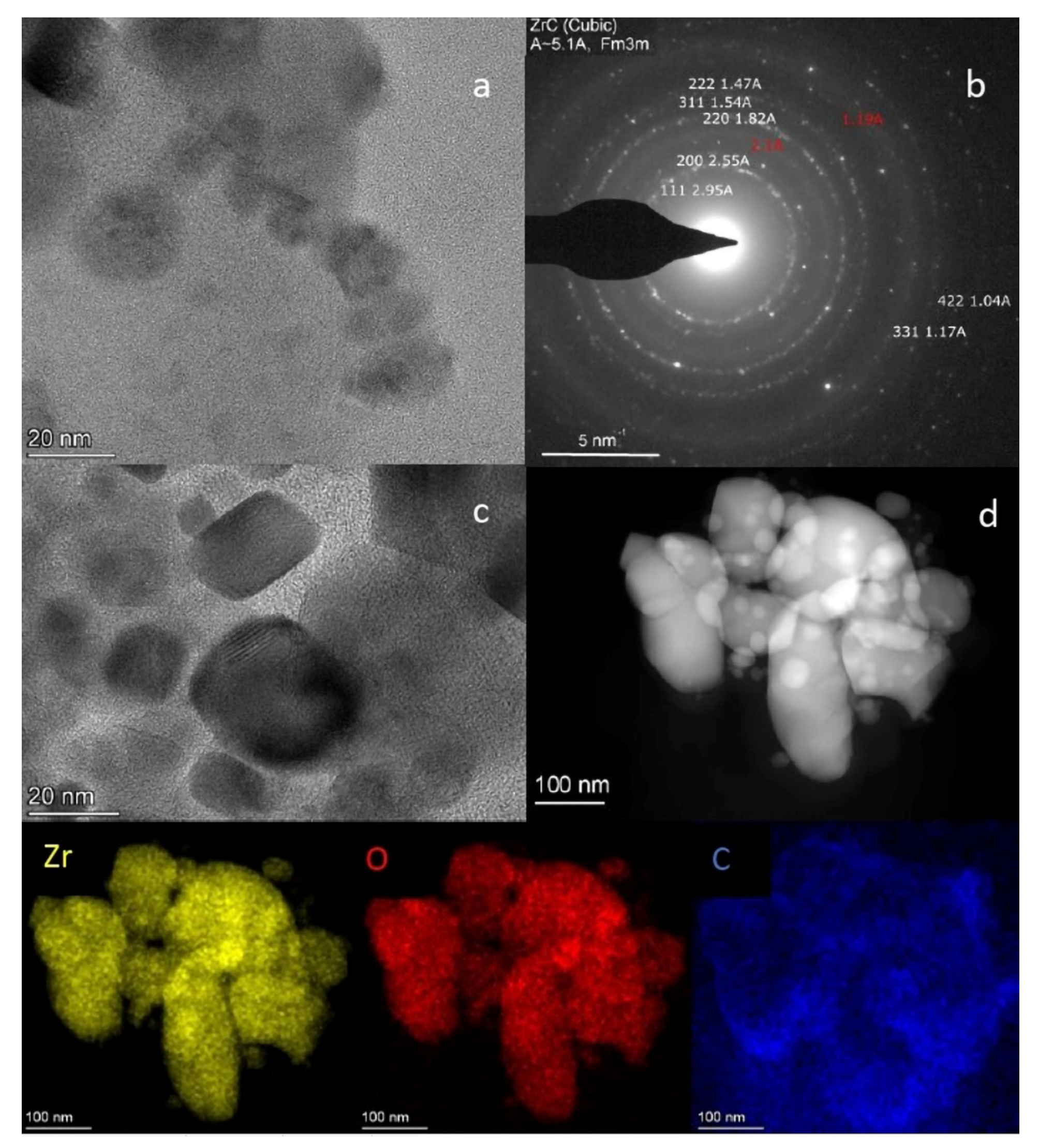
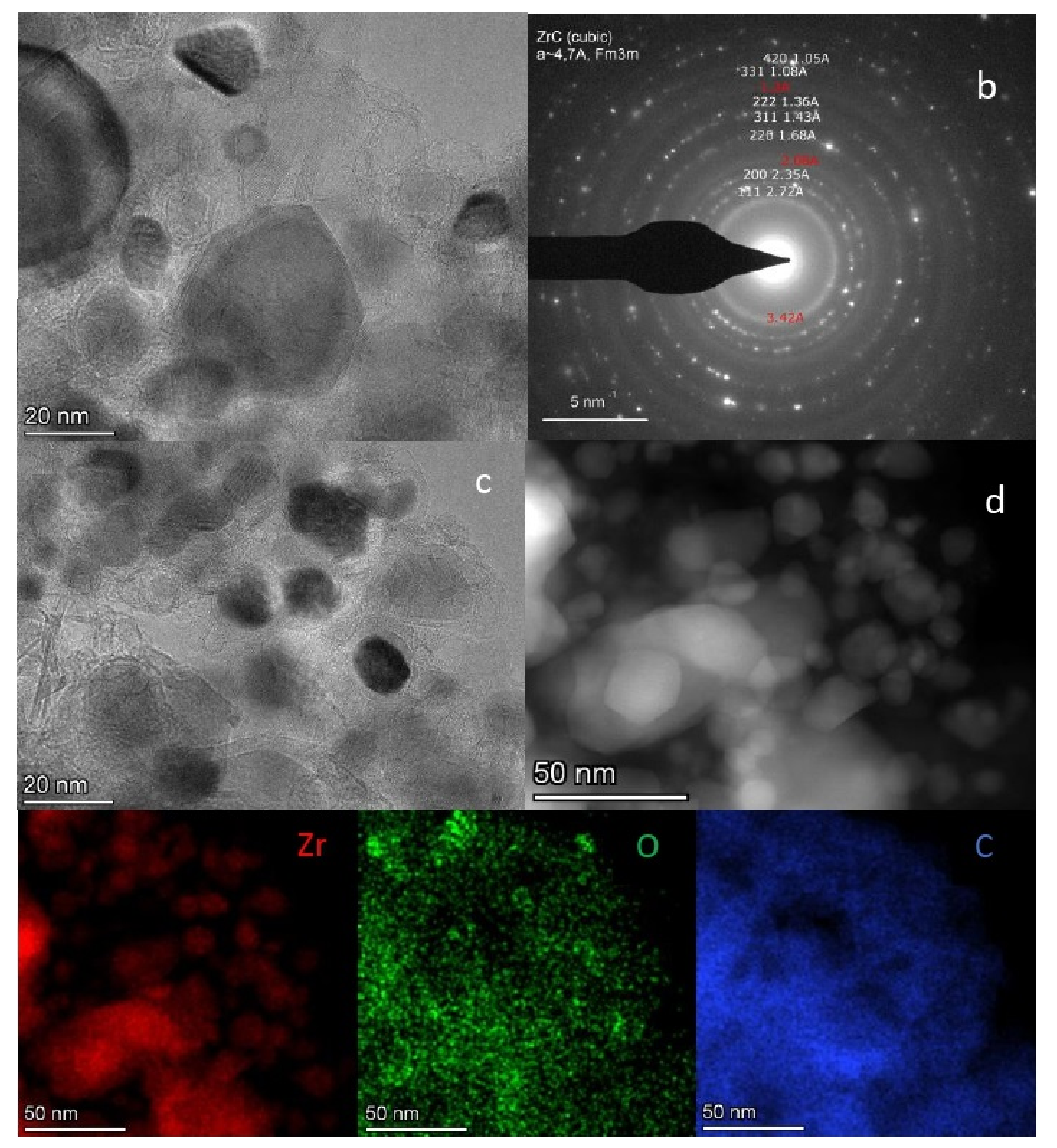
2.6. TEM Analysis of the L-Zr-S-1400-8 and L-Zr-N-1000-P-H2 Samples

We studied HRTEM samples containing ZrC0.58 and ZrC0.94 prepared from the L-Zr-N and L-Zr-S copolymers in RF plasma and tubular furnace. The L-Zr-S-1400-8 sample shows a crystalline ZrO2 monoclinic phase (ESI Figure S14) together with the ZrC cubic phase. (Figure 10).
The HAADF image and elemental maps show the distribution of Zr and O to be very similar. This may be partly attributed to the presence of ZrO2 and partly to the ZrC0.58 phase embedded in a carbon matrix containing a homogeneous oxidized surface. The zirconium-rich ZrC0.58 phase surface may contain some amount of oxygen, as oxycarbide species were detected by XPS as well.
A cubic ZrC0.94 (Fm3m) main phase was identified in L-Zr-N-1000-P-H2 sample by the selected area electron diffraction (SAED) pattern (Figure 11b). Oxygen mainly appears in the smallest particles, which might be attributed to the oxidation of the carbon surface.
The plasma-treated L-Zr-N-1000-P-H2 sample mainly contains ZrC0.94 (Figure 5), which may be attributed to the reaction of zirconium dioxide particles passing through the plasma flame, evaporating, and reacting with carbon. The appropriate residence time for particles in the hottest zone of the plasma varied depending on the particle sizes and the actual thermal trajectory of the individual particles.

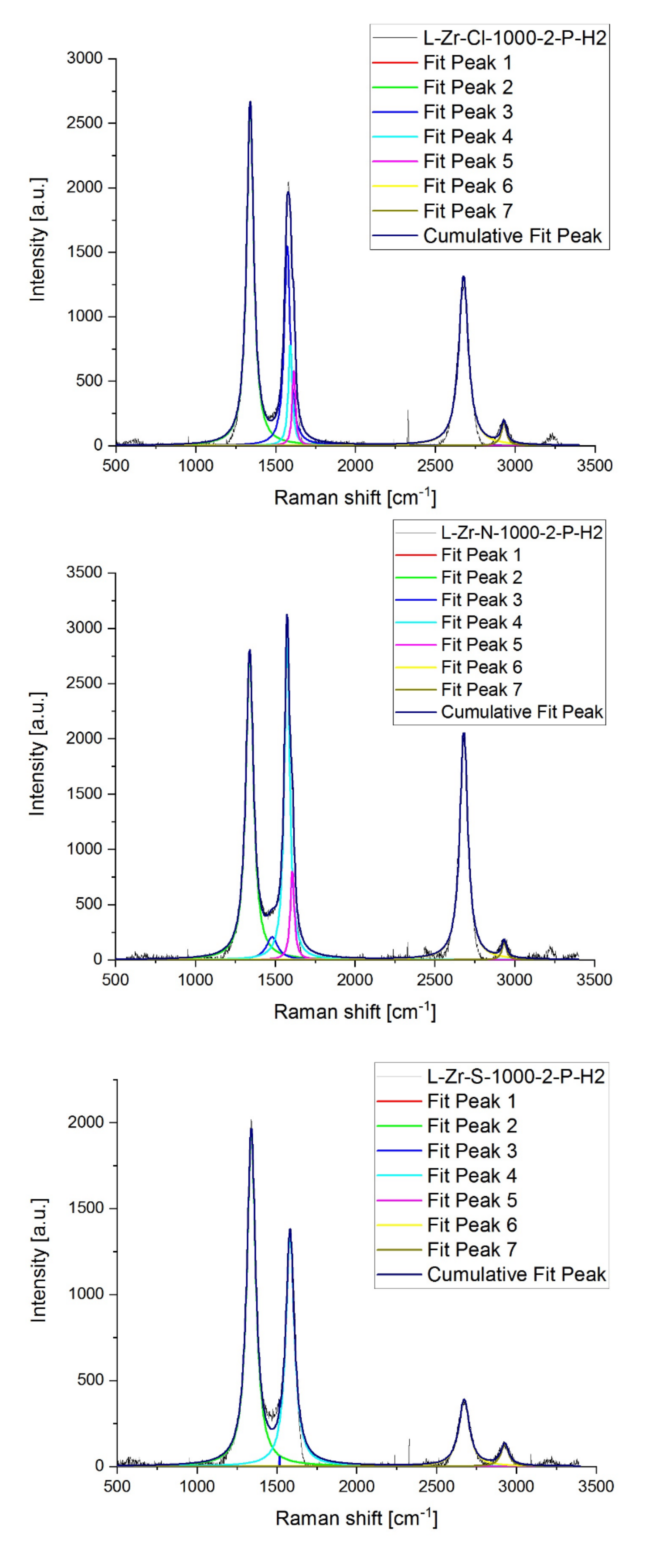
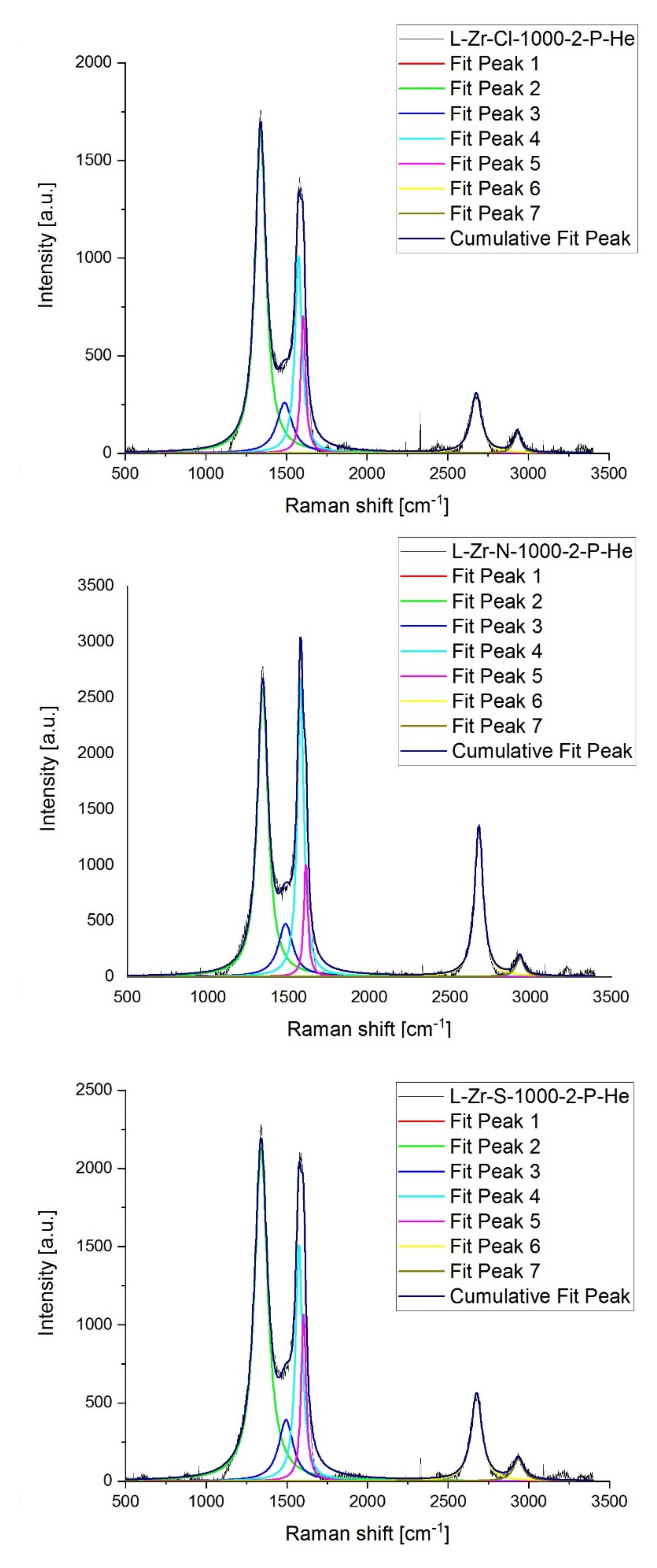
2.7. Raman Studies on ZrO2@C, ZrC@C and (ZrC,ZrO2)@C Composites

Powder XRD analysis is inadequate when exactly determining the ratio of amorphous carbon/graphite components in the nano-(ZrO2, ZrC)@C composites [40]. However, the Raman spectroscopy is suitable for following the quantitative changes in amorphous carbon, graphite and distorted graphite structures and the graphitization processes [27,28,29,30,31,32]. Highly ordered monocrystalline graphite (ideal graphite lattice) has two first-order Raman bands, G (E2g, degenerated optical mode at the center of the Brillouin zone) and G1 (2D) (harmonic in-plane transverse optical mode close to the zone boundary K point) at around 1580 cm−1 and 2687 cm−1, respectively [33,34]. The disordered graphitic lattice has a band D1 (D) (A1g, phonon of the in-plane longitudinal optical branch close to the zone center) and D2 (D’) (E2g, in-plane acoustic branch close to the K point), or graphene layer edges and surfaces, at around 1350 and 1620 cm−1, respectively [37,40,41,42].
The amorphous carbon D3 band (D” or A) is at ca. 1500 cm−1, whereas the D4 (D*) band at ca. 1200 cm−1 contains mixed modes, including a mode of the disordered graphite lattice (A1g), and polyenes or ionic impurities induced modes [27,30,40,41]. Moreover, the Raman spectra of carbonaceous materials contain bands belonging to weak combination (D + D”) and harmonic overtone (2D’) modes as well [42,43,44].
The Raman spectra of composites prepared from L-Zr-X samples between 1000 and 1400 °C for various times for X=Cl, N and S are given in Supplementary Materials, Table S6 and illustrated in Supplementary Materials, Figures S15–S17. The spectra and peak positions/intensities for plasma-treated samples are given in Figure 12 and Figure 13 and Table 4, respectively.
For the L-Zr-Cl-T-t samples, the intensity ratio of the peaks belonging to amorphous/graphitic components (D”/(D+G)) gradually decreases with an increasing reaction temperature, suggesting an advance in graphitization. The D and G bands become sharper due to the formation of more crystalline phases. The intensities of D* and D’ bands decrease with increasing temperature, showing the partial decomposition of organic polyene structures and surface graphene layers, respectively. Increasing the reaction time does not have a considerable effect. The I2D/IG ratio, related to the thickness or separation of the monolayer carbon sheets, slightly and irregularly changes with increasing reaction temperature and time, indicating that Zr atoms are not incorporated into the carbon network to a great extent [45]. The formation of graphite may also be attributed to the increased temperature and the catalytic effect of ZrC [46] forming above 1200 °C. The more ZrC is formed, the more graphite/disordered graphite was detected.
For the samples L-Zr-N-T-t, the catalytic effect of ZrC on graphitization might be more pronounced than the effect of temperature, whereas, for the L-Zr-S-t-t samples, the increase in temperature and reaction time resulted in regular improvements in the graphitization process (Supplementary Materials, Table S6). For the samples made from zirconyl nitrate, the ratio of amorphous carbon to graphite decreases with increasing temperature. The amorphous phase and polyenes completely disappear at 1400 °C in 2 h. Amorphous carbon remains in another experiment conducted at the same temperature but with a longer time (8 h). This shows that there are some differences between the two processes in terms of graphitization. This effect does not directly depend on heating time, but some other unknown factor(s), e.g., activation of some catalytic processes to increase nucleation or crystal growth, might play a role in its appearance.
The Raman spectra of all plasma-treated samples show the complete disappearance of the D* bands due to the thermal decomposition of polyene structures and the transformation of surface graphene layers. The amount of defective graphite and amorphous carbon is the highest in the X=Cl sample made in H2, and when the atmosphere was changed to He, the ID/IG and ID”/(ID+G) ratios decreased from 0.45 to 0.097 and from 3.38 to 1.63, respectively. For the samples with X=N, the ID/IG and ID”/(ID+G) ratios are close to each other. For the samples with X=N, less amorphous carbon is found, and the ratio of defective/regular graphitic structures is almost the same (ID/IG = 0.95 and 0.97 in H2 and He, respectively). A considerable influence of the atmosphere in ABAB stacking and the separation of the monolayer sheets (I2D/IG ratio) was only found for the X=Cl sample [47,48,49].

3. Materials and Methods

Chemical-grade resins and other chemicals (HCl, sulfuric acid, nitric acid, zirconyl nitrate, zirconyl chloride, zirconium(IV) sulfate, sodium hydroxide, calcium oxide and other analytical reagents), were supplied by Deuton-X Ltd., Hungary.

3.1. Experimental

3.1.1. Preparation of L-X-Zr Samples

The iminodiacetate functionalized STY-DVB copolymer containing 2% DVB (Lewatit TP-207, BASF, Lanxess, Germany) was soaked in a 10% aq. acid (HCl, H2SO4 and HNO3) solution for 24 h and the beads that swelled were filled into a 20-cm-long glass column. Activation was conducted using a 10% aq. HCl, H2SO4 and HNO3 solutions, respectively, with a flow rate of 5 mL min−1, and Zr loading was performed using a zirconyl chloride solution containing 0.5 mass% Zr in 3 M HCl until the maximum possible loading with zirconium was reached [5]. Similarly, 0.5 mass% of zirconyl nitrate in 3 M HNO3 and 0.5 M Zr(SO4)2 in 1.5 M H2SO4 were used under the same conditions as ZrOCl2.8H2O.
The L-X-Zr samples that swelled during Zr loading were dried at 90 and 110 °C for 3 h and 2 h, respectively, in ambient air at atmospheric pressure with a heating rate of 10 °C/min. The beads were left to cool in a desiccator filled with freshly prepared CaO.

3.1.2. Carbonization Experiments

The Zr-loaded L-Zr-X resins were subsequently ground in a planetary ball mill (225 rpm, 30 min; Idar-Oberstein, Germany) until their size was reduced to ~63 µm. In each case, ca. 1.6 g of the sample was put into a quartz boat, and the carbonization process (pyrolysis) was performed in a tubular furnace under an Ar atmosphere (alumina tube) at temperatures of 1000, 1200 and 1400 °C for 2 h and 8 h. The heating rate (15 °C min−1) and the volume flow rate of the gas (1.5 L⋅min−1) were kept the same for all the experiments.

3.1.3. RF Plasma Processing

Due to the ~20% swelling water content in the resins (Table S1) and the short residence time of the particles within the RF plasma, the L-Zr-X samples could not be sufficiently directly carbonized. Therefore, we exposed the sample L-Zr-1000-2 prepared with the carbonization of the L-Zr-X samples at 1000 °C for 2 h and containing only ZrO2 and elemental carbon (Table 2). These samples were exposed to in-flight thermal plasma treatment both in an inert (He) and a redutive (H2) atmosphere. The experimental setup is described in [5,28,37]. This consisted of a reactor chamber supplied with a radio-frequency, inductively coupled plasma torch (PL-35, TEKNA Ltd., Sherbrooke, Canada, mounted on the top) and an RF generator (LEPEL, Waukesha, USA) with a maximum power of 30 kW at 4–5 MHz, together with a cyclone, a filter unit and a vacuum pump [5]. The solid samples were delivered into the plasma as described in [5] via a Praxair feeder (Danbury, Connecticut, USA) with He as carrier gas (flow rate of 5 L⋅min−1). The feeding probe was coaxially in the middle of the induction coil. The feeding rate of the powdered resins was 3 g⋅min−1. The plasma gas was a mixture of 11 L⋅min−1 Ar and 6 L⋅min−1 He, whereas the sheath gas was a mixture of 35 L⋅min−1 Ar and 5 L⋅min−1 He. The same experiments were performed with hydrogen in sheath gas instead of He with a flow rate of 5 L⋅min−1. The most important operating conditions for the particular tests were adapted from [5] (70 kPa and 25 kW of power).

3.1.4. Elemental Analysis

The CHS analysis of the L-Zr-X samples were carried out after drying them in glass vials in a vacuum oven (Thermo Electron, Karlsruhe, Germany) at 140 °C for 19 h (tightly capped under N2 and sealed with a plastic film) was performed with a Carlo Elba 1106 instrument.

3.1.5. Specific Surface Area Measurements

We calculated the surface area using the Brunauer–Emmett–Teller (BET) equation from nitrogen adsorption data collected at −196 °C (Autosorb 1C, Quantachrome, Boynton Beach, Florida, USA). The samples were evacuated for 24 h at 100 °C prior to measurements.

3.1.6. Transmission Electron Microscopy

Transmission Electron Microscopy (TEM) was carried out with a 200 keV (Talos Thermo Scientific, Santa Clara, CA, USA) transmission electron microscope. Grains were crushed in EtOH and deposited onto Cu grids covered by Lacey carbon. We obtained bright-field TEM (BFTEM), high-resolution TEM (HRTEM), and high-angle annular dark-field (HAADF) scanning TEM images as well as selected-area electron diffraction (SAED) patterns. In TEM mode, the current was ~600 pA and the SAED patterns were obtained with a camera length of 520 mm [5]. In addition, we performed elemental mapping in STEM mode to study the grains’ chemical composition and heterogeneity. In STEM mode, the current was ~200 pA. Beam convergence was 10.5 mrad. The camera length was 125 mm. Dwell time was 10 µs. We used a “Super-X” detector system with 4 silicon drift detectors built into the microscope column. Fast Fourier transforms (FFTs) were calculated from the HRTEM images with the Digital Micrograph 3.6.1 software (Gatan Inc., Pleasanton, CA, USA). The details of TEM spectroscopy are given in [32].

3.1.7. Thermal Studies

We performed simultaneous thermogravimetric analysis (TGA), differential scanning calorimetry (DSC) and mass spectrometric evolved gas analysis (MS-EGA) using a SETARAM Labsys Evo and a Pfeiffer Vacuum OmniStar instrument, under a high-purity He gas stream (6.0) with a heating rate of 10 °C/min from 25 °C to 1600 °C. The details of thermal measurements are given in [31,32]

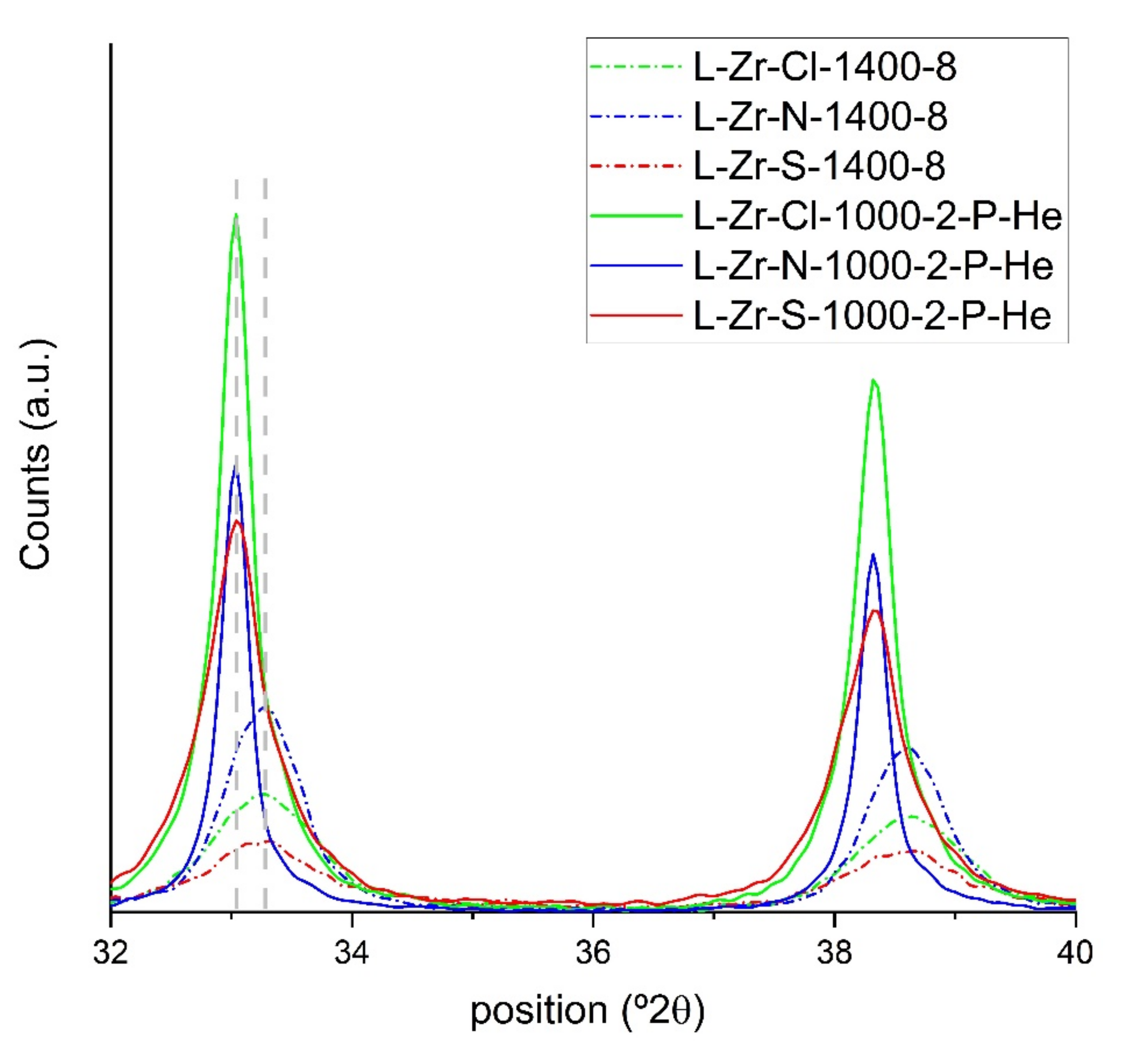
3.1.8. Powder X-ray Diffraction

A Philips Bragg–Brentano parafocusing goniometer was used to acquire powder XRD patterns (Cu weighted Kα radiation, 1.5406/1.5444 Å) in the range of 4–70° 2θ (with a step size of 0.02° and an interval time of 1 s). Although the unit cell dimensions of the phases were well-determined, the composition (in mass%) of phases should be considered an estimate rather than an accurate value. Due to the amorphous carbon content, problems occurred when determining the background. Thus, no goodness-of-fit parameters are given. The details of the XRD measurements are given in [32].

3.1.9. Vibrational Spectroscopy

The analytical IR and far-IR range spectra were collected on a Bruker Alpha FT-IR (Bruker, Ettingen, Germany) and a Biorad-Digilab FTS-30-FIR far-IR instrument (Hercules, CA, USA) with a Smart Attenuated Total Reflectance (ATR) accessory, respectively. All spectra were recorded from 16 scans and acquired with a resolution of 4 cm−1 [33,34,35].
A Horiba Jobin–Yvon LabRAM micro-spectrometer (Longjumeau, France) was used, with an external Nd-YAG laser source of 532 nm for Raman spectroscopy. We focused the laser beam on an objective (20X, numerical aperture = 0.4) using a D0.3 or D0.6 optical filter, which reduced the intensity of the laser to avoid degradation. A total of 1000 µm of the confocal hole was used, with a grating monochromator of 1800 mm−1 for light dispersion. The wavenumbers were scanned with a resolution of 3 cm−1, with an accumulation time of 90–120 s per point for all the spectra in a range of 200–3400 cm−1. After baseline correction, the first- and second-order regions of the spectra were deconvoluted into Lorentzian functions using the fitting tool available in the Origin software.

3.1.10. X-ray Photoelectron Spectroscopy

The X-ray photoelectron spectra (XPS) of the RF plasma-treated samples were recorded with a Kratos XSAM 800 instrument (Manchester, UK) in fixed analyzer transmission mode, with a pass energy of 40 eV, Mg Kα1,2 (1253.6 eV) excitation and an analysis chamber pressure of < 1·10−7 Pa. Survey spectra were recorded for both samples in the 100–1300 eV kinetic energy range. High-resolution spectra of the characteristic photoelectron lines of zirconium, oxygen, and carbon were recorded with 0.1 eV steps and a dwell time of 1 s. Quantitative analysis (after removal of the Shirley background) was performed with the XPS MultiQuant program (Version 7.8, M. Mohai, Budapest, Hungary) with experimentally determined photoionization cross-section data and asymmetry parameters [39].

3.1.11. Solid-State NMR Measurements

15N NMR magic angle spinning (MAS) spectra were recorded on a Varian System spectrometer operating at a 1H frequency of 600 MHz with a Chemagnetics 6.0-mm narrow-bore triple resonance T3 probe in double resonance mode. 15N cross-polarization spectra were recorded with 5 ms contact time at 18 °C with a spinning rate of 1.6 kHz. 13C magic angle spinning (MAS) spectra were recorded on a Varian System spectrometer operating at a 1H frequency of 400 MHz with a Chemagnetics 4.0 mm narrow-bore double resonance T3 probe. 13C cross-polarization spectra were recorded with 2 ms contact time at 18 °C with a spinning rate of 8.0 kHz. A repetition delay of 20 s and TPPM decoupling were used in all the measurements. For the 15N and 13C measurements, glycine and adamantane were used as a chemical shift reference.

4. Conclusions

(1)
Due to the low (2%) divinylbenzene content of the Zr-loaded iminodiacetate functional groups containing styrene-divinylbenzene (L-Zr-X) copolymers samples, a significant loss of the organic volatiles was observed during the carbonization reaction of the L-Zr-X samples, which resulted in high ZrO2/C and ZrC/C ratios in the precursor and product samples, respectively.
(2)
Changing the anion in the zirconium salt used to load the chelate-forming resin resulted in ZrO2@C precursors with varying reactivity levels towards carbonization and alterable Zr content.
(3)
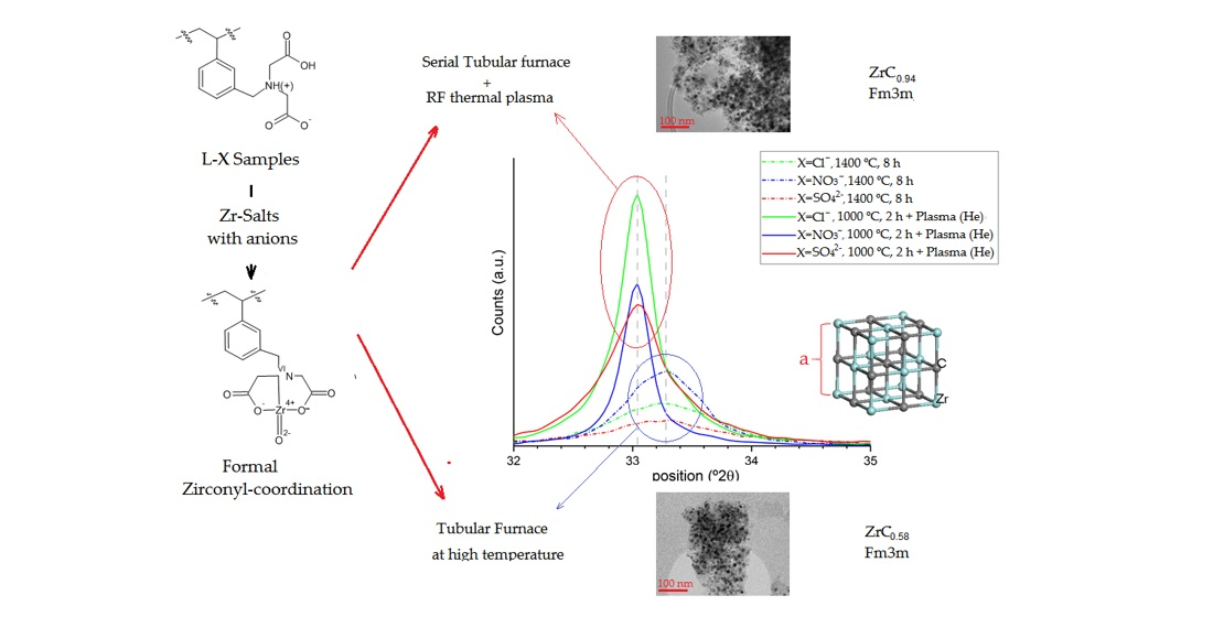
ZrC0.54@C samples can be prepared with or without ZrO2 in a tubular furnace, with nanosize ZrC and ZrO2 content.
(4)
The RF plasma treatment of ZrO2@C samples led to ZrC0.94@C samples with high (75–95%) nanosized ZrC0.94 content and a pore volume of 0.20–0.26 cm3/g, with or without graphite content.

Supplementary Materials

The following supporting information can be downloaded at: https://www.mdpi.com/article/10.3390/inorganics10060077/s1. ESI Scheme S1. Synthesis of the sodium salt of iminodiacetate functionalized STY-DVB copolymers. ESI Table S1. Elementary analyses result on L-Zr-X Zr-loaded iminodiacetate-functionalized styrene-divinylbenzene copolymers. ESI Table S2. Surface composition of composites prepared by heat treatment of L-Zr-Cl resins at 1000 and 1200 °C for 2 h, or at 1400 °C for 2 and 4 h. ESI Table S3. Surface composition of composites prepared by heat treatment of L-Zr-N resins at 1000 and 1200 °C for 2 h, or at 1400 °C for 2 and 4 h. ESI Table S4. Surface composition of composites prepared by heat treatment of L-Zr-S resins at 1000 and 1200 °C for 2 h, or at 1400 °C for 2 and 4 h. ESI Table S5. Surface composition of composites prepared by RF plasma treatment of L-Zr-X-1000-2 resins in H2 and He atmosphere. ESI Table S6. Raman band positions (cm−1 ) and band intensities (arbitrary units) in the Raman spectra of L-Zr-X-T-t composites. ESI Figure S1. IR spectrum of the iminodiacetate functionalized STY-DVB copolymer. ESI Figure S2. IR patterns for L-Zr-X samples for X= S, Cl and N between the intervals 4000–3000 cm-1 and 2000–400 cm−1. ESI Figure S3. IR spectra of iminodiacetic acid (IDA) salts with H2SO4(IDA-S), HNO3 (IDA-N), and HCl (IDA-Cl) between the intervals 4000–3000 cm−1 and 2000–400 cm−1. ESI Figure S4. IR spectra of L-S and L-Zr-S compounds between 2000 and 400 cm−1. ESI Figure S5. IR spectra of L-N and L-Zr-N compounds between 2000 and 400 cm−1. ESI Figure S6. IR spectra of L-Cl and L-Zr-Cl compounds between 2000 and 400 cm−1. ESI Figure S7. 13C CP MAS solid state NMR spectra of L-X and L—Zr-X samples (X=Cl (Top), N(Middle) and S(Botton)). ESI Figure S8. TG-MS curves of iminodiacetate groups (a) and STY-DVB skeleton fragments (b,c) in the decomposition of L-Zr-N sample. ESI Figure S9. TG-MS curves of iminodiacetate groups (a) and STY-DVB skeleton fragments (b,c) in the decomposition of L-Zr-S sample. ESI Figure S10. TG-DSC curves of the decomposition of L-Zr-X sample (X=Cl (green), N (Blue), S (Red)). ESI Figure S11. Complete XRD pattern of L-Zr-X-1400-8 and L-Zr-X-1000-2-P-He (X=Cl, N and S) samples. ESI Figure S12. X-ray photoelectron spectra of the O1s lines of the nano-ZrO2@C and nano-(Zr0.58C,ZrO2)@C containing composites. ESI Figure S13. X-ray photoelectron spectra of the O1s lines of the RF-plasma treated nano Zr0.94C@C containing composites. ESI Figure S14. Identification of crystalline monoclinic ZrO2 in The L-Zr-S-1400-8 sample. ESI Figure S15. Raman spectra of L-Zr-Cl-T-t samples. ESI Figure S16. Raman spectra of L-Zr-N-T-t samples. ESI Figure S17. Raman spectra of L-Zr-S-T-t samples.

Author Contributions

Conceptualization, A.M. (Alejandro Martiz), Z.K. and L.K.; methodology, Z.K., L.K.; software, A.M. (Alejandro Martiz); formal analysis, M.M.; investigation, A.M. (Alejandro Martiz), Z.K., A.D., L.B., L.T., A.F., K.L.; resources, Z.K., A.M. (Alejandro Martiz), data curation, A.M. (Alejandro Martiz), Z.K. and L.K.; writing—original draft preparation, A.M. (Alejandro Martiz), Z.K. and L.K.; writing—review and editing, A.M. (Alejandro Martiz), Z.K. and L.K.; visualization, A.M. (Alejandro Martiz), L.B., A.F.; supervision, L.K.; project administration, A.M. (Alfréd Menyhárd); funding acquisition, Z.K. All authors have read and agreed to the published version of the manuscript.

Funding

Alejandro Martiz thanks to Tempus Public Foundation for the financial support granted through the Stipendium Hungaricum scholarship program.

Institutional Review Board Statement

Not applicable.

Informed Consent Statement

Not applicable.

Data Availability Statement

Not applicable.

Acknowledgments

TEM studies were performed at the electron microscopy laboratory of the University of Pannonia, established using grant no. GINOP-2.3.3-15-2016-0009 from the European Structural and Investments Funds and the Hungarian Government.

Conflicts of Interest

The authors declare no conflict of interest.

References

  1. Pierson, H.O. Handbook of Refractory Carbides and Nitrides: Properties, Characteristics, Processing and Applications, 1st ed.; Noyes Publication: Westwood, NJ, USA, 1997. [Google Scholar]
  2. Liu, G.; Cheng, L.; Li, K.; Chen, Z.; Xiong, X.; Luan, X. Damage behavior of atomic oxygen on zirconium carbide coating modified carbon/carbon composite. Ceram. Int. 2020, 3, 3324–3331. [Google Scholar] [CrossRef]
  3. Scales, N.; Chen, J.; Aughterson, R.D.; Karatchevtseva, I.; Stopic, A.; Lumpkin, G.R.; Luca, V. Porous ZrC-carbon microspheres as potential insoluble target matrices for production of 188W/188Re. J. Radioanal. Nucl. Chem. 2018, 318, 835–847. [Google Scholar] [CrossRef]
  4. Scales, N.; Chen, J.; Hanley, T.L.; Riley, D.P.; Lumpkin, G.R.; Luca, V. Hierarchically porous carbon–zirconium carbide spheres as potentially reusable transmutation targets. Microporous Mesoporous Mater. 2015, 212, 100–109. [Google Scholar] [CrossRef]
  5. Martiz, A.; Károly, Z.; Bódis, E.; Fazekas, P.; Mohai, M.; Bertóti, I.; Keszler, A.M. In-flight Synthesis of Nanosized ZrC Particles from Various Precursors in RF-Thermal Plasma. Period. Polytech.-Chem. 2021, 65, 331–342. [Google Scholar] [CrossRef]
  6. Cheng, W.; Campolongo, M.J.; Tan, S.J.; Luo, D. Freestanding ultrathin nano-membranes via self-assembly. Nano Today. 2009, 4, 482–493. [Google Scholar] [CrossRef]
  7. Byrappa, K.; Ohara, S.; Adschiri, T. Nanoparticles synthesis using supercritical fluid technology towards biomedical applications. Adv. Drug Deliv. Rev. 2008, 60, 32714. [Google Scholar] [CrossRef]
  8. Hussain, I.; Jalil, A.A.; Hamid, M.Y.S.; Hassan, N.S. Recent advances in catalytic systems in the prism of physicochemical properties to remediate toxic CO pollutants: A state-of-the-art review. Chemosphere 2021, 277, 130285. [Google Scholar] [CrossRef]
  9. Kocsis, T.; May, Z.; Czégény, Z.; Sreedhar, B.; Pawar, R.P.; Kótai, L. Perspectives of magnetic and nanosized metal-containing amorphous carbon composite chemosorbents and catalysts. Nano Stud. 2016, 14, 7–35. [Google Scholar]
  10. Dou, B.; Wang, C.; Song, Y.; Chen, H.; Jiang, B.; Yang, M.; Xu, Y. Solid sorbents for in-situ CO2 removal during sorption-enhanced steam reforming process: A review. Renew. Sust. Energy Rev. 2016, 53, 536–546. [Google Scholar] [CrossRef]
  11. Ciddor, L.; Bennett, J.A.; Hunns, J.A.; Wilson, K.; Lee, A.F. Catalytic upgrading of bio-oils by esterification. J. Chem. Technol. Biotechnol. 2015, 90, 780–795. [Google Scholar] [CrossRef] [Green Version]
  12. Wang, C.; Cheng, R.; Liao, L.; Duan, X. High-performance thin-film electronics based on inorganic nanostructures and composites. Nano Today 2013, 8, 514–530. [Google Scholar] [CrossRef]
  13. Basumatary, S. Transesterification with heterogeneous catalyst in production of biodiesel: A review. J. Chem. Pharm. 2013, 5, 1–7. [Google Scholar]
  14. Fedorov, P.P.; Yarotskaya, E.G. Zirconium dioxide. Review. Kondens. Sredy Mezhfaznye Granitsy Condens. Matter Interphases 2021, 23, 169–187. [Google Scholar] [CrossRef]
  15. Dunlap, C.J.; Mcneff, C.V.; Stoll, D.; Carr, P.W. Zirconia stationary phases for extreme separations. Anal. Chem. 2001, 73, 599A–607A. [Google Scholar] [CrossRef] [PubMed] [Green Version]
  16. Camps, M.; Chatzopoulos, M.; Camps, J.M.; Montheards, J.P. Chloromethylation of Polystyrenes and Styrene Copolymers. Applications. JMS-Rev. Macromol. Chem. Phys. 1987, 27, 505–557. [Google Scholar]
  17. Yuchi, A.; Yoshida, N. Adsorption of tetravalent metal ions chelating resins containing iminodiacetic acid groups. Bull. Chem. Soc. Jpn. 2000, 73, 1841–1842. [Google Scholar] [CrossRef]
  18. Auer, B.M.; Skinner, J.L. IR and Raman spectra of liquid water: Theory and interpretation. J. Chem. Phys. 2008, 128, 224511. [Google Scholar] [CrossRef]
  19. Ikawa, K.; Iwamoto, K. Coating microspheres with zirconium carbide-carbon alloy. J. Nucl. Mater. 1974, 52, 128–130. [Google Scholar] [CrossRef]
  20. Ikawa, K. Vapor deposition of zirconium carbide-carbon composites by the chloride process. JCOMA 1972, 29, 233–239. [Google Scholar] [CrossRef]
  21. González Vílchez, M.C.; Puerta Vizcaíno, M.F.; Gargallo, E. Thermal behavior of iminodiacetic acid and its disodium salt. Thermochim. Acta 1980, 42, 295–303. [Google Scholar] [CrossRef]
  22. Li, F.; Huang, X.; Zhang, G.J. Scalable foaming assisted synthesis of ZrC nanopowder by carbothermal reduction. Ceram Int. 2015, 41, 3335–3338. [Google Scholar] [CrossRef]
  23. Sacks, M.D.; Wang, C.A.; Yang, Z.; Jain, A. Carbothermal reduction synthesis of nanocrystalline zirconium carbide and hafnium carbide powders using solution-derived precursors. J. Mat. Sci. 2004, 39, 6057–6066. [Google Scholar] [CrossRef]
  24. Byun, H.S.; Burford, R.P.; Fane, A.G. Sulfonation of crosslinked asymmetric membranes based on polystyrene and divinylbenzene. J Appl. Polym. Sci. 1994, 52, 825–835. [Google Scholar] [CrossRef]
  25. Dobson, K.D.; McQuillan, A.J. An Infrared Spectroscopic Study of Carbonate Adsorption to Zirconium Dioxide Sol-Gel Films from Aqueous Solutions. Langmuir 1997, 13, 3392–3396. [Google Scholar] [CrossRef]
  26. Jiang, J.; May, I.; Sarsfield, M.J.; Ogden, M.; Fox, D.O.; Jones, C.J.; Mayhew, P. Spectroscopic Study of the Dissolution of Cesium Phosphomolybdate and Zirconium Molybdate by Ammonium Carbamate. J. Sol. Chem. 2005, 34, 443–468. [Google Scholar] [CrossRef]
  27. Fitzgerald, J.J.; Weiss, R.A. Cation-Anion and Cation-Cation Interactions in Sulfonated Polystyrene Ionomers Spectroscopic Studies of the Effects of Solvents. ACS 1986, 302, 35–53. [Google Scholar]
  28. El-NahhalI, I.M.; Zaggout, F.R.; Nassar, M.A.; El-Ashgar, N.M.; Maquet, J.; Babonneau, F.; Chehimi, M. Synthesis, Characterization and Applications of Immobilized Iminodiacetic Acid-Modified Silica. J Sol-Gel Sci. Technol. 2003, 28, 255–265. [Google Scholar] [CrossRef]
  29. Jiang, J.; Renshaw, J.C.; Sarsfield, M.J.; Livens, F.R.; Collison, D.; Charnock, J.M.; Eccles, H. Solution Chemistry of Uranyl Ion with Iminodiacetate and Oxydiacetate: A Combined NMR/EXAFS and Potentiometry/Calorimetry Study. Inorg. Chem. 2003, 42, 1233–1240. [Google Scholar] [CrossRef]
  30. Busca, G.; Lorenzelli, V. Infrared spectroscopic identification of species arising from reactive adsorption of carbon oxides on metal oxide surfaces. Mater. Chem. 1982, 7, 89–126. [Google Scholar] [CrossRef]
  31. Kawashiro, K.; Morimoto, S.; Yoshida, H. Mass spectra of butyl esters and N-trifluoroacetyl butyl esters of some iminodicarboxylic acids upon electron impact. Bull. Chem. Soc. Jpn. 1984, 57, 1097–1103. [Google Scholar] [CrossRef] [Green Version]
  32. Fazekas, P.; Czégény, Z.; Mink, J.; Bódis, E.; Klébert, S.; Németh, C.; Keszler, A.M.; Károly, Z.; Szépvölgyi, J. Decomposition of poly(vinyl chloride) in inductively coupled radiofrequency thermal plasma. Chem. Eng. J. 2016, 302, 163–171. [Google Scholar] [CrossRef] [Green Version]
  33. Komarov, V.S.; Yatsevskaya, M.I.; Sycheva, O.A. Properties of activated carbon produced from spent ion-exchange resins. Dokl. Akad. Nauk. BSSR 1985, 29, 1010–1023. [Google Scholar]
  34. Chinthaka Silva, G.W.; Kercher, A.A.; Hunn, J.D.; Martin, R.C.; Jellison, G.E.; Meyer, H.M. Characterization of zirconium carbides using electron microscopy; optical anisotropy; Auger depth profiles, X-ray diffraction and electron density calculated by charge flipping method. J. Solid State Chem. 2012, 194, 91–99. [Google Scholar] [CrossRef]
  35. Gusev, A.I. Structural stability boundaries for nonstoichiometric compounds. Phys. Status Solidi A 1989, 111, 443–450. [Google Scholar] [CrossRef]
  36. Senczyk, D. The lattice parameters of MeC-type carbides; nitrides and carbonitrides of transition metals of IV and V groups of the periodic system. In Proceedings of the 11th Conference of Applied Crystallography, Kozubnik, Poland; 1984; Volume 1, pp. 234–240. [Google Scholar]
  37. Martiz, A.; Károly, Z.; Trif, L.; Mohai, M.; Bereczki, L.; Németh, P.; Molnár, Z.; Menyhárd, A.; Pawar, R.P.; Tekale, S.; et al. Plasma-assisted preparation of nano-(ZrC; ZrO2)@carbon composites from Zr-loaded sulfonated styrene–divinylbenzene copolymers. J. Therm. Anal. Calorim. 2022, 1–13, in press. [Google Scholar] [CrossRef]
  38. Pechishcheva, N.V.; Shunyaev, K.Y.; Melchakova, O.V. Zirconium in modern analytical chemistry. Rev. Anal. Chem. 2018, 37, 1–26. [Google Scholar] [CrossRef]
  39. Reilman, R.F.; Msezane, A.; Manson, S.T. Relative intensities in photoelectron spectroscopy of atoms and molecules. J. Electron. Spectr. Relat. Phenom. 1976, 8, 389–394. [Google Scholar] [CrossRef]
  40. Martiz, A.; Farkas, A.; Karoly, Z.; Franguelli, F.P.; Samaniego, S.K.; Menyhard, A.; Kotai, L. Raman studies on carbon-containing phases in nanosized-ZrO2/C and nanosized-(ZrC; ZrO2)/C composites. Nano Stud. 2022, 10, 21–22. [Google Scholar]
  41. Devia, D.H.; Sykes, A.G. Aqueous solution chemistry of zirconium(IV). 1. Kinetic studies on hydrogen ion and general acid (HX) induced dissociations of the tetrameric ion [Zr4(OH)8(H2O)16]8+. Inorg. Chem. 1981, 20, 910–913. [Google Scholar] [CrossRef]
  42. Lokshin, E.P.; Tareeva, O.A. Sorption of Zirconium from Nitrate and Sulfate Solutions. Theor. Found. Chem. Eng. 2019, 53, 688–692. [Google Scholar] [CrossRef]
  43. Clearfield, A. Structural aspects of zirconium chemistry. Rev. Pure Appl. Chem. 1964, 14, 91–108. [Google Scholar]
  44. Fathy, M.; Moghny, T.A.; Awadallah, A.E.; El-Bellihi, A.H. Nano Composites of Polystyrene Divinyl Benzene Resin Based on Oxidized Multi-Walled Carbon Nanotubes. Int. J. Mod. Org. Chem. 2013, 2, 67–80. [Google Scholar]
  45. Shishlov, N.M.; Khurasan, S.L. Effect of ion interactions on the IR spectrum of benzenesulfonate ion. Restoration of sulfonate ion symmetry in sodium benzenesulfonate dimer. J. Mol. Struct. 2016, 1123, 360–366. [Google Scholar]
  46. De, R.; Lee, H.; Das, B. Exploring the interactions in binary mixtures of polyelectrolytes: Influence of mixture composition; concentration; and temperature on counter-ion condensation. J. Mol. Liq. 2018, 251, 94–99. [Google Scholar] [CrossRef]
  47. Claramunt, S.; Varea, A.; Lopez-Diaz, D.; Velazquez, M.; Cornet, A.; Cirera, A. The Importance of Interbands on the Interpretation of the Raman Spectrum of Graphene Oxide. J. Phys. Chem. C 2015, 119, 10123–10129. [Google Scholar] [CrossRef]
  48. Vollebregt, S.; Ishihara, R.; Tichelaar, F.D.; Hou, Y.; Beenakker, C.I.M. Influence of the growth temperature on the first and secondorder Raman band ratios and widths of carbon nanotubes and fibers. Carbon 2012, 50, 3542–3554. [Google Scholar] [CrossRef]
  49. Cuesta, A.; Dhamelincourt, P.; Laureyns, J. Raman Microprobe studies on carbon materials. Carbon 1994, 8, 1523–1532. [Google Scholar] [CrossRef]
Scheme 1. (a) Synthesis route of Zr-loaded iminodiacetate functionalized STY-DVB copolymers; (b) the structure of chelating (a), neutralizing (a) and surplus (b) iminodiacetate groups in the L-Zr-X complexes.
Inorganics 10 00077 sch001
Figure 1. IR spectra of IDA-S, L-S and L-Zr-S samples.
Inorganics 10 00077 g001
Figure 2. 15N CP MAS solid-state NMR spectra of L-NO3 (a) and L-Zr-NO3 (b) samples.
Inorganics 10 00077 g002
Figure 3. TG-MS curves for H2O and CO2 evolution during decomposition of L-Zr-X samples.
Inorganics 10 00077 g003
Figure 4. TG-MS decomposition curves of iminodiacetate group (a) and STY-DVB skeleton fragments, depolymerization products (b), and aromatics (c) of L-Zr-Cl sample.
Inorganics 10 00077 g004
Figure 5. XRD pattern of L-Zr-X-1400-8 and L-Zr-X-1000-2-P-He (X=Cl, N and S) samples.
Inorganics 10 00077 g005
Figure 6. X-ray photoelectron spectra of the Zr3d lines of the composites containing nano-ZrO2@C and nano-(Zr0.58C,ZrO2)@C.
Inorganics 10 00077 g006
Figure 7. X-ray photoelectron spectra of the C1s lines of the composites containing nano-ZrO2@C and nano-(Zr0.58C,ZrO2)@C.
Inorganics 10 00077 g007
Figure 8. X-ray photoelectron spectra of the Zr3d lines of the composites containing zirconium carbide prepared in RF plasma at various conditions.
Inorganics 10 00077 g008
Figure 9. X-ray photoelectron spectra of the C1s lines of the composites containing zirconium-carbide prepared in RF plasma.
Inorganics 10 00077 g009
Figure 10. Images (a,c), SAED pattern identifying the presence of cubic ZrC (b) and HAADF image (d) of L-Zr S-1400-8 sample, together with the elemental distribution maps for zirconium (yellow), oxygen (red) and carbon (blue).
Inorganics 10 00077 g010
Figure 11. Images (a,c), SAED pattern identifying the presence of cubic ZrC (b) and HAADF image (d) of L-Zr-N-1000-P-H2 sample, together with the elemental distribution maps for zirconium (red), oxygen (green) and carbon (blue).
Inorganics 10 00077 g011
Figure 12. Raman spectra of plasma-treated L-Zr-X-P-H2 samples (X=Cl, N and S).
Inorganics 10 00077 g012
Figure 13. Raman spectra of plasma-treated L-Zr-X-P-He samples (X=Cl, N and S).
Inorganics 10 00077 g013
Table 1. Labels for samples.
LabelDescription of Sample
L-XH-form of iminodiacetate-functionalized STY-DVB copolymers containing 2 mass% DVB.
L-X-ZrZirconium-loaded iminodiacetate-functionalized STY-DVB copolymer samples containing 2 mass% DVB with ZrOX2 (X=Cl NO3) and Zr(SO4)2 (X=S) salts.
L-X-Zr-T-tSamples obtained by carbonizing L-X-Zr resins at the given T temperature and for a carbonization time of t.
L-Zr-X-1000-2-P-H2/HePlasma-treated samples from L-Zr-X-1000-2 samples containing ZrO2@C in a H2 or He atmosphere.
Table 2. Composition and properties of (ZrC0.58, ZrO2)@C composites prepared from L-Zr-Cl, L-Zr-N and L-Zr-S resins in a tubular furnace.
CompositeZrC,
(wt%)
(Size in nm)
ZrO2
(wt%)
(Size in nm)
Carbon
(wt%)
BET Surface Area
(m2/g)
L-Zr-Cl-1000-2-65 (5)
Ortho/tetra = 1.36
35140
L-Zr-Cl-1200-275 (10)15 (11) tetra10311
L-Zr-Cl-1400-280 (10)10 (12) tetra10310
L-Zr-Cl-1400-885 (14)5 (26) tetra/mono = 1.9210245
L-Zr-N-1000-2-80(5)
ortho/tetra = 0.77
20278
L-Zr-N-1200-265 (10)25 (7) tetra10447
L-Zr-N-1400-295 (17)-5430
L-Zr-N-1400-895 (18)-5438
L-Zr-S-1000-2-10 (8)9033
L-Zr-S-1200-250 (8)10 (8)
ortho/tetra = 0.26
4041
L-Zr-S-1400-230(13)15 (8) tetra5554
L-Zr-S-1400-850 (56)5 (31)
mono/cubic = 1.05
5535
Table 3. Composition and properties of ZrC0.94@C composites prepared in RF plasma.
SampleZrC,
(wt%)
(Size in nm)
Carbon (wt%)BET Surface Area
(m2/g)
Total Pore Volume (cm3/g)
L-Cl-1000-2-P-He95 (49)5500.21
L-Cl-1000-2-P-H290 (40)10620.26
L-N-1000-2-P-He95 (62)5520.22
L-N-1000-2-P-H290 (35)15820.22
L-S-1000-2-P-He80 (40)20520.20
L-S-1000-2-P-H275 (42)20580.22
Table 4. Raman shifts peak positions (in cm−1) and their intensities (in arbitrary units) for the plasma-treated samples.
Sample D *DD”GD’2DD + D’ID/IGI2D/IG
L-Zr-Cl-1000-2-P-H2R shift
[cm−1]
1100134015721592161426762929
Intensity02650155278458513131733.381.68
FWHM053.5344.3829.4023.4771.7240.98
L-Zr-Cl-1000-2-P-HeR shift
[cm−1]
1100133914881574160326752930
Intensity0164725910127053051101.630.30
FWHM081.88115.552.1735.5979.0454.11
L-Zr-N-1000-2-P-H2R shift
[cm−1]
1100134014801574160626802933
Intensity02762206290780220701570.950.71
FWHM057.9288.5440.5129.7360.0635.56
L-Zr-N-1000-2-P-HeR shift
[cm−1]
1100133914811574160726792933
Intensity025814752670100413431780.970.50
FWHM080.57109.446.9430.0062.4757.14
L-Zr-S-1000-2-P-H2R shift
[cm−1]
1100133915171582207826712925
Intensity0194360.55134903871271.440.29
FWHM065.450.11364.27079,959.33
L-Zr-S-1000-2-P-HeR shift
[cm−1]
1100134014941575160426762934
Intensity02128392151110685581431.410.37
FWHM097.33109.551.3635.9780.1375.83
Publisher’s Note: MDPI stays neutral with regard to jurisdictional claims in published maps and institutional affiliations.

