Article

Three-Dimensional Force Sensor Based on Fiber Bragg Grating for Medical Puncture Robot

1
School of Communication and Information Engineering, Chongqing University of Posts and Telecommunications, Chongqing 400065, China
2
Foundation Department, Chongqing Medical and Pharmaceutical College, Chongqing 401331, China
3
School of Bioinformatics, Chongqing University of Posts and Telecommunications, Chongqing 400065, China
*
Author to whom correspondence should be addressed.
Photonics 2022, 9(9), 630; https://doi.org/10.3390/photonics9090630
Submission received: 9 August 2022 / Revised: 30 August 2022 / Accepted: 31 August 2022 / Published: 2 September 2022
(This article belongs to the Section Lasers, Light Sources and Sensors)

Abstract

:
In medical puncture robots, visible light, infrared and ultrasound images are currently used to guide punctures. The lack of information about the interaction forces between the puncture needle and soft tissue in different directions during the puncture process can easily lead to soft tissue being damaged. The current three-dimensional force sensors are large and can only be mounted on the base of the puncture needle, which does not allow for easy integration. Moreover, the force transfer to the base introduces various disturbing forces and the measurement accuracy is low. To reduce the risk of soft tissue being damaged and to enhance the intelligent control strategy of the puncture robot, this paper designs a three-dimensional force sensor based on fiber Bragg gratings. The sensor is very small and can be integrated into the back end of the puncture needle to accurately measure the interaction forces between the puncture needle and the soft tissue in different directions. The puncture needle wall is designed with notched bending of a multilayer continuous beam, which can increase the sensitivity of axial stiffness, while maintaining the sensitivity of the sensor to lateral bending and torsion, and also reduce the crosstalk between the axial and lateral forces. The finite element method is used to optimize its structural parameters, and a BP neural network based on the global optimal fitness function is proposed to solve the decoupling problem between the three-dimensional forces, which effectively improves the detection accuracy of the force sensor. The experimental results show that the measurement error of the sensor is less than 1.5%, which can accurately measure the interaction force between the puncture needle and the soft tissue and improve the safety of the puncture process.

1. Introduction

Puncture surgery has the advantages of minimal trauma, quick recovery and rapid surgical procedure. It has become the first choice for current clinical treatments and has an extremely wide range of applications [1,2]. With the accelerated aging of the population and the severe shortage of medical personnel in most countries around the world, intelligent puncture robots have become a hot spot for current research. At present, medical puncture robots mainly rely on intraoperative images to adjust the puncture path during the puncture process, which cannot fully meet the clinical needs in terms of real-time and accuracy [3,4,5]. The lack of force feedback between the puncture needle and the soft tissue during the puncture process will reduce the flexibility of the operation and will easily lead to soft tissue damage, which may even threaten the patient’s life in serious cases. These problems have limited the large-scale application of puncture robots [6,7].
In general, conventional force sensors, such as strain gages and piezoresistive sensors [8,9,10,11], are too large to be integrated into the small space at the end of a puncture needle. Fiber Bragg gratings are only a few millimeters in length and can be as small as a few hundred microns in diameter, allowing for miniaturized sensor designs [12,13,14,15]. FBG sensors [16,17] have the advantages of high sensitivity, high measurement accuracy, fast response, robustness, biocompatibility and easy sterilization, which makes FBG sensors ideal for use in medical punctures.
Sun et al. [18] proposed an FBG-based clamping force sensor to provide interactive force feedback for laparoscopic procedures. The sensor mainly consists of a force-sensitive flexure and a tightly suspended optical fiber, inscribed with an FBG. The force-sensitive flexure has a bridge structure with excellent load-bearing capacity and interference resistance, converting the vertical force applied to the gripping surface into translational deformation along the centerline of the flexure. FBG fibers are aligned along the central axis of the flexure to sense the horizontal strain caused by the vertical force. Lai et al. [19] designed a three-axial force sensor for use in an endoscopic robotic arm. Three optical fibers with fiber Bragg gratings are embedded in the sensing structure, one at the center of the structure and the other two are eccentrically placed around the structure at 90° apart from each other. The sensor measures the tensile and lateral forces of the surgical instrument. Lv et al. [20] designed a palpable force sensor for detecting tissue abnormalities during minimally invasive surgery. The sensor consists of a miniature force-sensitive flexure, a tightly suspended fiber embedded in an FBG element, and associated connectors and fixtures. The sensor employs a flexure design with a rigid body replacement method to achieve a good axial force–deformation relationship and a large measurement range. Zhang et al. [21] proposed a three-degree-of-freedom force-sensing microneedle for retinal microsurgery. The force-sensing instrument can provide surgeons with imperceptible force information, thereby improving the safety of retinal microsurgery. Shi et al. [22] designed a high-precision fiber optic Bragg grating sensor for detecting axial forces between the needle and the tissue during punctures. The sensor consists mainly of two orthogonal planar springs arranged in parallel, a suspended FBG fiber, and a handheld sensor frame. Deng et al. [23] designed a miniature fiber optic sensor integrated into the tip of a flexible ureteroscope to measure contact forces during ureteroscopy. The sensor uses notch bending of a multilayer continuous beam to modulate the sensitivity of the sensor to axial stiffness, avoiding crosstalk between the axial and lateral forces.
If the multi-dimensional force sensor does not have inter-dimensional coupling interference, when the sensor is loaded by a single-dimensional force in one direction, only that direction will produce output values, while the rest of the direction does not respond, that is, the output value of each dimension is linear with its corresponding input, and there is no interference between the output channels. In practice, multi-dimensional force sensors have a strong inter-dimensional coupling interference; the rest of the sensor is not subject to the force of the direction of the channel and will also exist as output [24,25]. The inter-dimensional coupling is the key problem of multi-dimensional force sensors in general, and the coupling interference between the output channels of each axial force component of the sensor can seriously affect the measurement accuracy of the sensor.
Usually, there are two ways to eliminate the impact of coupling errors [26], the first is by changing the structure of the sensor and manufacturing process and other issues to fundamentally eliminate the multi-dimensional sensor inter-dimensional coupling generated, but this will increase production costs in the design and production of sensors, and is usually more difficult to achieve. Another approach is to use the mathematical model of the multidimensional force sensor system, through certain signal processing methods or mathematical methods, to eliminate or reduce the impact of inter-dimensional coupling on the output of the sensor system; this method not only reduces the production cost of the sensor, but also achieves a better decoupling effect. In terms of mechanical decoupling, Cappelleri et al. [27] designed a compliant mechanism with decoupled stiffness using the building block approach by designing mechanisms with circular compliance and stiffness ellipses, along with zero magnitude compliance and stiffness vectors. Zhou et al. [28] proposed a six-axis force sensor based on a Stewart platform for force/torque stiffness decoupling. The conditions of force/torque stiffness decoupling were analyzed, and then the relationship between stiffness decoupling and elastic limb pose was established. Kang et al. [29] developed an optimization framework that allows for the reduction in primary coupling. The sensor predetermines the location of each strain gauge in the structure, while considering multiple constraints on good isotropic measurements and safety, and four structural design variables are selected for optimization. Zhao et al. [30] proposed a parallel three-dimensional force sensor that effectively reduces the effect of friction on dimensional coupling by enabling frictional rolling instead of sliding friction.
In terms of algorithmic decoupling, in linear decoupling algorithms, such as least squares (LS), it is difficult to eliminate nonlinear coupling, while algorithms such as back propagation (BP) neural networks and radial basis function (RBF) neural networks can build nonlinear neural network models, so many researchers use such algorithms for multidimensional force decoupling. Liu et al. [31] proposed two adaptive biased radial basis function neural networks (RBFNN), with local bias and global bias schemes for multidimensional force decoupling. This scheme can improve the accuracy of RBFNN for the approximation of dynamics with significant bias, and thus improve the control performance accordingly. It further improves the robustness of the adaptive RBFNN controller. Ma et al. [32] proposed a new nonlinear static decoupling algorithm based on the coupling error model establishment. The coupling error model is designed based on the coupling error principle to calculate the nonlinear relationship between the force and the coupling error in each dimension separately. Six independent support vector regressions (SVR) are used to perform adaptive and nonlinear data fitting. The proposed decoupling algorithm has higher efficiency and decoupling accuracy with enhanced robustness. Liang et al. [33] proposed an extreme learning machine (ELM) decoupling algorithm for parallel voltages. The algorithm has high force measurement accuracy, good robustness, and strong decoupling ability, but the implied layer weights and thresholds are generated randomly during the training process of the ELM algorithm, which is less stable and easily falls into local optimal solutions. Decoupling multidimensional force sensors using traditional neural network models suffer from network training oscillations, slow convergence and falling into local extremes.
In this paper, a compact three-dimensional force sensor with fewer fiber gratings is designed, so that it can fit into a smaller confined space. It is integrated into the end of the puncture needle to measure the force of the puncture needle interacting with the soft tissue during the puncture. We developed a mathematical model to analyze the correlation between the stress and strain of the sensor, and then optimized the structural parameters of the sensor by means of finite element analysis. A BP neural network, based on the global optimal fitness function (GOFF-BP), is proposed as a way to solve the decoupling problem between three-dimensional forces. The decoupling algorithm finds the optimal solution in a short time and with high accuracy, and achieves good results in the sensor decoupling process.

2. FBG Force Sensor Principle

Fiber Bragg grating sensors are made by inscribing a grating into an optical fiber core using photosensitive properties, and their refractive index varies periodically [34,35]. It can be used to measure a variety of physical quantities, due to its corrosion resistance and resistance to electromagnetic interference. When light is transmitted in the FBG, it is divided into reflected light and transmitted light, and its sensing principle is shown in Figure 1. The light from the light source enters the FBG, as shown in Figure 1a. If the incident light matches the phase of the FBG, this light will be reflected back, and if the phase does not match, this light will be transmitted through. The transmitted light will form a transmission spectrum that does not have a central wavelength, as shown in Figure 1b. The reflected light will form a reflected spectrum with a central wavelength, and the signal of these spectra resembles a narrow-band signal, as shown in Figure 1c, and the reflectance is higher the closer to the central wavelength. The central wavelength of the fiber Bragg grating can be expressed as the following equation:
λ B = 2 n e f f Λ
where λ B is the central wavelength of the FBG, n e f f is the effective refractive index, and Λ is the grating period. Strain and temperature changes will cause a change in n e f f and Λ, which will result in a shift in the central wavelength of the reflected light, as shown in Figure 1d. We can detect the amount of strain and temperature change by measuring the offset of the central wavelength of the reflected light, which can be expressed as
Δ λ B = λ B 1 P e ε + λ B α f + γ Δ T
where Δ λ B is the change in wavelength, P e is the elastic-optical coefficient, α f is the thermal expansion coefficient, γ is the thermo-optical coefficient, ε is the strain, and Δ T is the change in temperature. In practice, FBG sensors are used to determine the magnitude of the measured force from the value of the change in wavelength.
The main material of optical fibers is silica and FBG is a common homogeneous fiber grating, with a periodic uniform distribution of refractive index in the fiber core with an interval length of 500 nm. FBG is able to select the wavelength of the light wave, so that light of a specific wavelength can be reflected and other light can be transmitted, which is equivalent to a narrow-band reflective filter. We use a fiber Bragg grating demodulator to measure the wavelength of the reflected wave and calculate the strain according to the change in the reflected wavelength.

3. Design of Force Sensors

3.1. Structure of the Sensor

In order to measure the interaction forces between the puncture needle and the soft tissue in different directions during the puncture, the overall structure of the FBG force sensor designed in this paper is shown in Figure 2. The force sensor is located at the base of the puncture needle, and its external tube wall consists of nitinol alloy, which is often used in medical devices because of its low Young’s modulus and biocompatibility. The force sensor consists of four FBGs, of which fbg1 is placed on the central axis of the puncture needle axially to measure the axial force. The other three FBGs are placed at 120° intervals around the central axis and are used to measure the lateral force applied to the puncture needle. The fiber clip [36] is a connecting block with four holes, one of which is used to bond the central fiber and the other three holes are used to bond the three peripheral fibers, which can effectively reduce the mutual crosstalk in the axial and lateral directions. The fiber clips are made by metal 3D printing technology, and the fiber clips are a single unit consisting of one central circular hole and three circular holes spaced 120° around. The three fiber clips are first glued to the inner wall of the metal tube using an epoxy adhesive, then we pass the fiber through the fiber clip and use the adhesive to bond the fiber to the fiber clip. This results in one fiber placed in the middle and the remaining three fibers placed in an equilateral triangle position. Finally, we used epoxy resin to fill the space inside the sensor, sealing the fibers inside the sensor. The epoxy resin has strong bonding, high mechanical strength, low shrinkage and good corrosion resistance during curing. Therefore, it is very suitable for the fixing of FBG and can better transfer the deformation on the tube wall to FBG. The density of epoxy resin after curing is 1.17 g/cm3, Young’s modulus is 1 GPa and Poisson’s ratio is 0.38.
In general, the nitinol tube has much greater stiffness in the axial direction than in the transverse direction. In order to have the same sensitivity of the axial and transverse stiffnesses, we designed parallel slots in the bottom wall of the nitinol tube. Parallel slots can adjust the transverse and axial stiffnesses to achieve the same resolution in both directions and to mitigate the crosstalk of forces. The parallel slots are equivalent to the continuous beams used in bridge design, with three supports evenly distributed in the second layer, spaced at 120° around the central axis of the alloy tube. From a mechanical point of view, these three supports provide a stable triangular structure. We used a high-precision laser cutting machine to cut the puncture needle wall, and the laser cutting results are shown in Figure 2c. The laser positioning accuracy is 0.01 mm, the cutting dimension error is about 0.05 mm, and the roughness of the cutting surface is about 12 μm.

3.2. Force Model Analysis of Sensor

When an axial force is applied to the FBG sensor, the equivalent spring model shown in Figure 3a is used to derive the correlation between the strain and force for the alloy tube. The stiffness of the upper part of the alloy tube is denoted by K1 and the stiffness of the lower part is denoted by K2. The lower part of the alloy tube has parallel grooves, so the stiffness of the upper part is greater than that of the lower part, that is, K 1 > K 2 . In addition, the stiffness of the optical fiber needs to be considered and is denoted by KF. The effective stiffness of the sensor is
K e = 1 / 1 / K 1 + 1 / K 2 + 3 K F
The axial strain on FBG is ε z = F z / K e , where Fz denotes the axial load. To calculate the lateral force versus strain, the parallel slots are equated to cantilever beams and a coordinate system is established, as shown in Figure 3b. The z-axis is level with the centerline of the alloy tube, the y-axis is perpendicular to the centerline and x-axis is perpendicular to the yz-plane. The coordinate origin is located at the fixed end of the alloy tube. When the lateral force FL is applied to the beam at the free end, the bending moment at the cross section w is
W h = F l H h   m h n
where H is the height of the tube, h is the distance from the cross-section m to the origin of the cantilever beam, and a and b are the distances from the proximal and distal ends of the FBG to the origin of the z-axis, respectively.
The cross-sectional dimensions of an alloy tube are much smaller than its length, which is considered here as an Euler–Bernoulli beam. The normal stress in the tube at cross-section m can be calculated by
σ i h = M h b i I
where b i is the radial distance from the i-th FBG to the centerline and I is the moment of inertia of the tube, which can be expressed as
I = π   ( D 4 + d 4 ) 64
where D and d are the outer and inner diameters of the tube, respectively. The distance variable b i can be calculated by the following equation.
b i = 0 ,                                                         i = 1 x i 2 + y i 2 · cos ( θ arctan y i x i ,     i = 2 , 3 , 4    
where ( x i , y i ) is the coordinate of the ith FBG in the xy plane and θ is the angle between the positive x-axis and the force vector F l . According to Hooke’s law, the strain of the i-th FBG at the cross-section m is
ε i l h = b i H h F l K b     m h n
where E is the Young’s modulus of the alloy and K b = EI is the bending stiffness. Then, integrating over the interval of (m, n), the synthetic strain on each FBG can be calculated as
ε i l = 2 b i n m 2 H n + m K b F l
where F l is the lateral force, and b i is the distance of FBG from the central axis. We bonded four FBGs to the holder and clamps at both ends of the puncture needle tube with epoxy resin, and then filled the puncture needle with epoxy resin so that the FBGs were tightly fixed inside the puncture needle, as shown in the brown part in Figure 2b. FBGs are sensitive to both stress and temperature. Changes in either the force on the FBG or the ambient temperature are reflected in the fiber grating as changes in the grating pitch, so the FBG force sensor needs to consider the effect of ambient temperature changes on force detection. In order to deduct the effect of temperature on the reflected wavelength from Equation (2), it is necessary to measure the value of ΔT to achieve temperature compensation of the FBG force sensor. We strung two fiber gratings on the central fiber, one of which served as the temperature sensor. Five fiber gratings were positioned very close to each other, so the temperature tested by the temperature sensor could be considered as the temperature of the fiber grating stress sensor. By subtracting the effect of temperature on the reflected wavelength from Equation (2), an accurate stress value can be obtained.
We slotted the alloy tube to balance the axial stiffness and transverse stiffness, and we designed the following three slotting schemes: coil spring, cantilever beam and parallel slot, as shown in Figure 4. After finite element simulation analysis, the coil spring decoupling has high elasticity, but cannot provide uniform stiffness in the transverse direction. The cantilever beam structure is easy to manufacture, but the slotting is asymmetric and the peripheral fbg cannot obtain the same sensitivity and resolution. The parallel slot structure is equivalent to the continuous beam used in bridge design, and the three supports are evenly distributed to provide a stable triangular structure that can provide uniform stiffness in the transverse direction, and at the same time, the peripheral FBG can obtain the same sensitivity and resolution. Therefore, we chose the parallel slot structure. The resolution and isotropy of the sensor can be further optimized by adjusting the size of the slots in the wall of the alloy tube. When a force sensor is isotropic, it can provide high accuracy, even if there is interference noise or error in the sensitivity matrix. When a force is applied to the tip of a piercing needle that bends or compresses the four-fiber grating, the Bragg wavelength will shift, and we can use the wavelength shift to calculate the applied force.
Nitinol alloy has low Young’s modulus, super elasticity and biocompatibility, and the Young’s modulus was set to 75 Gpa in the finite element simulation. During the finite element analysis, one end of the nitinol tube was fixed, as shown by the red line at the bottom of Figure 5. All contact surfaces between the fiber, glue, nitinol tube, and piercing needle were set as adhesive contact surfaces. In order to improve the simulation accuracy, a refined mesh design was carried out in the flexible part. The stresses are concentrated near the holes and the gradient of data variation is large, so a smaller grid size is needed. The stress gradient in the rest of the part is relatively small, and in order to reduce the scale of the model, we set the grid size to be relatively large. After many experiments, when the maximum grid size of the flexible part is set less than 0.01 mm, and the maximum grid size of the remaining part is set less than 0.05 mm, the difference of the simulation results of stress is less than 3%. We can assume that the local area mesh has reached convergence and has captured the accurate stresses. Therefore, we set the maximum grid size of the flexible part to 0.01 mm and the maximum grid size of the rest part to 0.05 mm, and the mesh type is tetrahedral. The strain contours are shown in Figure 5 when a force of 8 N is applied uniformly along the X, Y and Z directions on the surface of the puncture needle, respectively. The strain contours on the inner and outer tube walls of the puncture needle and the location of the maximum strain can be observed in Figure 5.
When the laser cutting error is ±0.05 mm, we apply a force of 8 N on the sensor axis, and the relationship between the laser cutting error and the position of the peak hot spot is shown in Figure 6. We can observe that there is a certain offset relative to the peak hot spot in standard cutting, but the peak hot spot basically remains in a fixed area.

3.3. Decoupling Algorithm

Inter-dimensional coupling is a key problem that commonly exists in multidimensional force sensors, and the interference between the coupling of each axial force component of multidimensional force sensors can seriously affect the measurement accuracy of the sensors. To address the problem of large inter-dimensional coupling in three-dimensional force sensors, this paper proposes a BP neural network based on the global optimal fitness function to solve the decoupling problem between three-dimensional forces, which effectively improves the detection accuracy of force sensors.
A BP neural network is a multi-layer feedback network based on error back propagation, which uses the gradient search method to minimize the mean square value of the error between the actual output value and the desired output value of the network. The learning algorithm is a global approximation algorithm with strong generalization ability and good fault tolerance. The adjustment of the weights of each layer consists of forward propagation and backward propagation. In the forward propagation process, the input information is processed layer by layer from the input layer to the output layer, and the state of the neuron in each layer only affects the state of the neuron in the next layer. If the desired output cannot be obtained in the output layer, it is transferred to back propagation, where the error signal is calculated in reverse according to the connection path, and the weights of the neurons in each layer are adjusted by the gradient descent method so that the error signal is reduced.
BP neural networks have a generalization function, which can give accurate output signals, even for those input signals whose samples are not concentrated. After continuously adjusting the structure, weights and thresholds of the BP neural network, a good approximation accuracy can be achieved. The three-dimensional force sensor BP neural network uses a 3-layer structure, and the network structure is shown in Figure 7. The input of the network is the three channels of the sensor as Px, Py, Pz, and the output of the network is the force matrix of the sensor, which corresponds to the force value information in the direction of X-axis, Y-axis and Z-axis of the three-dimensional coordinate space. The traditional BP neural network for decoupling the sensors has the problems of network training oscillation, slow convergence and falling into local extremes.
In this paper, we propose a BP neural network based on the global optimal fitness function, which can effectively solve the above-mentioned problems of traditional BP neural networks by evaluating the output solution of the BP neural network in training and solving the global optimal solution through the fitness function. We choose the error term between the actual and desired output of the neural network as the fitness function, and the fitness function can be expressed as
f = 1 2 i = 1 N ( d i F i ) 2  
where d i is the expected output of the ith neuron, N is the number of neural network output units, and F i is the actual output of the ith neuron. The smaller the value of the fitness function, the better the performance of the network, and vice versa, the worse the performance of the network. The position of the individual for the (t + 1)th iteration can be expressed as follows:
μ i t + 1 = ω μ i t + c 1 r 1 p ¯ μ i t + c 2 r 2 G m μ i t
where μ i t is the tth iteration individual position, ω is the inertia weight, c 1 and c 2 are the individual’s self-cognitive ability and social cognitive ability influence factors, respectively, r 1 and r 2 take random numbers between (0 and 1, G m is the global optimum, and p ¯ is the average of all individual optima. p ¯ can be expressed as
p ¯ = 1 m i = 1 m P m
where P m is the individual optimum. In order to improve the global search performance of the algorithm and jump out of the local optimum faster, the inertia weight ω is set as a random number that obeys some distribution. This setting is beneficial to meet the requirements of the refinement search and avoid flying over the optimal solution space, and also to meet the requirements of particle global search and avoid falling into the local optimum, which speeds up the convergence speed of the algorithm. The inertia weights are as follows:
τ = γ m i n + γ m a x γ m i n + σ U
where γ m i n and γ m a x are the minimum and maximum values of the mean of inertia weights, respectively, and U is the uniform distribution function. The possibility of taking the optimal value in the interval is equal to that of taking the maximum and minimum values, so the degree of influence of limiting the uniform distribution by γ m a x γ m i n in taking the weight τ is a normal distribution function, and σ is the variance. Under normal conditions, the experimental error obeys a normal distribution. σ is used to measure the degree of deviation between the weights τ and the mean value. This controls the weight error, so that the weights τ evolve toward the mean and achieve the reconfiguration of the BP neural network using the global optimum.

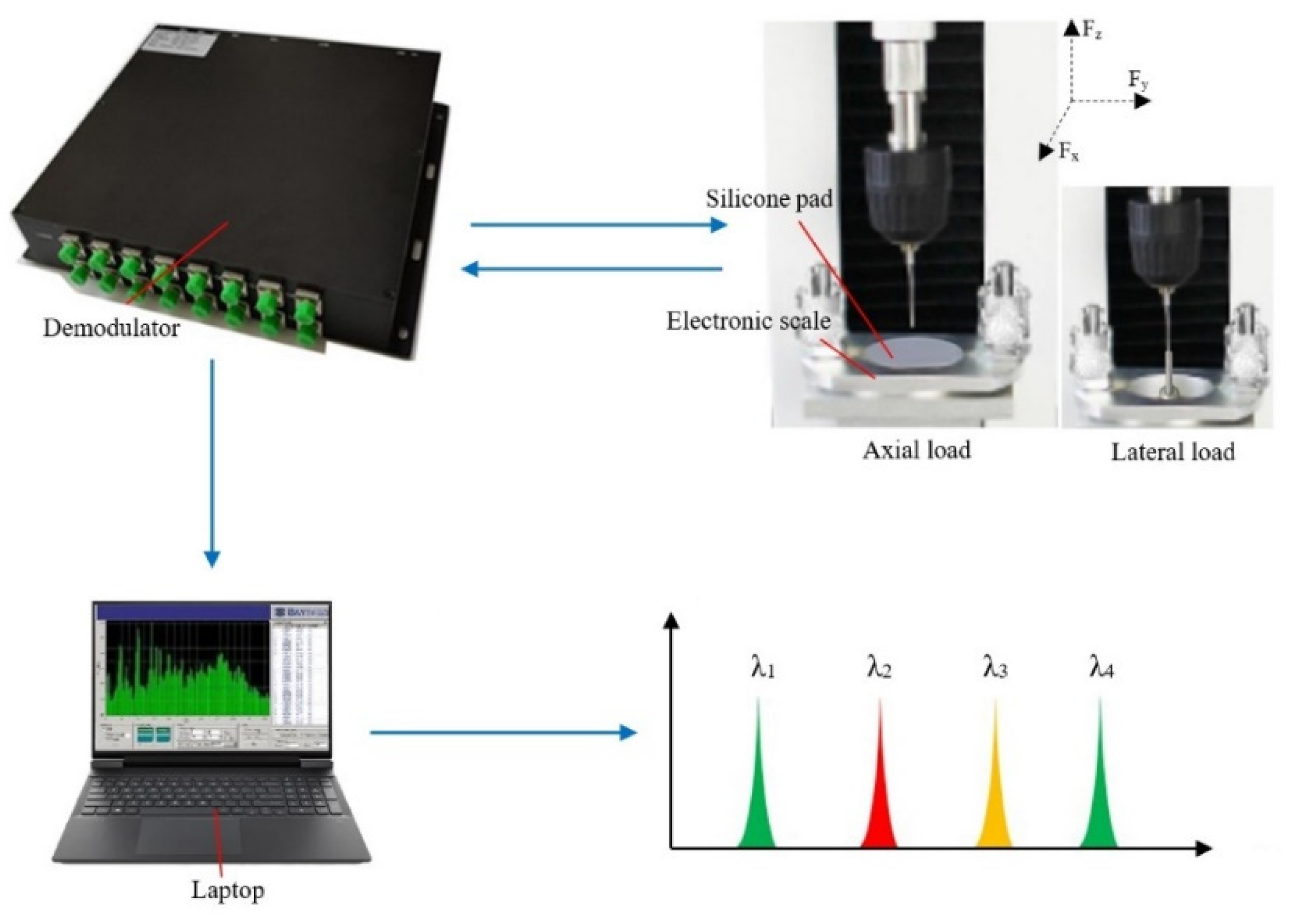
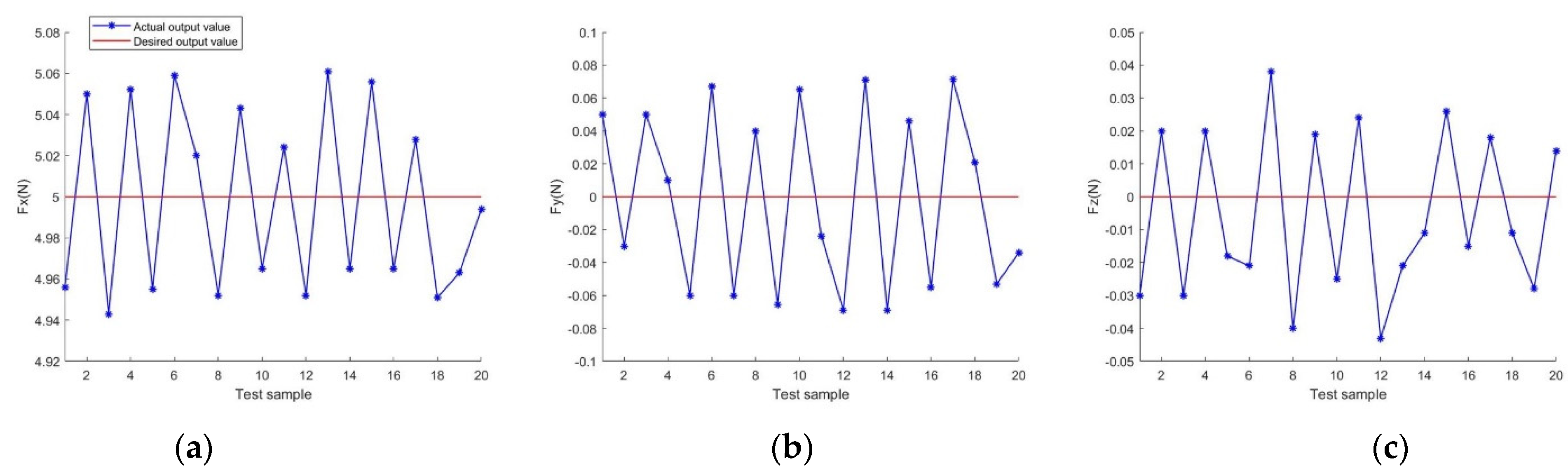
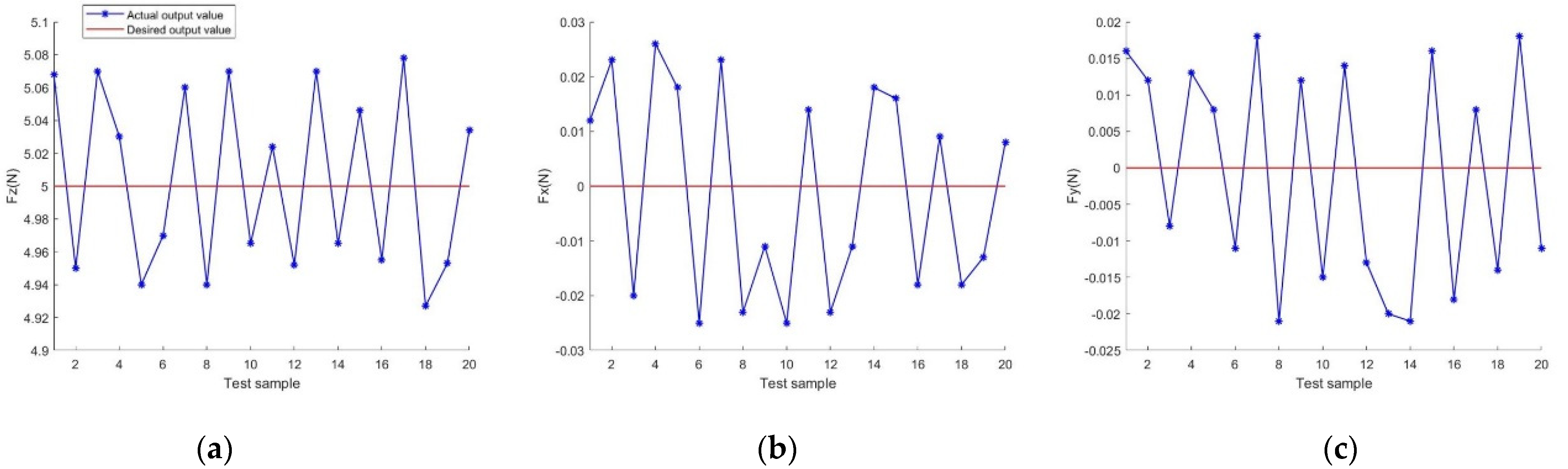
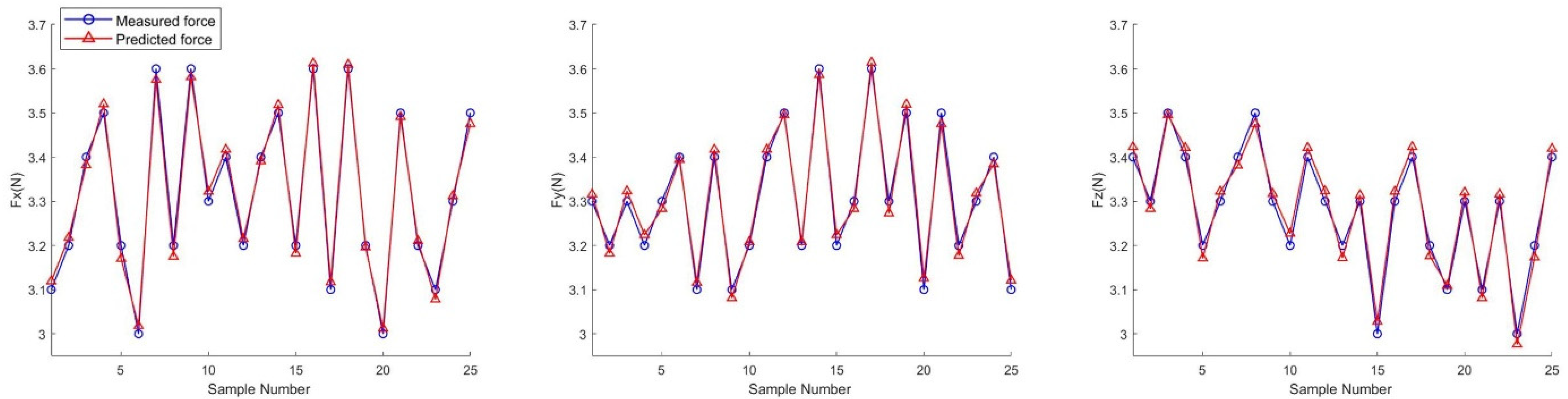
4. Experimental Results

To further verify the performance of the sensor, we constructed a sensor calibration experimental system, as shown in Figure 8. The system consists of a sensor, a force loading platform, a fiber grating demodulator (wavelength 1460~1620 nm, frequency 1 KHz, demodulation accuracy 1 pm) and a host computer. We use the phase mask method to fabricate FBGs and use the UV femtosecond laser to etch them. The UV femtosecond laser parameters are as follows: wavelength 800 nm, pulse width 100 fs, frequency 1 kHz, and maximum pulse energy 4 mJ. The laser changes to UV light with a wavelength of 266 nm after passing through a triplexer. The Gaussian diameter (1/e2) of the Gaussian spot of the femtosecond laser is 6.2 mm. The CPU of our laptop is i7-11370H, and the GPU is RTX3060. Due to the inter-dimensional coupling interference, the output force exists in the unloaded direction, and the inter-dimensional coupling interference needs to be further reduced by the decoupling algorithm. The results of the traditional BP neural network and GOFF-BP neural network iterations are shown in Figure 9. From the figure, we can observe that the improved GOFF-BP neural network converges faster when the training target error of the neural network is approximately the same. The curve in Figure 9b is smoother than the curve in Figure 9a, which indicates that the oscillation of the GOFF-BP neural network during training has also been greatly improved and the overall performance has been enhanced.
The obtained 20 sets of data were fed into the GOFF−BP neural network when the 5N load was applied to the Fx and Fz directions, respectively, and the output values of each channel obtained are shown in Figure 10 and Figure 11, respectively. As can be observed from the figures, the output values of the improved neural network in each channel are very close to the expected values. The output error of GOFF−BP decoupled network is small and has a good decoupling effect.
The measured and predicted values of the sensor are shown in Figure 12 when we applied different forces to the sensor in the X, Y and Z directions, respectively.
To further verify the performance of the sensor, we counted the type I and type II errors of the sensor. Type I error indicates the degree of deviation from the true value of the output value of the force loaded on a single direction of the sensor within the measurement range, and type I error is expressed as
σ I = e i m a x y i F , S
where y i F , S is the full-scale value in the i direction of the sensor and e i m a x is the maximum deviation between the output value in direction i and the true value when force is applied in that direction.
Type II error reflects the degree of influence of unloaded directional coupling interference when the sensor is loaded with a unidirectional force, and the type II error is expressed as
σ II = y j i m a x 2 + y k i m a x 2 y i F , S 2
where y j i m a x and y k i m a x denote the maximum values of coupled disturbances in the i-direction when unidirectional forces are applied in the j and k-directions, respectively. The maximum type I, and type II errors of several current state-of-the-art decoupling algorithms are shown in Table 1 and Table 2, respectively.
From Table 1 and Table 2, it can be observed that the maximum type I error in each direction of the GOFF-BP neural network decoupling algorithm is 1.25% and the maximum type II error is 1.47%. GOFF-BP solves the shortcomings of the traditional BP neural network, which easily falls into local extremes and demonstrates slow convergence, and has some advantages in decoupling accuracy compared with several other decoupling algorithms. The movement of the puncture needle during the puncture procedure is relatively slow, and we can effectively satisfy the monitoring of interactive force information during the procedure by collecting 50 data per second, and the interval between each data collection is actually 20 ms. The time consumption (TC) of each sampling process by the GOFF-BP algorithm is about 2.26 ms, and there is enough time to process the data. The error of the moving average method is about 0.92%, and the output rate of the decoupling algorithm is greater than 99.9%.

5. Discussion

Comprehensive feedback force information detection is very important in puncture diagnosis and treatment procedures. Through force sensing, the surgeon can obtain surgical details that cannot be reflected by visual information during the procedure. When the sensor senses abnormal feedback force during the procedure, the surgeon can adjust the procedure in time, thus improving the safety of the procedure. The structure of the end of the puncture instrument is very small and requires a small force sensor. Fiber grating sensors with a small size and stable chemical properties can meet the requirements of puncture instruments. Ref. [18] proposed an FBG-based needle insertion force sensor for exploring the interaction between the needle and tissue during a puncture. The sensor is highly influenced by temperature, and the sensor error is large when the difference between the ambient temperature and the human body temperature is large. Ref. [19] proposed a fiber optic sensor integrated in the enclosed space of the flexible ureteroscope tip to measure the contact force during ureteroscopy, and the decoupling algorithm of this sensor has a large error.
In this paper, we present a new method to measure the lateral and axial forces on a puncture needle. The three-dimensional force sensor consists of four fiber optic gratings, three of which are affixed to the inner wall of the puncture needle at 120° intervals along the axial direction and one is located at the center of the needle. The FBG at the center is connected with two fiber optic gratings in series, one of which is used to measure the ambient temperature of the sensor, so that the effect of temperature on the sensor can be deducted and the sensor accuracy can be effectively improved. The puncture needle wall is slotted to increase the sensitivity of the sensor to axial forces and to reduce crosstalk between the axial and lateral forces. Traditional neural network models for decoupling multidimensional force sensors suffer from network training oscillations, slow convergence and falling into local extremes. We propose to improve the BP neural network using the particle swarm optimization algorithm, which has the advantages of fast and high accuracy, while retaining the advantages of a BP neural network, and effectively reduces the crosstalk problem between multidimensional forces. In addition, we find that the inter-dimensional coupling of multidimensional force sensors is often nonlinear and the coupling situation is complicated in the application of FBG sensors. The traditional decoupling algorithms can weaken the inter-dimensional coupling of multidimensional force sensors to some extent, but there are problems of incomplete decoupling or poor stability of the decoupling effect. The trained GOFF-BP decoupling algorithm has a good generalization function and can give accurate output signals, even for those input signals whose samples are not concentrated. By continuously adjusting the parameters of the GOFF-BP neural network, good approximation accuracy can be achieved, but the computational effort of the decoupling process does not increase significantly. The integration of this sensor with the surgical platform is also technically feasible, which facilitates the realization of force feedback control of the surgical platform. In addition, the multidimensional force sensor proposed in this paper can also be applied to other minimally invasive surgical instruments that require force sensors.

6. Conclusions

In medical puncture robots, the detection of the interaction force information between the puncture needle and the soft tissue in different directions is very important and can effectively guarantee the safety of the puncture process. In this paper, we designed a three-dimensional FBG-based force sensor to measure the interaction force information of the puncture needle in different directions during venipunctures. We developed a mathematical model to analyze the correlation between the stress and strain of the sensor, and then optimized the structural parameters of the sensor by means of finite element analysis. We propose a BP neural network decoupling algorithm based on the global optimal fitness function, which has the characteristics of fast and accurate finding of optimal solutions and effectively reduces the crosstalk problem between multidimensional forces. The maximum type I error of the sensor in three directions is 1.25% and the maximum type II error is 1.47%. The sensor has good nonlinear decoupling ability and can meet the requirements of multidimensional measurement in the puncture process.

Author Contributions

X.L. created the models, analyzed the results and wrote the manuscript. D.Y. designed the prototype and implemented the experiments. Y.P. and L.Z. reviewed the manuscript. J.L. and Z.L. were involved in the formulation of the overarching research goals and funded the research. All authors have read and agreed to the published version of the manuscript.

Funding

This work was partially supported by the Natural Science Foundation of Chongqing, China (No. cstc2020jcyj-msxmX0702) and the Science and Technology Research Program of Chongqing Municipal Education Commission (Grant No. KJQN202002804) and (Grant KJQN202102806).

Institutional Review Board Statement

Not applicable.

Informed Consent Statement

Not applicable.

Data Availability Statement

Not applicable.

Conflicts of Interest

The authors declare no conflict of interest.

References

  1. Okamura, A.M. Haptics in robot-assisted minimally invasive surgery. In The Encyclopedia of Medical Robotics. Volume 1: Minimally Invasive Surgical Robotics; World Scientific: Singapore, 2019; pp. 317–339. [Google Scholar]
  2. Ranzani, T.; Gerboni, G.; Cianchetti, M.; Menciassi, A. A bioinspired soft manipulator for minimally invasive surgery. Bioinspir. Biomim. 2015, 10, 035008. [Google Scholar] [CrossRef]
  3. Chen, S.; Wang, F.; Lin, Y.; Shi, Q.; Wang, Y. Ultrasound-guided needle insertion robotic system for percutaneous puncture. Int. J. Comput. Assist. Radiol. Surg. 2021, 16, 475–484. [Google Scholar] [CrossRef]
  4. Zhang, W.; Bao, K.; Zheng, L.; Cai, L.; Yan, B.; Yang, R. A robotic puncture system with optical and mechanical feedback under respiratory motion. Int. J. Med. Robot. Comput. Assist. Surg. 2022, 18, e2403. [Google Scholar] [CrossRef]
  5. Guo, S.; Wang, Y.; Xiao, N.; Li, Y.; Jiang, Y. Study on real-time force feedback for a master–slave interventional surgical robotic system. Biomed. Microdev. 2018, 20, 37. [Google Scholar] [CrossRef]
  6. Yu, H.; Wang, H.; Chang, J.; Niu, J.; Wang, F.; Yan, Y.; Tian, H.; Fang, J.; Lu, H. A novel vascular intervention surgical robot based on force feedback and flexible clamping. Appl. Sci. 2021, 11, 611. [Google Scholar] [CrossRef]
  7. Yoon, S.M.; Kim, W.J.; Lee, M.C. Design of bilateral control for force feedback in surgical robot. Int. J. Control Autom. Syst. 2015, 13, 916–925. [Google Scholar] [CrossRef]
  8. Li, K.; Pan, B.; Gao, W.-P.; Feng, H.-B.; Fu, Y.-L.; Wang, S.-G. Miniature 6-axis force/torque sensor for force feedback in robot-assisted minimally invasive surgery. J. Central South Univ. 2015, 22, 4566–4577. [Google Scholar] [CrossRef]
  9. Overtoom, E.M.; Horeman, T.; Jansen, F.W.; Dankelman, J.; Schreuder, H.W. Haptic feedback, force feedback, and force-sensing in simulation training for laparoscopy: A systematic overview. J. Surg. Educ. 2019, 76, 242–261. [Google Scholar] [CrossRef]
  10. Kim, U.; Lee, D.H.; Yoon, W.J.; Hannaford, B.; Choi, H.R. Force sensor integrated surgical forceps for minimally invasive robotic surgery. IEEE Trans. Robot. 2015, 31, 1214–1224. [Google Scholar] [CrossRef]
  11. Bao, X.; Guo, S.; Xiao, N.; Li, Y.; Shi, L. Compensatory force measurement and multimodal force feedback for remote-controlled vascular interventional robot. Biomed. Microdev. 2018, 20, 74. [Google Scholar] [CrossRef]
  12. Leal-Junior, A.G.; Marques, C.; Ribeiro, M.R.N.; Pontes, M.J.; Frizera, A. FBG-embedded 3-D printed ABS sensing pads: The impact of infill density on sensitivity and dynamic range in force sensors. IEEE Sens. J. 2018, 18, 8381–8388. [Google Scholar] [CrossRef]
  13. Leal-Junior, A.; Biazi, V.; Marques, C.; Frizera, A. Force-displacement analysis in diaphragm-embedded fiber bragg grating sensors. Sensors 2022, 22, 5355. [Google Scholar] [CrossRef] [PubMed]
  14. Marques, C.A.; Bilro, L.B.; Alberto, N.J.; Webb, D.J.; Nogueira, R.N. Narrow bandwidth Bragg gratings imprinted in polymer optical fibers for different spectral windows. Opt. Commun. 2013, 307, 57–61. [Google Scholar] [CrossRef]
  15. Woyessa, G.; Theodosiou, A.; Markos, C.; Kalli, K.; Bang, O. Single peak fiber Bragg grating sensors in tapered multimode polymer optical fibers. J. Light. Technol. 2021, 39, 6934–6941. [Google Scholar] [CrossRef]
  16. Ourak, M.; Smits, J.; Esteveny, L.; Borghesan, G.; Gijbels, A.; Schoevaerdts, L.; Douven, Y.; Scholtes, J.; Lankenau, E.; Eixmann, T.; et al. Combined OCT distance and FBG force sensing cannulation needle for retinal vein cannulation: In vivo animal validation. Int. J. Comput. Assist. Radiol. Surg. 2019, 14, 301–309. [Google Scholar] [CrossRef]
  17. Liang, Q.; Zou, K.; Long, J.; Jin, J.; Zhang, D.; Coppola, G.; Sun, W.; Wang, Y.; Ge, Y. Multi-component FBG-based force sensing systems by comparison with other sensing technologies: A review. IEEE Sens. J. 2018, 18, 7345–7357. [Google Scholar] [CrossRef]
  18. Sun, K.; Li, M.; Wang, S.; Zhang, G.; Liu, H.; Shi, C. Development of a fiber Bragg grating-enabled clamping force sensor integrated on a grasper for laparoscopic surgery. IEEE Sens. J. 2021, 21, 16681–16690. [Google Scholar] [CrossRef]
  19. Lai, W.; Cao, L.; Liu, J.; Tjin, S.C.; Phee, S.J. A three-axial force sensor based on fiber Bragg gratings for surgical robots. IEEE/ASME Trans. Mechatr. 2021, 27, 777–789. [Google Scholar] [CrossRef]
  20. Lv, C.; Wang, S.; Shi, C. A high-precision and miniature fiber Bragg grating-based force sensor for tissue palpation during minimally invasive surgery. Ann. Biomed. Eng. 2020, 48, 669–681. [Google Scholar] [CrossRef]
  21. Zhang, T.; Chen, B.; Zuo, S. A novel 3-DOF force sensing microneedle with integrated fiber Bragg grating for microsurgery. IEEE Trans. Ind. Electron. 2021, 69, 940–949. [Google Scholar] [CrossRef]
  22. Shi, C.; Tang, Z.; Wang, S. Design and experimental validation of a fiber Bragg grating-enabled force sensor with an ortho-planar spring-based flexure for surgical needle insertion. IEEE Trans. Med. Robot. Bionics 2021, 3, 362–371. [Google Scholar] [CrossRef]
  23. Deng, Y.; Yang, T.; Dai, S.; Song, G. A miniature triaxial fiber optic force sensor for flexible ureteroscopy. IEEE Trans. Biomed. Eng. 2020, 68, 2339–2347. [Google Scholar] [CrossRef]
  24. Chen, W.; Yang, S.; Hu, Q.; Song, A. Design of a wireless six-axis wrist force sensor for teleoperation robots. In Proceedings of the International Conference on Intelligent Robotics and Applications, Macau, China, 4–8 November 2019; Springer: Cham, Switzerland, 2019; pp. 702–713. [Google Scholar]
  25. Xiong, L.; Guo, Y.; Jiang, G.; Zhou, X.; Liu, H. An FBG-based 2-DOF force sensing intraocular lens positioning hook for cataract surgery. IEEE Photon. Technol. Lett. 2019, 31, 1674–1677. [Google Scholar] [CrossRef]
  26. Aiguo, S.; Liyue, F.U. Multi-dimensional force sensor for haptic interaction: A review. Virtual Real. Intell. Hardw. 2019, 1, 121–135. [Google Scholar]
  27. Cappelleri, D.J.; Krishnan, G.; Kim, C.; Kumar, V.; Kota, S. Toward the design of a decoupled, two-dimensional, vision-based μN force sensor. J. Mech. Robot. 2010, 2, 021010. [Google Scholar] [CrossRef]
  28. Zhou, S.; Sun, J.; Chen, W.; Li, W.; Gao, F. Method of designing a six-axis force sensor for stiffness decoupling based on Stewart platform. Measurement 2019, 148, 106966. [Google Scholar] [CrossRef]
  29. Kang, M.K.; Lee, S.; Kim, J.H. Shape optimization of a mechanically decoupled six-axis force/torque sensor. Sens. Actuator A Phys. 2014, 209, 41–51. [Google Scholar] [CrossRef]
  30. Zhao, Y.; Jiao, L.; Weng, D.; Zhang, D.; Zheng, R. Decoupling principle analysis and development of a parallel three-dimensional force sensor. Sensors 2016, 16, 1506. [Google Scholar] [CrossRef]
  31. Liu, Q.; Li, D.; Ge, S.S.; Ji, R.; Ouyang, Z.; Tee, K.P. Adaptive bias RBF neural network control for a robotic manipulator. Neurocomputing 2021, 447, 213–223. [Google Scholar] [CrossRef]
  32. Ma, J.; Song, A.; Xiao, J. A robust static decoupling algorithm for 3-axis force sensors based on coupling error model and ε-SVR. Sensors 2012, 12, 14537–14555. [Google Scholar] [CrossRef]
  33. Liang, Q.; Wu, W.; Coppola, G.; Zhang, D.; Sun, W.; Ge, Y.; Wang, Y. Calibration and decoupling of multi-axis robotic force/moment sensors. Robot. Comput.-Integr. Manuf. 2018, 49, 301–308. [Google Scholar] [CrossRef]
  34. Sahota, J.K.; Gupta, N.; Dhawan, D. Fiber Bragg grating sensors for monitoring of physical parameters: A comprehensive review. Opt. Eng. 2020, 59, 060901. [Google Scholar] [CrossRef]
  35. Broadway, C.; Min, R.; Leal-Junior, A.G.; Marques, C.; Caucheteur, C. Toward commercial polymer fiber Bragg grating sensors: Review and applications. J. Light. Technol. 2019, 37, 2605–2615. [Google Scholar] [CrossRef]
  36. Li, J.; Wang, C.; Mao, Z.; Liu, Y.; Wang, Z.; Liu, H. A compact FBG-based triaxial force sensor with parallel helical beams for robotic-assisted surgery. IEEE Trans. Instrum. Meas. 2022, 71, 1–9. [Google Scholar] [CrossRef]
Figure 1. FBG sensing schematic. (a) Incident light; (b) Transmission light; (c) Reflect light; (d) Reflected light after FBG is subjected to strain or temperature change.
Photonics 09 00630 g001
Figure 2. Three-dimensional force FBG sensor structure diagram. (a) Structure and assembly overview; (b) cross-section; (c) prototype.
Photonics 09 00630 g002
Figure 3. Equivalent models of force sensors. (a) Axial spring model, (b) transverse cantilever beam model.
Photonics 09 00630 g003
Figure 4. Three slotted designs for sensors. (a) Coil spring design; (b) cantilever beam design; (c) parallel slot design.
Photonics 09 00630 g004
Figure 5. Strain contours of force sensor. (a) 8 N in the axial direction; (b) 8 N in the x-direction; (c) 8 N in the y-direction.
Photonics 09 00630 g005
Figure 6. Laser cutting error in relation to the location of the peak hot spot. (a) Standard cut, (b) cutting error of +0.05 mm, (c) cutting error of −0.05 mm.
Photonics 09 00630 g006
Figure 7. Structure of BP neural network with three-dimensional force decoupling.
Photonics 09 00630 g007
Figure 8. The sensor calibration platform.
Photonics 09 00630 g008
Figure 9. Iterative optimization curve: (a) BP neural network; (b) GOFF−BP neural network.
Photonics 09 00630 g009
Figure 10. Output values of each channel when 5N load is applied in Fx direction. (a) Fx channel output value; (b) Fy channel output value; (c) Fz channel output value.
Photonics 09 00630 g010
Figure 11. Output values of each channel when 5N load is applied in Fz direction. (a) Fz channel output value; (b) Fx channel output value; (c) Fy channel output value.
Photonics 09 00630 g011
Figure 12. The measured and predicted values of the sensor when different forces are applied to the sensor in X, Y and Z directions, respectively.
Photonics 09 00630 g012
Table 1. Comparison of maximum type I errors of decoupling algorithm.
Decoupling MethodFxFyFzTC
Before decoupling3.623.274.150 ms
BP 1.541.411.731.87 ms
BRFNN1.421.431.692.63 ms
SVR1.511.381.742.08 ms
ELM1.371.241.542.45 ms
GOFF-BP1.251.181.562.26 ms
Table 2. Comparison of maximum type II errors of decoupling algorithm.
Decoupling MethodFxFyFzTC
Before decoupling6.71 7.242.550 ms
BP1.841.921.531.87 ms
BRFNN1.461.541.172.63 ms
SVR1.571.591.242.08 ms
ELM1.421.511.032.45 ms
GOFF-BP1.381.470.942.26 ms
Publisher’s Note: MDPI stays neutral with regard to jurisdictional claims in published maps and institutional affiliations.

