Article

A Novel System of Mixed RF/FSO UAV Communication Based on MRR and RIS by Adopting Hybrid Modulation

1
Guangdong Provincial Key Laboratory of Nanophotonic Functional Materials and Devices, Guangzhou 510006, China
2
School of Information and Optoelectronic Science and Engineering, South China Normal University, Guangzhou 510006, China
*
Author to whom correspondence should be addressed.
Photonics 2022, 9(6), 379; https://doi.org/10.3390/photonics9060379
Submission received: 27 April 2022 / Revised: 18 May 2022 / Accepted: 24 May 2022 / Published: 26 May 2022
(This article belongs to the Special Issue Optical Wireless Communications Systems)

Abstract

:
In this paper, we propose a mixed radio frequency (RF)/free space optical (FSO) unmanned aerial vehicle (UAV) communication system, based on modulating retro-reflector (MRR) and reconfigurable intelligent surface (RIS), which adopts the hybrid L-ary pulse position modulation-binary phase shift keying-subcarrier intensity modulation (L-PPM-BPSK-SIM). More specifically, the RF channel follows Rayleigh distribution, while the FSO channel obeys Gamma–Gamma distribution that considers atmospheric turbulence and pointing error. For decode-and-forward (DF) relay, the MRR is installed on the UAV to reduce its weight, size, and power consumption. In particular, the RIS is used as user terminal along with the RF signal generator to achieve signal enhancement. Based on this, closed expressions for the outage probability, average bit error rate (BER) and average channel capacity of the end-to-end uplink and downlink are derived. Numerical results confirm that while the relay limitation is solved by MRR, RIS significantly reduces the outage probability and average BER as well as obviously increases the average channel capacity. Furthermore, the hybrid L-PPM-BPSK-SIM with average symbol length greater than eight can effectively improve the average BER performance of the system.

1. Introduction

Free space optical (FSO) communication has attracted extensive research due to its high security, fast data rate transmission, large bandwidth, free spectrum licensing and ease of deployment [1,2]. FSO can be applied in many scenarios such as remote sensing, radio astronomy, military, disaster recovery, last mile access, wireless cellular network backhauls, etc. [3,4]. However, the performance of FSO communication is susceptible to interference from atmospheric conditions. In contrast, radio frequency (RF) communication is not sensitive to atmospheric turbulence, but its spectrum resources are not sufficient. Therefore, a mixed RF/FSO system is available to combine the advantages of both to effectively improve the performance of the overall system [5]. Traditional mixed RF/FSO communication does not offer flexibility due to the fixed deployment of communication equipment. Thus, the application of mobile relay in mixed RF/FSO is very necessary. Mobile relays, such as unmanned aerial vehicles (UAVs), are particularly suitable for emergency, temporary events or special scenarios, such as emergency response, agricultural areas, volcano detection, marine communications, etc. [6]. However, factors such as the power consumption and flight time of UAV are a major challenge for UAV communication [7]. Importantly, the mobility of UAV can provide new opportunities for improving performance by dynamically adjusting relay position to best suit the environment for communication.
Recently, modulating retro-reflector (MRR)’s FSO communication has been widely employed in UAV, optical wireless sensing networks, and spacecraft communication [8]. Specifically, MRR usually consists of an optical modulator and a passive retro-reflector, and the most commonly used retro-reflectors are the corner cube reflector (CCR) and the cat’s eye reflector (CER) [9]. Compared to the traditional FSO communication, MRR FSO system offers significant advantage in terms of reducing the weight, size, and power constraints at one end of the FSO link [10]. In a conventional FSO communication system, precise ATP (acquisition, tracking, and pointing) system and laser transmitter must be deployed at both ends of the FSO link, which is limited when the UAV is working as a relay. However, when the MRR is installed at the relay, the ATP system and laser transmitter only needs to be placed at the other end of the FSO link, so the limitation problem of the relay is solved [11]. In [12], the effect of atmospheric turbulence on the performance of the MRR FSO system was investigated under correlated Gamma–Gamma fading channels, and adaptive threshold technique was chosen to improve the bit error rate (BER) performance. In [13], the BER of the MRR FSO system was analyzed over single and double Gamma–Gamma fading channels. Moreover, the outage probability, average BER and average channel capacity of the MRR FSO communication system were evaluated under different atmospheric turbulence in [14,15,16].
Meanwhile, in order to improve the performance of the communication system by enhancing the signal, the reconfigurable intelligent surface (RIS) is applied in RF communication [17]. The RIS is an emerging technology to improve the performance of wireless communication and will have promising applications in the internet of things (IoT) as well as in 6G [18]. More specifically, the RIS is an artificial surface composed of electromagnetic materials. It adjusts the reflection of incident electromagnetic waves through low-cost and simple passive reflection elements to realize the intelligent reconstruction of the signal propagation environment, thereby enhancing the signal and improving the performance of the wireless communication system [19]. At present, RIS is mainly used in two transmission scenarios. One is the RIS-assisted scenario, where the RIS is deployed on the building between the signal source and the receiver. The other is the RIS-equipped scenario, where the RIS is placed together with the RF signal generator as a RF source. The outage probability, average BER, and average channel capacity of the RIS-assisted dual-hop RF UAV communication system were analyzed in [20], and it was found that RIS did improve the performance of the system. Nonetheless, in the RIS-assisted case, it was observed that the analytic and the simulated results matched well only when the number of reflective elements of the RIS was large [21]. By contrast, in [22], the RIS-equipped scenario reflected better diversity gain and coding gain. Moreover, the theoretical and simulated results also matched well when the number of reflective elements was low.
Additionally, the modulation technique has a great impact on the BER performance of the communication system [23]. There have been many studies using modulation techniques to improve communication performance. Compared to traditional modulation schemes, the hybrid modulation is prominent. In [24], the authors applied M-ary quadrature amplitude modulation multi-pulse pulse-position modulation (QAM-MPPM) to the FSO system and found that the average BER performance was significantly better than that of the conventional scheme. Additionally, the BER of the FSO communication system by using hybrid pulse position modulation-binary phase shift keying-subcarrier intensity modulation (PPM-BPSK-SIM) was investigated in [25,26,27]. Moreover, the hybrid L-ary pulse position modulation-minimum shift keying-subcarrier intensity modulation (L-PPM-MSK-SIM) was adopted in deep space wireless optical communication system to improve the BER performance [28].
Inspired by the above, we apply MRR and RIS to the mixed RF/FSO UAV communication system, where MRR solves the limitation of UAV relay and RIS achieves signal enhancement. Moreover, the RIS-equipped scheme has better diversity gain and coding gain. In practical application scenarios, the user side needs to take into account factors such as size, which requires that the RIS does not have too many reflective elements, and the RIS-equipped scheme simulates well with a smaller number of reflective elements, which is not the case with the RIS-assisted scheme. The use of UAV as mobile relay allows for increased flexibility in communication, can be better applied to unexpected and occasional events, and the special operating principle of MRR can largely address the inherent limitations of UAV. As far as we know, there are rather few studies on mixed RF/FSO systems based on MRR, and even fewer studies that consider both atmospheric turbulence and pointing error. More importantly, the theoretical research combining MRR and RIS in the existing literature is still in a vacuum. Besides, we raise the BER performance of the system by the hybrid L-PPM-BPSK-SIM scheme. In the existing research on MRR FSO systems, only the downlink is mostly investigated, in our work, the end-to-end uplink and end-to-end downlink are comprehensively studied and the differences between them are analyzed. On this basis, considering the atmospheric turbulence and pointing error, the outage probability, average BER, and average channel capacity expressions of the mixed RF/FSO system based on MRR and RIS are derived.
The remainder of this paper is organized as follows: Section 2 presents the mixed RF/FSO UAV dual-hop system based on MRR and RIS. Section 3 further derives closed expressions for the end-to-end outage probability, average BER, and average channel capacity of the system. Then in Section 4, numerical results are provided. Finally, Section 5 offers some concluding remarks.

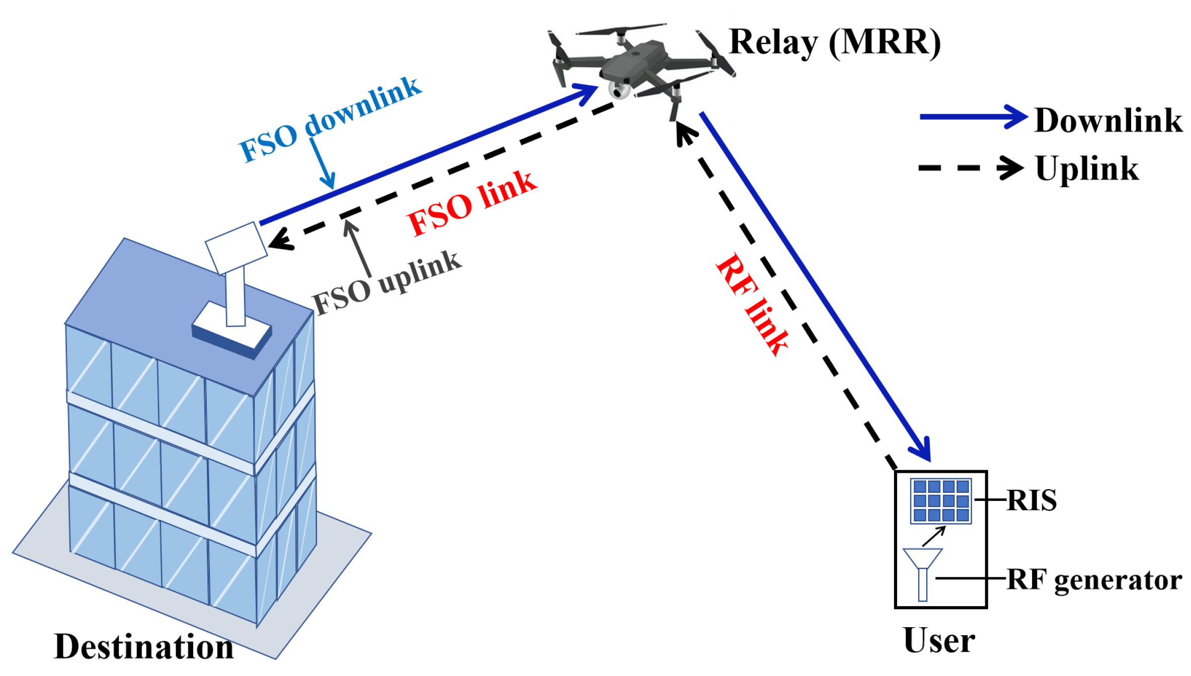
2. System and Theoretical Model

As shown in Figure 1, we consider a mixed RF/FSO UAV dual-hop communication system based on MRR and RIS, where MRR is installed at the UAV relay and RIS acts as the RF source (i.e., the user) put together with the RF signal generator. Considering scenarios where the user end is indoors, or outdoors where it is obscured by buildings, trees, etc., we use the Rayleigh distribution commonly used in multipath fading without direct line of sight in the RF channel [29]. For the FSO link, the classical Gamma–Gamma distribution was chosen because of its good fit with measurements over a wide range of turbulent conditions (weak to strong) [30]. The end-to-end uplink of the system is the transmission of data from the user to the destination (i.e., User → Relay → Destination), while the end-to-end downlink is the reverse (i.e., Destination → Relay → User). At the UAV relay, the decode-and-forward (DF) protocol is adopted. The addition of MRR allows the ATP system and laser transmitter to exist only at the destination, thus reducing the weight, size, and power consumption of the UAV relay. Moreover, the RIS in the RF link, with many passive reflective elements to enhance the signal, provides a significant improvement in system performance.
In this system, taking the end-to-end uplink as an example, the signal received at the relay is expressed as y 1 = h 1 x + n 1 , and the signal received at the destination is denoted as y 2 = h 2 y 1 + n 2 = h 2 ( h 1 x + n 1 ) + n 2 , where x is the signal source, h 1 and h 2 are the channel coefficients of RF and FSO links, n 1 and n 2 are the additive Gaussian white noise (AWGN). Furthermore, the working principle in the end-to-end downlink is similar. In the downlink, the information received by the user is also related to the channel coefficients of the RF and FSO links.

2.1. RF Link

In this mixed RF/FSO system, the RF channel experiences Rayleigh distribution, the RIS and the RF signal generator are put together as the RF source, which implies that the channel attenuation between them can be ignored. Thus, the probability density function (PDF) of the signal-to-noise ratio (SNR) is given by [31]:
f γ 1 ( γ 1 ) γ 1 N 1 e γ 1 B γ ¯ 1 ( B γ ¯ 1 ) N ( N 1 ) ! ,
where B = 1 + ( N 1 ) Γ 2 ( 3 2 ) , γ 1 and γ ¯ 1 are the instantaneous SNR and the average SNR of RF link, respectively. Γ ( · ) is the Gamma function, and N is the number of passive reflective elements in the RIS. Further, the cumulative distribution function (CDF) of the RF link SNR is written as [22]:
F γ 1 ( γ 1 ) 1 e γ 1 B γ ¯ 1 m = 0 N 1 γ 1 m ( B γ ¯ 1 ) m m ! .

2.2. FSO Link

The FSO channel follows the Gamma–Gamma distribution considering atmospheric turbulence and pointing error. We consider the UAV relay at low altitude, where MRR is installed.The intensity modulation/direct detection (IM/DD) technique is adopted at the optical receiver. Specifically, the retro-reflector in the MRR we use is the CCR. Note that the incident beam enters the CCR after being modulated by the optical modulator, then is reflected by mutually perpendicular reflective surfaces in turn, and finally exits in the opposite direction to the incident beam. The advantage is that the ATP system and the laser transmitter can be omitted at the relay. However, the use of MRR at the relay leads to differences between the uplink and downlink of the system, which is mainly reflected in the FSO link. For bidirectional communication in our system, the FSO uplink refers to the data transmission from the relay to the destination (i.e., Relay → Destination), while the FSO downlink is the opposite (i.e., Destination → Relay).
Therefore, the principle of the FSO uplink and the FSO downlink is detailed in Figure 2. The FSO uplink implements the data transmission from the relay to the destination. Note that the data to be transmitted at the relay are sent by the user over the RF link. When the relay receives the data from the user, the next step is to send the data from the relay to the destination. First, the destination needs to transmit a beam without data to the relay through the forward path (i.e., Destination → Relay), and then the relay loads the data onto the optical carrier in the forward path through the optical modulator. Hence, the backward path (i.e., Relay → Destination) carries the data and reflects it to the destination via MRR.
For the FSO downlink, it is the implementation of the data transmission from the destination to the relay. The principle is the same as that of traditional FSO communication. That is, data are loaded into the beam at the destination and then sent to the relay via the FSO downlink.
Since the FSO uplink experiences twice the distance from the destination to the relay, the channel coefficient of the FSO uplink is expressed as:
h 2 = h f h b ,
where h f and h b are the channel coefficients of the forward path and the backward path, respectively. Owing to the characteristics of MRR, the forward path considers atmospheric turbulence and pointing error, while the backward path takes atmospheric turbulence into account. Hence, the channel coefficients of the forward path and the backward path are written as h f = h a 1 h p , h b = h a 2 , where h a 1 and h a 2 are the channel coefficients due to atmospheric turbulence, and h p is the channel coefficient caused by the pointing error.
Therefore, the PDF of instantaneous SNR for the FSO uplink is expressed as [32]:
f γ 2 ( γ 2 ) = ξ 2 2 γ 2 Γ ( α 1 ) Γ ( α 2 ) Γ ( β 1 ) Γ ( β 2 ) G 5 , 0 1 , 5 α 1 α 2 β 1 β 2 A 0 γ 2 γ ¯ 2 ξ 2 + 1 ξ 2 , α 1 , α 2 , β 1 , β 2 ,
where γ 2 and γ ¯ 2 are the instantaneous SNR and the average SNR of FSO link. ξ = ω e q / 2 σ s denotes the pointing error parameter, ω e q is the equivalent beamwidth, σ s is the jitter standard deviation. A 0 = ( e r f ( ν ) ) 2 is the received optical power at radial displacement of 0, ν = a / ω z π / 2 , a is the radius of the optical receiver, ω z is the beamwidth at distance from the laser emitter. G ( · ) is the Meijer’s G function. α 1 , β 1 are the parameters of atmospheric turbulence in the forward path, and α 2 , β 2 are the parameters of atmospheric turbulence in the backward path, which is calculated by (5) and (6) as below [33].
α i = exp 0.49 σ R 2 ( 1 + 1.11 σ R 12 / 5 ) 7 / 6 1 1 ,
β i = exp 0.51 σ R 2 ( 1 + 0.69 σ R 12 / 5 ) 5 / 6 1 1 ,
where σ R 2 = 1.23 C n 2 K 7 / 6 d 11 / 6 is the Rytov variance, C n 2 is the atmospheric refractive index structure parameter, K = 2 π / λ is the wave number, λ is the wavelength, d = ( h h ) / sin θ is the FSO propagation distance, h is the height of the UAV, h is the height of the optical receiver at the destination and θ is the angle between the FSO link and the horizontal direction.
By integrating (4), the CDF of the instantaneous SNR for the FSO uplink can be obtained as [32]:
F γ 2 ( γ 2 ) = ξ 2 Γ ( α 1 ) Γ ( α 2 ) Γ ( β 1 ) Γ ( β 2 ) G 5 , 1 2 , 6 α 1 α 2 β 1 β 2 A 0 γ 2 γ ¯ 2 1 , ξ 2 + 1 ξ 2 , α 1 , α 2 , β 1 , β 2 , 0 .
In the FSO downlink, the experienced atmospheric channel distance is the distance from the destination to the relay. Thus, the PDF of the instantaneous SNR for the FSO downlink can be represented as [34]:
f γ 2 ( γ 2 ) = ξ 2 2 γ 2 Γ ( α 3 ) Γ ( β 3 ) G 3 , 0 1 , 3 α 3 β 3 γ 2 γ ¯ 2 ξ 2 + 1 ξ 2 , α 3 , β 3 ,
where α 3 and β 3 are the atmospheric turbulence parameters for the FSO downlink.
Similarly, by integrating (8), the CDF of the instantaneous SNR for the FSO downlink is derived as [35]:
F γ 2 ( γ 2 ) = ξ 2 Γ ( α 3 ) Γ ( β 3 ) G 3 , 1 2 , 4 α 3 β 3 γ 2 γ ¯ 2 1 , ξ 2 + 1 ξ 2 , α 3 , β 3 , 0 .

2.3. CDF of End-to-End SNR

In the dual-hop communication system using DF protocol, γ = min ( γ 1 , γ 2 ) [36,37], where γ is the instantaneous end-to-end SNR of the system, γ 1 and γ 2 are the instantaneous SNR of the RF and FSO links, respectively. Therefore, the CDF of end-to-end SNR is expressed as [38]:
F γ ( γ ) = 1 ( 1 F γ 1 ( γ ) ) ( 1 F γ 2 ( γ ) ) = F γ 1 ( γ ) + F γ 2 ( γ ) F γ 1 ( γ ) F γ 2 ( γ ) .
Substituting (2) and (7) into (10), the CDF of end-to-end SNR for the system uplink is obtained as:
F γ ( γ ) = 1 e γ B γ ¯ 1 m = 0 N 1 γ m ( B γ ¯ 1 ) m m ! 1 + W × G 5 , 1 2 , 6 α 1 α 2 β 1 β 2 A 0 γ γ ¯ 2 ϕ 1 ϕ 2 ,
where W = ξ 2 Γ ( α 1 ) Γ ( α 2 ) Γ ( β 1 ) Γ ( β 2 ) ; ϕ 1 = 1 , ξ 2 + 1 ; ϕ 2 = ξ 2 , α 1 , α 2 , β 1 , β 2 , 0 .
Similarly, substituting (2) and (9) into (10), the CDF of end-to-end SNR for the system downlink can be given by:
F γ ( γ ) = 1 e γ B γ ¯ 1 m = 0 N 1 γ m ( B γ ¯ 1 ) m m ! 1 + ξ 2 Γ ( α 3 ) Γ ( β 3 ) × G 3 , 1 2 , 4 α 3 β 3 γ γ ¯ 2 1 , ξ 2 + 1 ξ 2 , α 3 , β 3 , 0 .

3. Performance Analysis

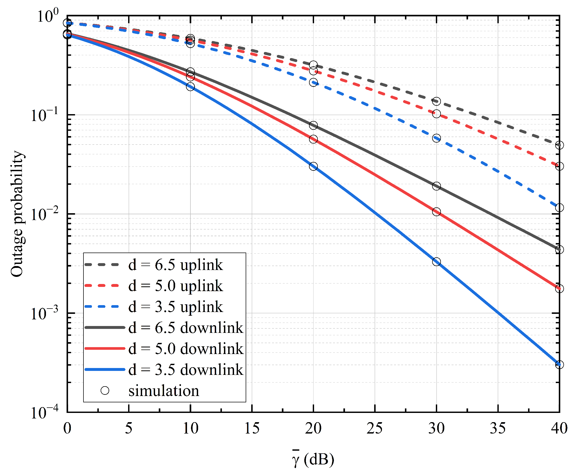
3.1. Outage Probability

The outage probability is a standard performance metric in wireless communication and refers to the probability that the end-to-end SNR γ falls below a specified threshold γ t h resulting in an interruption of data transmission. It is expressed as [39,40]:
P o u t ( γ < γ t h ) = F γ ( γ t h ) .

3.1.1. End-to-End Uplink

By substituting (11) into (13), the outage probability of the end-to-end uplink can be obtained as:
P o u t _ u p = 1 e γ t h B γ ¯ 1 m = 0 N 1 γ t h m ( B γ ¯ 1 ) m m ! 1 + W × G 5 , 1 2 , 6 α 1 α 2 β 1 β 2 A 0 γ t h γ ¯ 2 ϕ 1 ϕ 2 .

3.1.2. End-to-End Downlink

Similarly, by substituting (12) into (13), the outage probability of the end-to-end downlink is written as:
P o u t _ d o w n = 1 e γ t h B γ ¯ 1 m = 0 N 1 γ t h m ( B γ ¯ 1 ) m m ! 1 + ξ 2 Γ ( α 3 ) Γ ( β 3 ) × G 3 , 1 2 , 4 α 3 β 3 γ t h γ ¯ 2 φ 1 φ 2 ,
where φ 1 = 1 , ξ 2 + 1 ; φ 2 = ξ 2 , α 3 , β 3 , 0 .

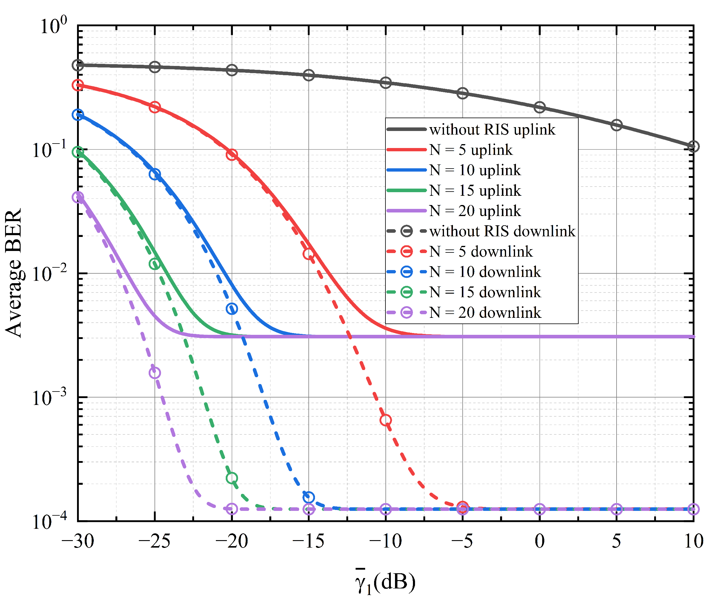
3.2. Average Bit Error Rate

The average BER is an intuitive way to evaluate the impact of modulation scheme on communication system. Here, we employ the hybrid modulation to improve the performance of the system. PPM-BPSK-SIM is a combination of PPM and BPSK-SIM schemes, where the information symbols are modulated into parallel signals by the PPM encoder, converted into high-rate serial signals and then transferred to the BPSK modulator. For L-PPM, a data symbol consists of L time slots, where L is the average symbol length. The conditional BER of L-PPM-BPSK-SIM is expressed as P e _ L P P M B P S K S I M = 1 2 e r f c γ L log 2 L γ L log 2 L 4 2 4 2 [41,42,43], where e r f c · is the complementary error function. The DF scheme is employed in the UAV relay of the mixed RF/FSO UAV dual-hop system, so the average BER is expressed as [44]:
P e = P 1 + P 2 2 P 1 P 2 ,
where P 1 and P 2 are the average BER of the RF link and FSO link, respectively. By using e r f c x = 1 π G 2 , 0 1 , 2 x 2 1 0 , 1 / 2 and e x = G 1 , 0 0 , 1 x 0 [45], the average BER of the RF link using hybrid L-PPM-BPSK-SIM can be obtained as:
P 1 = 0 1 2 e r f c γ L log 2 L 4 2 f γ 1 ( γ ) d γ = 1 2 π ( N 1 ) ! G 2 , 1 2 , 2 L log 2 L B γ ¯ 1 32 1 N , 1 0 , 1 / 2 .

3.2.1. End-to-End Uplink

The average BER of FSO uplink using hybrid L-PPM-BPSK-SIM is derived as:
P 2 = 0 1 2 e r f c γ L log 2 L 4 2 f γ 2 ( γ ) d γ = ξ 2 2 ( α 1 + α 2 + β 1 + β 2 6 ) π 3 / 2 Γ ( α 1 ) Γ ( α 2 ) Γ ( β 1 ) Γ ( β 2 ) G 10 , 2 4 , 11 α 1 2 α 2 2 β 1 2 β 2 2 8 A 0 2 L log 2 L γ ¯ 2 κ 1 κ 2 ,
where κ 1 = 1 , 1 2 , ξ 2 + 1 2 , ξ 2 + 2 2 ; κ 2 = ξ 2 2 , ξ 2 + 1 2 , α 1 2 , α 1 + 1 2 , α 2 2 , α 2 + 1 2 , β 1 2 , β 1 + 1 2 , β 2 2 , β 2 + 1 2 , 0 . Substituting (17) and (18) into (16) and using the extended generalized bivariate Meijer’s G function (EGBMGF) [46], the average BER of the end-to-end uplink is obtained as:
P u = 1 2 π N 1 ! G 2 , 1 2 , 2 L log 2 L B γ ¯ 1 32 1 N , 1 0 , 1 / 2 + ξ 2 2 ( α 1 + α 2 + β 1 + β 2 6 ) π 3 / 2 Γ ( α 1 ) Γ ( α 2 ) Γ ( β 1 ) Γ ( β 2 ) × G 10 , 2 4 , 11 α 1 2 α 2 2 β 1 2 β 2 2 8 A 0 2 L log 2 L γ ¯ 2 κ 1 κ 2 1 N 1 ! π × G 0 , 0 : 2 , 1 : 10 , 2 0 , 0 : 2 , 2 : 4 , 11 1 N , 1 0 , 1 / 2 κ 1 κ 2 L log 2 L B γ ¯ 1 32 , α 1 2 α 2 2 β 1 2 β 2 2 8 A 0 2 L log 2 L γ ¯ 2 .

3.2.2. End-to-End Downlink

The average BER of FSO downlink using hybrid L-PPM-BPSK-SIM is expressed as:
P 2 = 0 1 2 e r f c γ L log 2 L 4 2 f γ 2 ( γ ) d γ = ξ 2 2 ( α 3 + β 3 4 ) π 3 / 2 Γ ( α 3 ) Γ ( β 3 ) G 6 , 2 4 , 7 2 α 3 2 β 3 2 L log 2 L γ ¯ 2 θ 1 θ 2 ,
where θ 1 = 1 , 1 2 , ξ 2 + 1 2 , ξ 2 + 2 2 ; θ 2 = ξ 2 2 , ξ 2 + 1 2 , α 3 2 , α 3 + 1 2 , β 3 2 , β 3 + 1 2 , 0 . Substituting (17) and (20) into (16), the average BER of the end-to-end downlink is written as:
P d = 1 2 π N 1 ! G 2 , 1 2 , 2 L log 2 L B γ ¯ 1 32 1 N , 1 0 , 1 / 2 + ξ 2 2 α 3 + β 3 4 π 3 2 Γ ( α 3 ) Γ ( β 3 ) G 6 , 2 4 , 7 2 α 3 2 β 3 2 γ ¯ 2 L log 2 L θ 1 θ 2 2 N 1 ! π G 0 , 0 : 2 , 1 : 6 , 2 0 , 0 : 2 , 2 : 4 , 7 1 N , 1 0 , 1 / 2 θ 1 θ 2 L log 2 L B γ ¯ 1 32 , 2 α 3 2 β 3 2 γ ¯ 2 L log 2 L .

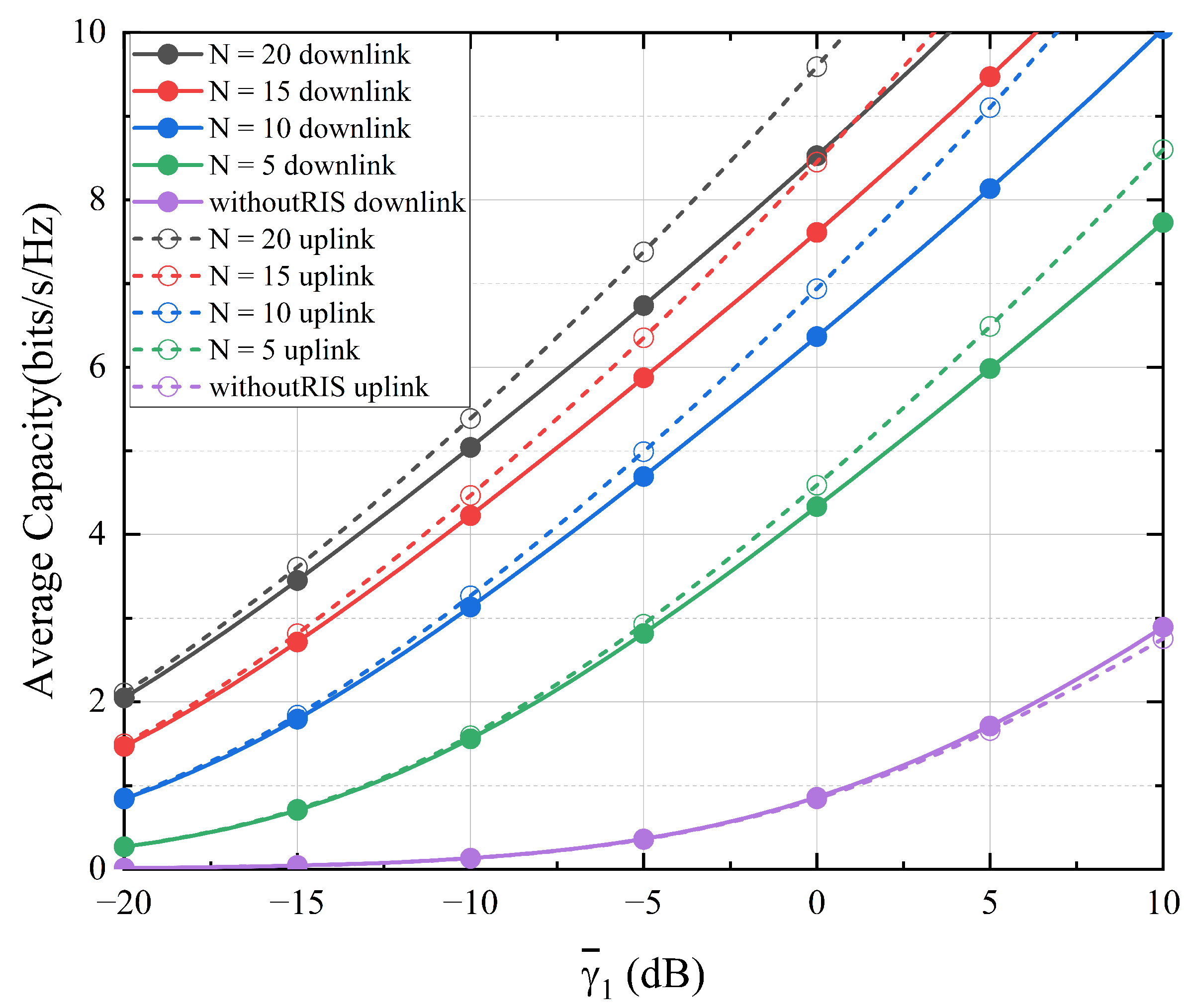
3.3. Average Channel Capacity

The accurate definition of the average channel capacity is given in [29,47], which is C ¯ = E log 2 ( 1 + γ ) . E ( · ) is the mathematical expectation operator. Based on this, the average channel capacity can be specifically expressed as [48,49]:
C = 0 log 2 ( 1 + γ ) f γ ( γ ) d γ = 1 ln 2 0 F γ C ( γ ) 1 + γ d γ ,
where F γ C ( γ ) = 1 F γ ( γ ) .

3.3.1. End-to-End Uplink

Substituting (11) into (22) and using the Fox’s H function [50], the average channel capacity of the end-to-end uplink is obtained as:
C u = 1 ln 2 0 1 1 + γ e γ B γ ¯ 1 m = 0 N 1 γ m ( B γ ¯ 1 ) m m ! 1 + W × G 5 , 1 2 , 6 α 1 α 2 β 1 β 2 A 0 γ γ ¯ 2 ϕ 1 ϕ 2 d γ = 1 ln 2 m = 0 N 1 1 ( B γ ¯ 1 ) m m ! G 2 , 1 1 , 2 1 B γ ¯ 1 m 0 , m + R × H   0 , 1 : 1 , 1 : 5 , 1 1 , 0 : 1 , 1 : 2 , 6 Λ ( 0 , 1 ) ( 0 , 1 ) Φ Ξ Δ , Θ ,
where H   m 1 , n 1 : m 2 , n 2 : m 3 , n 3 p 1 , q 1 : p 2 , q 2 : p 3 , q 3 · is the Fox’s H function, R = ξ 2 B γ ¯ 1 Γ ( α 1 ) Γ ( α 2 ) Γ ( β 1 ) Γ ( β 2 ) m ! ; Λ = ( m , 1 , 1 / 2 ) ; Φ = ( 1 , 1 ) , ( ξ 2 + 1 , 1 ) ; Ξ = ( ξ 2 , 1 ) , ( α 1 , 1 ) , ( α 2 , 1 ) , ( β 1 , 1 ) , ( β 2 , 1 ) , ( 0 , 1 ) ; Δ = B γ ¯ 1 ; Θ = α 1 α 2 β 1 β 2 A 0 B γ ¯ 1 γ ¯ 2 .

3.3.2. End-to-End Downlink

Similarly, by substituting (12) into (22), the average channel capacity of end-to-end downlink is written as:
C d = 1 ln 2 0 1 1 + γ e γ B γ ¯ 1 m = 0 N 1 γ m ( B γ ¯ 1 ) m m ! 1 + Q × G   3 , 1 2 , 4 α 3 β 3 γ γ ¯ 2 φ 1 φ 2 d γ = 1 ln 2 m = 0 N 1 1 ( B γ ¯ 1 ) m m ! G   2 , 1 1 , 2 1 B γ ¯ 1 m 0 , m + S × H 0 , 1 : 1 , 1 : 5 , 1 1 , 0 : 1 , 1 : 2 , 6 Λ ( 0 , 1 ) ( 0 , 1 ) Φ K Δ , Ω ,
where Q = ξ 2 Γ ( α 3 ) Γ ( β 3 ) ; S = ξ 2 B γ ¯ 1 Γ ( α 3 ) Γ ( β 3 ) m ; K = ( ξ 2 , 1 ) , ( α 3 , 1 ) , ( β 3 , 1 ) , ( 0 , 1 ) ; Ω = α 3 β 3 B γ ¯ 1 γ ¯ 2 .

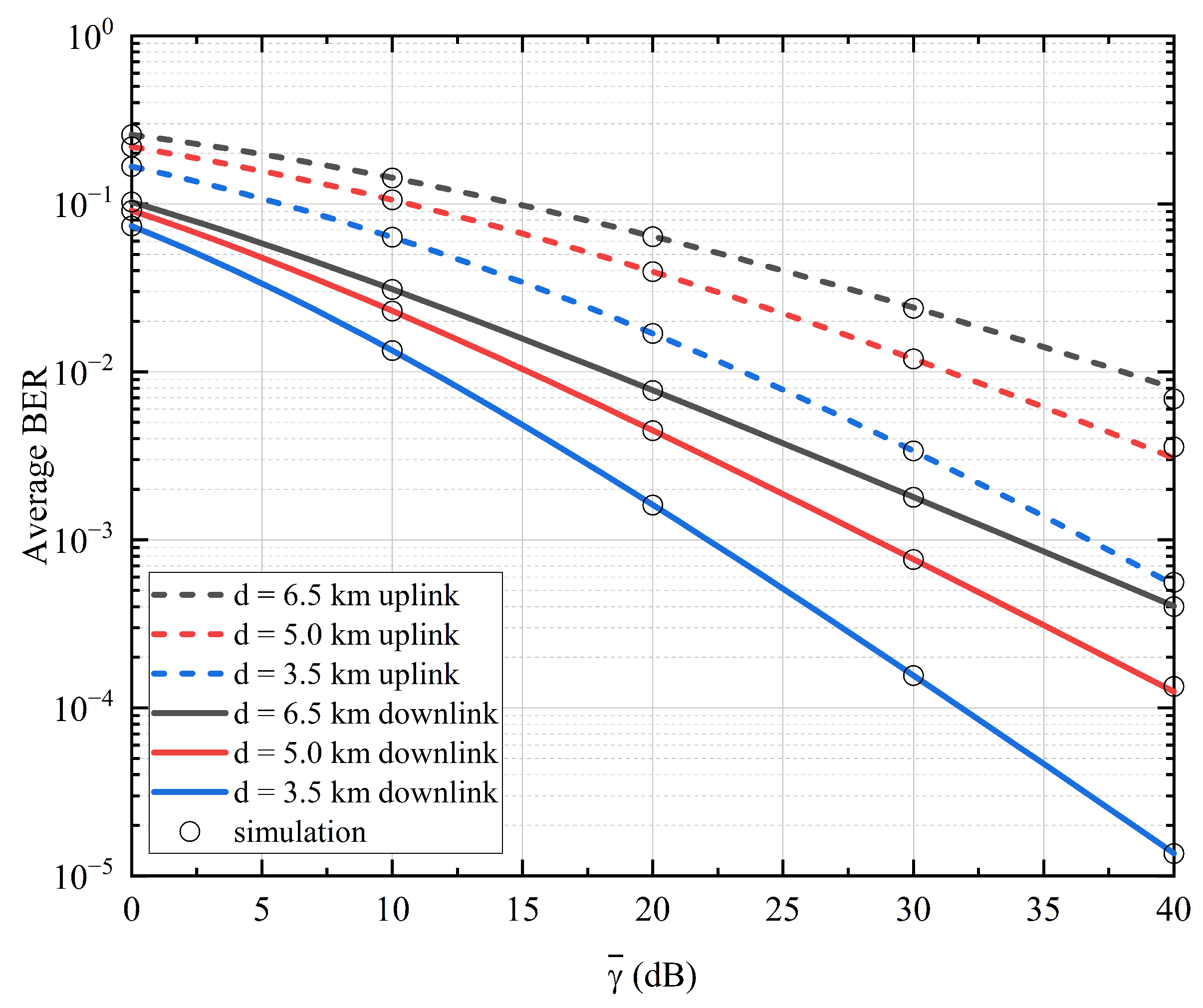
4. Numerical Results and Discussion

In this section, we utilize the mathematical expressions derived in Section 3 to evaluate the performance of the mixed RF/FSO UAV system based on MRR and RIS. Here, we do not consider factors such as the jitter of the UAV. In our analysis, the wavelength of the laser is set to 1550 nm, the aperture of both the MRR at the relay and the receiver at the destination is fixed at 10 cm, and the beamwidth at distance d is 0.03 m r a d d . In addition, the distance of the RF link is set to 1.0 km, and the FSO communication distance is generally 5.0 km without special instructions. The height of the optical receiver at the destination from the ground is 50 m, the height difference between the UAV and the optical receiver is 100 m, and the angle between the FSO link and the horizontal direction is 1.2 degrees. The number of iterations of the simulation is 10 6 . The atmospheric refractive index structure parameters are set to C n 2 = 5.2 × 10 16 m 2 / 3 ( α = 11.8 , β = 10.2 ), C n 2 = 6.5 × 10 15 m 2 / 3 ( α = 4.0 , β = 1.6 ), and C n 2 = 3.0 × 10 14 m 2 / 3 ( α = 6.0 , β = 1.1 ) corresponding to weak, moderate, and strong turbulence, respectively. Because of the use of MRR, the beam is immediately reflected from the UAV relay to the destination, we set α 1 = α 2 = α 3 = α and β 1 = β 2 = β 3 = β . For the pointing error, we let ξ = 10 as small pointing error and ξ = 1 as large pointing error.
The outage probability of the mixed RF/FSO UAV dual-hop system are shown in Figure 3, Figure 4 and Figure 5. In Figure 3, under moderate turbulence and small pointing error, we set N = 5 , 10 , 15 , 20 to analyze the impact of RIS on the outage probability of end-to-end downlink and end-to-end uplink by varying the number of reflective elements and compare the performance with that of the scheme without RIS. As expected, the outage probability with RIS is several orders of magnitude lower than the scheme without RIS. The simulation results show that the performance of the end-to-end downlink is better than that of the end-to-end uplink, which is caused by the fact that the FSO uplink experiences twice the atmospheric channel distance than the FSO downlink. In addition, both have their own performance thresholds, because we fixed the SNR of the FSO link, when the SNR is low, the performance of the whole system is greatly influenced by the RF link. Furthermore, when the SNR gradually increases, the outage probability of RF link will be very small and the performance of the whole system will be dominated by the FSO link. Specifically, when γ ¯ 1 = 5 dB and N = 10 , the end-to-end uplink and end-to-end downlink outage probabilities are 3.3 × 10 2 and 3.3 × 10 3 , respectively. Moreover, the outage probability decreases more significantly as N increases. Therefore, the use of RIS can improve system performance to a large extent by reducing outage probability, especially in low SNR regions.
In Figure 4a,b, the outage probability of end-to-end uplink and end-to-end downlink are analyzed under different atmospheric turbulence and pointing error. Here, we set γ ¯ 1 = γ ¯ 2 = γ ¯ . As clearly seen from the result, the outage probability of the uplink and downlink increases with the growth of atmospheric turbulence and pointing error. Furthermore, the downlink outperforms the uplink in the same weather conditions. For instance, under weak turbulence and small pointing error, the outage probability of uplink and downlink at γ ¯ = 20 dB are 8.1 × 10 3 and 8.6 × 10 6 , respectively. The reason for this phenomenon is that the atmospheric channel distance experienced by the FSO uplink is twice that of the FSO downlink.
Figure 5 analyzes the outage probability with different FSO communication distance under moderate turbulence and small pointing error, where d is set to 3.5 km, 5.0 km and 6.5 km. As expected, the result shows that the outage probability gradually drops as the FSO communication distance decreases. Likewise, the performance of the downlink still outperforms the uplink. Moreover, when γ ¯ = 30 dB, the outage probability of the uplink are 5.8 × 10 2 , 1.0 × 10 1 and 1.3 × 10 1 at 3.5 km, 5.0 km and 6.5 km, while they are 3.3 × 10 3 , 1.1 × 10 2 and 1.9 × 10 2 in the downlink.
Figure 6 illustrates the average BER performance of the end-to-end downlink using L-PPM-BPSK-SIM under conditions of moderate turbulence and small pointing error. Since many communication systems use BPSK modulation scheme with low BER to improve the communication performance, Figure 6 compares the L-PPM-BPSK-SIM and BPSK schemes. We set L = 4 , 8 , 16 , 32 , 64 , the data reveals that the average BER with L-PPM-BPSK-SIM less than that with the BPSK when the value of L is greater than eight, and the average BER decreases continuously as the value of L increases. For example, when γ ¯ = 30 dB, the average BER with the BPSK scheme is 2.7 × 10 3 , the average BER of the L-PPM-BPSK-SIM scheme reaches 1.6 × 10 3 , 7.7 × 10 4 and 3.9 × 10 4 for L of 16, 32 and 64, respectively.
Figure 7 depicts the average BER of end-to-end downlink and end-to-end uplink with different number of RIS reflective elements under moderate turbulence and small pointing error. Expectedly, the average BER performance of the downlink is significantly better than that of the uplink, and the average BER decreases to the threshold as the SNR increases, for reasons explained in Figure 3. Moreover, the larger the value of N, the faster the average BER decreases. Specifically, when γ ¯ 1 = 10 dB and N = 10 , the end-to-end uplink and downlink average BER is 3.1 × 10 3 and 1.3 × 10 4 . Obviously, the average BER performance with RIS has a great improvement over that the scheme without RIS.
Figure 8a,b demonstrate the average BER of the end-to-end uplink and end-to-end downlink under different atmospheric turbulence and pointing error. As expected, like the performance of outage probability, the average BER performance of the downlink is still better than that of the uplink. From Figure 8b, the average BER of weak turbulence is significantly smaller than that of moderate and strong turbulence. Moreover, when γ ¯ = 20 dB, the average BER of uplink and downlink under weak turbulence in Figure 8a are 2.2 × 10 2 and 1.5 × 10 2 , while in Figure 8b, the average BER of uplink and downlink are 1.7 × 10 5 and 4.6 × 10 8 .
In Figure 9, the average BER of different FSO communication distance is analyzed under moderate turbulence and small pointing error. Based on this, we set the FSO communication distance as 3.5 km, 5.0 km, and 6.5 km. Expectedly, the average BER of both the uplink and downlink reduces as d decreases. For instance, when γ ¯ = 30 dB, the average BER of the uplink are 3.4 × 10 3 , 1.2 × 10 2 and 2.4 × 10 2 at 3.5 km, 5.0 km and 6.5 km, while they are 1.6 × 10 4 , 7.7 × 10 4 and 1.8 × 10 3 in the downlink.
Finally in Figure 10, we illustrate the average channel capacity of the end-to-end uplink and end-to-end downlink by varying the number N of RIS reflective elements under moderate turbulence and small pointing error. It can be seen that the channel capacity of the uplink is slightly lower than that of the downlink when RIS is not available, while the channel capacity of the uplink is greater than that of the downlink with RIS. This proves that RIS has a greater improvement effect on the uplink than on the downlink. Furthermore, when γ ¯ 1 = 5 dB and N = 5 , the average channel capacity is 6.49 bits/s/Hz and 5.98 bits/s/Hz for the uplink and downlink, respectively, and 1.71 bits/s/Hz and 1.66 bits/s/Hz when RIS is not present. Furthermore, the performance improvement will be more pronounced as the value of N increases.

5. Conclusions

In this paper, we studied a mixed RF/FSO UAV system based on MRR and RIS with hybrid L-PPM-BPSK-SIM to improve the system performance. The RF channel and the FSO channel follow Rayleigh and Gamma–Gamma distributions, respectively. Note that atmospheric turbulence and pointing error were considered in the FSO link. Moreover, we derived closed expressions for the outage probability, average BER, and average channel capacity by using Meijer’s G function and Fox’s H function. Capitalizing on these expressions, we thoroughly evaluated the performance of the end-to-end uplink and end-to-end downlink, and analyzed the differences between them.
The study results show that the use of RIS can effectively improve the performance of the mixed RF/FSO UAV system, and the more the number of reflective elements of RIS is, the better the performance will be. However, the adoption of MRR is sacrificing uplink performance in exchange for the weight, size and power consumption reduction of the relay. As expected, this study not only addresses the limitation of UAV relay by installing MRR, but also significantly improve the overall performance of the system by adopting RIS. Moreover, using hybrid L-PPM-BPSK-SIM with an average symbol length L greater than eight can obviously improve the average BER of the system and outperform the BPSK scheme. Therefore, the work provides a meaningful reference for designing an optimal UAV-based communication system.

Author Contributions

Conceptualization, methodology, J.Y. and H.L.; software, validation, writing—original draft preparation, J.Y.; formal analysis, investigation, data curation, R.W., Z.W. and D.D.; writing—review and editing, visualization, X.W., M.J. and W.L.; supervision, project administration, funding acquisition, H.L. All authors have read and agreed to the published version of the manuscript.

Funding

This work was supported by National Natural Science Foundation of China (62175070, 61875057, 61774062); The Natural Science Foundation of Guangdong, China (2021A1515012652); and Science and Technology Program of Guangzhou (2019050001).

Institutional Review Board Statement

Not applicable.

Informed Consent Statement

Not applicable.

Data Availability Statement

Not applicable.

Conflicts of Interest

The authors declare no conflict of interest.

References

  1. Khalighi, M.A.; Uysal, M. Survey on free space optical communication: A communication theory perspective. IEEE Commun. Surv. Tutor. 2014, 16, 2231–2258. [Google Scholar] [CrossRef]
  2. Anbarasi, K.; Hemanth, C.; Sangeetha, R. A review on channel models in free space optical communication systems. Opt. Laser Technol. 2017, 97, 161–171. [Google Scholar] [CrossRef]
  3. Alzenad, M.; Shakir, M.Z.; Yanikomeroglu, H.; Alouini, M.S. FSO-Based Vertical Backhaul/Fronthaul Framework for 5G+ Wireless Networks. IEEE Commun. Mag. 2018, 56, 218–224. [Google Scholar] [CrossRef] [Green Version]
  4. Kaushal, H.; Kaddoum, G. Optical Communication in Space: Challenges and Mitigation Techniques. IEEE Commun. Surv. Tutor. 2017, 19, 57–96. [Google Scholar] [CrossRef] [Green Version]
  5. Lee, E.; Park, J.; Han, D.; Yoon, G. Performance analysis of the asymmetric dual-hop relay transmission with mixed RF/FSO links. IEEE Photonics Technol. Lett. 2011, 23, 1642–1644. [Google Scholar] [CrossRef]
  6. Kong, H.; Lin, M.; Zhu, W.P.; Amindavar, H.; Alouini, M.S. Multiuser scheduling for asymmetric FSO/RF links in satellite-UAV-terrestrial networks. IEEE Wirel. Commun. Lett. 2020, 9, 1235–1239. [Google Scholar] [CrossRef]
  7. Zeng, Y.; Zhang, R.; Lim, T.J. Wireless communications with unmanned aerial vehicles: Opportunities and challenges. IEEE Commun. Mag. 2016, 54, 36–42. [Google Scholar] [CrossRef] [Green Version]
  8. Goetz, P.G.; Rabinovich, W.S.; Mahon, R.; Murphy, J.L.; Ferraro, M.S.; Suite, M.R.; Smith, W.R.; Burris, H.R.; Moore, C.I.; Schultz, W.W.; et al. Modulating Retro-Reflector Lasercom Systems for Small Unmanned Vehicles. IEEE J. Sel. Areas Commun. 2012, 30, 986–992. [Google Scholar] [CrossRef]
  9. Achour, M. Free-space optical communication by retromodulation: Concept, technologies, and challenges. In Advanced Free-Space Optical Communications Techniques and Technologies; SPIE: Bellingham, WA, USA, 2004; Volume 5614, pp. 52–63. [Google Scholar] [CrossRef]
  10. Gilbreath, G.C.; Rabinovich, W.S.; Meehan, T.J.; Vilcheck, M.J.; Mahon, R.; Burris, R.; Stell, M.F.; Sokolsky, I.; Vasquez, J.A.; Bovais, C.S.; et al. Compact lightweight payload for covert datalink using a multiple quantum well modulating retroreflector on a small rotary-wing unmanned airborne vehicle. In Airborne Reconnaissance XXIV; SPIE: Bellingham, WA, USA, 2000; Volume 4127, pp. 57–67. [Google Scholar] [CrossRef] [Green Version]
  11. Junique, S.; Agren, D.; Wang, Q.; Almqvist, S.; Noharet, B.; Andersson, J.Y. A modulating retro-reflector for free-space optical communication. IEEE Photonics Technol. Lett. 2005, 18, 85–87. [Google Scholar] [CrossRef]
  12. Li, X.; Zhao, X.; Zhang, P. Bit error rate analysis for modulating retro-reflector free space optical communications with adaptive threshold over correlated Gamma Gamma fading channels. IEEE Commun. Lett. 2019, 23, 2275–2278. [Google Scholar] [CrossRef]
  13. Yang, G.; Li, C.; Li, J.; Geng, H.; Bi, M.; Fan, B.; Wang, T. Performance analysis of full duplex modulating retro-reflector free-space optical communications over single and double Gamma-Gamma fading channels. IEEE Trans. Commun. 2018, 66, 3597–3609. [Google Scholar] [CrossRef]
  14. El Saghir, B.M.; El Mashade, M.B.; Aboshosha, A.M. Performance analysis of modulating retro-reflector FSO communication systems over Málaga turbulence channels. Opt. Commun. 2020, 474, 126160. [Google Scholar] [CrossRef]
  15. Yang, G.; Li, Z.; Bi, M.; Zhou, X.; Zeng, R.; Wang, T.; Li, J. Channel modeling and performance analysis of modulating retroreflector FSO systems under weak turbulence conditions. IEEE Photonics J. 2017, 9, 1–10. [Google Scholar] [CrossRef]
  16. El Saghir, B.M.; El Mashade, M.B. Performance of Modulating Retro-Reflector FSO Communication Systems with Nonzero Boresight Pointing Error. IEEE Commun. Lett. 2021, 25, 1945–1948. [Google Scholar] [CrossRef]
  17. Di Renzo, M.; Zappone, A.; Debbah, M.; Alouini, M.S.; Yuen, C.; De Rosny, J.; Tretyakov, S. Smart radio environments empowered by reconfigurable intelligent surfaces: How it works, state of research, and the road ahead. IEEE J. Sel. Areas Commun. 2020, 38, 2450–2525. [Google Scholar] [CrossRef]
  18. Di Renzo, M.; Ntontin, K.; Song, J.; Danufane, F.H.; Qian, X.; Lazarakis, F.; De Rosny, J.; Phan-Huy, D.T.; Simeone, O.; Zhang, R.; et al. Reconfigurable intelligent surfaces vs. relaying: Differences, similarities, and performance comparison. IEEE Open J. Commun. Soc. 2020, 1, 798–807. [Google Scholar] [CrossRef]
  19. Yang, L.; Guo, W.; Ansari, I.S. Mixed dual-hop FSO-RF communication systems through reconfigurable intelligent surface. IEEE Commun. Lett. 2020, 24, 1558–1562. [Google Scholar] [CrossRef]
  20. Yang, L.; Meng, F.; Zhang, J.; Hasna, M.O.; Di Renzo, M. On the performance of RIS-assisted dual-hop UAV communication systems. IEEE Trans. Veh. Technol. 2020, 69, 10385–10390. [Google Scholar] [CrossRef]
  21. Basar, E.; Di Renzo, M.; De Rosny, J.; Debbah, M.; Alouini, M.S.; Zhang, R. Wireless communications through reconfigurable intelligent surfaces. IEEE Access 2019, 7, 116753–116773. [Google Scholar] [CrossRef]
  22. Salhab, A.M.; Yang, L. Mixed RF/FSO Relay Networks: RIS-Equipped RF Source vs RIS-Aided RF Source. IEEE Wirel. Commun. Lett. 2021, 10, 1712–1716. [Google Scholar] [CrossRef]
  23. Cai, Y.; Qin, Z.; Cui, F.; Li, G.Y.; McCann, J.A. Modulation and multiple access for 5G networks. IEEE Commun. Surv. Tutor. 2017, 20, 629–646. [Google Scholar] [CrossRef] [Green Version]
  24. Khallaf, H.S.; Shalaby, H.M.; Garrido-Balsells, J.M.; Sampei, S. Performance analysis of a hybrid QAM-MPPM technique over turbulence-free and Gamma–Gamma free-space optical channels. J. Opt. Commun. Netw. 2017, 9, 161–171. [Google Scholar] [CrossRef]
  25. Faridzadeh, M.; Gholami, A.; Ghassemlooy, Z.; Rajbhandari, S. Hybrid pulse position modulation and binary phase shift keying subcarrier intensity modulation for free space optics in a weak and saturated turbulence channel. JOSA A 2012, 29, 1680–1685. [Google Scholar] [CrossRef] [Green Version]
  26. Giri, R.K.; Patnaik, B. Bit error rate performance analysis of hybrid subcarrier intensity modulation-based FSO with spatial diversity in various weather conditions. J. Opt. Commun. 2019, 40, 307–314. [Google Scholar] [CrossRef]
  27. Giri, R.K.; Patnaik, B. BER analysis and capacity evaluation of FSO system using hybrid subcarrier intensity modulation with receiver spatial diversity over Log-normal and Gamma–Gamma channel model. Opt. Quantum Electron. 2018, 50, 231. [Google Scholar] [CrossRef]
  28. Xu, G. BER and channel capacity of a deep space FSO communication system using L-PPM-MSK-SIM scheme during superior solar conjunction. Opt. Express 2019, 27, 24610–24623. [Google Scholar] [CrossRef]
  29. Park, J.; Lee, E.; Park, G.; Roh, B.; Yoon, G. Performance analysis of asymmetric RF/FSO dual-hop relaying systems for UAV applications. In Proceedings of the MILCOM 2013—2013 IEEE Military Communications Conference, San Diego, CA, USA, 18–20 November 2013; pp. 1651–1656. [Google Scholar] [CrossRef]
  30. Bayaki, E.; Schober, R.; Mallik, R.K. Performance analysis of MIMO free-space optical systems in gamma-gamma fading. IEEE Trans. Commun. 2009, 57, 3415–3424. [Google Scholar] [CrossRef]
  31. Yang, L.; Meng, F.; Wu, Q.; da Costa, D.B.; Alouini, M.S. Accurate closed-form approximations to channel distributions of RIS-aided wireless systems. IEEE Wirel. Commun. Lett. 2020, 9, 1985–1989. [Google Scholar] [CrossRef]
  32. El Saghir, B.M.; El Mashade, M.B.; Aboshosha, A.M. Performance analysis of MRR FSO communication system under Gamma–Gamma turbulence channel with pointing error. Opt. Commun. 2021, 489, 126891. [Google Scholar] [CrossRef]
  33. AlQuwaiee, H.; Yang, H.C.; Alouini, M.S. On the asymptotic capacity of dual-aperture FSO systems with generalized pointing error model. IEEE Trans. Wirel. Commun. 2016, 15, 6502–6512. [Google Scholar] [CrossRef] [Green Version]
  34. Al-Eryani, Y.F.; Salhab, A.M.; Zummo, S.A.; Alouini, M.S. Two-way multiuser mixed RF/FSO relaying: Performance analysis and power allocation. J. Opt. Commun. Netw. 2018, 10, 396–408. [Google Scholar] [CrossRef]
  35. Zedini, E.; Soury, H.; Alouini, M.S. On the performance analysis of dual-hop mixed FSO/RF systems. IEEE Trans. Wirel. Commun. 2016, 15, 3679–3689. [Google Scholar] [CrossRef] [Green Version]
  36. Miridakis, N.I.; Matthaiou, M.; Karagiannidis, G.K. Multiuser relaying over mixed RF/FSO links. IEEE Trans. Commun. 2014, 62, 1634–1645. [Google Scholar] [CrossRef] [Green Version]
  37. Anees, S.; Bhatnagar, M.R. Information theoretic analysis of DF based dual-hop mixed RF-FSO communication systems. In Proceedings of the 2015 IEEE 26th Annual International Symposium on Personal, Indoor, and Mobile Radio Communications (PIMRC), Hong Kong, China, 30 August–2 September 2015; pp. 600–605. [Google Scholar] [CrossRef]
  38. Zhang, Y.; Wang, X.; Zhao, S.h.; Zhao, J.; Deng, B.y. On the performance of 2× 2 DF relay mixed RF/FSO airborne system over Exponentiated Weibull fading channel. Opt. Commun. 2018, 425, 190–195. [Google Scholar] [CrossRef]
  39. Bag, B.; Das, A.; Bose, C.; Chandra, A. Improving the performance of a DF relay-aided FSO system with an additional source–relay mmWave RF backup. J. Opt. Commun. Netw. 2020, 12, 390–402. [Google Scholar] [CrossRef]
  40. Yu, S.; Ding, J.; Fu, Y.; Ma, J.; Tan, L.; Wang, L. Novel approximate and asymptotic expressions of the outage probability and BER in Gamma-Gamma fading FSO links with generalized pointing errors. Opt. Commun. 2019, 435, 289–296. [Google Scholar] [CrossRef]
  41. Jin, M.; Liu, W.; Hao, Y.; Wu, R.; Wei, Z.; Deng, D.; Liu, H. Hybrid Dual-Hop RF/FSO Terrestrial-Deep Space Communication System under Solar Scintillation during Superior Solar Conjunction. Appl. Sci. 2022, 12, 619. [Google Scholar] [CrossRef]
  42. Faridzadeh, M.; Gholami, A.; Ghassemlooy, Z.; Rajbhandari, S. Hybrid 2-PPM-BPSK-SIM with the spatial diversity for free space optical communications. In Proceedings of the 2012 8th International Symposium on Communication Systems, Networks & Digital Signal Processing (CSNDSP), Poznan, Poland, 18–20 July 2012; pp. 1–5. [Google Scholar] [CrossRef]
  43. Elganimi, T.Y. Performance comparison between OOK, PPM and PAM modulation schemes for free space optical (FSO) communication systems: Analytical study. Int. J. Comput. Appl. 2013, 79. [Google Scholar] [CrossRef]
  44. Al-Ebraheemy, O.M.S.; Salhab, A.M.; Chaaban, A.; Zummo, S.A.; Alouini, M.S. Precise performance analysis of dual-hop mixed RF/unified-FSO DF relaying with heterodyne detection and two IM-DD channel models. IEEE Photonics J. 2019, 11, 1–22. [Google Scholar] [CrossRef]
  45. Gradshteyn, I.S.; Ryzhik, I.M. Table of Integrals, Series, and Products; Academic Press: Cambridge, MA, USA, 2014. [Google Scholar] [CrossRef]
  46. Ansari, I.S.; Al-Ahmadi, S.; Yilmaz, F.; Alouini, M.S.; Yanikomeroglu, H. A new formula for the BER of binary modulations with dual-branch selection over generalized-K composite fading channels. IEEE Trans. Commun. 2011, 59, 2654–2658. [Google Scholar] [CrossRef] [Green Version]
  47. Ashrafzadeh, B.; Zaimbashi, A.; Soleimani-Nasab, E. A framework on the performance analysis of relay-assisted FSO transmission systems. Opt. Commun. 2019, 450, 352–365. [Google Scholar] [CrossRef]
  48. Aggarwal, M.; Garg, P.; Puri, P. Dual-hop optical wireless relaying over turbulence channels with pointing error impairments. J. Light. Technol. 2014, 32, 1821–1828. [Google Scholar] [CrossRef]
  49. Peppas, K.P.; Stassinakis, A.N.; Topalis, G.K.; Nistazakis, H.E.; Tombras, G.S. Average capacity of optical wireless communication systems over IK atmospheric turbulence channels. J. Opt. Commun. Netw. 2012, 4, 1026–1032. [Google Scholar] [CrossRef]
  50. Mittal, P.; Gupta, K. An integral involving generalized function of two variables. Proc. Indian Acad. Sci.-Sect. A 1972, 75, 117–123. [Google Scholar] [CrossRef]
Figure 1. A mixed RF/FSO UAV communication system based on MRR and RIS.
Photonics 09 00379 g001
Figure 2. Schematic diagram of MRR FSO with bidirectional communication.
Photonics 09 00379 g002
Figure 3. Outage probability with different N when γ t h = 15 dB, α = 4.0 , β = 1.6 , ξ = 10 , γ ¯ 2 = 50 dB, d = 5.0 km.
Photonics 09 00379 g003
Figure 4. Outage probability under different atmospheric turbulence and pointing error when γ t h = 0 dB, ξ = 10 , N = 10 , d = 5.0 km.
Photonics 09 00379 g004
Figure 5. Outage probability under different FSO communication distance when γ t h = 0 dB, ξ = 10 , N = 10 .
Photonics 09 00379 g005
Figure 6. Average BER of end-to-end downlink under different L when α = 4.0 , β = 1.6 , ξ = 10 , d = 5.0 km, N = 10 .
Photonics 09 00379 g006
Figure 7. Average BER with different N when α = 4.0 , β = 1.6 , ξ = 10 , γ ¯ 2 = 40 dB, d = 5.0 km, L = 32 .
Photonics 09 00379 g007
Figure 8. Average BER under different pointing error and atmospheric turbulence when d = 5.0 km, L = 32 , N = 10 .
Photonics 09 00379 g008
Figure 9. Average BER under different FSO communication distance when ξ = 10 , L = 32 , N = 10 .
Photonics 09 00379 g009
Figure 10. Average channel capacity under different N when α = 4.0 , β = 1.6 , ξ = 10 , γ ¯ 2 = 40 dB, d = 5.0 km.
Photonics 09 00379 g010
Publisher’s Note: MDPI stays neutral with regard to jurisdictional claims in published maps and institutional affiliations.

