Article

Spatial Three-Mirror Off-Axis Freeform Optical System without Any Symmetry

State Key Laboratory of Precision Measurement Technology and Instruments, Department of Precision Instrument, Tsinghua University, Beijing 100084, China
*
Author to whom correspondence should be addressed.
Photonics 2022, 9(5), 326; https://doi.org/10.3390/photonics9050326
Submission received: 10 April 2022 / Revised: 7 May 2022 / Accepted: 7 May 2022 / Published: 9 May 2022
(This article belongs to the Special Issue Freeform Optics)

Abstract

:
In this manuscript, we have launched a study on the completely nonsymmetric freeform optical system with neither rotational symmetry nor planar symmetry. An off-axis three-mirror freeform optical system with nonsymmetric geometry is proposed and a direct design method is developed for the nonsymmetric freeform optical system. The design field points are sampled across the full FOV to control the imaging quality and object–image relationship. In this system, the center of the image plane is greatly away from the plane determined by the centers of the three mirrors. This nonsymmetric system with F/1.3, a focal length of 50 mm, and an 8° × 6° field of view can achieve imaging quality close to the diffraction limit. This work provides a feasible nonsymmetric system design idea for the optical community.

1. Introduction

Coaxial optical systems and off-axis planar symmetric optical systems are the main objectives in optical design, and mature design theories are available for these systems. The opposite of the two system types described above is an optical system without any symmetry. Such a system has neither a rotational symmetry axis nor a planar symmetry plane and is called a nonsymmetric optical system.
Nonsymmetric systems inherently have a lower degree of symmetry and high design freedom. The surface position of a nonsymmetric system is relatively more flexible, which makes it possible to design optical systems with exotic structures. The design of a nonsymmetric optical system is challenging, particularly when the purpose of a nonsymmetric system is to realize a system with a specific structure and high imaging performance. Removal of the symmetry of the optical system will introduce additional aberrations [1,2,3,4,5,6]. In [2,3], the general case of optical systems without symmetry is extended from paraxial optics, and the aberrations, in this case, are described. The nodal aberration theory [4,5], which discusses the aberrations of optics without symmetry and including freeform surfaces, is an aberration theory that can be used to guide the design of nonsymmetric optical systems. In [6], the nonsymmetric systems are studied based on phase space aberration theory. Therefore, there will be nonsymmetrical aberrations in a nonsymmetric system. Correction of these nonsymmetrical aberrations is an important issue that must be solved during the design of such systems. Designing nonsymmetric freeform optical systems is therefore both interesting and challenging.
The optical freeform surface is generally defined as a surface whose shape lacks rotational symmetry, and this type of surface has numerous degrees of freedom [7,8]. In recent years, benefiting from the ongoing developments in freeform surface design, processing, assembly, and test technology, freeform surfaces have become a research hotspot in the optics field and are widely used in the optical community [7,8,9,10,11,12,13,14,15,16,17,18]. Due to the high flexibility of the freeform surfaces, they can be used to correct nonsymmetrical aberrations, which thus makes nonsymmetric systems technically possible.
Several freeform surface design methods have been developed to date: traditional design methods based on multi-parameter optimization, design methods based on aberration theory [19,20,21,22], and direct design methods [9,10,23,24,25,26,27,28,29,30]. They have been widely used in the design of optical systems with planar symmetry. In addition, there are a few studies on design methods [6,31] applicable for optical systems without any symmetry. In [6], a shark tooth freeform prism absolutely without symmetry for a head-mounted display is designed using the phase space aberration theory. It often starts from a system with symmetry and then adjusts the position and inclination of the optical surface to obtain an unobscured nonsymmetric system. The authors of [31] describe a design method for an optical system described in a vector space based on Fermat’s principle and Snell’s law, as well as an optimization method to minimize the lens’ aberrations. Additionally, this method places no restrictions on the symmetry of the design system. The system containing two surfaces was designed using this method.
In this manuscript, a nonsymmetric freeform optical system direct design method is developed to realize the desired system. Using our method, we can construct a freeform system directly from a planar initial system without careful selection of a suitable initial solution. The structure of the planar initial system can be flexibly arranged according to the system geometry, volume, and other requirements. In the design process, the point-by-point method is used to control the propagation path of light rays. The design field points are sampled across the full field of view (FOV) to control the imaging quality and the object–image relationship. In the intermediate process, the designer does not need to use the aberration theory to perform aberration correction. The design method in this paper can obtain a good starting point of the nonsymmetric system in a few minutes, which can be simply optimized to get a usable optical system
A nonsymmetric off-axis three-mirror freeform optical system is proposed to illustrate the effectiveness of the proposed method. The system operates at F/1.3 with an 8° × 6°FOV and has a 38.5 mm entrance pupil diameter. The system is intended to operate close to the diffraction limit in the long-wave infrared (LWIR) range. The normal vector at the center of each surface in the system and the normal vector of the image plane are not located in the same plane, and the centers of these four surfaces are also not in the same plane. In this system, there is an angle of 45° between the normal direction of the image plane and the YZ plane, which is beneficial for the application in special scenarios that have clear requirements for the shape of the system. In addition, the size of the system in the XYZ dimensions is similar at approximately 140, 150, and 140 mm, respectively.

2. Nonsymmetric Off-Axis Three-Mirror System Design

2.1. Structure and Performance Parameters

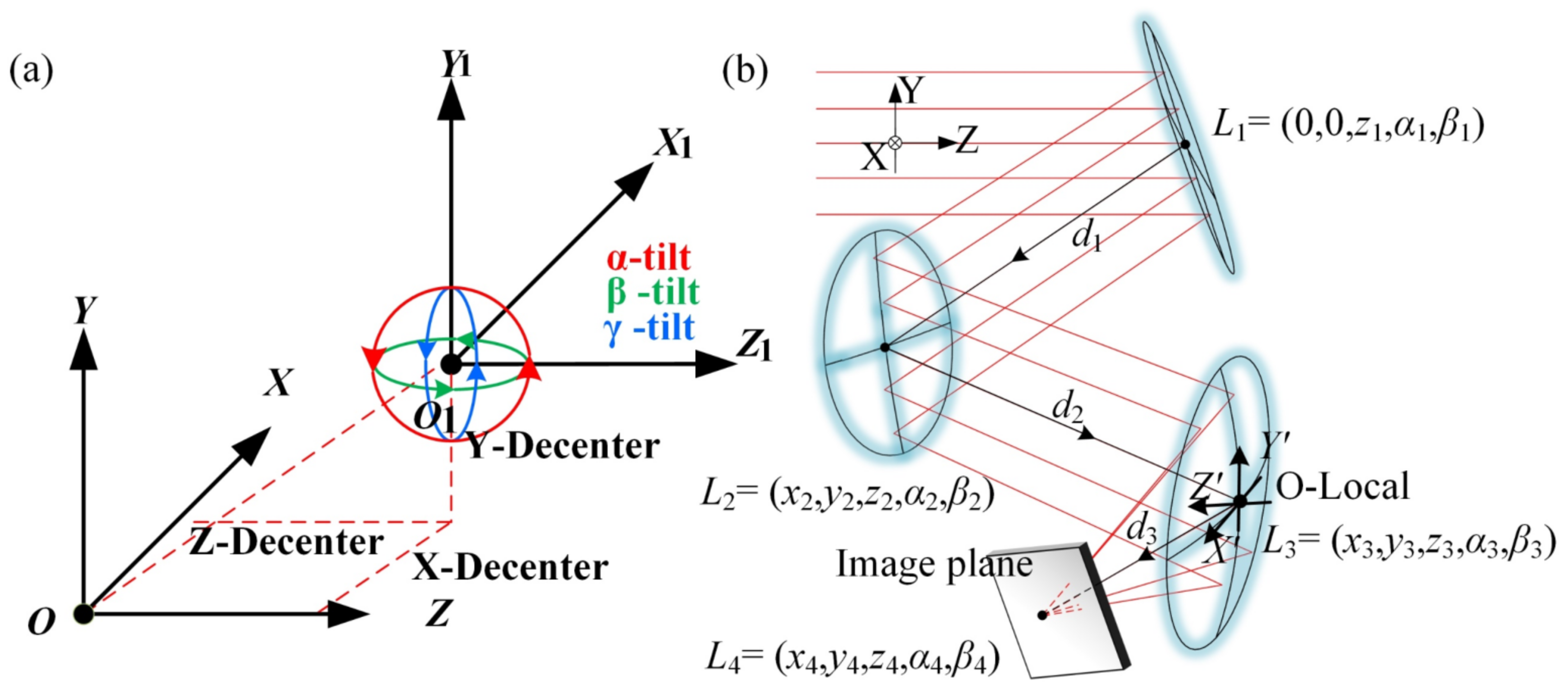
In an off-axis system, the decenters and tilts of the local coordinate system of a surface relative to the global coordinate system can be used to describe the positional properties of that surface. The local coordinate system is generally defined with a local coordinate system origin at the center of the surface. Here, the center of a surface is defined as the vertex of its best-fit conic surface. The coordinate system for a surface can be shifted in the X, Y, and Z dimensions and tilted in the YZ, XZ, and XY planes relative to the coordinate system of the previous surface [32]. These shifts and tilts are illustrated in Figure 1a. When the coordinate system of the previous surface is the global coordinate system, these shifts and tilts are the X, Y, and Z decenters, and α, β, and γ tilts are used to describe the position of the surface local coordinate system, in which the definitions of α, β, and γ tilts are the same as those of tilt, pitching, and deflection in the mechanical field, which is conducive to the coordination of design and manufacture. Additionally, the coordinate system for the nonsymmetric systems is consistent with the definition of the optical surface coordinate system in CODEV, which is convenient for the further optimization of the starting point obtained by the proposed nonsymmetric design method.
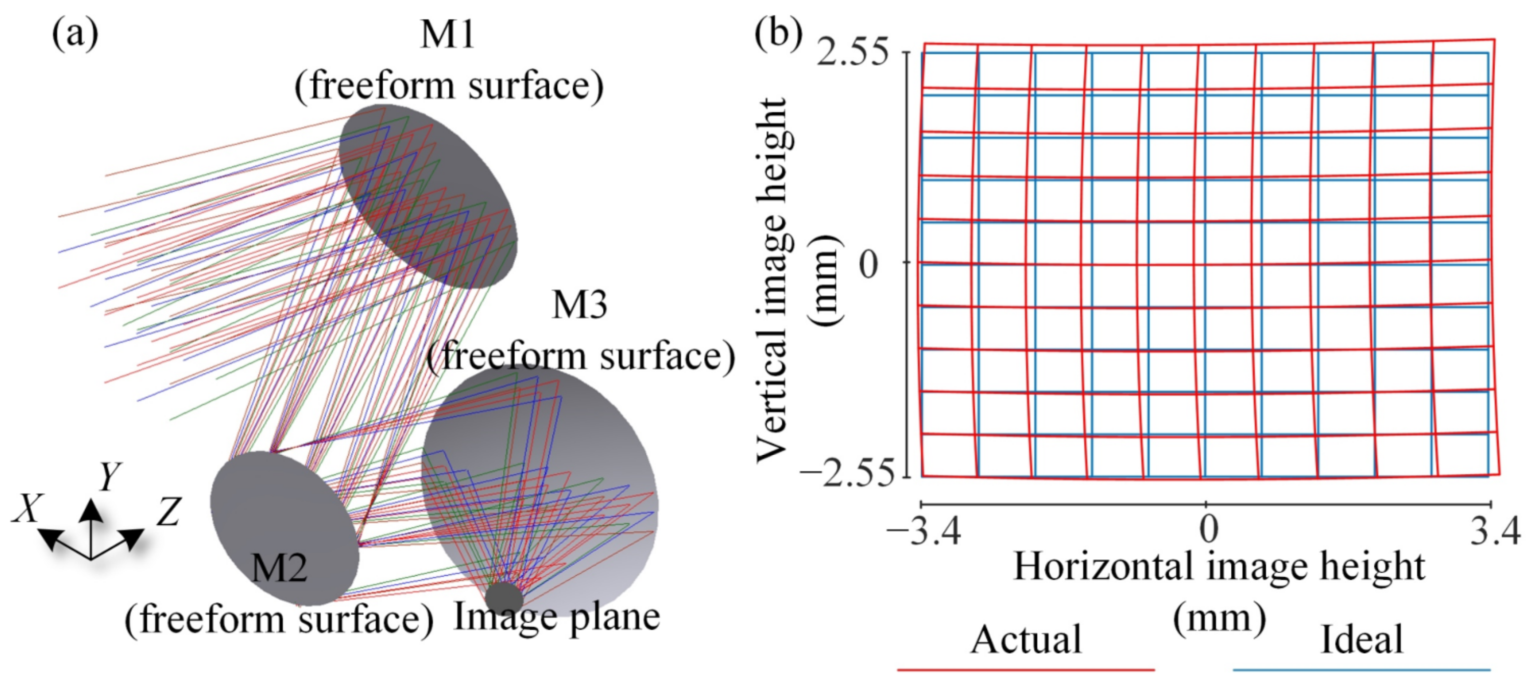
We can therefore introduce the structure of the nonsymmetric system based on this type of description. The global coordinate system of the proposed optical system can be established, and the Z axis of the global coordinate system coincides with the chief ray of the central field in the object space. Figure 1b shows the global coordinate system of the nonsymmetric off-axis three-mirror freeform system and the local coordinate system of one surface.
In the defined coordinate system, a nonsymmetric system can be defined as an optical system in which the chief ray of the central field can be deflected out of the YZ plane after reflection/refraction from the surfaces within the system. Each surface in this optical system can have α, β, and γ tilts relative to the global coordinate system. In addition, except for the center of the primary mirror, which is located near the YZ plane, the centers of the other surfaces are all located outside the YZ plane. This means that each surface in the system can be decentered in the X, Y, and Z dimensions relative to the global coordinate system. Like other optical systems, the light rays in a nonsymmetric system will eventually converge on the image plane to realize the required imaging. Since the chief ray of the central field in the image space is deflected outside the YZ plane, the center of the image plane is also located outside the YZ plane and the image plane can have three decenters and three tilts relative to the global coordinate system. In addition, Figure 1b shows that the normal vector at the center of each surface in the system and the normal vector of the image plane are not located in the same plane, and the centers of the four surfaces are also not in the same plane.
In a coaxial optical system, the Z decenter can describe the position of the surfaces. The centers of the system’s surfaces can only be located on the Z axis, and these surfaces are not tilted. In an off-axis optical system with planar symmetry, the Y decenter, Z decenter, and α tilt can describe the positions of the surfaces. The centers of these surfaces are located in the YZ plane, and each surface has only one tilt. In a nonsymmetric system, however, the centers of the surfaces and the center of the image plane can be placed in any position and can also have any tilt relative to the coordinate system. When compared with the previous two system types, the structure of a nonsymmetric system is both more complex and more flexible.

2.2. Design Method

In this manuscript, a direct design method for nonsymmetric freeform systems is developed to realize the proposed nonsymmetric freeform system. First, an initial plane system is established. Then, the point-by-point method is used to calculate the coordinates and the normal vectors of a series of data points and fit them to freeform surfaces to obtain an initial solution. Finally, the initial solution obtained in the previous step is used as the starting point for design optimization to improve the imaging quality.

2.3. Establish the Nonsymmetric Initial Plane System

The structure of the initial plane system is consistent with the initial solution calculated by the point-by-point method. This feature is the key to designing the nonsymmetric structure. Therefore, first, establish an initial plane system that is consistent with the expected system structure, but without optical power.
When designing the planar symmetry system, there were structures for reference or suitable construction methods. In the worst case, it can be constructed by patchwork. However, the spatial position of each surface of a nonsymmetric system has high degrees of flexibility, and its structural forms are also diverse. Therefore, it is difficult to piece together the initial plane structure with the imagination of the designer. Besides, there are few nonsymmetric system structures for reference. To ensure that the initial system calculated by the point-by-point method can obtain a convergence result, it is necessary to discuss the parameters that determine the structure of the nonsymmetric system.
According to the discussion in Section 2.1, when the position parameters of each surface are determined, the structure of the system is determined, as shown in Figure 1b. The vector Li = (xi,yi,zi,αi,βi) (i = 1,2,3…M, where M is the number of surfaces including the image plane, for three mirrors system, M = 4) can be used to describe the position parameters of the ith surface. Next, determine the position vector of each surface in the system. In this work, a nonsymmetric initial plane system is constructed based on the following principles: (1) The offset of the FOV and aperture is not considered, (2) the chief ray of the central field passes through the origin of the global coordinate system, and its direction vector is (0,0,1), and (3) the chief ray of the central field passes through the center of each surface. (4) The position of the image plane has been provided under the actual requirements and the estimation of the system size, that is, L4 is fixed. (5) The chief ray of the central field is incident perpendicular to the image plane.
According to the principles, we can calculate the direction vector of the chief ray of the central field after being reflected by the tertiary mirror and determine the position vector of the primary mirror, which is L1 = (0,0,z1,α1,β1). Besides, the relative position of the image plane and the primary mirror determines the volume of the system, so the z1 coordinate of the primary mirror can be obtained according to the requirements of the system volume and the position of the image plane. At this time, α1 and β1 are still unknown, so we assume that they are at a certain angle. Next, the direction vector of the chief ray of the central field after being reflected by the primary mirror can be calculated according to the law of reflection. If the distance d1 from the primary mirror to the secondary mirror is provided, the center of the secondary mirror (x2,y2,z2) can be obtained by a simple geometric relationship. In the same way, if the distance d3 from the tertiary mirror to the image plane is provided, the center of the tertiary mirror (x3,y3,z3) can be obtained. Next, according to principle (3), the direction vector of the outgoing ray of the chief ray of the central field on the secondary mirror can be calculated, which is also the incident ray of the chief ray of the central field on the tertiary mirror. Finally, the normal vectors of the secondary mirror and the tertiary mirror can be calculated based on the reflection law, also obtaining α2, β2 and α3, β3. From the above discussion, it can be found that L2 and L3 are uniquely determined by α1, β1, d1, and d3, so the structure of the system is uniquely determined by α1, β1, d1, and d3. Then, we can provide a series of α1, β1, d1, and d3, and select a group from them to establish the nonsymmetric initial plane system. The selection criteria are: the rotation angle of each surface is close, the surface distance is appropriate, and the size in the XYZ dimensions is close.

2.4. Obtaining the Starting Point for Optimization

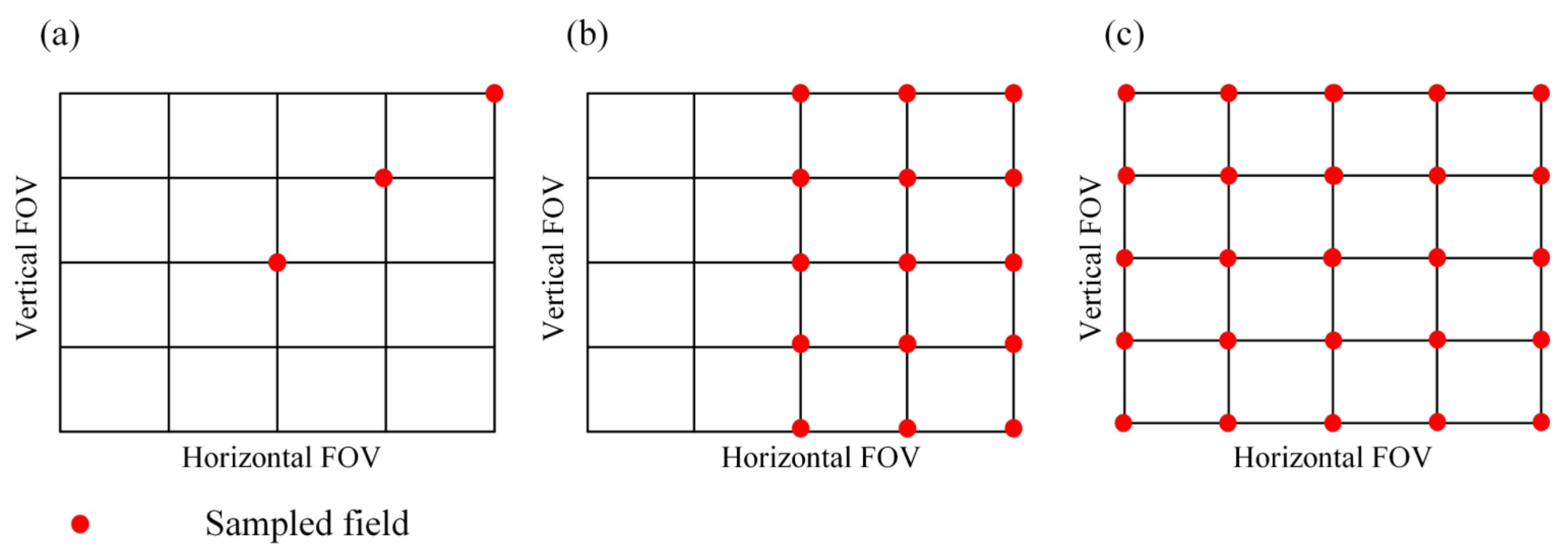
Before the calculations can be performed, the feature light rays as well as the starting and target points of the feature light rays must be defined. The feature light rays are the sample rays used for the calculation and are sampled from multiple field angles and using different pupil coordinates. When designing a system with rotational symmetry, it is only necessary to sample the FOV along a radial direction. For a planar symmetric system, only half of the system’s full FOV needs to be sampled. However, the nonsymmetric system proposed in this manuscript does not have such symmetry and thus needs to be sampled across the full FOV, which means that designing such systems is more challenging. Figure 2 shows the sampling fields for these three system types.
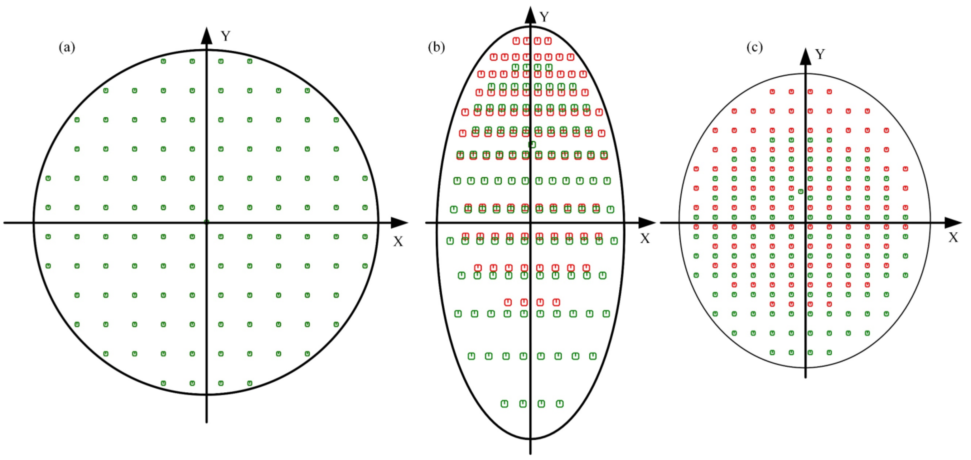
Then, we can choose polar grids or rectangular grids to uniformly sample the rays of different pupil positions. When the ray beam is incident on the surface obliquely, although the feature light rays are uniform on the pupil, the distribution of the intersection points of the feature light rays on the surface is usually uneven, and the unevenness of the feature light rays from different fields is also inconsistent, as shown in Figure 3.
The feature data points calculated by using uneven feature light rays cannot obtain the best fitting result. In a nonsymmetric system, it is even worse. One solution is to increase the number of feature rays, but as the number of rays increases, the number of calculations will increase. In this work, we propose an effective solution. There can be a different number of sampled rays for different fields and different surfaces. Taking polar grids as an example, for a certain surface, for a certain field, a series of polar angles can be evenly divided on the pupil. Different numbers of rays can be sampled at different polar angles, and the number of rays is determined by the footprint map on the surface. Through real ray tracing, the coordinates of the intersection of the chief ray and the edge ray on the surface can be obtained, and then the distance, d(α), between the intersection of the chief ray and the intersection of the edge ray can be calculated, where α is a polar angle. If the distance corresponding to the sampling polar angle is short, the number of sampled rays is small, and vice versa. The number, N(α), of sampled rays in sample polar angle α is,
N ( α ) = d ( α ) min ( d ( α ) ) · N ,
where N is the number of sampled rays corresponding to the polar angle with the shortest distance.
Next, we must determine the starting and target points of the feature light rays, where the starting points can be the intersections of the feature rays with any virtual surface located before the first surface of the system (this virtual surface can then be the YZ plane of the global coordinate system) and the target points are the ideal image points. The image heights on the image plane are then obtained according to the given object–image relationship, i.e., the coordinates of the ideal image points are obtained in the local coordinate system of the image plane. However, the point-by-point method was performed within the global coordinate system, while the image plane of the nonsymmetric system is both decentered and tilted relative to the global coordinate system. Therefore, the coordinates of the image points in the local coordinate system of the image plane must be converted into the corresponding coordinates in the global coordinate system. When the image plane position is determined, the coordinates of the ideal image points in the global coordinate system can then be calculated based on the specified object–image relationship obtained by Equations (2) and (3):
T = cos ( γ i ) sin ( γ i ) 0 sin ( γ i ) cos ( γ i ) 0 0 0 1 × cos ( β i ) 0 sin ( β i ) 0 1 0 sin ( β i ) 0 cos ( β i ) × 1 0 0 0 cos ( α i ) sin ( α i ) 0 sin ( α i ) cos ( α i ) ,
H n = T × f tan ω n , x f tan ω n , y 0 + x i y i z i ,
Here, T is the rotation transformation matrix from the local coordinate system to the global coordinate system, and xI, yI, and zI and αI, βI, and γI are the decenters and tilts of the image plane relative to the global coordinate system, respectively. f is the focal length of the system, ωn,x and ωn,y are the nth field angles in the X and Y dimensions, respectively, and Hn represents the coordinates of the ideal image points of the nth feature field angles in the global coordinate system.
Next, we can perform the point-by-point calculation process [9,10,29] to construct the freeform surfaces. To better understand this, here, we briefly introduce the data calculation process. During the construction process, a Nearest-Ray algorithm [29] is used to determine the order of calculating data points and their coordinates. Then, we calculate the normal vectors of these data points based on Fermat’s principle and Snell’s law. These data points can then be used to perform the surface fitting. Surface fitting refers to the fitting of the surface shape and acquiring the position of the surface. The general form of a mathematical expression for a freeform surface involves the addition of freeform terms on the basis of a conic surface, as shown in Equation (4):
z ( x , y ) = c ( x 2 + y 2 ) 1 + 1 ( 1 + k ) c 2 ( x 2 + y 2 ) + i N A i g i ( x , y ) ,
where c is the curvature of the surface, k is the conic coefficient, Ai is the coefficient of the ith freeform term, and gi(x,y) is the freeform surface term described using polynomials such as Zernike polynomials or XY polynomials. In the work introduced here, we use the XY polynomials with the highest order of six. Therefore, the freeform surface terms can be provided by Equation (5):
i N A i g i ( x , y ) = m = 0 6 n = 0 6 a m , n x m y n   ,   1 < m + n 6 ,
The freeform surface of the planar symmetric system only needs to be described using the even-order terms of x in the XY polynomial, but the surface of the nonsymmetric system must be described using all the terms in the first N orders. According to Equations (4) and (5), when N = 6, the number of surface parameters used to describe the planar symmetric freeform surface is 15, while the number required for the nonsymmetric freeform surface is 27. This indicates that the surface of the nonsymmetric system has greater flexibility and is more conducive to the realization of high-performance and special applications. Greater freedom also means greater design difficulty, and designing such a system is a challenge.
Generally, the freeform surface shape is a function of the surface sag, which varies with the coordinates in the surface local coordinate system, such as those provided by Equations (4) and (5), and this function should thus be fitted into the local coordinate system. However, the calculation process for the data points is performed in the global coordinate system. Therefore, it is first necessary to convert the coordinates and the normal vectors of the data points under the global coordinate system into the local coordinate system, i.e., to determine the relative positional relationship between the two coordinate systems.
First, the data points must be fitted on a basic conic surface, where the radius and the coordinates of the basic sphere center and the conic coefficient can be fitted effectively using the least-squares method. We can then determine the position of the surface. In Section 2.1, a description of the decenter and tilt is presented. This description essentially describes conversion from the global coordinate system of the optical system through shifting and rotation to the local coordinate system of the optical surface. The displacement of the shift and the angle of rotation are the exact decenter and tilt values of the local coordinate system relative to the global coordinate system that must be calculated here. The line that connects the intersection D of the chief ray of the central field on the surface to the center C of the basic sphere of the conic surface can be defined as the Z’ axis of the local coordinate system, and the intersection of the ray passing from C to D with the basic sphere can be defined as the origin O of the local coordinate system, as illustrated in Figure 4.
In Figure 4, the XYZ coordinate system is the global coordinate system for the entire system and the XʹYʹZʹ coordinate system is the local coordinate system for the surface. In this work, we use decenters in three dimensions and the two tilts α and β to describe the positioning of the surface local coordinate system relative to the global coordinate system.
After the global coordinate system is shifted and rotated, the origin G then coincides with the local coordinate system origin O, and the Z axis direction coincides with the local coordinate system’s Z’ axis direction. The decenters in three dimensions and the two tilts of the local coordinate system, which are xd, yd, zd, and the α and β tilts, respectively, can be calculated according to this conversion relationship. Suppose the coordinates of the center C and the origin O in the global coordinate system are provided as (xc, yc, zc) and (xo, yo, zo). The decenters and tilts are then given as follows:
( x d , y d , z d ) = ( x o , y o , z o ) ,
α = arctan ( y o y c z o z c ) ,
β = arctan ( x o x c z o z c ) ,
After the decenters and tilts of the local coordinate system are calculated, the conversion of the data point coordinates and the normal vectors from the global coordinate system to the local coordinate system can be completed using the shift and rotation relationships between these coordinate systems. Suppose the coordinates and the normal vectors of a data point in the global coordinate system are (x, y, z) and (l, m, n), the corresponding data point coordinates and normal vectors in the local coordinate system are then (x’, y’, z’) and (l’, m’, n’), which are given by the following equations:
T 1 = cos ( β ) 0 sin ( β ) 0 1 0 sin ( β ) 0 cos ( β ) 1 0 0 0 cos ( α ) sin ( α ) 0 sin ( α ) cos ( α ) ,
( x , y , z ) = ( x x d , y y d , z z d ) T 1 ,
( l , m , n ) = ( l , m , n ) T 1 ,
where T−1 is the inverse matrix of the rotation transformation matrix T. In the local coordinate system, the freeform surfaces can be constructed using any kind of fitting method, e.g., [33], to fit the freeform surface expressed by Equation (4). Thus, a good initial solution is obtained.
Compared with the previous point-by-point design method, the design method of the nonsymmetric system proposed in this manuscript has many different features. First, the previous point-by-point design method is used for the design of optical systems with symmetry, and it cannot be used for the design of systems completely without symmetry. Second, a method for constructing an unobscured nonsymmetric plane system is proposed in this manuscript. Limited by the designer’s experience and knowledge, since the structure of nonsymmetric systems is very flexible, it is difficult to build an initial plane system that can be converged during the process of iterations. In this manuscript, a method to build the plane structure according to the system’s geometry and size requirements is presented. This method can conveniently build a plane system that meets the requirements and will be converged during the process of iterations. Third, different from the sampling method of feature rays in the previous point-by-point method, a sampling method that can ensure the uniformity of feature rays in nonsymmetric systems is adopted in this manuscript. In a nonsymmetric system, the surface position is flexible, and the surface shape has no symmetry. If the previous feature ray sampling method is used, it will lead to the uneven distribution of feature data points. However, the use of uneven distributed feature data points will lead to a decrease in the surface fitting accuracy, or even failure of the fitting. Generally, one solution is to increase the number of feature rays, but as the number of rays increases, the amount of calculation will increase, and may also cause the calculation to fail. According to the feature ray sampling method in this manuscript, the feature data points on each surface can be uniformly distributed without increasing the number of rays. In this way, a better starting point can finally be obtained after construction and iterations. Fourth, a method for nonsymmetric surface fitting which simultaneously considers coordinates and normal vectors is proposed in this manuscript.

3. Design Results

In this paper, a nonsymmetrical off-axis three-mirrors freeform optical system was designed in which the image plane has a β tilt of 45° and the center of the image plane is outside the YZ plane. In general, the larger the rotation angle, the worse the symmetry of the system, and a rotation angle of 45° is already large. Therefore, 45° was chosen as an example to show that our design method is still applicable when the symmetry is greatly broken, thus illustrating its effectiveness. In addition, the system has a low F number of 1.3 and a relatively large FOV. The performance specifications of the system are listed in Table 1.
First, we determined the position parameters of the image plane with special position requirements, and then roughly estimated the volume of the system and determined the z1 coordinate of the center of the primary mirror according to the FOV, focal length, and F number of the system. Next, we provided a series of structural decision parameters α1, β1, d1, and d3, and selected a group from them to construct an initial plane structure that meets our needs and has a better convergence effect in the freeform surfaces construct process. The layout of the initial plane system we chose is shown in Figure 5. In this paper, the red, green, and blue lines in the system layout represent rays from field points (0°, 0°), (0°, −3°), and (0°, 3°), respectively.
The plane system was then used to construct the initial solution of the freeform surface with approximately 570 feature light rays, which can be carried out in two minutes. The layout of the initial freeform system is shown in Figure 6a. The distortion grid of the system is shown in Figure 6b. The red line represents the actual image height, and the blue line represents the ideal image height. The system can almost achieve the given object–image relationship. This initial solution was then used as the starting point for the next optimization step.
During the optimization process, the full FOV must be sampled. In our work, we selected (0°, 0°), (0°, −3°), (0°, 3°), (4°, 0°), (4°, −3°), (4°, 3°), (−4°, 0°), (−4°, −3°), and (−4°, 3°) as the nine field angles to be used in the optimization process, and these angles are consistent with the sampled field angles in the starting point solving process. The distances between the intersections of the chief rays of fields (4°, −3°), (4°, 3°), (−4°, −3°), and (−4°, 3°) with the image plane and the intersection of the chief ray of field (0°,0°) with the image plane were set as the constraints for the image height to control the focal length and distortion. Early in the optimization process, the surface position, the radii, and the conic coefficients of the surfaces were fixed. The coefficients of the freeform items of each surface were gradually set as variables. Next, the decenters and tilts of each surface and the decenters and α tilt of the image plane were also set as variables. Later in the optimization process, we set the radii and the conic coefficients of the surfaces as variables. To maintain the specific positional requirements of the image plane, we fixed the β tilt of the image plane at 45°. In this step, the surface position will change, which means that some system structural constraints must be added. The positions of each surface and the image plane were controlled to ensure that there was no overlap between these surfaces and to unobscure the system.
The optimized system is shown in Figure 7, where Figure 7a,b represent the system layout of the YZ view and the XZ view, respectively. Figure 7c,d show the three-dimensional views of the system from the different viewing perspectives provided by the direction of the axis. Figure 8 illustrates the performance of the optimized system, where Figure 8a shows the modulation transfer function (MTF), Figure 8b shows the root-mean-square wavefront error (RMS WFE), and Figure 8c shows the distortion grid for the optimized system.

4. Discussion

4.1. Discussion of the Design Results

Figure 7a,b are on the same scale and show that, when compared with the conventional off-axis three-mirror system that is significantly larger in one dimension, the sizes of the optimized system based on a nonsymmetric structure were close in the three dimensions X, Y, and Z, which were approximately equal to 140, 150, and 140 mm, respectively. The light was turned three-dimensionally within the system space. Most importantly, the structure of the optimized system met the design expectations, i.e., the image plane has a 45° β tilt and the center of the image plane is located outside the YZ plane. In addition, the centers of the image plane and the secondary mirror were separated by specific distances in both the X and Y dimensions, and the tilt angles of these two planes were also different. This structure may be conducive to the application of the designed optical system in specific scenarios and may ease the installation of the detector. The optimized system is geometrically similar to the initial planar structure that was constructed by the method presented in Section 2.1. The successful design of this system shows that the use of a nonsymmetric structure allowed us to design the geometric shape of the optical system more flexibly.
The MTF of the final optimized system was close to the diffraction limit, and the average value of the RMS WFE at a wavelength of λ = 10 μm was less than 1/18λ. When compared with the starting point, the distortion of the optimized system was greatly improved, with a maximum relative distortion of less than 5%. The design results showed that a nonsymmetric system is workable, and illustrated that the given object–image relationship can be realized while also maintaining good imaging quality. In addition, the distortion grid deserves special attention, because the system distortion was nonsymmetrical in each direction. In the distortion grid for the optimization starting point shown in Figure 6, the nonsymmetric nature of the distortion is particularly obvious. This nonsymmetric distortion illustrates that this type of system can realize imaging optical systems with specific object–image relationships.

4.2. Discussion of the Design Method

The nonsymmetric system design method proposed in this paper is a fast and efficient method that requires little designer experience and theoretical knowledge. It can construct a freeform system directly from a planar initial system without careful selection of a suitable starting point. During the process, there is no need for the designer to be involved in performing aberration correction.
Surface shapes and system geometry of nonsymmetric systems are more complex. In addition, designing such a system needs to be sampled across the full FOV. Therefore, compared with the previous point-by-point design method [9,10,29], the design method of the nonsymmetric system proposed in this manuscript has many different features, such as the method for constructing an unobscured nonsymmetric plane system, the sampling method that can ensure the uniformity of feature rays, and the method for nonsymmetric surface fitting, which simultaneously considers coordinates and normal vectors.
It is worth noting that an initial planar structure is required. However, establishing an initial planar structure is easier to achieve than obtaining a good starting point, since there are few starting points available for designing nonsymmetric systems. Furthermore, a method for establishing the planar structure was proposed. The structure of the initial planar system can be flexibly arranged according to the system geometry, volume, and other requirements. In the future, we could add power distribution to this process. Better results may be obtained with a spherical or quadric system with good power distribution as the initial system for freeform surface construction.
The nonsymmetric freeform system design method proposed in this paper is suitable for imaging optical systems with a medium FOV and aperture. In the future, the design methods for a large FOV, or large aperture, or real exit pupil, or an afocal nonsymmetric freeform system are worth studying.

5. Conclusions

In this manuscript, we proposed a nonsymmetric off-axis three-mirror freeform optical system that has neither rational symmetry nor plane symmetry. Subsequently, a direct design method for nonsymmetric freeform optical systems was developed to design the proposed system.
First, we fixed the position of the image plane and the center coordinates of the primary mirror according to the scene requirements and system volume estimation, and then selected the appropriate parameters from a series of parameters that determine the location of the system, to establish an initial nonsymmetric plane structure that meets the requirements and has a good convergence result. Next, the point-by-point method was used to obtain a series of data point coordinates and normal vectors for surface fitting, and these data points conformed to the uniform sampling strategy. In the fitting process, the local coordinate system of the surface was described by three kinds of decenters, and α and β tilt. The starting point can almost realize the required object–image relationship. The main strategy used in the optimization stage is to use constraints to eliminate obscuration and maintain the structure of the system. After simple subsequent optimization processes, good imaging quality could be achieved, during which the designer does not need to use the aberration theory to perform aberration correction. In the design example, a good initial system was set up within two minutes, which illustrates the fast and efficient characteristics of the method. Additionally, the design process also shows that the nonsymmetric system design method proposed in this paper has many different characteristics compared with the previous point-by-point design methods.
The optimized system can realize the required object–image relationship while also maintaining good imaging quality. The use of freeform surfaces makes nonsymmetric systems technically possible, and the final design results verified this possibility. Nonsymmetric structures may be conducive to the application of the proposed optical system in specific scenarios. The distortion grid of the nonsymmetric system shows that this type of system is capable of realizing the desired special object–image relationship, which can be studied and verified in future work. In addition, the optical paths in a nonsymmetric system can be folded three-dimensionally, thus illustrating much more flexibility than a system with symmetry. More potential applications of these nonsymmetric systems are to be explored in future work. The work carried out here aims to provide a feasible design solution for the optical community and motivate related research.

Author Contributions

Conceptualization, J.Z.; Software, Y.T.; Writing—original draft, Y.T.; Writing—review and editing, J.Z. All authors have read and agreed to the published version of the manuscript.

Funding

This research was funded by the National Natural Science Foundation of China (NSFC), grant number 62175123.

Institutional Review Board Statement

Not applicable.

Informed Consent Statement

Not applicable.

Data Availability Statement

Not applicable.

Conflicts of Interest

The authors declare no conflict of interest.

References

  1. Bauer, A.; Rolland, J.P. Design of a freeform electronic viewfinder coupled to aberration fields of freeform optics. Opt. Express 2015, 23, 28141–28153. [Google Scholar] [CrossRef] [PubMed]
  2. Buchdahl, H.A. Systems Without Symmetries: Foundations of a Theory of Lagrangian Aberration Coefficients. J. Opt. Soc. Am. 1972, 62, 1314–1324. [Google Scholar] [CrossRef]
  3. Buchdahl, H.A. Systems without symmetries VII: Parabasal optics as Lorentz transformations. J. Opt. Soc. Am. A 1993, 10, 524–528. [Google Scholar] [CrossRef]
  4. Kevin, P.T. Multinodal fifth-order optical aberrations of optical systems without rotational symmetry: Spherical aberration. J. Opt. Soc. Am. A 2009, 26, 1090–1100. [Google Scholar]
  5. Fuerschbach, K.; Rolland, J.P.; Thompson, K.P. Theory of aberration fields for general optical systems with freeform surfaces. Opt. Express 2014, 22, 26585–26606. [Google Scholar] [CrossRef]
  6. Babington, J. Phase space aberrations in freeform and gradient index imaging systems. Opt. Eng. 2018, 57, 105106. [Google Scholar] [CrossRef]
  7. Thompson, K.P.; Rolland, J.P. Freeform Optical Surfaces: A Revolution in Imaging Optical Design. Opt. Photon-News 2012, 23, 30–35. [Google Scholar] [CrossRef]
  8. Plummer, W.T. Unusual optics of the Polaroid SX-70 Land camera. Appl. Opt. 1982, 21, 196–208. [Google Scholar] [CrossRef]
  9. Yang, T.; Zhu, J.; Hou, W.; Jin, G. Design method of freeform off-axis reflective imaging systems with a direct construction process. Opt. Express 2014, 22, 9193–9205. [Google Scholar] [CrossRef]
  10. Yang, T.; Zhu, J.; Jin, G. Design of freeform imaging systems with linear field-of-view using a construction and iteration process. Opt. Express 2014, 22, 3362–3374. [Google Scholar] [CrossRef]
  11. Yang, L.; Liu, Y.; Ding, Z.; Zhang, J.; Tao, X.; Zheng, Z.; Wu, R. Design of freeform lenses for illuminating hard-to-reach areas through a light-guiding system. Opt. Express 2020, 28, 38155–38168. [Google Scholar] [CrossRef]
  12. Wu, R.; Yang, L.; Ding, Z.; Zhao, L.; Wang, D.; Li, K.; Wu, F.; Li, Y.; Zheng, Z.; Liu, X. Precise light control in highly tilted geometry by freeform illumination optics. Opt. Lett. 2019, 44, 2887–2890. [Google Scholar] [CrossRef]
  13. Meng, Q.; Wang, H.; Liang, W.; Yan, Z.; Wang, B. Design of off-axis three-mirror systems with ultrawide field of view based on an expansion process of surface freeform and field of view. Appl. Opt. 2019, 58, 609–615. [Google Scholar] [CrossRef]
  14. Meng, Q.; Wang, H.; Yan, Z. Residual aberration correction method of the three-mirror anastigmat (TMA) system with a real exit pupil using freeform surface. Opt. Laser Technol. 2018, 106, 100–106. [Google Scholar] [CrossRef]
  15. Zhang, B.; Jin, G.; Zhu, J. Towards automatic freeform optics design: Coarse and fine search of the three-mirror solution space. Light. Sci. Appl. 2021, 10, 65. [Google Scholar] [CrossRef]
  16. Bauer, A.; Rolland, J.P. Visual space assessment of two all-reflective, freeform, optical see-through head-worn displays. Opt. Express 2014, 22, 13155–13163. [Google Scholar] [CrossRef]
  17. Rolland, J.P.; Davies, M.A.; Suleski, T.J.; Evans, C.; Bauer, A.; Lambropoulos, J.C.; Falaggis, K. Freeform optics for imaging. Optica 2021, 8, 161. [Google Scholar] [CrossRef]
  18. Grillon, T.; Valencia-Estrada, C.; Garcia-Márquez, J.; Espinoza-Garcia, A.; Béchadergue, B. Freeform geometrical optics II: From parametric representation to CAD/CAM. Appl. Opt. 2019, 58, 9465–9472. [Google Scholar] [CrossRef]
  19. Zhong, Y.; Gross, H. Initial system design method for non-rotationally symmetric systems based on Gaussian brackets and Nodal aberration theory. Opt. Express 2017, 25, 10016–10030. [Google Scholar] [CrossRef]
  20. Cao, C.; Liao, S.; Liao, Z.; Bai, Y.; Fan, Z. Initial configuration design method for off-axis reflective optical systems using nodal aberration theory and genetic algorithm. Opt. Eng. 2019, 58, 105101. [Google Scholar] [CrossRef]
  21. Bauer, A.; Schiesser, E.M.; Rolland, J.P. Starting geometry creation and design method for freeform optics. Nat. Commun. 2018, 9, 1756. [Google Scholar] [CrossRef] [Green Version]
  22. Papa, J.C.; Howard, J.M.; Rolland, J.P. Starting point designs for freeform four-mirror systems. Opt. Eng. 2018, 57, 101705. [Google Scholar] [CrossRef] [Green Version]
  23. Vaskas, E.M. Note on the Wasserman-Wolf Method for Designing Aspheric Surfaces. J. Opt. Soc. Am. 1957, 47, 669–670. [Google Scholar] [CrossRef]
  24. Wassermann, G.D.; Wolf, E. On the Theory of Aplanatic Aspheric Systems. Proc. Phys. Soc. Sect. B 1949, 62, 2–8. [Google Scholar] [CrossRef]
  25. Volatier, J.-B.; Druart, G. Differential method for freeform optics applied to two-mirror off-axis telescope design. Opt. Lett. 2019, 44, 1174–1177. [Google Scholar] [CrossRef] [PubMed]
  26. Minano, J.C.; Benitez, P.; Lin, W.; Infante, J.; Munoz, F.; Santamaria, A. An application of the SMS method for imaging designs. Opt. Express 2009, 17, 24036–24044. [Google Scholar] [CrossRef] [PubMed] [Green Version]
  27. Lin, W.; Benítez, P.; Miñano, J.C.; Infante, J.; Biot, G. Advances in the SMS design method for imaging optics. In Optical Design and Engineering IV; International Society for Optics and Photonics: Bellingham, WA, USA, 2011; p. 81670M. [Google Scholar] [CrossRef] [Green Version]
  28. Duerr, F.; Benítez, P.; Miñano, J.C.; Meuret, Y.; Thienpont, H. Analytic free-form lens design in 3D: Coupling three ray sets using two lens surfaces. Opt. Express 2012, 20, 10839–10846. [Google Scholar] [CrossRef] [PubMed] [Green Version]
  29. Yang, T.; Zhu, J.; Wu, X.; Jin, G. Direct design of freeform surfaces and freeform imaging systems with a point-by-point three-dimensional construction-iteration method. Opt. Express 2015, 23, 10233–10246. [Google Scholar] [CrossRef]
  30. Yang, T.; Jin, G.-F.; Zhu, J. Automated design of freeform imaging systems. Light. Sci. Appl. 2017, 6, e17081. [Google Scholar] [CrossRef]
  31. Valencia-Estrada, J.C.; García-Márquez, J. Freeform geometrical optics I: Principles. Appl. Opt. 2019, 58, 9455–9464. [Google Scholar] [CrossRef] [Green Version]
  32. CODE V Setup and Operation Reference Manual; Synopsys, Inc.: Mountain View, CA, USA, 2009.
  33. Zhu, J.; Wu, X.; Yang, T.; Jin, G. Generating optical freeform surfaces considering both coordinates and normals of discrete data points. J. Opt. Soc. Am. A 2014, 31, 2401–2408. [Google Scholar] [CrossRef] [PubMed]
Figure 1. (a) Illustration showing definitions of decenters and tilts. The arrow indicates the direction of rotation, and red, green, and blue represent the α, β, and γ tilts, respectively. (b) Global coordinate system and local coordinate system of a surface in the nonsymmetric off-axis three-mirror freeform optical system. The vectors Li = (xi,yi,zi,αi,βi) (i = 1,2,3,4) are position parameters of the ith surface.
Photonics 09 00326 g001
Figure 2. Sampled fields of the (a) rotational symmetry system, (b) planar symmetry system, and (c) nonsymmetric system.
Photonics 09 00326 g002
Figure 3. The red marks and the green marks, respectively, represent the intersections of sampled rays from two different fields, on the (a) pupil and (b,c) two different surfaces. The aperture limits are shown as black circles or ellipses.
Photonics 09 00326 g003
Figure 4. Define the axis and origin of the local coordinate system. The direction of the red arrow is the axis direction, and the origin is the red dot marked with O.
Photonics 09 00326 g004
Figure 5. The layout of the nonsymmetric off-axis three-mirror initial plane system.
Photonics 09 00326 g005
Figure 6. (a) The layout of the initial freeform system. (b) The distortion grids.
Photonics 09 00326 g006
Figure 7. The layout of the optimized nonsymmetric off-axis three-mirror system. (a) The system layout of YZ view. (b) The system layout of XZ view. (c) Three-dimensional view from −40° azimuth angle and 20° elevation angle, with M1 as a reference. (d) Three-dimensional view from −38° azimuth angle and 27° elevation angle, with M1 as a reference.
Photonics 09 00326 g007
Figure 8. Performance of the final system: (a) the modulation transfer function, (b) RMS WFE, and (c) the distortion grid.
Photonics 09 00326 g008
Table 1. Parameters of the nonsymmetric freeform imaging system.
ParameterSpecification
Field of view8° × 6°
F Number1.3
Effective focal length50 mm
Entrance pupil diameter38.5 mm
WavelengthLWIR (8–14 μm)
Publisher’s Note: MDPI stays neutral with regard to jurisdictional claims in published maps and institutional affiliations.

