Abstract
We have studied diverse vector and hybrid light fields, including those with multiple polarization singularities, and have derived relationships for polarization singularity indices based on the familiar Berry formula, which is normally utilized to find the topological charge of a scalar vortex light field. The fields with pure polar-angle-dependent polarization in the beam cross-section are shown to feature either polarization singularity lines outgoing from the center or a single polarization singularity point at the beam center. The fields with pure radial-variable-dependent polarization are shown to have no polarization singularities and zero polarization index. The vector fields with both polar-angle- and radial-variable-dependent polarization are shown to have multiple polarization singularity points that are scattered across the cross-section. A vector field with higher-order radial polarization and a real parameter was also studied and was shown to feature either several polarization singularity lines outgoing from the center or a central singular point, depending on the parameter value. Notably, at different parameter values, the polarization singularity index of such a field can take half-integer, integer, or zero values.
1. Introduction
A detailed study of polarization singularities was conducted by I. Freund in the early years of this century [1,2], including the calculation of polarization singularity indices for V- and C-points. V-points are singularity points in vector fields with locally linear polarization where the direction of the linear polarization vector is undetermined. At C-points, the direction of the major axis of an ellipse of local elliptic polarization vectors is undetermined. The polarization singularity indices for V- and C-points, as well as L- and C-lines, are derived based on Stokes parameters and complex Stokes fields [3]. Later on [4], the polarization singularity indices (PSI) for fields with multiple singularity points were calculated by using a specific technique, which is not suitable universally. Recent years have seen numerous publications dealing with inhomogeneously polarized light beams with multiple singularity points [5] or lines [6] at the beam cross-section. We note that the PSI can be measured by using a tilted spherical lens [7]. The question is whether there is a universal approach to calculating the PSI for such vector fields.
In this work, we propose that the PSI of arbitrary vector fields [2] should be calculated in a similar manner to calculating the topological charge of scalar optical vortices based on the Berry formula [8], as follows:
where (r, φ) are the polar coordinates in the source plane, lim is the limit as the radial variable tends to infinity, E(r, φ) is the complex amplitude of light, and Im is the imaginary part of the number.
There are several inhomogeneously polarized fields that can be described by using Jones vectors in the source plane. Below, we derive the PSI for each such field, also analyzing the peculiar features of the fields.
2. Motivation
In this section, we briefly describe our motivation and what new information this work contributes into the polarization optics. Inhomogeneously polarized coherent light fields can have, in their transverse cross-sections, a multitude of points and lines with undetermined polarization (singularities). Among them are points with indefinite direction of linear polarization (V-points and zero-intensity points or lines), as well as points with indefinite orientation of the polarization ellipse (C-points, where polarization is circular). Up to now, the polarization singularity index was computed “manually” [1,2]. At first, a V- or C-point was sought for in the beam cross-section. Then, around these points, the number of 2π-rotations was counted of the local vectors of linear polarization or of π-rotations of the major axis of the local polarization ellipse. It was these numbers that define the PSI. The difficulty occurs when there are several singular points in the beam cross-section. Each of them should be found and then circumvented along a closed contour so as to determine the number of turnarounds of either the vector of linear polarization or the polarization ellipse. This is a cumbersome task. In this work, we suggest a simplification of PSI derivation so as not to search the points of the polarization singularity. Rather, we suggest using the Berry formula [8] for deriving the PSI of an arbitrary inhomogeneously polarized light field with single or multiple points of the polarization singularity. The Berry formula [8] is used to determine the topological charge of scalar light fields, but so far Formula (1) has not been adopted for deriving the PSI of light fields with polarization singularities. In order to use this formula, an infinite-radius circumference is theoretically considered in the beam cross-section. This circumference embraces all of the points of the polarization singularity, which need not be preliminarily found, since Formula (1) takes all of the singular points into account automatically. In this work, we demonstrate how fFormula (1) acts in several examples of inhomogeneously polarized light fields.
3. PSI for Higher-Order Cylindrical Vector Fields
3.1. Calculation of the PSI of Vector Fields
May there be nth-order source fields with radial and azimuthal polarization whose Jones vectors are, respectively, given by [9,10], as follows:
where (r, φ) are the polar coordinates in the source plane. At the center of the field (at r = 0) there is a singularity point (V-point) where the linear polarization vector is undetermined.
The PSI is derived using Stokes parameters [11] , as follows:
where Re and Im denote the real and imaginary parts of the number. From Equation (3), the Stokes vector is seen to be of the following unit length: . For the radially polarized field in Equation (2), the Stokes parameters from Equation (3) take the following form:
In (4) , hence, the field is linearly polarized at any point of field (2), except for the V-point where it is undetermined. The complex Stokes field can be expressed through its components in (4) as follows:
The Stokes index σ [2] for the field in (2) is equal to the TC of the field in (5), with the latter being derived from Equation (1), so that the following equation occurs:
In Equation (6), η denotes the Poincare–Hopf index [2]. Substituting (5) into (6) yields σ = 2η = 2n.
For the azimuthally polarized field in (2), the Stokes parameters are similar, as follows:
In this case, the PSI is defined through the field order n as σ = 2η = 2n.
3.2. Numerical Simulation for the Cylindrical Vector Fields
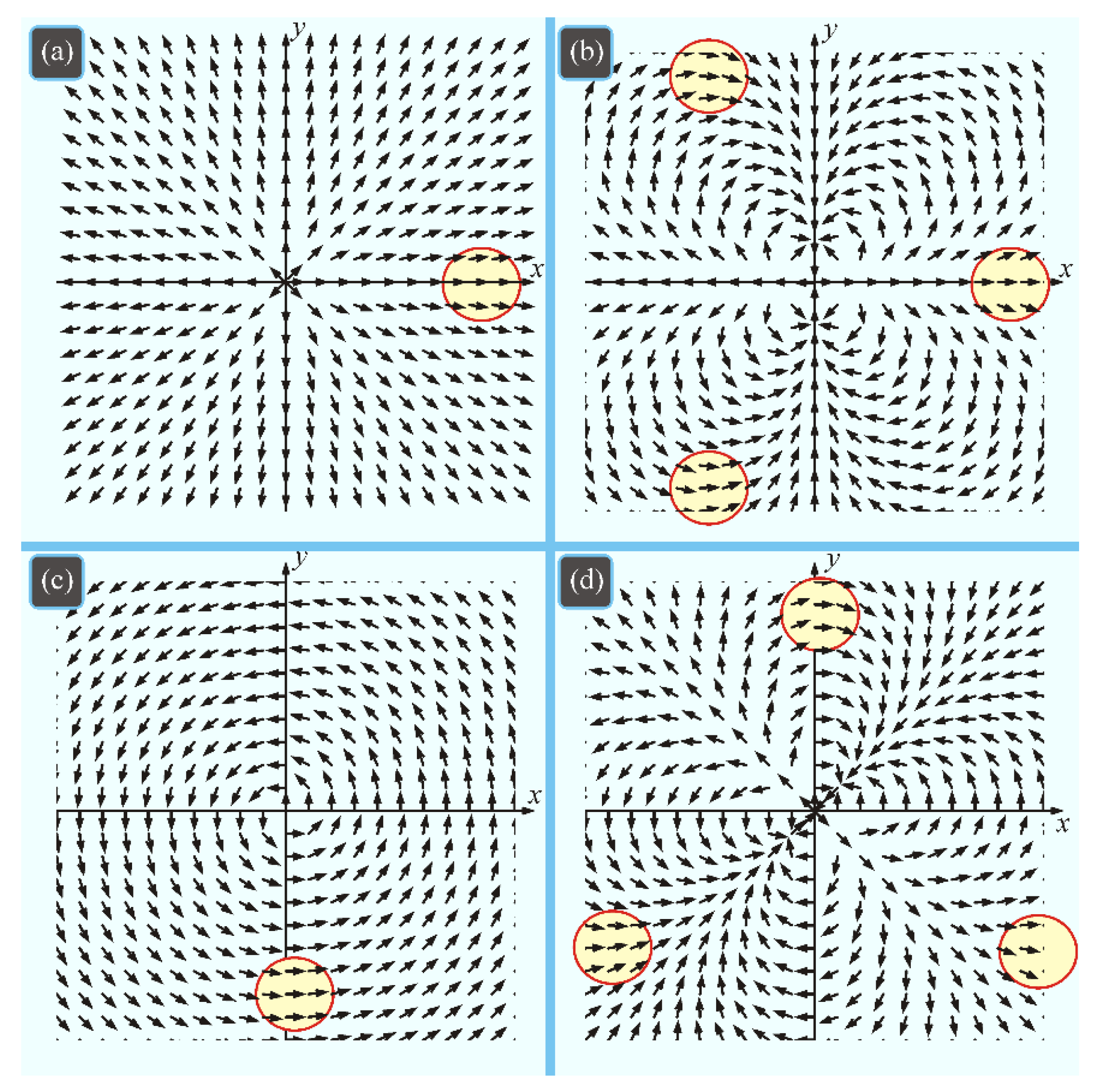
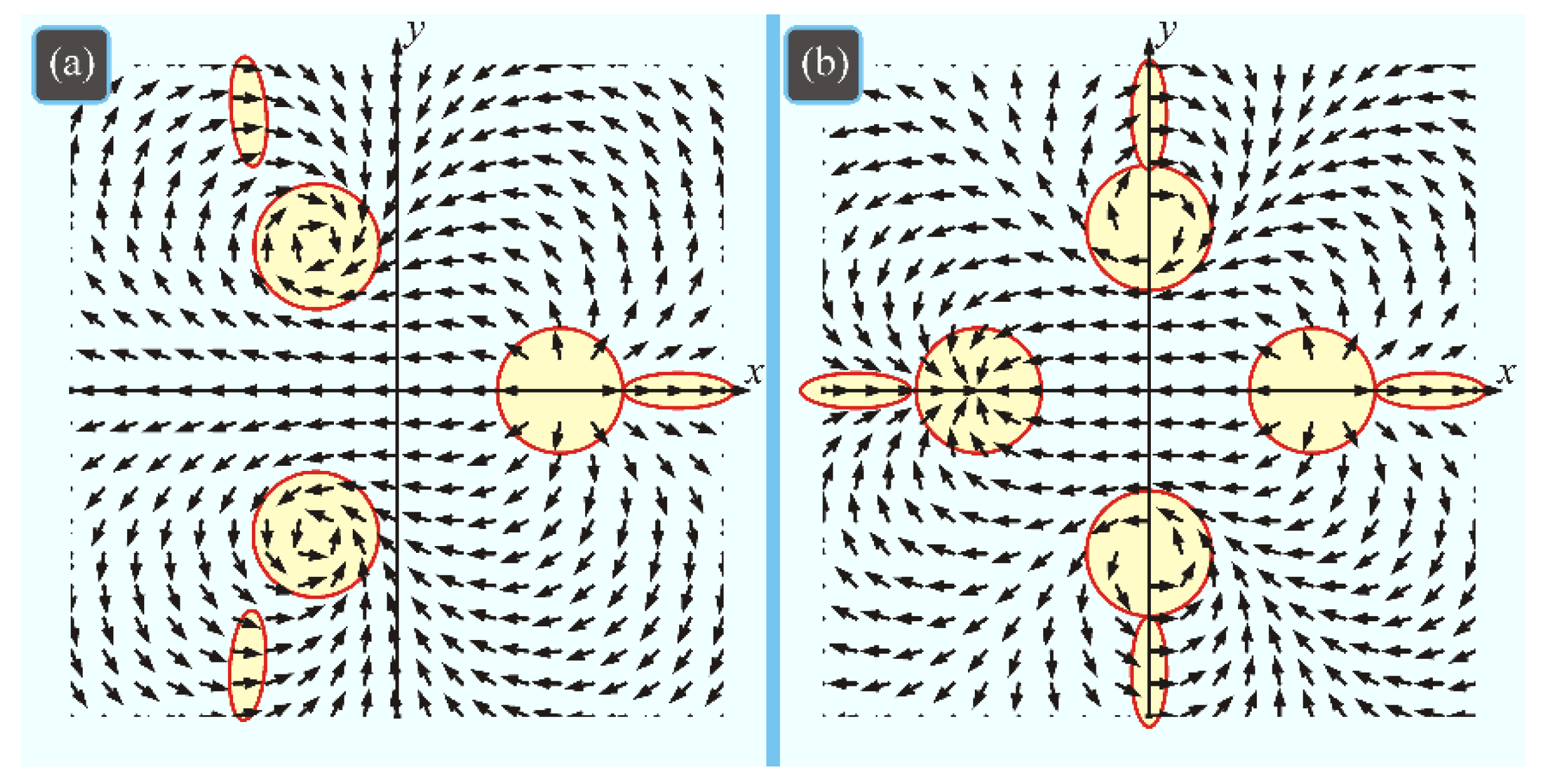
Figure 1 depicts patterns of linear polarization vectors for field (2) with (a) first- and (b) third-order radial polarization, and (c) first- and (d) third-order azimuthal polarization.
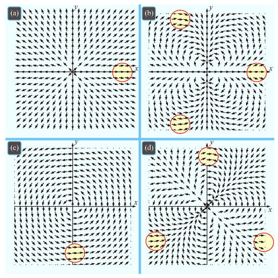
Figure 1.
Jones vectors for fields with (a) first- and (b) third-order radial polarization (n = 1, 3), and (c) first- and (d) third-order azimuthal polarization (n = 1, 3). Encircled regions highlight the polarization vectors directed to the right.
Counting the number of regions in Figure 1 where polarization vectors are directed in a definite manner (e. g. to the right) proves that the Poincare–Hopf index η of field (2) equals n.
4. PSI of a Generalized Varied-Order Vector Field
4.1. Calculation of the PSI for Generalized Vector Fields
A generalized varied-order cylindrical vector field was discussed in [12], with the corresponding Jones vector defined as follows:
In the case of the real-valued projections of the vector field onto the Cartesian axes, the PSI is easier to derive by directly constructing a scalar complex field in the following form:
In view of Equation (1), the Poincare–Hopf index for vector field (8) is given by the following equation:
A number of relationships have been shown [12] to hold for the PSI of Equation (10), as follows:
It has also been shown [12] that if n + m is odd, the PSI equals zero, if one of the orders is a unit, the PSI is also a unit in the absolute value (i.e., ηn1 = 1, η1m = (−1)(m−1)/2).
4.2. Numerical Simulation of Generalized Vector Fields
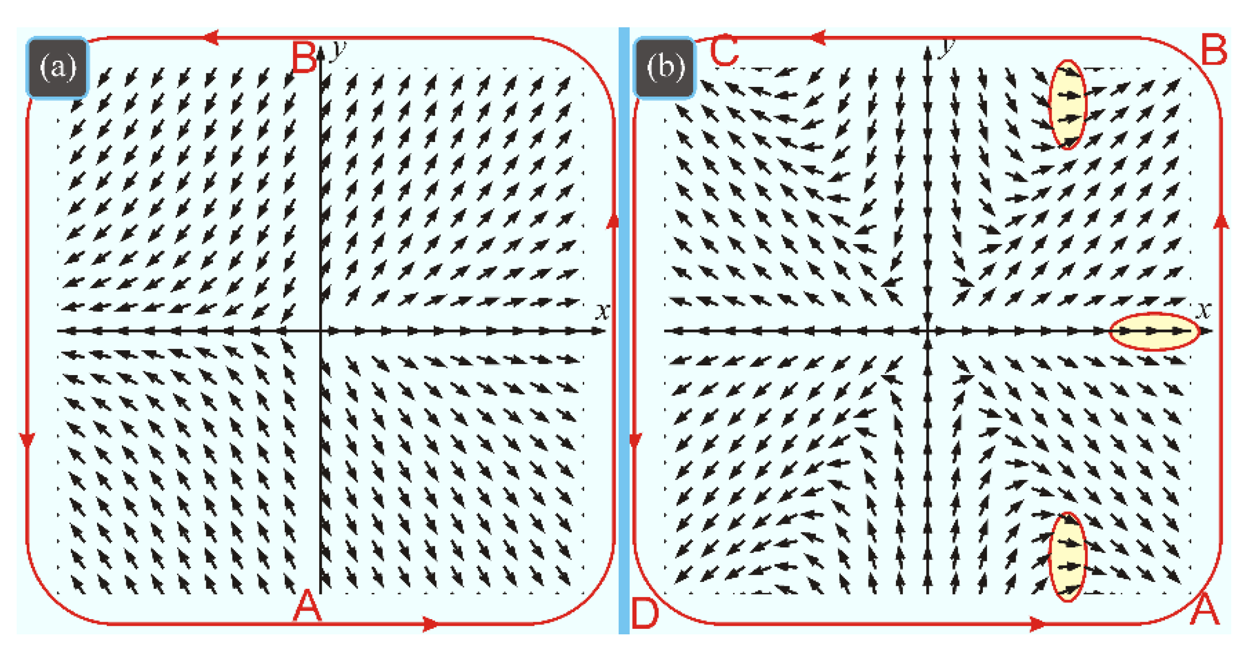
Figure 2 depicts the patterns of linear polarization vectors at the cross-section of beam (8) for the same- and different-parity orders.
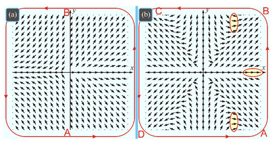
Figure 2.
Jones vectors for generalized field of orders (a) (n, m) = (1, 2) and (b) (n, m) = (1, 3). Letters A, B, C, and D mark segment boundaries for a contour along which the field vector tilt to the x-axis increases or decreases. The ellipses show the areas with the horizontal polarization (rightwards).
The anticlockwise execution of the field contour in Figure 2a shows that the angle of the polarization vector tilt to the x-axis at first increases by π (section AB) and then decreases by π (section BA). This serves to prove that the Poincare–Hopf index of the field in Figure 2a equals zero. In Figure 2b, there are three peripheral regions in which the polarization vector is directed to the right. However, unlike Figure 1b,d, the Poincare–Hopf index does not equal three, since upon the anticlockwise execution of the contour the polarization vector tilt to the x-axis increases by π/2 in sections AB and CD and decreases by 3π/2 in the sections BC and DA. Hence, the Poincare–Hopf index in Figure 2b equals −1 ((π/2 − 3π/2 + π/2 − 3π/2)/(2π) = −1), which is in agreement with Equation (11).
5. PSI of Higher-Order Fields with Hybrid Radial-Circular and Azimuthal-Circular Polarization
5.1. Calculation of the PSI for Linearly-Circular Hybrid Field
Hybrid light fields with radial-circular and azimuthal-circular polarization were first introduced in [13] and, respectively, described by Jones vectors in the following form:
The Stokes vector for the right field in Equation (12) takes the following form:
Field (12) is polarized circularly at angles and polarized linearly at angles . Stokes parameters (13) do not allow the PSI of field (12) to be determined. Hence, we conclude that field (12) has no singularity points.
The fields ERC and EAC in Equation (12) are elliptically polarized at each point, with the axes of polarization ellipses being directed along the Cartesian x- and y-axes [14,15].
5.2. Numerical Simulation for the Field with Hybrid Polarization
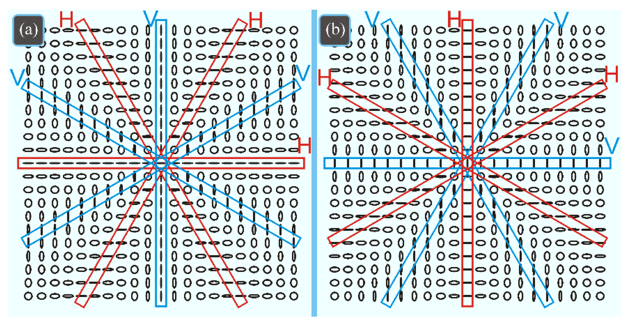
Thus, we conclude that at angles φ = πm/n (m is an arbitrary number) the field vector for ERC is directed horizontally, being directed vertically for EAC. This conclusion is confirmed by Figure 3, which depicts the Jones vectors for third-order hybrid radially-circular (a) and azimuthally-circular (b) polarized fields.
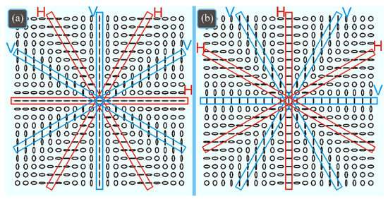
Figure 3.
Jones vectors for fields with third-order hybrid (a) radial-circular and (b) azimuthal-circular polarization (n = 3). Regions with linear polarization are marked with oblong rectangles. Letters H and V, respectively, mark regions of horizontal and vertical linear polarization.
6. PSI for a Hybrid Vector Field with Parameter
6.1. Calculation of the PSI for a Parametric Hybrid-Polarization Vector Field
A high-order hybrid vector field with parameter a was first introduced in [16] and described by a Jones vector given by the following:
At the origin, field (14) has a single singularity point (different from V- and C-points). The Stokes parameters for this field are as follows:
At definite angles, when cos(nφ) = ±1 and a = 1, the C-lines of circular polarization are found in field (14). A complex Stokes field for vector (15) takes the following form:
Substituting (16) into (6) yields the Stokes index for the hybrid field in Equation (14) as follows:
From (17), we find the following:
Equation (18) suggests that at a = 1 the vector field may have a half-integer PSI.
6.2. Numerical Simulation the Parametric Hybrid-Polarization Vector Field
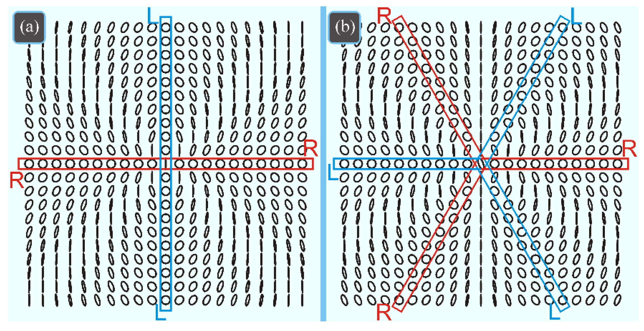
Figure 4 depicts the patterns of polarization vectors for the hybrid vector field in Equation (14) at a = 1 for even (n = 2) and odd (n = 3) orders.
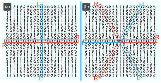
Figure 4.
Jones vectors for hybrid vector field with parameter a = 1 at (a) n = 2 and (b) n = 3. Regions of circular polarization (C-lines) are marked with rectangles. Letters R and L denote regions with right- and left-hand circular polarization.
From Figure 4a it can be seen that when making a full circle around the center, the major axis of the right-hand polarization axis rotates by 2π, i.e., η = 2π/(2π) = 1. Whereas from Figure 4b, the major axis of the right-hand polarization axis is seen to rotate thrice when making a full circle of 2π around the center. Hence, η = 3π/(2π) = 3/2, which is in agreement with Equation (18).
7. Fields with Multiple Singularity Points
7.1. Calculation of the PSI for the Field with Multiple Singularities
In [5], we proposed a vector field containing n singularity points arranged on a circle of radius a and described by the Jones vectors given by the following equation:
The vector field with several singularities cannot depend only on the polar angle φ, but should also depend on the radial variable r in Equation (19).
With the projections of the field in Equation (19) being real, the corresponding PSI can be derived by using a relationship for a scalar complex field, as follows:
The topological charge of the scalar field in (20) is derived by using the Berry Formula (1), taking the following form:
For comparison, let us find the PSI of field (19) using Stokes parameters defined as follows:
From (22), and because S3 = 0, field (19) is seen to be locally linear polarized. A complex Stokes field takes the following form:
Using Equations (23) and (6), the Stokes index for field (19) is expressed as follows:
Equations (21) and (24) lead to the same result of η = n.
7.2. Numerical Simulation for the Field with Multiple Singularities
Figure 5 depicts patterns of the linear polarization vectors in the cross-section of beam (19) with (a) three (n = 3) and (b) four (n = 4) polarization singularity points at a = R/2 (R is half-size of the computational domain). It also can be seen that, in the case of four singularities, there are two points with radial polarization and two points with azimuthal polarization [5].
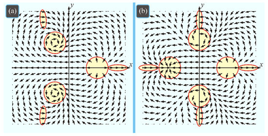
Figure 5.
Jones vectors for field (19) with (a) three (n = 3) and (b) four (n = 4) polarization singularity points found at a distance of a = R/2 (R is half-size of the computational domain) from the optical axis. Polarization singularity points are marked with circles, while ellipses highlight field regions where the polarizations vectors are directed to the right.
From Figure 5a,b, the number of peripheral regions with a particular polarization vector direction (e.g., right) is seen to equal that of the polarization singularities. We also observe that, when passing from one such a region to the other, the tilt of the field vector to the x-axis increases. Thus, Figure 5 corroborates that η = n.
8. A Vector Light Field with Several Singularity Lines
8.1. Calculation of the PSI for a Field with Several Singularity Lines
If the radial variable r is taken out from Equation (19), instead of n polarization singularity points there are n singularity lines (V-lines, also referred to as L-lines), with the entire field remaining linearly polarized at each point. The Jones vector can be given as follows:
We can derive the PSI of field (25) in an easy way, through the use of a scalar complex field, as follows:
Applying (1) to field (26) yields the following:
Equation (27) suggests that, unlike field (24), the PSI of field (25) can be both integer and half-integer, as is the case with field (19). This is because at a = 1, field (25) has n V-lines outgoing from the center at angles . Thanks to the presence of V-lines in field (25), the initial plane is broken down into n sectors, with the linear polarization vector direction jumping by π when crossing a V-line. Hence, the number of V-lines determines the number of times that the polarization vector jumps by π when making a full circle around the origin. So, we conclude that η = nπ/(2π) = n/2. At a = −1, the V-lines of field (25) outgo from the center at angles . At a = 0, field (25) becomes a conventional radially polarized high-order field of Equation (2), with a single V-point at the center.
8.2. Numerical Simulation of a Field with Several Singularity Lines
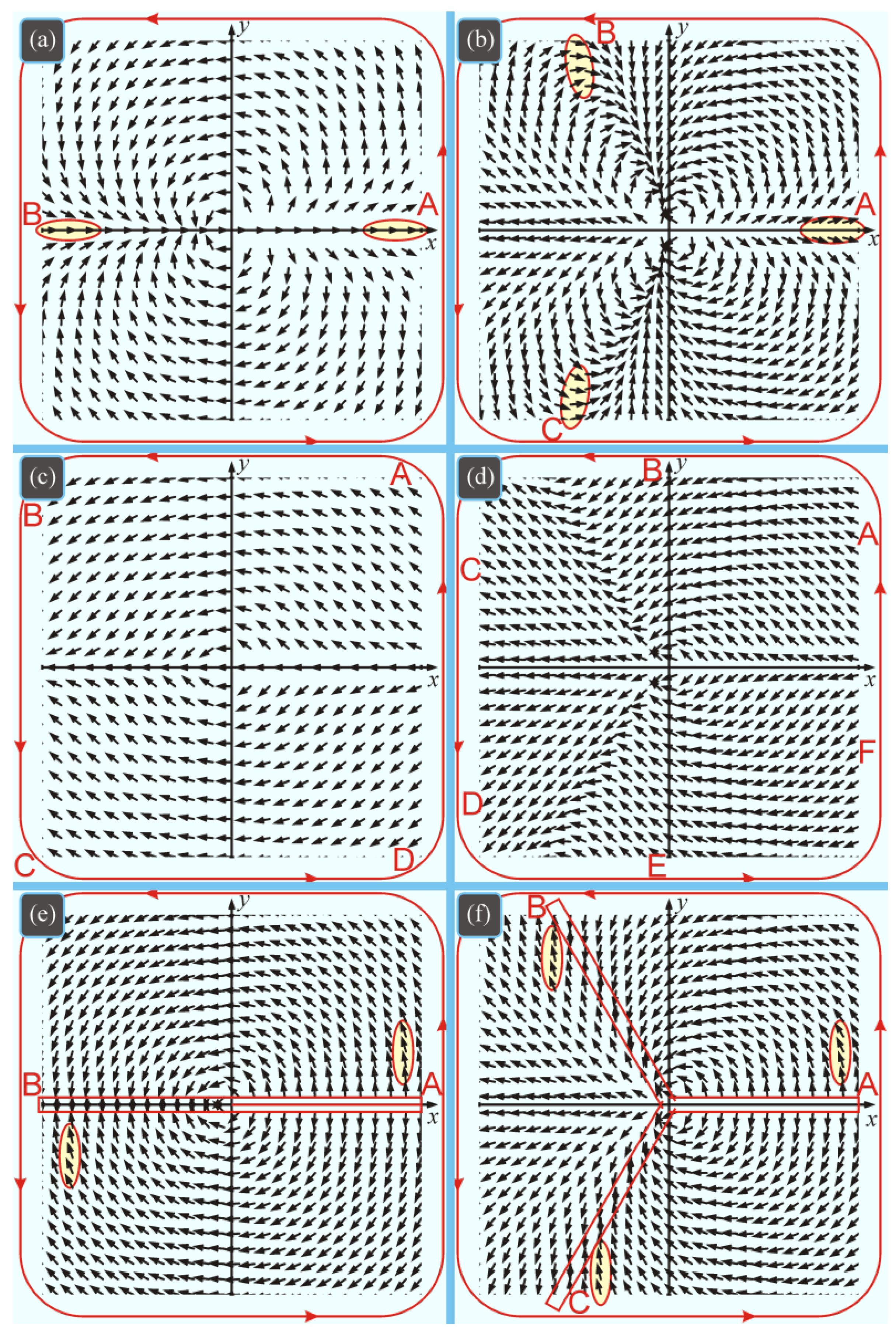
Figure 6 shows the patterns of linear polarization vectors at the cross-section of beam (25) of the second (n = 2) and third (n = 3) order at a = 1/2, a = 3/2, and a = 1.
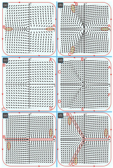
Figure 6.
Jones vectors of field (25) of orders (a,c,e) (n = 2) and (b,d,f) (n = 3) at a = 1/2 (a,b), a = 3/2 (c,d), and a = 1 (e,f). Ellipses mark regions where the polarization vector is directed (a,b) to the right or (e,f) upwards. Letters A, B, C, D, E, and F mark segment boundaries for a contour along which the field vector tilt to the x-axis increases or decreases. Rectangles mark V-lines (e,f).
From Figure 6a,b, the number of peripheral regions with a particular polarization vector direction (e.g., right) equals the order n. Besides, when passing from one such region to the other, the tilt of the field vector to the x-axis increases by 2π (from A to B and from B to A in Figure 6a, from A to B, from B to C, and from C to A in Figure 6b). Hence, Figure 6a,b confirms that η = n at |a| < 1.
From Figure 6c,d it can be seen that, unlike Figure 6a,b, when executing the contour over the field, the angle of the field vector tilt to the x-axis alternately increases and decreases. For instance, in Figure 6c the angle at first increases by about π/2 at sections AB and CD before decreasing by the same value at sections BC and DA. In a similar way, in Figure 6d the vector tilt angle increases at sections AB, CD, and EF, before decreasing at BC, DE, and FA. Thus, the patterns in Figure 6c,d confirm that η = 0 at |a| > 1.
Figure 6e,f shows that when making a full circle around the field, the field vector tilt to the x-axis is seen first to increase but then to start jumping by π each time it crosses one of n V-lines. Therefore, the tilt angle increases by π at sections AB and BA in Figure 6e, and at sections AB, BC, and CA in Figure 6f. Thus, the patterns in Figure 6e,f confirm that η = n/2 at |a| = 1.
9. An Optical Vortex with Polarization Singularity
9.1. Calculation of the PSI for a Vortex with Polarization Singularity
Below, we analyze a vortex light field with topological charge m and nth-order cylindrical polarization. In this case, the Jones vector is given as follows:
where δ is constant. Two projections of field (28) that form a scalar complex field, as follows:
have a topological charge TC = m + n. In Equation (29), both the phase and the polarization singularities equally contribute to the net TC of the complex field. However, using the Stokes parameters for field (28) as follows:
and complex field (29) as follows:
we find that the PSI is σ = 2η = 2n, being independent of m. Thus, the polarization singularities can be looked into in a dual way. The use of the Stokes parameters gives the PSI equal to n, whereas the relationship for the complex field in Equation (29) suggests that TC of such a field equals m + n.
9.2. Numerical Simulation for a Vortex with Polarization Singularity
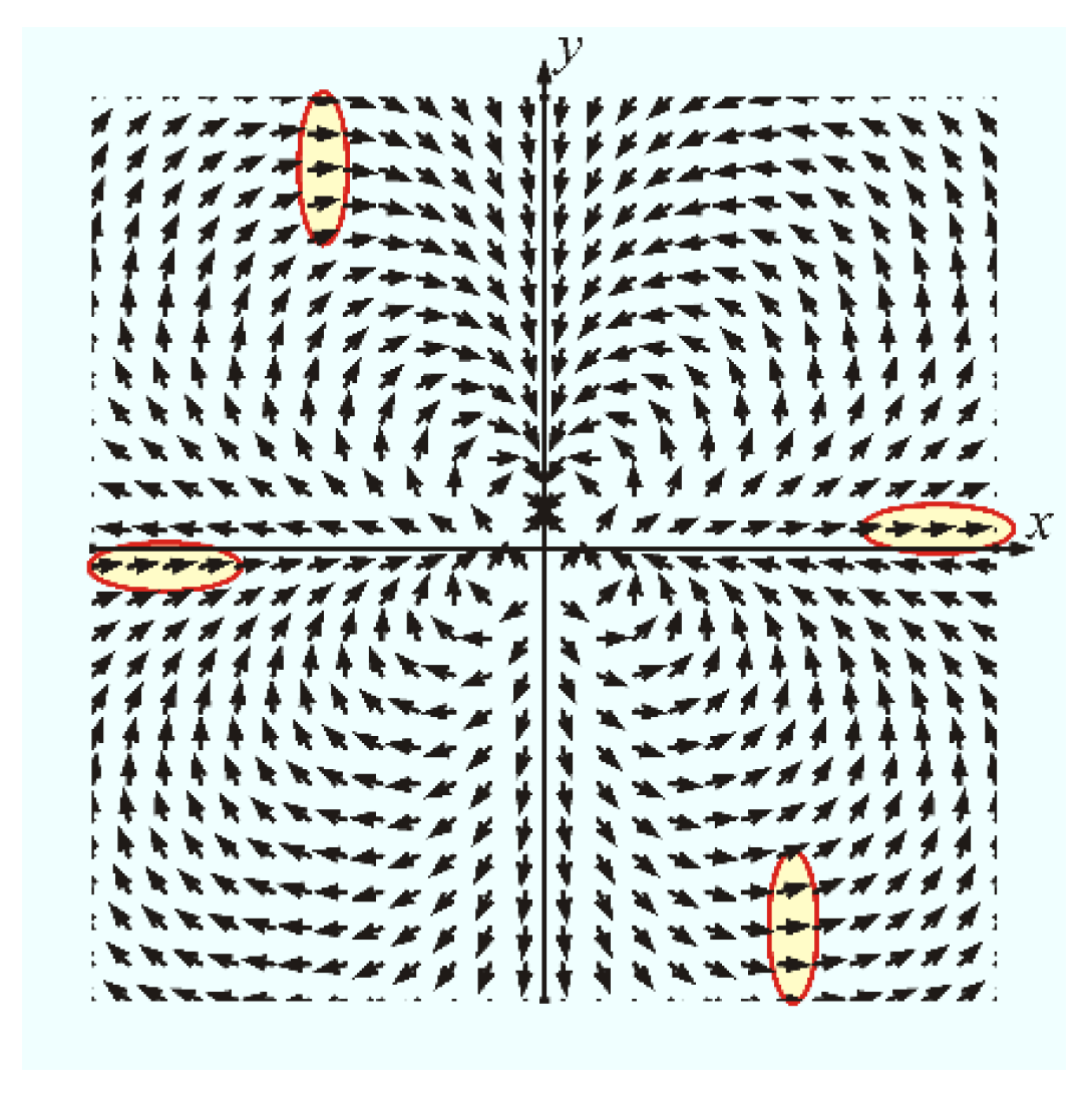
Figure 7 shows a pattern of Jones vectors for vortex field (28) with first-order phase singularity (m = 1) and the third-order polarization singularity (n = 3) at δ = 0. We note that field (28) is not able to depict at any value of φ, since the Jones vector in (28) contains a phase term. Therefore, at m = 1, field (28) is depicted on the assumption of (i) exp(iφ) = 1 at the upper semi-plane (y > 0) and (ii) exp(iφ) = −1 at the lower semi-plane (y < 0).
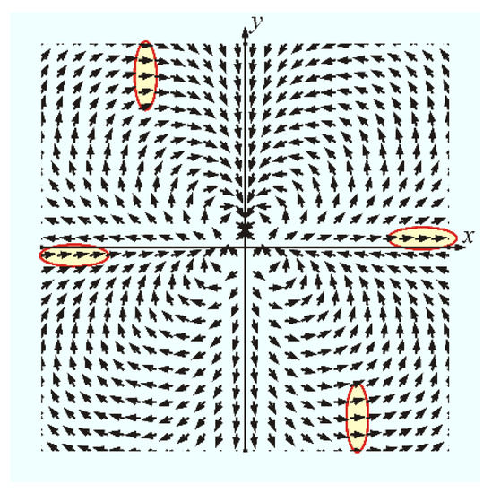
Figure 7.
Jones vectors of a first-order optical vortex (m = 1) with a third-order polarization singularity (n = 3).
Four peripheral regions with a particular (e.g., right) polarization direction are seen to be present in Figure 7, therefore the PSI is equal to m + n.
10. Calculation of the PSI for the Poincare Beams
For light beams whose polarization state is described by unit vectors on a Poincare sphere, the Jones vector is given by [17,18] as follows:
where , and θ and are the polar and azimuthal angles on the sphere. The Stokes vector has the following coordinates:
From (33), a Poincare beam is seen to be circularly polarized if the following applies:
In view of Equation (33), a complex Stokes field takes the following form:
From (35), it follows that the PSI of field (32) equals the following:
From Equation (36), the PSI of the field is seen to be equal to n, with the field having inhomogeneous linear polarization if both a and b are non-zero. The field is circularly polarized and has no singularity (η = 0) if either a or b is equal to zero.
11. Calculation of the PSI for a Vector Field in a Uniaxial Crystal
The propagation of optical vortices in uniaxial crystals was reported in [19]. The Jones vector of light fields in a uniaxial crystal is given by the following equation:
where γ is the phase shift between ordinary and extraordinary rays in a paraxial case and φ is the polar angle at the beam cross-section. The Stokes parameters are given by the following equation:
In view of Equation (38), a complex Stokes field takes the following form:
From (39), the PSI of field (37) is seen to be given by the following equation:
Interestingly, if the phase shift is γ = π, then η = 0, which means that the light field in the uniaxial crystal is a circularly polarized optical vortex with TC = 2. If γ = 0, a nonvortical circularly polarized optical beam propagates in the crystal.
12. A Light Field with Radially Varied Inhomogeneous Polarization
12.1. Calculation of the PSI for Beams with Radially Varied Polarization
In the previous sections, we discussed the light fields whose polarization state varied only with the polar (azimuthal) angle φ (except for field (19)). Below, we discuss a light field that was introduced in [20] with its polarization state varying only with the radius. The Jones vector of such a field is given by the following equation:
where R is a scale factor. The Stokes vector components for field (41) are given by the following equation:
From (42), field (41) is seen to have the right-handed circular polarization along radii that satisfy the condition of , with the left-handed circular polarization found on the radii and linear polarization on the radii . For field (41), and any other similar field with a pure radial-variable-dependent polarization state, when making a full circle of an arbitrary radius around the beam center, neither the direction of the linear polarization vectors nor the direction of the major semi-axis of the elliptic polarization vectors change. Thus, we conclude that fields with radial-variable-dependent polarization have no singularity points with their PSI being zero.
12.2. Numerical Simulation for Beams with Radially Varied Polarization
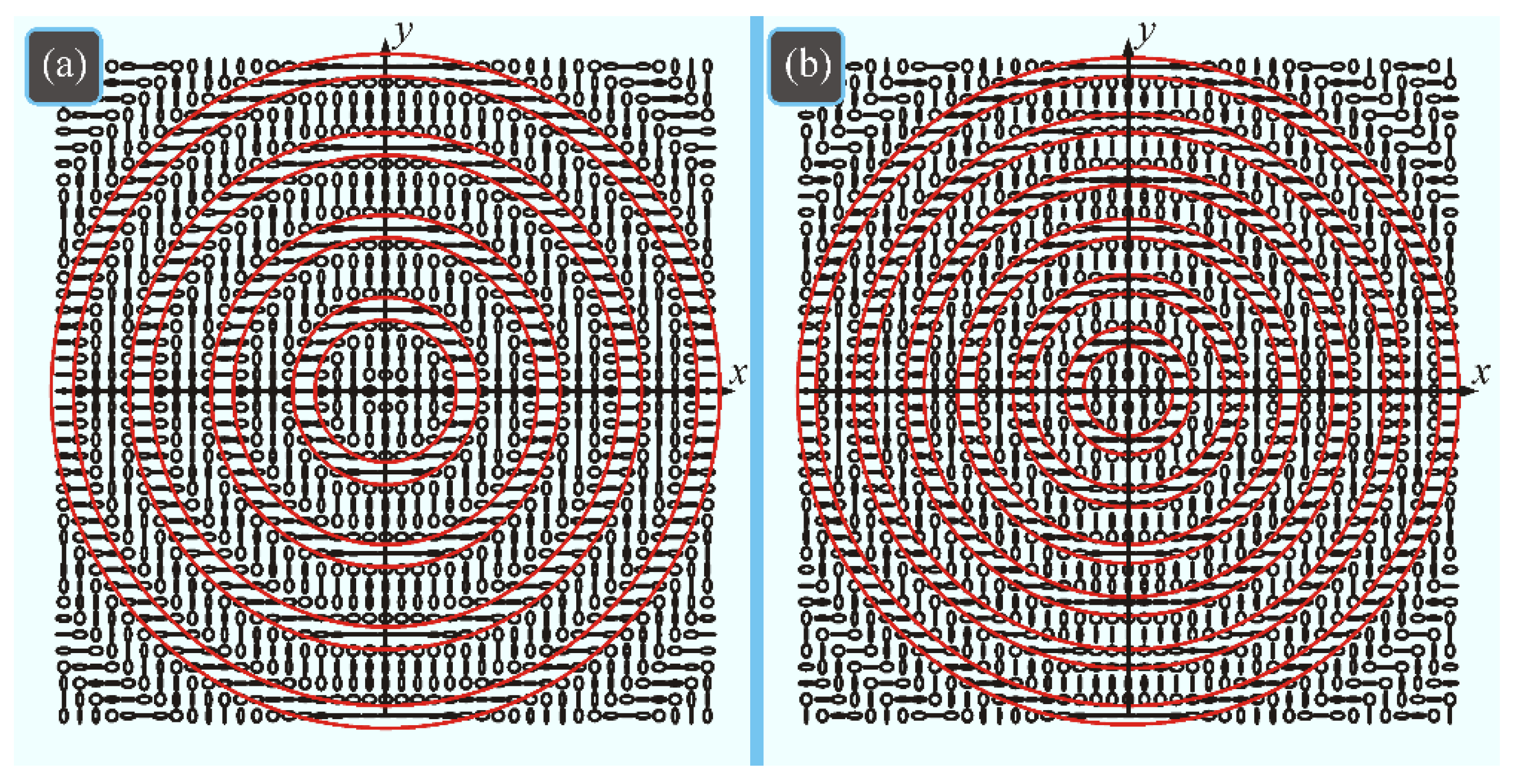
Figure 8 depicts the patterns of linear (lines) and circular polarization states at the cross-section of beam (41) for n = 2 (a) and n = 3 (b).
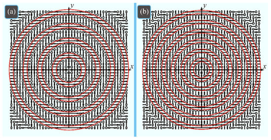
Figure 8.
Jones vectors for field (41) with radially varied inhomogeneous polarization at (a) n = 2 and (b) n = 3. Regions with horizontal linear polarization are within circles.
Figure 8 shows that, within a circle of radius r ≤ R, at the cross-section of field (41) there are 4n annular regions of radius r = mR/(4n) with linear polarization (in particular, depicted in Figure 8 are rings of radii r = mR/(2n)) with horizontal linear polarization), with circularly polarized regions found in between (C-lines and C-rings).
13. Discussion of the Results
In this section, the PSI derived for different types of fields are summarized and compared in Table 1.

Table 1.
Comparison of high-order vector fields and their PSI.
Table 1 suggests that, for the hybrid fields ERC, EH, and EP, the third Stokes vector component can be non-zero at some values of the polar angle φ and parameters a and b. Meanwhile, the PSI η can take arbitrary values as follows: zero (ERC), half-integer (EH), or integer (EP). For the pure vectorial light fields ER, EnS, and EnV, the third Stokes vector component equals zero (S3 = 0), whereas the PSI can be integer (ER, EnS), half-integer, and zero (EnV). It is worth noting that the third component of the non-normalized Stokes vector S3 (3) is coincident with the longitudinal projection of the spin angular moment Sz, as follows:
Out of all of the types of fields in Table 1, the only field that depends on both of the polar coordinates is the vector field EnS, which has n polarization singularity points uniformly arranged on a certain circumference. For the rest of the fields, the polarization singularity point of integer or half-integer order is found on the optical axis at the origin of the coordinates. The only field that is devoid of polarization singularities is the field ERC.
14. Conclusions
In summary, we have proposed a new vector light field EnV with inhomogeneous linear polarization and high order n that depends on a real parameter. A comparative analysis of the proposed field with familiar vector and hybrid light fields that have polarization singularity points has been conducted. For all of the light fields considered, PSIs have been determined. It has been shown that, in the new vector field, the V-point of polarization singularity is on the optical axis, whereas the PSI can be integer (equal to the order n), half-integer (n/2), and zero. Having analyzed seven different vector and hybrid fields, including those with multiple polarization singularity points, we have found the PSI using the familiar Berry formula, which is ordinarily utilized for determining the topological charge of scalar vortex light fields. For fields whose polarization state at the cross-section depends only on the distance to the beam center, it has been shown that the PSI equals zero.
Author Contributions
Conceptualization, V.V.K.; methodology, A.A.K.; formal analysis, V.V.K.; software, A.A.K. and V.D.Z.; writing—original draft preparation, A.A.K.; writing—review and editing, V.V.K. All authors have read and agreed to the published version of the manuscript.
Funding
This research was partly funded by the RUSSIAN SCIENCE FOUNDATION under grant # 22-22-00265 (theory) and the RF MINISTRY OF SCIENCE AND HIGHER EDUCATION under the state project of the FSRC “Crystallography and Photonics” RAS (numerical modeling).
Institutional Review Board Statement
Not applicable.
Informed Consent Statement
Not applicable.
Data Availability Statement
Not applicable.
Conflicts of Interest
The authors declare no conflict of interest.
References
- Freund, I. Poincaré vortices. Opt. Lett. 2001, 26, 1996–1998. [Google Scholar] [CrossRef] [PubMed]
- Freund, I. Polarization singularity indices in Gaussian laser beams. Opt. Commun. 2002, 201, 251–270. [Google Scholar] [CrossRef]
- Freund, I.; Mokhun, A.I.; Soskin, M.S.; Angelsky, O.V.; Mokhun, I.I. Stokes singularity relations. Opt. Lett. 2002, 27, 545–547. [Google Scholar] [CrossRef] [PubMed]
- Vyas, S.; Kozawa, Y.; Sato, S. Polarization singularities in superposition of vector beams. Opt. Express 2013, 21, 8972–8986. [Google Scholar] [CrossRef] [PubMed]
- Kovalev, A.A.; Kotlyar, V.V. Fresnel and Fraunhofer diffraction of a Gaussian beam with several polarization singularities. Computer Optics 2018, 42, 179–189. [Google Scholar] [CrossRef]
- Senthilkumaran, P.; Pal, S.K. Phase singularities to polarization singularirities. Int. J. Opt. 2020, 2020, 2812803. [Google Scholar]
- Komal, B.; Deepa, S.; Kumar, S.; Senthilkumaran, P. Polarization singularity index determination by using a titled lens. Appl. Opt. 2021, 60, 3266–3271. [Google Scholar] [CrossRef]
- Berry, M.V. Optical vortices evolving from helicoidal integer and fractional phase steps. J. Opt. A Pure Appl. Opt. 2004, 6, 259–268. [Google Scholar] [CrossRef]
- Zhan, Q. Cylindrical vector beams: From mathematical concepts to applications. Adv. Opt. Photon. 2009, 1, 1–57. [Google Scholar] [CrossRef]
- Kolyar, V.V.; Stafeev, S.S.; Kovalev, A.A. Sharp focusing of a light field with polarization and phase singularities of an arbitrary order. Computer optics 2019, 43, 337–346. [Google Scholar] [CrossRef]
- Born, M.; Wolf, E. Principles of Optics; “Nauka” Publisher: Moscow, Russia, 1973; 720p. [Google Scholar]
- Kotlyar, V.V.; Kovalev, A.A.; Stafeev, S.S.; Nalimov, A.G.; Rasouli, S. Tightly focusing vector beams containing V-point polarization singularities. Opt. Las. Tech. 2022, 145, 107479. [Google Scholar] [CrossRef]
- Kotlyar, V.V.; Stafeev, S.S.; Kozlova, E.S.; Nalimov, A.G. Spin-Orbital Conversion of a Strongly Focused Light Wave with High-Order Cylindrical–Circular Polarization. Sensors 2021, 21, 6424. [Google Scholar] [CrossRef] [PubMed]
- Dennis, M.R. Polarization singularities in paraxial vector fields: Morphology and statistics. Opt. Commun. 2002, 213, 201–221. [Google Scholar] [CrossRef] [Green Version]
- Berry, M.V. Index formulae for singular lines of polarization. J. Opt. A Pure Appl. Opt. 2004, 6, 675–678. [Google Scholar] [CrossRef]
- Kotlyar, V.V.; Stafeev, S.S.; Nalimov, A.G. Sharp focusing of a hybrid vector beam with a polarization singularity. Photonics 2021, 8, 227. [Google Scholar] [CrossRef]
- Beckley, A.M.; Brown, T.G.; Alonso, M.A. Full Poincaré beams. Opt. Express 2010, 18, 10777–10785. [Google Scholar] [CrossRef]
- Chen, S.; Zhou, X.; Liu, Y.; Ling, X.; Luo, H.; Wen, S. Generation of arbitrary cylindrical vector beams on the higher order Poincaré sphere. Opt. Lett. 2014, 39, 5274–5276. [Google Scholar] [CrossRef] [Green Version]
- Volyar, A.V.; Fadeeva, T.A. Generation of singular beams in uniaxial crystals. Optics and Spectroscopy 2003, 94, 235–244. [Google Scholar] [CrossRef]
- Li, T.; Cao, B.; Zhang, X.; Ma, X.; Huang, K.; Lu, X. Polarization transitions in the focus of radial-variant vector circular Airy beams. J. Opt. Soc. Am. A 2019, 36, 526–532. [Google Scholar] [CrossRef]
- Rashid, M.; Marago, O.M.; Jones, P.H. Focusing of high order cylindrical vector beams. J. Opt. A Pure Appl. Opt. 2009, 11, 065204. [Google Scholar] [CrossRef]
- Kotlyar, V.V.; Stafeev, S.S.; Kovalev, A.A. Reverse and toroidal flux of light fields with both phase and polarization higher-order singularities in the sharp focus area. Opt. Express 2019, 27, 16689–16702. [Google Scholar] [CrossRef] [PubMed]
Publisher’s Note: MDPI stays neutral with regard to jurisdictional claims in published maps and institutional affiliations. |
© 2022 by the authors. Licensee MDPI, Basel, Switzerland. This article is an open access article distributed under the terms and conditions of the Creative Commons Attribution (CC BY) license (https://creativecommons.org/licenses/by/4.0/).

