Communication

Mode Coupling and Steady-State Distribution in Multimode Step-Index Organic Glass-Clad PMMA Fibers

1
Faculty of Science, University of Kragujevac, R. Domanovića 12, 34000 Kragujevac, Serbia
2
Department of Mechanical Engineering, City University of Hong Kong, 83 Tat Chee Avenue, Hong Kong, China
3
Laboratory of Neurodegenerative Disease, School of Biomedical Sciences, LKS Faculty of Medicine, The University of Hong Kong, Hong Kong, China
4
Center for Cognition and Neuroergonomics, State Key Laboratory of Cognitive Neuroscience and Learning, Beijing Normal University, Zhuhai 519087, China
*
Author to whom correspondence should be addressed.
Photonics 2022, 9(5), 297; https://doi.org/10.3390/photonics9050297
Submission received: 24 March 2022 / Revised: 25 April 2022 / Accepted: 26 April 2022 / Published: 27 April 2022
(This article belongs to the Special Issue Application of Multimode Optical Fibers)

Abstract

:
Mode coupling and power diffusion in multimode step-index (SI) organic glass-clad (OGC) PMMA fiber is examined in this study using the power flow equation (PFE). Using our previously proposed approach we determine the coupling coefficient D for this fiber. When compared to standard multimode SI PMMA fibers, the multimode SI OGC PMMA fiber has similar mode coupling strength. As a result, the fiber length required to achieve the steady-state distribution (SSD) in SI OGC PMMA fibers is similar to that required in standard SI PMMA fibers. We have confirmed that optical fibers with a plastic core show more intense mode coupling than those with a glass core, regardless of the cladding material. These findings could be valuable in communication and sensory systems that use multimode SI OGC PMMA fiber. In this work, we have demonstrated a successful employment of our previously proposed method for determination of the coupling coefficient D in multimode SI OGC PMMA fiber. This method has already been successfully employed in the previous research of mode coupling in multimode SI glass optical fibers, SI PMMA fibers and SI plastic-clad silica optical fibers.

1. Introduction

Glass optical fibers are suitable for long-haul communication systems with advantages such as low attenuation and large bandwidth [1,2]. With the demand of emerging services such as visible light communication, indoor network and intelligent home systems, the demand has shifted from long-haul communication systems to short-range ones. Indeed, PMMA fibers are perfect candidates for short range communication systems [3,4]. For light amplification and lasing, glass-clad PMMA fibers with a large core are commonly utilized [5]. Large core optical fibers, in general, ease the tolerances necessary for system interconnections, which is important for home networks [6].
A light pulse propagating consists of large number of energy packets that are distributed over modes, which are guided along the fiber. A perfect (ideal) multimode optical fiber can transmit its guided modes without energy conversion to the other guided modes or continuous (radiation) spectrum. However, a real optical fiber does not trap light perfectly, and energy is either slowly dissipated through coupling to the continuous spectrum, which radiates the energy into the cladding or couples to the remaining guided modes. Therefore, mode coupling in an optical fiber is generated by fiber imperfections and inhomogeneities, which means the transfer of energy from one mode to others during propagation, and it reflects power transmission between neighboring modes. While mode coupling decreases beam quality in power transmission, it has a favorable effect on data networks by reducing modal dispersion and thereby increasing the transmission bandwidth [7]. It is also interesting to note that due to mode coupling, principal optical characteristics (e.g., attenuation, bandwidth) of an optical fiber cannot be accurately defined until the full mode equilibrium, i.e., steady-state conditions are not yet completely achieved. Thus it is of great importance to determine the fiber length at which an SSD is established. At this length the relative energy packet population in each guided mode no longer changes with fiber length.
For light launched centrally along the multimode optical fiber axis (θ0 = 0), a disk radiation-pattern is formed at the output fiber end. In case where the width of the launch distribution is narrower than an SSD (Figure 1a), this disk broadens with the fiber length as more of the higher-order modes become excited by the coupling. In cases where the width of the launch distribution is wider than SSD (Figure 1b), this disk narrows with fiber length due to power transfer from higher to lower order modes. Since the modal dynamics during the light transmission along an optical fiber is strongly influenced by mode coupling, it is of interest to predict the width of the output angular power distribution at the end of the fiber. While mode coupling can degrade the beam quality, it reduces the broadening of transmitted signal pulses and improves fiber bandwidth.
It is worth noting that there are many different methods for the mechanical and structural characterization of various optical materials, such as PMMA [8], silica [2] and composite materials [9,10], which are used in fiber optics and optical engineering. On the other hand, until recently, commercial simulation software packages for the investigation of transmission characteristics of optical fibers, were either designed specifically for single mode optical fibers or they modeled individually guided modes in a few-mode optical fibers in considerable detail. This is not adequate for multimode optical fibers with thousands, or even millions of propagation modes, strong mode coupling and high refractive index distribution variability. Therefore, an effective simulation tool for the modeling of light propagation in multimode optical fibers made of different materials is needed. Geometric optics has been used to investigate characteristics of light transmission in multimode optical fibers [11]. The output angular power distributions have been anticipated as a function of the launch conditions and fiber length using the PFE [4,12]. In the PFE, one needed to know the coupling coefficient D, which has been proved to accurately predict coupling effects in practice. The method of determining the coupling coefficient D proposed by Gambling et al. [13] required that the far-field output pattern be observed for various fiber lengths and at different launch angles. Zubia et al. [4] proposed a method in which the coupling coefficient D is obtained by observing the far field output pattern from a fixed length of fiber as the launch angle changed, and determining the intersection point between two far-field output patterns corresponding to two different launch angles. In our earlier published work, we proposed an alternative method which enables that the coupling coefficient D can be obtained from just one far-field output pattern [14]. In comparison to Gambling et al.’s method and Zubia et al.’s method of determining the coupling coefficient D, our method is the most simplest and efficient.
The coupling coefficient D in multimode SI OGC PMMA fibers is determined in this study by employing our previously proposed method [14]. To determine its mode coupling characteristics, we have to solve the PFE. This enables us to determine the length at which the SSD is established in the analyzed fiber. The SSD’s results are checked against an analytical solution. It should be mentioned that one of the main novelties in this paper is that we measure not only the strength of mode coupling, but we also obtain the far-field patterns for a centrally launched beam at different SI OGC PMMA fiber lengths.

2. Power Flow Equation

Assuming that propagating modes in a multimode optical fiber are in the form of modal continuum, as well as that coupling occurs only between adjacent modes, Gloge proposed the PFE in the form [12]:
P ( θ , z ) z = α ( θ ) P ( θ , z ) + D θ θ θ P ( θ , z ) θ
where P(θ,z) is the angular power distribution at fiber length z, θ is the propagation angle with respect to the core axis, D is the assumed constant coupling coefficient [4,12,13,14], and α(θ) is the modal attenuation. Since only relative modal power distribution is of interest, α(θ) may be removed from the Equation (1), therefore Equation (1) reduces to:
P ( θ , z ) z = D θ P ( θ , z ) θ + D 2 P ( θ , z ) θ 2
By numerically solving the PFE (2) one can obtain the output angular power distribution at an arbitrary fiber length. The steady-state solution of Equation (2) is given by:
P ( θ , z ) = J 0 2.405 θ θ c exp ( γ 0 z )
where J0 is the Bessel function of the first kind and zero order and γ 0 m 1 = 2.405 2 D / θ C 2 is the attenuation coefficient. This solution was utilized to validate our numerical results for the case where the SSD is established.

3. Method for Calculating Coupling Coefficient D

When the launch beam distribution is narrower than the SSD (Figure 1a), coupling coefficient D in multimode optical fiber is given by [14]:
D = σ z 2 2 σ z 1 2 2 ( z 2 z 1 )
where σ Z 1 2 and σ Z 2 2 are variances of the distribution P(θ,z) measured at the fiber lengths z1 > 0 and z2 > 0 (z2 > z1), respectively. When the launch beam distribution is wider than the SSD (Figure 1b), coupling coefficient D in multimode optical fiber is given by [14]:
D = σ z 1 2 σ z 2 2 2 ( z 2 z 1 )
where σ Z 1 2 and σ Z 2 2 are variances of the distribution P(θ,z) measured at the fiber lengths z1 > 0 and z2 > 0 (z2 > z1), respectively.
In this work we demonstrate that propagation properties of multimode SI OGC PMMA fibers can be successfully predicted using the coupling coefficient D, which can be determined using Equation (4) or (5).

4. Results and Discussion

In this study we use our previously proposed approach for determining the coupling coefficient D [14] for the multimode SI OGC PMMA fiber used in Dugas et al.’s experiment [15]. The optical fiber utilized by Dugas et al. [15] is Dupont’s CROFON-OE1040 (CROFON fiber). The fiber’s core was mainly made of PMMA, while its cladding is made of organic glass with fluorine. This fiber had a d = 1 mm core diameter, core refractive index n0 = 1.4877, numerical aperture NA = 0.506, and modal attenuation α(θ)≡¦Á = 396 dB/km [15]. The number of modes in this multimode SI OGC PMMA fiber, for λ = 633 nm, is: N = 2 π 2 a 2 ( NA ) 2 / λ 2 = 3.2 × 10 6 , where a is a core radius.
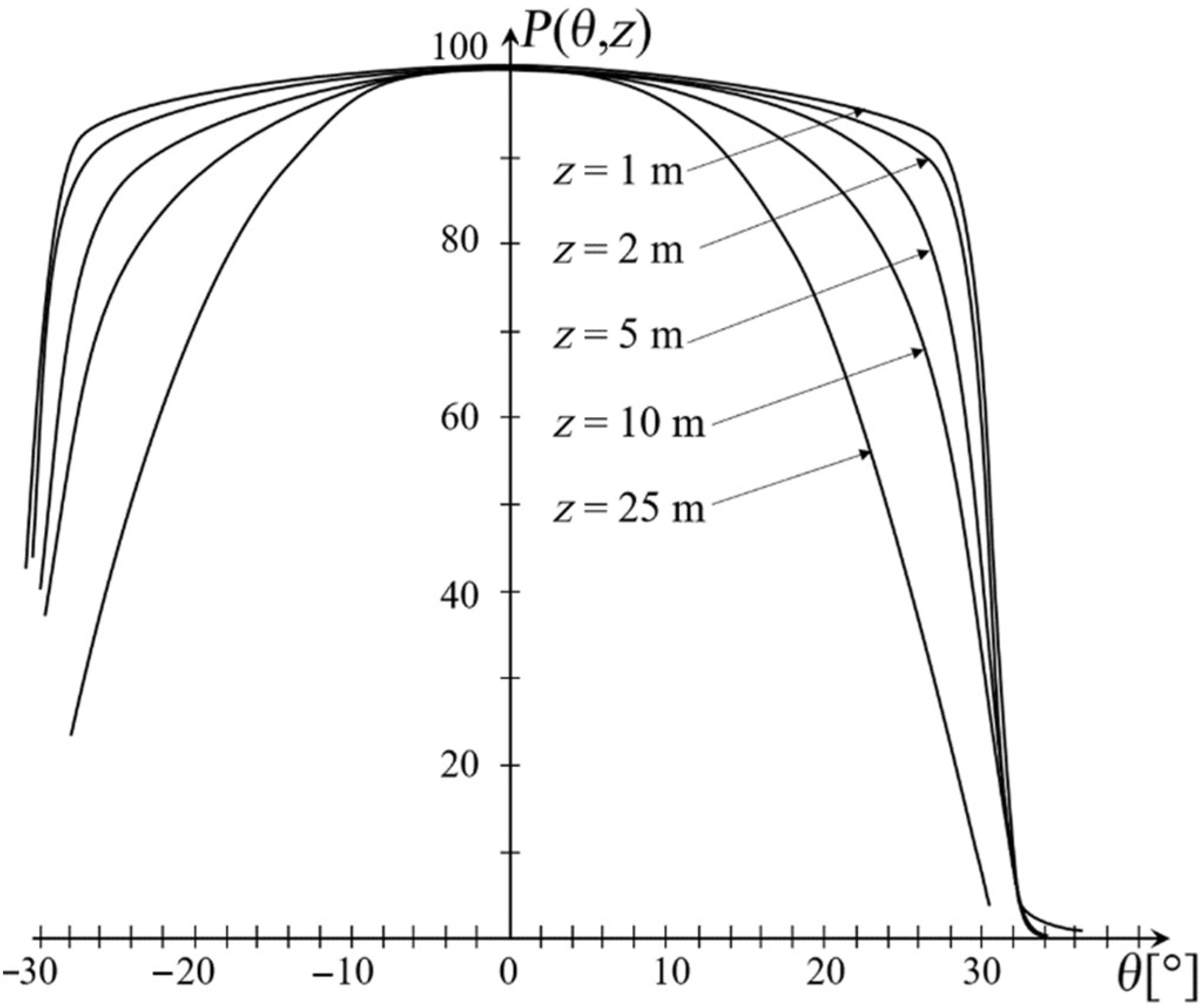
The inner critical angle of the CROFON fiber is 30.4°. Dugas et al. [15] employed a centrally launched beam that was broader than the SSD in their experiment (Figure 2). In order to calculate the coupling coefficient D, Equation (5) was employed. For the CROFON fiber, the standard deviation of the output angular power distribution P(θ,z) measured σ z 1 ≈ 27.5° and σ z 1 ≈ 22.5° at fiber lengths z1 = 10 m and z2 = 25 m, respectively (Figure 2).
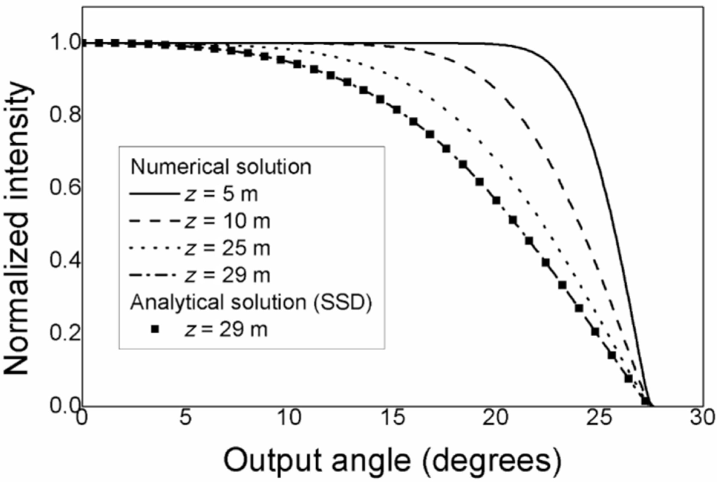
Using Equation (5), we found the coupling coefficient of D = 2.5 × 10 3   rad 2 / m . We used the calculated coupling coefficients D to obtain the length zs, at which SSD is reached in the CROFON fiber. The PFE (2) was solved numerically [14] in order to obtain the P(θ,z) at different fiber lengths z. Figure 3 depicts the circumstance in which a Gaussian distribution beam with (FWHM)z=0 = 58° was launched centrally along the axis of the CROFON fiber. Figure 3 illustrates the SSD obtained as an analytical Solution (3) of Equation (2) (squares), in addition to the normalized curves of the P(θ,z) produced as numerical solutions of Equation (2) (line graph), where γ0 = 0.0514 m−1 is used in the analytical Solution (3). With a relative error of less than 1%, these solutions are in good agreement. Due to modal diffusion, e.g., energy transfer between modes, with increasing fiber length the distribution narrows, as seen in Figure 3. In Figure 3, the SSD is reached at length zs = 29 m. The CROFON fiber’s coupling coefficient D = 2.5 × 10 3   rad 2 / m obtained in this work is comparable to that of standard SI PMMA fibers ( D 2.6 ÷ 9.8 × 10 4   rad 2 / m ) [16]. As a result, the CROFON fiber’s length zs = 29 m is of the same order of magnitude compared to that of typical SI PMMA fibers zs ≃ 40 to 100 m [16]. This is due to the similar strength of intrinsic perturbation effects in these two types of fibers (e.g., irregularities of the core-cladding interface, micro-bendings, refractive index fluctuations) despite the fact that they both have a PMMA core but distinct cladding. Plastic clad silica fibers (silica core) with characteristic lengths zs ≃ 1 to 3 km have been shown to have lesser perturbation effects (smaller D) than PMMA core fibers ( D ~ 10 6   to   10 5   rad 2 / m ) [17]. Optical fibers with a glass core and cladding have the least coupling coefficient D ~ 10 7   to   10 6   rad 2 / m and the weakest intrinsic perturbation effects [18]. Their typical lengths for obtaining the SSD range from zs ≃ 1 to 10 km. As illustration, Table 1 shows coupling coefficient D and lengths zs for SI OGC PMMA fiber investigated in this work, and SI PMMA fiber and silica fiber investigated in previous works [17,18]. It is evident that the fiber core material has a greater impact on the mode coupling in optical fibers than the cladding material. Due to the strong influence of mode coupling on the transmission in optical fibers, principal optical characteristics of an optical fiber cannot be accurately defined until SSD is not yet completely achieved. Furthermore, at lengths z > zs, the bandwidth becomes fully independent on the launch conditions [19]. It should be mentioned that bending, heating and etching increase mode coupling in optical fibers, which should be taken into account when employing a particular optical fiber as a part of communication and sensory system.
It is worth noting that our method for determining the coupling coefficient D, which we used in this work, has been successfully employed in the investigation of mode coupling in multimode SI glass optical fibers performed by Hurand et al. [18], SI PMMA fibers [16] and SI plastic-clad silica optical fibers, performed by Savović and Djordjevich [17]. In this work, we have demonstrated a successful employment of this method in the investigation of the mode coupling process in multimode SI OGC PMMA fiber.

5. Conclusions

We explored the influence of the mode coupling process on light transmission in multimode SI OGC PMMA fiber using the PFE. The coupling coefficient D in SI OGC PMMA fiber is determined in this study by employing our previously proposed method [14]. The coupling coefficient D = 2.5 × 10 3   rad 2 / m for the fiber under investigation is comparable to that of ordinary SI PMMA fibers. As a result, the SI OGC PMMA fiber’s length zs = 29 m is comparable to that of typical SI PMMA fibers zs ≃ 40 to 100 m. This is due to the similar level of perturbation effects in these two types of fibers, despite the fact that they both have a PMMA core but distinct cladding. Optical fibers with a plastic core experience higher perturbation effects and, as a result, show more intense mode coupling than those with a glass core, regardless of the cladding material. The observations concerning the propagation distances required to reach SSD are physically significant. It is worth noting that due to the strong influence of mode coupling on the transmission in optical fibers, principal optical characteristics of an optical fiber cannot be accurately defined until SSD is not yet completely achieved. Furthermore, at lengths z > zs, bandwidth becomes fully independent on the launch conditions. Since the most important feature of an optical fiber is its bandwidth, these results could be valuable in communication systems that employ SI OGC PMMA fiber. Finally, our method for determining the coupling coefficient D, which is used in this work, has been successfully employed in the previous investigation of mode coupling in multimode SI glass optical fibers, SI PMMA fibers and SI plastic-clad silica optical fibers.

Author Contributions

Methodology, software, S.S.; writing—original draft preparation, S.S., I.S. and R.M.; writing—review and editing, A.D., S.S. and R.M.; funding acquisition, S.S. and R.M. All authors have read and agreed to the published version of the manuscript.

Funding

This research was funded by the National Natural Science Foundation of China (62003046, 6211101138); the Strategic Research Grant of City University of Hong Kong (CityU 7004600); Serbian Ministry of Education, Science and Technological Development (451-03-68/2022-14/200122); Science Fund of the Republic Serbia (CTPCF-6379382); Guangdong Basic and Applied Basic Research Foundation (2021A1515011997); Special project in key field of Guangdong Provincial Department of Education (2021ZDZX1050); The Innovation Team Project of Guangdong Provincial Department of Education (2021KCXTD014).

Institutional Review Board Statement

Not applicable.

Informed Consent Statement

Not applicable.

Data Availability Statement

The data presented in this study are available on request from the corresponding authors.

Conflicts of Interest

The authors declare no conflict of interest.

References

  1. Zhou, J.; Yang, C.; Sui, Q.; Wang, H.; Feng, Y.; Liu, W.; Yan, Y.; Li, J.; Yu, C.; Li, Z. Burst-error-propagation suppression for decision-feedback equalizer in field-trial submarine fiber-optic communications. J. Lightwave Technol. 2021, 39, 4601–4606. [Google Scholar] [CrossRef]
  2. Anuszkiewicz, A.; Kasztelanic, R.; Filipkowski, A.; Stepniewski, G.; Stefaniuk, T.; Siwicki, B.; Pysz, D.; Klimczak, M.; Buczynski, R. Fused silica optical fibers with graded index nanostructured core. Sci. Rep. 2018, 8, 12329. [Google Scholar] [CrossRef] [PubMed]
  3. Ayesta, I.; Zubia, J.; Arrue, J.; Illarramendi, J.M.A.; Azkune, M. Characterization of chromatic dispersion and refractive index of polymer optical fibers. Polymers 2017, 9, 730. [Google Scholar] [CrossRef] [PubMed] [Green Version]
  4. Zubía, J.; Durana, G.; Aldabaldetreku, G.; Arrue, J.; Losada, M.A.; Lopez-Higuera, M. New method to calculate mode conversion coefficients in SI multimode optical fibers. J. Lightwave Technol. 2003, 21, 776–781. [Google Scholar] [CrossRef]
  5. Kobayashi, T.; Blau, W.J.; Tillmann, H.; Horhold, H.-H. Light amplification and lasing in a stilbenoid compound-doped glass-clad polymer optical fiber. IEEE J. Quant. Electron. 2003, 39, 664–672. [Google Scholar] [CrossRef]
  6. Apolo, J.; Ortega, B.; Almenar, V. Hybrid POF/VLC links based on a single LED for indoor communications. Photonics 2021, 8, 254. [Google Scholar] [CrossRef]
  7. Garito, A.F.; Wang, J.; Gao, R. Effects of random perturbations in plastic optical fibers. Science 1998, 281, 962–967. [Google Scholar] [CrossRef] [PubMed]
  8. Leal-Junior, A.; Frizera, A.; Marques, C.; José Pontes, M. Mechanical properties characterization of polymethyl methacrylate polymer optical fibers after thermal and chemical treatments. Opt. Fiber Technol. 2018, 43, 106–111. [Google Scholar] [CrossRef]
  9. Corrado, A.; Polini, W. Measurement of high flexibility components in composite material by touch probe and force sensing resistors. J. Manuf. Process. 2019, 45, 520–531. [Google Scholar] [CrossRef]
  10. Hao, M.; Li, H.; Cui, L.; Liu, W.; Fang, B.; Liang, J.; Xie, X.; Wang, D.; Wang, F. Higher photocatalytic removal of organic pollutants using pangolin-like composites made of 3–4 atomic layers of MoS2 nanosheets deposited on tourmaline. Environ. Chem. Lett. 2021, 19, 3573–3582. [Google Scholar] [CrossRef]
  11. Lustermann, B.; Quandt, B.M.; Ulrich, S.; Spano, F.; Rossi, R.M.; Boese, L.F. Experimental determination and ray-tracing simulation of bending losses in melt-spun polymer optical fibres. Sci. Rep. 2020, 10, 11885. [Google Scholar] [CrossRef] [PubMed]
  12. Gloge, D. Optical power flow in multimode fibers. Bell Syst. Tech. J. 1972, 51, 1767–1783. [Google Scholar] [CrossRef]
  13. Gambling, A.; Payne, D.P.; Matsumura, H. Mode conversion coefficients in optical fibers. Appl. Opt. 1975, 14, 1538–1542. [Google Scholar] [CrossRef] [PubMed]
  14. Savović, S.; Djordjevich, A. Method for calculating the coupling coefficient in step index optical fibers. Appl. Opt. 2007, 46, 1477–1481. [Google Scholar] [CrossRef] [PubMed]
  15. Dugas, J.; Sotom, M.; Martin, L.; Cariou, J.-M. Accurate characterization of the transmissivity of large diameter multimode optical fibers. Appl. Opt. 1987, 26, 4198–4208. [Google Scholar] [CrossRef] [PubMed]
  16. Savović, S.; Djordjevich, A. Mode coupling in strained and unstrained step-index plastic optical fibers. Appl. Opt. 2006, 45, 6775–6780. [Google Scholar] [CrossRef] [PubMed]
  17. Savović, S.; Djordjevich, A. Mode coupling and its influence on space division multiplexing in step-index plastic-clad silica fibers. Opt. Fiber Technol. 2018, 46, 92–197. [Google Scholar] [CrossRef]
  18. Hurand, S.; Chauny, L.-A.; El-Rabii, H.; Joshi, S.; Yalin, A. Mode coupling and output beam quality of 100–400 μm core silica fibers. Appl. Opt. 2011, 50, 492–499. [Google Scholar] [CrossRef] [PubMed]
  19. Savović, S.; Drljača, B.; Djordjevich, A. Influence of launch beam distribution on bandwidth in step index plastic optical fibers. Appl. Opt. 2013, 52, 1117–1121. [Google Scholar] [CrossRef] [PubMed]
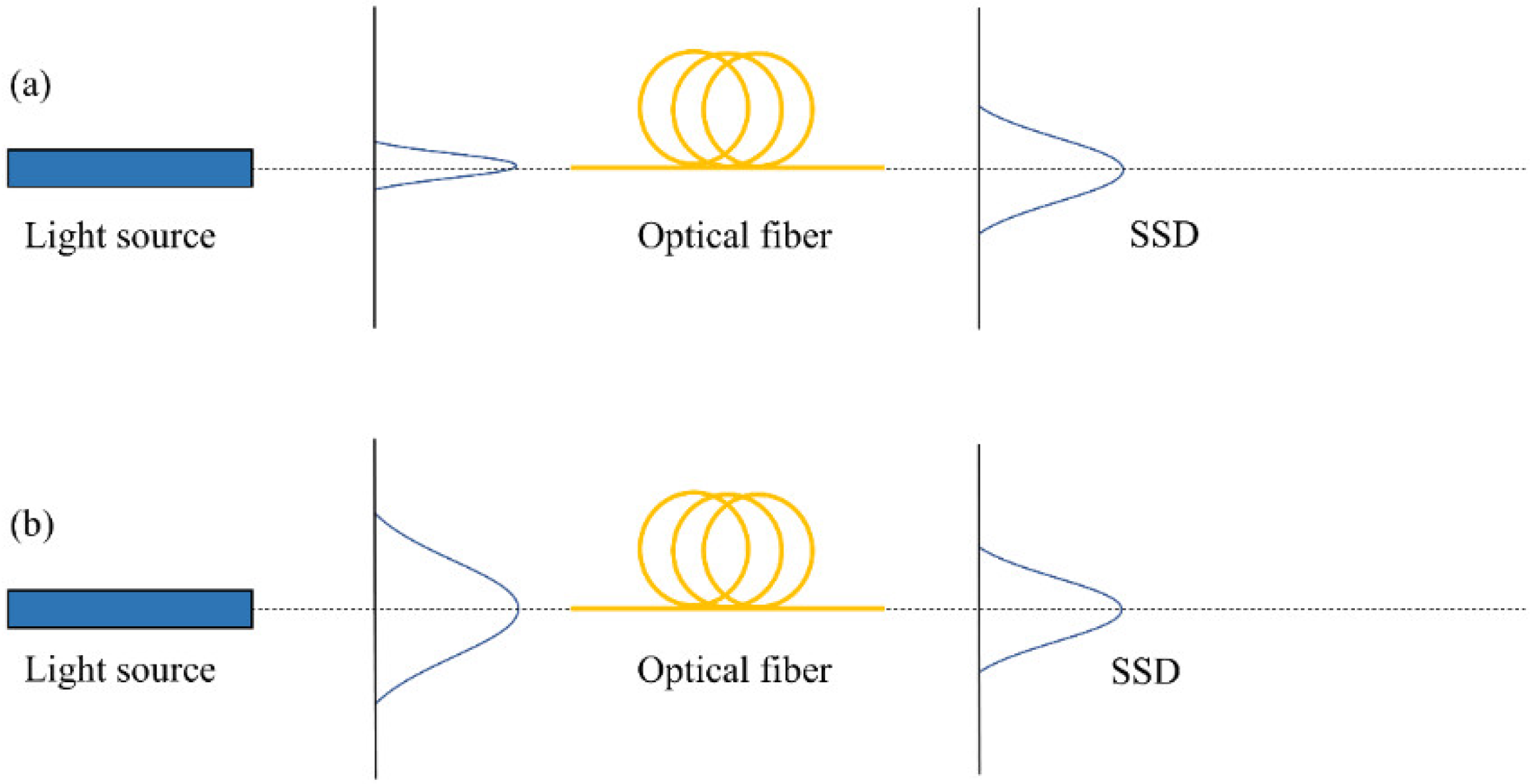
Figure 1. Sketch of the light beam centrally launched into optical fiber, where: (a) the input beam is narrower than the SSD; and (b) the input beam is wider than the SSD.
Photonics 09 00297 g001
Figure 2. Measured normalized P(θ,z) at different lengths of the CROFON fiber, in the case of central launch (θ0 = 0°) [15].
Photonics 09 00297 g002
Figure 3. Normalized P(θ,z) along the CROFON fiber numerically calculated for Gaussian launch distribution centered at θ0 = 0° with (FWHM)z=0 = 58°, at z = 5, 25 and 29 m (⯀ represent the analytical SSD, Equation (3)).
Photonics 09 00297 g003
Table 1. Core refractive index n0, critical angle θc, numerical aperture NA, coupling coefficient D, length zs at which SSD is achieved, for SI OGC PMMA fiber, SI PMMA fiber, SI plastic-clad silica fiber and SI silica fiber.
SI OGC PMMA Fiber
(This Work)
SI PMMA Fiber
(Ref. [16])
SI Plastic-Clad Silica Fiber
(Ref. [17])
SI Silica Fiber
(Ref. [18])
n01.48771.4921.4571.457
θc (deg)30.430.024.013.5
NA0.5060.50.40.22
D (rad2/m) 2.5 × 10 3 3.5 × 10 4 1.28 × 10 5 1.9 × 10 6
zs (m)299814002470
Publisher’s Note: MDPI stays neutral with regard to jurisdictional claims in published maps and institutional affiliations.