Article

Focusing of a Laser Beam Passed through a Moderately Scattering Medium Using Phase-Only Spatial Light Modulator

Institute of Geosphere Dynamics, Leninskiy Avenue 38, Bld. 1, Moscow 119334, Russia
*
Author to whom correspondence should be addressed.
Photonics 2022, 9(5), 296; https://doi.org/10.3390/photonics9050296
Submission received: 14 March 2022 / Revised: 8 April 2022 / Accepted: 19 April 2022 / Published: 27 April 2022
(This article belongs to the Special Issue Various Applications of Methods and Elements of Adaptive Optics)

Abstract

:
The rarely considered case of laser beam propagation and focusaing through the moderately scattering medium was researched. A phase-only spatial light modulator (SLM) with 1920×1080 pixel resolution was used to increase the efficiency of focusing of laser radiation propagated through the 5 mm layer of the scattering suspension of 1 µm polystyrene microbeads in distilled water with the concentration values ranging from 105 to 106 mm−3. A CCD camera with micro-objective was used to estimate the intensity distribution of the far-field focal spot. A Shack-Hartmann sensor was used to measure wavefront distortions. The conducted experimental research demonstrated the 8% increase in integral intensity and 16% decrease in diameter of the far-field focal spot due to the use of the SLM for laser beam focusing.

Graphical Abstract

1. Introduction

A medium is considered to be turbid or scattering if it has a pronounced optical inhomogeneity due to the presence of impurities of particles with a refractive index that differs from a medium one. Striking examples are atmospheric aerosol, haze, fog, sea water, clouds, biological tissues, etc. [1]. There are at least two reasons why the light beam loses energy while propagating through a turbid medium—absorption and scattering. If the medium absorbs light then the energy is lost, but if the medium scatters light, the energy is not lost, it is just redistributed in space. As a result, it does not allow efficiently focusing the beam on the target and also it makes the contours of objects look blurred. Obviously, this is an obstacle for such applications as pattern recognition, wireless data transmission, medical noninvasive diagnosis, and some others [2,3,4,5,6,7,8].
A number of techniques were developed to overcome the problem of imaging and focusing through a scattering medium [5,6]. Clear images of an object could be obtained using holographic techniques by reversing a scattering process [9]. The technique called multispectral multiple-scattering low-coherence interferometry [10] uses coherence and spatial gating to produce images of optical properties of a tissue up to 9 mm deep with millimeter-scale resolution. When there is no access to the space behind a scattering layer, a non-invasive approach to image fluorescent objects can be used [11]. In order to focus light or to reconstruct images of an object placed within or behind a strongly scattering medium, spatial light modulators are often used [7,8,12,13]. In [14], authors demonstrated steady-state focusing of coherent light through dynamic scattering media. In [15], authors demonstrated numerically and experimentally that by using a transmission matrix inversion method peak-to-background intensity ratio of the focus can be higher than that achieved by conventional methods. The authors of [16] developed the new optical time-reversal focusing technique, called time reversal by analysis of changing wavefronts from kinetic targets, that allowed obtaining a focal peak-to-background strength of 204. In [17], authors developed the first full-polarization digital optical phase conjugation system that, on average, doubles the focal peak-to-background ratio achieved by single-polarization digital optical phase conjugation systems. The authors of [18] introduced a phase control technique using programmable acoustic optic deflectors to image the objects in dynamically changing living biological tissue. However, spatial light modulators are widely used in different areas of research; their use is not limited to the imaging and focusing applications only. Spatial light modulators also show vast potential in such applications as micro- and nano-scale fabrication [19].
On the one hand, the radiation wavefront could in principle be correctly measured and optimized with the help of conventional adaptive optics techniques [20,21,22,23,24,25,26,27] in case of the smooth and continuous change of the refractive index of the turbid medium. On the other hand, the radiation wavefront is completely scrambled in case of the scattering medium with random inhomogeneities of high concentration (i.e., biological tissues), and in this special case the wavefront shaping technique could be applied [28].
In other words, there are two regimes that can be distinguished. One regime is when the refractive index of an inhomogeneous medium changes smoothly and continuously in space (optical density value is less than 1). The other regime is when the medium has high concentration of random inhomogeneities (optical density value is higher than 10). The regimes mentioned above can be considered as different ends of a continuum [29], and most of the existing research is dedicated to these particular regimes.
In contrast, in this particular paper we would like to talk about the crossover regime [20]. In this regime we could measure the so-called averaged wavefront (that is not completely scrambled yet) of partially coherent light that has passed through the scattering layer, and we could try to apply the techniques of conventional adaptive optics to improve laser beam focusing (Figure 1).
The uniqueness of the crossover regime is that the focal spot obtained on the imaging sensor plane preserves its spatial structure despite huge energy loss due to scattering. The importance of researching the impact of the scattering effect on the light characteristics in the crossover regime can be explained by the fact that the scattering of the optical inhomogeneities prevents effective wireless energy/information transmission through the moderately scattering media (i.e., atmospheric aerosol, top layers of biological tissue). There are plenty of applications, both imaging and focusing, that will benefit from solving this particular problem—identification of objects in the atmosphere and under the water, increase of visibility of signaling lights of air strips, optical coherence and diffusive tomography, increase of efficiency of free-space optical communication systems, energy transmission to hard-to-reach objects, charging of unnamed aerial vehicles, diagnosis of malignant tissues, monitoring of drug impacts.
The main idea of our work was to control the direction of propagation of scattered (non-ballistic) light in order to improve the efficiency of light focusing [21,22]. Actually, the goal was to decrease the size and increase the energy inside the far-field focal spot obtained in the focal plane of the lens.
To achieve this, we developed a model based on the Shack-Hartmann technique to estimate the distortions of the averaged wavefront of the scattered laser beam and confirmed the simulation results experimentally; we assembled the experimental setup for laser beam focusing through the scattering suspension of polystyrene microspheres, and demonstrated the focusing enhancement.

2. Materials and Methods

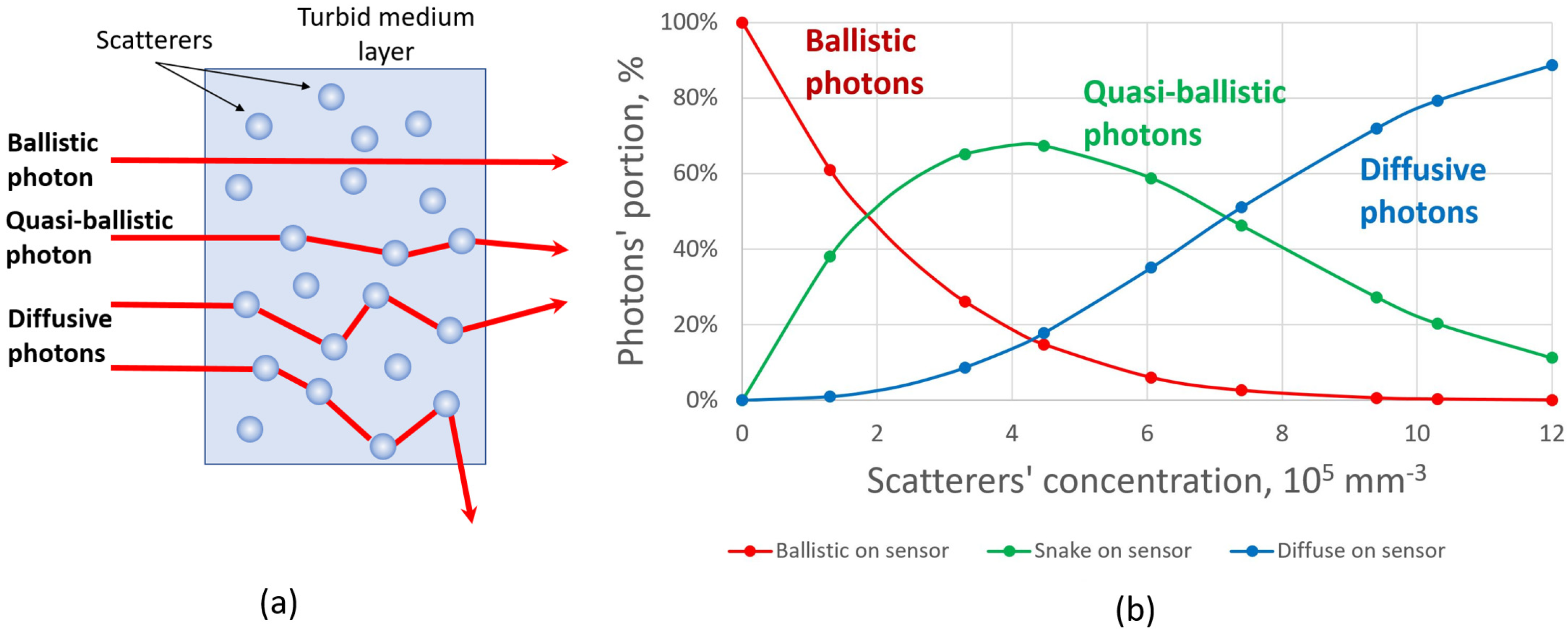
2.1. Monte Carlo Simulation of Radiation Transfer through a Scattering Medium

Prior to experimental research on how to minimize the effect of scattering on the quality of a focal spot, we performed a set of numerical simulations. First of all, we simulated the laser beam propagation through a scattering medium that is generally described by the radiative transfer equation [30]. From the wide variety of methods to solve this equation [31], we decided to use the stochastic Monte Carlo technique [32]. For the problem of light propagation, Monte Carlo technique takes into account the quantum nature of light and simulates the behavior of a photon flux [33].
There are three components of a scattered photon flux [34]. Ballistic photons travel through a turbid medium without interaction with the scatterers and do not change the initial trajectory. Quasi-ballistic photons undergo few scattering events and travel in near-forward paths along a trajectory that is close to the initial direction of the beam propagation. These photons play an important role in imaging and focusing when the thickness of the scattering medium layer increases, because the number of ballistic photons decreases exponentially in this case. Diffusive photons scatter in all directions and form a noncoherent component of the scattered light (Figure 2a). Based on the Monte Carlo simulation performed [35,36], we found that there is a big portion of quasi-ballistic photons that passes through the turbid medium and reaches the detector plane (Figure 2b).
A big portion of quasi-ballistic photons can be explained by the anisotropic Mie scattering which takes place for the considered scatterers’ concentration values (the crossover regime). The idea was to adjust the direction of this quasi-ballistic component by correcting for the overall direction diagram of the scattered beam by means of adaptive optics. In order to do that, it was necessary to find out the influence of the scattering medium on the characteristics of the laser beam. For this, we used the Shack-Hartmann principle [37].

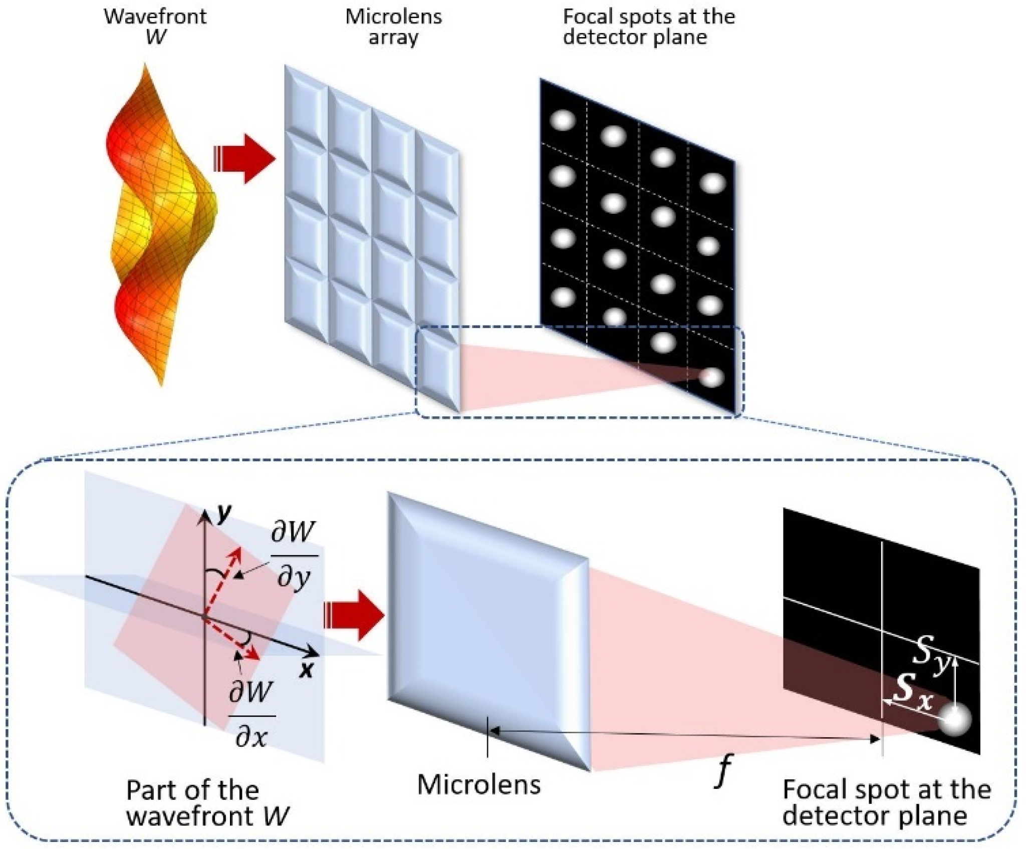
2.2. Shack-Hartmann Principle and Averaged Wavefront Concept

Shack-Hartmann principle consists in dividing the wavefront into a large number of small sub-apertures using a microlens array and measuring the displacements of focal spots in the detector plane. The spot displacement is proportional to the slope of the wavefront at the microlens aperture (Figure 3). Thus, by measuring the spot displacements and calculating the values of the derivatives of the polynomials used (Zernike, B-spline [38], etc.—in this paper we used Zernike), we can calculate the coefficients of the polynomials, which then can be used to approximate the wavefront.
Usually, the Shack-Hartmann sensor measures the wavefront of the light, but a laser beam that is passed through the scattering medium in the strict physical sense does not have a wavefront, since part of the radiation is scattered. Initially, before the scattering medium, the beam has a plane wavefront. The scatterers inside the medium that interacts with the radiation become the sources of new spherical waves with their own wave vectors. At the same time, part of the radiation passes through the medium without scattering, keeping the original flat wavefront. As a result, a focal spot is formed at the focal plane of the microlens. The displacement of this focal spot from the optical axis of the microlens is proportional to the local slope of a so-called averaged wavefront. Basically, this averaged wavefront is just a superposition of independent wavefronts from the scatterers and the wavefront of unscattered radiation passed through the medium.
In other words, the averaged wavefront is the superposition of the independent wavefronts coming from each scatterer that acts as a point source (quasi-ballistic and diffusive components) and the wavefront of unscattered (ballistic component) light. This method of measuring the averaged wavefront was implemented in the numerical model [39]. The photons passed through the medium, fell on the aperture of the simulated microlens array and retraced to the receiver plane (geometrical optics approach), forming a set of focal spots called a hartmannogram.
In each sub-aperture (that corresponds to the particular microlens) of the receiver plane, a single focal spot was registered during simulation. The intensity distribution of each focal spot depended on the number of photons registered inside each sub-aperture. The example of the resultant simulated field of focal spots is presented in Figure 4b. The inner blue circle corresponds to the initial diameter of the collimated beam before entering the scattering volume. The outer blue circle corresponds to the area of the Shack-Hartmann sensor where the averaged wavefront was analyzed.
To verify the model, an experimental setup was assembled with a diode laser, a suspension of polystyrene microbeads, and Shack-Hartmann sensor (1/2-inch sensor with the size of the receiving area equal to 6.4 × 4.8 mm, focal length of the microlens array—6 mm, diameter of a single microlens—150 µm, total number of microlenses—greater than 1300). An analysis of the hartmannograms obtained numerically and experimentally showed that the displacements of the focal spots in the central part of the beam were rather small due to the influence of ballistic photons in this area. However, scattering led to the appearance of peripheral focal spots on the sensor outside the diameter of the initial beam, and they were predominantly displaced from the center (Figure 4b). The typical 3D view of the averaged wavefront reconstructed by means of Zernike polynomials is presented in Figure 4c. We obtained such a surface for each of the considered concentration values, and the only difference between these surfaces was an amplitude —the shape of the surface was the same.
A typical view of averaged wavefront surfaces approximated by Zernike polynomials is shown in Figure 4c. The surfaces for different values of the concentration looks very similar and differs only in amplitudes. Since the Mie scattering by spherical particles has a symmetric nature, the distortions were also represented only by centrally symmetric Zernike polynomials. What is important is that in addition to defocus (Zernike polynomial # 3), higher-order spherical distortions were also observed (Figure 4a). Moreover, with an increase in concentration, the amplitude of distortions increased. The tendency towards an increase in the total amplitude of distortions with increasing concentration persisted both in the model and in the experiment [39].
It can be clearly seen that with an increase in the concentration of scatterers, the energy redistribution in the beam as well as the amplitude of the averaged wavefront also increases. As is known, one of the possible ways to control the intensity distribution is to use adaptive optical devices—either deformable mirrors or spatial light modulators [40,41,42]. The results of the successful use of deformable mirrors based on a bimorph piezoelectric element to improve focusing of a laser beam passed through the moderately scattering medium are presented in [39]. In this paper, we would like to show the results obtained in the similar experimental setup but with the use of a phase-only spatial light modulator.

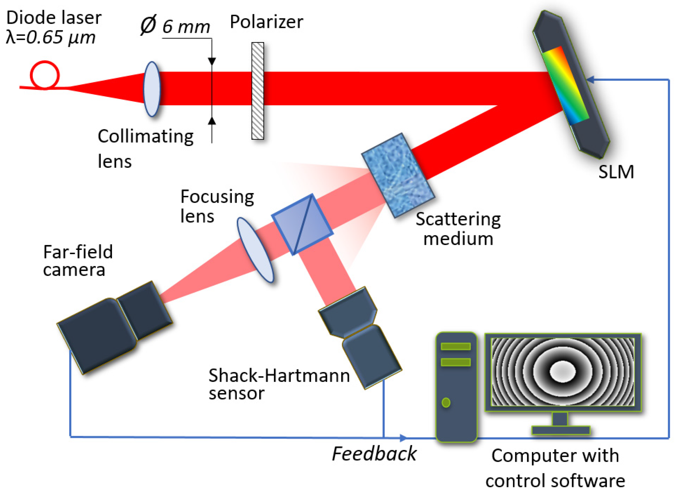
2.3. Experimental Scheme

The experimental setup for measuring the averaged wavefront distortions and focusing a scattered laser beam was assembled. The scheme of this setup is presented in Figure 5.
A collimated laser beam (wavelength 0.65 µm) of 6 mm diameter propagated through the polarizer, reflected from the SLM and fell on the transparent 5 mm-thick glass cuvette filled with the polystyrene microbeads of 1 μm diameter diluted in distilled water. The scattered beam fell on the beam-splitter. Part of the beam was directed to the Shack-Hartmann sensor to measure the averaged wavefront. Another part of the beam was focused on the CCD camera with the micro-objective to analyze the intensity distribution of the focal spot. The camera provided image data to the computer. We used the reflective SLM made by Jasper Display Corp. (1920 × 1080 pixels, 12.5 × 7.1 mm active area). It operated in an 8-bit regime. The Shack-Hartmann sensor was based on the CMOS ½” camera and in this setup was used for measurement purposes only. The CCD camera with ½” sensor was used as an intensity analyzer.
The flow map of the algorithm that we used for laser beam focusing by means of SLM is presented in Figure 6.
As was shown in previous research [39], low- and high-order axial-symmetric distortions predominated in the averaged wavefront of scattered light. Thus, we decided to operate the SLM using a “phase screen” approach. Instead of controlling each pixel of the SLM individually, we calculated the whole phase surface phase(x,y) of the particular Zernike polynomial and then calculated the phase pattern φ(x,y) using the formula (1) to be sent to the SLM:
φ(x,y) = 255 ∙ remainder(phase(x,y)/λ),
where remainder is a reminder of division, phase(x,y) is the phase value at a particular point (X,Y) and λ is the wavelength. The calculated phase pattern was then sent to the SLM. The merit function was calculated after the SLM was settled. In cases where the merit function became better, the current Zernike coefficient was increased by the fixed step (0.015 µm). The whole calculation cycle was run again. In cases where the merit function became worse, the Zernike coefficient was rolled back to the previous value and then decreased. Then the calculation cycle was run again. When the merit function became worse, the best value of the current Zernike coefficient was saved and the algorithm was moved to the next Zernike coefficient and the procedure was repeated. In such a way we improved the merit function step by step. We used the hill-climbing optimization technique; the total number of Zernike polynomials was 36 in this experiment. We used the combination of diameters (Dx, Dy) and peak intensity (Imax) of the far-field focal spot as a merit function M = max(Dx, Dy) · (Dx + Dy)/Imax.

3. Results and Discussion

Before conducting experiments with the scattering medium, we calibrated the setup. We placed the glass cuvette with the distilled water only (without the polystyrene microbeads) in the optical path and ran the optimization procedure in order to compensate for the induced distortions. We considered the far-field focal spot obtained after optimization as the best achievable focal spot for this experimental setup. In such a way, we took into account all of the misalignments and imperfections of the optical elements of the set-up. After that we measured only the distortions of the laser beam induced by the scattering particles.
After the calibration was done, we started to inject the drops of the scattering dispersion into the cuvette one by one. For each considered concentration of the scattering solution—3.1 × 105 mm−3, 5.1 × 105 mm−3, 6.8 × 105 mm−3, and 8.2 × 105 mm−3—we obtained intensity distributions of the far-field focal spot and corresponding SLM patterns before and after optimization. We also calculated the encircled energy. Figure 7 presents the results of measurements for the minimal (3.1 × 105 mm−3) and maximal (8.2 × 105 mm−3) concentration values considered in this work.
The integral intensity of the focal spot obtained on the imaging sensor when no scattering medium was introduced in the setup was considered as 100%. Then the integral intensities of the focal spots before and after optimization procedure were as follows: 95.7% (before) and 97.7% (after) for the concentration value 3.1 × 105 mm−3, 93.8% and 96.6% for the concentration value 5.1 × 105 mm−3, 85.1% and 91.9% for the concentration value 6.8 × 105 mm−3, 74.3% and 82.2% for the concentration value 8.2 × 105 mm−3. The increase in optimization E was equal to 2.1%, 3%, 8%, and 11%, and was calculated as follows:
E = (IafterIbefore)/Ibefore × 100%,
where Ibefore—integral intensity before optimization, Iafter—integral intensity of the focal spot after optimization.
The diameters of the focal spots were reduced by 5.2%, 9.7%, 16.4%, and 13.2% during the optimization process, correspondingly.
We note that the decrease of the focal spot diameter for the concentration value of 6.8 × 105 mm−3 is lower than the one for the concentration value of 8.2 × 105 mm−3 (16.4% versus 13.2%). This is due to the impact of multiply scattered diffuse light. Figure 2b clearly shows that the number of diffuse photons becomes higher than the number of quasi-ballistic and ballistic photons since the concentration value becomes higher than 8 × 105 mm−3. In other words, the integral intensity in the focal spot can become higher due to the optimization, but the diameter of the focal spot is decreasing more slowly because a diffuse light unavoidably broadens the focal spot.
The efficiency of focusing is much higher for the higher concentration value. This is due to the fact that the higher the concentration of scattering medium, the higher the portion of scattered light that can be redirected to the central part of the focal spot using the SLM.
Note that none of the dashed curves in Figure 7 (when the SLM was on) could approach the black solid curve: this is due to energy loss during the scattering process. Part of the scattered laser beam simply did not reach the objective of the imaging camera.

4. Conclusions

In this paper we have demonstrated the use of a phase-only spatial light modulator (SLM) with 1920 × 1080 pixels resolution for increasing the efficiency of focusing of laser radiation propagated through the moderately scattering medium—5 mm layer of 1 µm polystyrene microbeads diluted in distilled water with concentration values ranging from 105 to 106 mm−3. We have presented the concept of the averaged wavefront that is the superposition of the independent wavefronts coming from each scatterer that acts as a point source (quasi-ballistic and diffusive components) and the wavefront of unscattered (ballistic component) light. We have demonstrated numerically and experimentally the efficiency of a Shack-Hartmann sensor to measure the averaged wavefront. Experimental research also demonstrated that the SLM allows an increase in the efficiency of laser beam focusing up to 2.1%, 3%, 8%, and 11%, and a decrease in the diameter of the focal spot by 5.2%, 9.7%, 16.4%, and 13.2% for the scatterers’ concentration range 105 to 106 mm−3. Although the increase of focusing efficiency is only up to 11%, it should be noted that we used the phase screen approach during the optimization procedure. Basically, we calculated the phase surface that corresponded to the particular Zernike polynomial and then set it to the SLM rather than controlling each pixel of the SLM individually and one by one (this single pixel approach is rather popular and vastly described in the literature). The advantage of the phase screen approach is a significant increase in optimization speed, the disadvantage is of course lower efficiency. Thus, depending on the problem to be solved one can choose one approach or another. Moreover, promising results can be obtained by combining these approaches.

Author Contributions

Conceptualization, I.G. and A.K.; methodology, I.G., A.N. and A.K.; software, I.G.; validation, A.N., J.S. and I.G.; formal analysis, A.N.; investigation, I.G.; resources, J.S. and V.T.; data curation, A.K.; writing—original draft preparation, I.G.; writing—review and editing, J.S., A.K., V.T. and I.G.; visualization, I.G.; supervision, A.K.; project administration, A.K.; funding acquisition, A.K. All authors have read and agreed to the published version of the manuscript.

Funding

The research was carried out (1) within the state assignment of Ministry of Science and Higher Education of the Russian Federation No. 1021052706254-7-1.5.4—research of laser beam propagation through a scattering medium; (2) within the Russian Science Foundation project # 20-69-46064—research of adaptive optical system control by means of wavefront sensor and intensity analyzer.

Data Availability Statement

The data presented in this study are partially available in [39].

Conflicts of Interest

The authors declare no conflict of interest.

References

  1. van de Hulst, H.C. Light Scattering by Small Particles; John Wiley & Sons, Inc.: New York, NY, USA, 1957. [Google Scholar]
  2. Mosk, A.P.; Lagendijk, A.; Lerosey, G.; Fink, M. Controlling waves in space and time for imaging and focusing in complex media. Nat. Photonics 2012, 6, 283. [Google Scholar] [CrossRef] [Green Version]
  3. Bashkatov, A.N.; Priezzhev, A.V.; Tuchin, V.V. Laser technologies in biophotonics. Quantum Electron. 2012, 42, 379. [Google Scholar] [CrossRef]
  4. Mastiani, B.; Vellekoop, I.M. Noise-tolerant wavefront shaping in a Hadamard basis. Optics Express. 2021, 29, 2309. [Google Scholar] [CrossRef] [PubMed]
  5. Zhang, Y.; Chen, Y.; Yu, Y.; Xue, X.; Tuchin, V.V.; Zhu, D. Visible and near-infrared spectroscopy for distinguishing malignant tumor tissue from benign tumor and normal breast tissues in vitro. J. Biomed. Opt. 2013, 18, 077003. [Google Scholar] [CrossRef] [PubMed] [Green Version]
  6. Goodman, J.W.; Huntley, W.H., Jr.; Jackson, D.W.; Lehmann, M. Wavefront reconstruction imaging through random media. Appl. Phys. Lett. 1966, 8, 311–313. [Google Scholar] [CrossRef]
  7. Katz, O.; Small, E.; Silberberg, Y. Looking around corners and through thin turbid layers in real time with scattered incoherent light. Nat. Photon. 2012, 6, 549–553. [Google Scholar] [CrossRef]
  8. Popoff, S.M.; Lerosey, G.; Carminati, R.; Fink, M.; Boccara, A.C.; Gigan, S. Measuring the transmission matrix in optics: An approach to the study and control of light propagation in disordered media. Phys. Rev. Lett. 2010, 104, 100601. [Google Scholar] [CrossRef]
  9. Kogelnik, H.; Pennington, K.S. Holographic imaging through a random medium. J. Opt. Soc. Am. 1968, 58, 273–274. [Google Scholar] [CrossRef]
  10. Matthews, T.; Medina, M.; Maher, J.; Levinson, H.; Brown, W.; Wax, A. Deep tissue imaging using spectroscopic analysis of multiply scattered light. Optica 2014, 1, 105. [Google Scholar] [CrossRef]
  11. Bertolotti, J.; van Putten, E.G.; Blum, C.; Lagendijk, A.; Vos, W.L.; Mosk, A.P. Non-invasive imaging through opaque scattering layers. Nature 2012, 491, 232–234. [Google Scholar] [CrossRef]
  12. Conkey, D.B.; Caravaca-Aguirre, A.M.; Piestun, R. High-speed scattering medium characterization with application to focusing light through turbid media. Opt. Express 2012, 20, 1733–1740. [Google Scholar] [CrossRef] [PubMed]
  13. Hsieh, C.; Pu, Y.; Grange, R.; Laporte, G.; Psaltis, D. Imaging through turbid layers by scanning the phase conjugated second harmonic radiation from a nanoparticle. Opt. Express 2010, 18, 20723–20731. [Google Scholar] [CrossRef] [PubMed] [Green Version]
  14. Stockbridge, C.; Lu, Y.; Moore, J.; Hoffman, S.; Paxman, R.; Toussaint, K.; Bifano, T. Focusing through dynamic scattering media. Opt. Express 2012, 20, 15086–15092. [Google Scholar] [CrossRef] [PubMed]
  15. Xu, J.; Ruan, H.; Liu, Y.; Zhou, H.; Yang, C. Focusing light through scattering media by transmission matrix inversion. Opt. Express 2017, 25, 27234–27246. [Google Scholar] [CrossRef]
  16. Zhou, E.H.; Ruan, H.; Yang, C.; Judkewitz, B. Focusing on moving targets through scattering samples. Optica 2014, 1, 227–232. [Google Scholar] [CrossRef] [Green Version]
  17. Shen, Y.; Liu, Y.; Ma, C.; Wang, L.V. Focusing light through scattering media by full-polarization digital optical phase conjugation. Opt. Lett. 2016, 41, 1130–1133. [Google Scholar] [CrossRef] [Green Version]
  18. Feldkhun, D.; Tzang, O.; Wagner, K.H.; Piestun, R. Focusing and scanning through scattering media in microseconds. Optica 2019, 6, 72–75. [Google Scholar] [CrossRef]
  19. Li, R.; Jin, D.; Pan, D.; Ji, S.; Xin, C.; Liu, G.; Fan, S.; Wu, H.; Li, J.; Hu, Y.; et al. Stimuli-Responsive Actuator Fabricated by Dynamic Asymmetric Femtosecond Bessel Beam for In Situ Particle and Cell Manipulation. ACS Nano 2020, 14, 5233–5242. [Google Scholar] [CrossRef]
  20. Barchers, J.D.; Fried, D.L. Optimal control of laser beams for propagation through a turbulent medium. JOSA A 2002, 19, 1779–1793. [Google Scholar] [CrossRef]
  21. Galaktionov, I.; Kudryashov, A.; Sheldakova, J.; Nikitin, A. Laser beam focusing through the dense multiple scattering suspension using bimorph mirror. Proc. SPIE 2019, 10886, 1088619. [Google Scholar]
  22. Galaktionov, I.; Kudryashov, A.; Sheldakova, J.; Nikitin, A.; Samarkin, V. Laser beam focusing through the atmosphere aerosol. Proc. SPIE 2017, 10410, 104100M. [Google Scholar]
  23. Chamot, S.R.; Dainty, C.; Esposito, S. Adaptive optics for ophthalmic applications using a pyramid wavefront sensor. Optics Express 2006, 14, 518–526. [Google Scholar] [CrossRef] [PubMed]
  24. Roddier, F.J.; Anuskiewicz, J.; Graves, J.; Northcott, M.J.; Roddier, C.A. Adaptive optics at the University of Hawaii I: Current performance at the telescope. Proc. SPIE 1994, 2201, 2–9. [Google Scholar]
  25. Konyaev, P.A.; Lukin, V.P.; Gorbunov, I.A.; Kulagin, O.V. Hybrid adaptive optical system correcting turbulent distortions on the long atmospheric paths. Proc. SPIE 2021, 11860, 16–26. [Google Scholar]
  26. Sheldakova, J.; Rukosuev, A.; Alexandrov, A.; Kudryashov, A. Multy-dither adaptive optical system for laser beam control. Proc. SPIE 2003, 4969, 115–121. [Google Scholar]
  27. Kudryashov, A.; Rukosuev, A.; Samarkin, V.; Galaktionov, I. Fast adaptive optical system for 1.5 km horizontal beam propagation. Proc. SPIE 2018, 10772, 107720V. [Google Scholar]
  28. Vellekoop, I.M.; Mosk, A.P. Focusing coherent light through opaque strongly scattering media. Opt. Lett. 2007, 32, 2309–2311. [Google Scholar] [CrossRef]
  29. Vellekoop, I.M. Feedback-based wavefront shaping. Opt. Express 2015, 23, 12189–12206. [Google Scholar] [CrossRef]
  30. Berrocal, E.; Sedarsky, D.; Paciaroni, M.; Meglinski, I.; Linne, M. Laser light scattering in turbid media Part I: Experimental and simulated results for the spatial intensity distribution. Opt. Express 2007, 15, 10649–10665. [Google Scholar] [CrossRef]
  31. Vorob’eva, E.A.; Gurov, I.P. Models of Propagation and Scattering of Optical Radiation in Randomly Inhomogeneous Media; Moscow Meditsina: Moscow, Russia, 2006. [Google Scholar]
  32. Wang, L.; Jacques, S. MCML—Monte Carlo modeling of light transport in multi-layered tissues. Comput. Programs Methods Biomed. 1995, 47, 131. [Google Scholar] [CrossRef]
  33. Meglinski, I.V. Quantitative assessment of skin layers absorption and skin reflectance spectra simulation in the visible and near-infrared spectral regions. Physiol. Meas. 2002, 23, 741. [Google Scholar] [CrossRef] [PubMed]
  34. Ramachandran, H. Imaging through turbid media. Curr. Sci. 1999, 76, 1334. [Google Scholar]
  35. Galaktionov, I.V.; Kudryashov, A.V.; Sheldakova, Y.V.; Byalko, A.A.; Borsoni, G. Measurement and correction of the wavefront of the laser light in a turbid medium. Quantum Electron. 2017, 47, 32–37. [Google Scholar] [CrossRef]
  36. Galaktionov, I.; Kudryashov, A.; Sheldakova, J.; Nikitin, A.; Samarkin, V. Laser beam focusing through the scattering medium by means of adaptive optics. Proc. SPIE 2017, 10073, 100731L. [Google Scholar]
  37. Nikitin, A.; Galaktionov, I.; Denisov, D.; Karasik, V.; Sakharov, A.; Baryshnikov, N.; Sheldakova, J.; Kudryashov, A. Absolute calibration of a Shack-Hartmann wavefront sensor for measurements of wavefronts. Proc. SPIE 2019, 10925, 109250K. [Google Scholar]
  38. Galaktionov, I.; Nikitin, A.; Sheldakova, J.; Kudryashov, A. B-spline approximation of a wavefront measured by Shack-Hartmann sensor. Proc. SPIE 2021, 11818, 118180N. [Google Scholar]
  39. Galaktionov, I.; Sheldakova, J.; Nikitin, A.; Samarkin, V.; Parfenov, V.; Kudryashov, A. Laser beam focusing through a moderately scattering medium using bimorph mirror. Opt. Express 2020, 28, 38061–38075. [Google Scholar] [CrossRef]
  40. Galaktionov, I.; Kudryashov, A.; Sheldakova, J.; Nikitin, A. Laser beam focusing through the scattering medium using bimorph deformable mirror and spatial light modulator. Proc. SPIE 2019, 11135, 111350B. [Google Scholar]
  41. Sheldakova, J.; Galaktionov, I.; Nikitin, A.; Rukosuev, A.; Kudryashov, A. LC phase modulator vs deformable mirror for laser beam shaping: What is better? Proc. SPIE 2018, 10774, 107740S. [Google Scholar]
  42. Sheldakova, J.; Toporovsky, V.; Galaktionov, I.; Nikitin, A.; Rukosuev, A.; Samarkin, V.; Kudryashov, A. Flat-top beam formation with miniature bimorph deformable mirror. Proc. SPIE 2020, 11486, 114860E. [Google Scholar]
Figure 1. Intensity distributions of the focal spot at the camera sensor placed at the focal plane of a focusing lens for different optical density values of the medium: (a) Wavefront shaping regime (image adapted from I. Vellekoop, Optics Letters 32(16), 2007); (b) crossover regime; (c) conventional adaptive optics regime (image adapted with permission from J. Sheldakova et.al., Proc. SPIE 4969, 2003).
Photonics 09 00296 g001
Figure 2. (a) Schematic trajectories of photons propagating through a scattering medium: ballistic, quasi-ballistic, and diffusive photons. (b) Number of photons reaching the sensor for the scatterers’ concentration range from 105 to 106 mm−3 (numerical simulation results).
Photonics 09 00296 g002
Figure 3. Principle of Shack-Hartmann technique—calculation of wavefront slopes based on focal spots displacements.
Photonics 09 00296 g003
Figure 4. (a) Dependence of Zernike coefficients of symmetric distortions (defocus and spherical aberrations) on the concentration value. (b) Simulated hartmannogram. White dots are focal spots generated by the photons that passed through the scattering medium, fell on the microlens array and were registered on the sensor plane. Inner blue circle shows the initial beam diameter (before it enters the scattering medium), outer blue circle shows the region where new focal spots appear due to the beam scattering. (c) A typical view of the surface of the averaged wavefront. PV (“peak-to-valley”) parameter shows an amplitude of averaged wavefront distortions.
Photonics 09 00296 g004
Figure 5. Scheme of the experimental setup with the SLM for laser beam focusing through a scattering medium.
Photonics 09 00296 g005
Figure 6. Flow map of the algorithm used to focus a scattered laser beam with the spatial light modulator.
Photonics 09 00296 g006
Figure 7. (a) Intensity distribution of the far-field focal spot obtained after the calibration procedure was done (glass cuvette contained water only). (b,c) Intensity distributions after optimization by means of the SLM for the concentration values 3.1 × 105 mm−3 and 8.2 × 105 mm−3, correspondingly. (df) SLM patterns that were used to obtain intensity distributions of focal spots presented above. (g) Normalized encircled energy charts: black solid curve—without scattering medium; blue curves—with scattering medium with concentration value 3.1 × 105 mm−3 before (solid curve) and after (dashed curve) focusing with the SLM; orange curves—with scattering medium with concentration value 8.2 × 105 mm−3 before (solid curve) and after (dashed curve) focusing with the SLM.
Photonics 09 00296 g007
Publisher’s Note: MDPI stays neutral with regard to jurisdictional claims in published maps and institutional affiliations.

