Abstract
A unique photonic crystal fiber with square and circular air holes (SC-PCF) is designed in this research. Three layers of circular air holes and two levels of square air holes make up the fiber cladding. The finite element approach is used to simulate the fiber construction, and numerical calculations are used to examine the transmission properties in the S+C+L band. The results reveal that the SC-PCF can sustain 86 Orbital Angular Momentum (OAM) modes in the wavelength range of 1400 nm to 1700 nm (300 nm), with an effective refractive index difference (ERID) of 5.88 × 10⁻³ between them, thus avoiding mode coupling. The mode purity of all modes is greater than 96% at 1550 nm, and the lowest dispersion and dispersion change are 4.939 ps/nm/km and 0.956 ps/nm/km, respectively. The confinement loss (CL) of all modes is lower than 10−9 dB/m, and the nonlinear coefficient (NC) is lower than 1.5 W−1·km−1 in the whole band. The proposed SC-PCF has important value in long-distance and large-capacity communication systems.
1. Introduction
The communication capacity of single-mode fiber (SMF) is increasingly being saturated as mobile communication networks increase, and is expected to approach the Shannon Limit around 2025 [1,2]. To solve this problem, multiplexing technology is adopted, such as time-division multiplexing (TDM) [3], wavelength-division multiplexing (WDM) [4], polarization-division multiplexing (PDM) [5], and space-division multiplexing (SDM) [6], in which SDM is a very important method because SDM can enable the systems to communicate without interfering with each other, maximize the use of resources, and greatly increase the capacity of the optical communication system [7]. Orbital Angular Momentum (OAM) multiplexing, as a kind of SDM, has attracted widespread attention in the optical communication field [8,9,10]. OAM has the spiral wavefront phase characteristic, and the phase can be written as exp(ilφ), where l is the angular quantum number, also referred to as the topological charge number, and φ is the radial quantum number. In theory, OAM has infinite topological charges due to the orthogonality between different OAM modes, which is the advantage of OAM used in SDM [11]. Since conventional optical fibers cannot transmit OAM modes, new fibers must be designed to carry them.
Photonic crystal fiber (PCF) has many excellent advantages, such as cutoff-free single-mode transmission, wide mode field area, strong birefringence, high nonlinearity, etc. [12]. These advantages can enable the fiber structure to be flexible, reduce transmission loss effectively, and enlarge the transmission bandwidth. In 2012, Yue et al. [13] first proposed a hexagonal PCF that can be used for transmitting OAM modes. Only two OAM modes can be supported by the PCF, and the dispersion and confinement loss (CL) are relatively high. Circular PCF has the characteristics of flat dispersion and low CL, which can be used to optimize the transmission characteristics of PCF [14]. Tian et al. [15] proposed a circular PCF with flat dispersion and low CL. However, there are fewer than 26 OAM modes supported by this PCF. In order to increase the number of OAM modes and reduce the confinement loss, a PCF with square holes was proposed by Bai et al. [16]. This structure ensures a considerable difference in refractive index, and prevents high-order mode leakage by increasing the air filling rate. The experiment showed that the structure supports 46 OAM modes. Subsequently, Yang et al. [17] and Ke et al. [18] further optimized Bai’s structure, and they proposed C-PCF with square air holes, which makes the number of OAM modes higher than 50. With the development of PCFs, new structures are emerging. A hollow circular PCF construction was proposed by Hong et al. [19]. The structure can support 101 OAM modes with a mode purity of more than 78.7%. Ma et al. [20] proposed a PCF that could carry 180 OAM modes while maintaining flat dispersion. The transmission bandwidth covers the C and L bands, and materials with a refractive index of 1.56 are doped into the structure. In the same year, Zhao et al. [21] proposed a PCF structure with two rings capable of 84 OAM modes to transmit. The above structures are listed in Table 1. Based on the design principles of PCF, these structures optimize the characteristics of dispersion, CL, effective mode field area (EMFA), etc., which can improve the communication capacity of optical fibers significantly.

Table 1.
The development of PCF.
In this paper, a new type of PCF with square and circular air holes (SC-PCF) is proposed. Two layers of square air holes and three layers of circular air holes make up the SC-PCF. The finite element simulation program is used to simulate the SC-PCF. The structure’s transmission characteristics are investigated. According to numerical analysis, the SC-PCF supports 86 OAM modes in the S+C+L bands, and the ERID between EH and HE modes in the same OAM mode family is as high as 5.88 × 10⁻³, which can prevent the coupling between adjacent vector modes effectively. The purity of all modes at 1550 nm is higher than 96%. In addition, the PCF structure has the characteristics of large EMFA, low CL and NC, and flat and low dispersion. The proposed SC-PCF is suitable for long-distance and large-capacity optical fiber communication networks.
2. System Structure
The superposition of adjacent vector modes generates the OAM mode. This section introduces the theory of OAM mode composition and gives the structure parameters of the proposed SC-PCF.
2.1. The Theory of SC-PCF Design
The modes transmitted in PCF contain four types of vector modes, which are transverse electric wave (TE) modes, transverse magnetic wave (TM) modes, and mixed wave (HE, EH) modes. The OAM mode is formed by the conjunction of the vector modes (HE and EH) with the same propagation constant through π/2 phase difference. Therefore, the mode dispersion generated by mode departure has no effect on the OAM mode [22].
The OAM mode in the optical fiber can be written as OAMl,m, where l (l = ±1, ±2, ±3…) denotes the topological charge, and m denotes the radial mode order. The OAM mode can be obtained by vector mode superposition:
where the superscript “±” indicates the right or left direction of the circular polarization, the subscript “±” indicates the right or left rotation direction of the helical phase wavefront, and the superscripts “even” and “odd” indicate the even and odd modes derived by linear superposition. The circular polarization direction of is the same as the wavefront rotation, but the polarization direction of is opposite to the wavefront rotation [23,24]. The OAM beam has four representations when |l|>1, due to the varied orientations of circular polarization and spiral phase wavefront rotation, as shown in Figure 1, and the specific formula is presented in Equation (1).
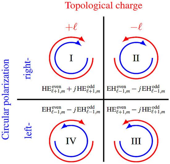
Figure 1.
Four OAM beam representations with the same topological charge [23].
2.2. SC-PCF Structure
To design a PCF supporting OAM mode, the following requirements should be met: (a) the ERID between EH and HE modes in the same OAM mode family should be more than 1 × 10⁻⁴ to avoid coupling between neighboring modes; (b) more OAM modes should be supported by PCF in a larger bandwidth range; (c) the designed PCF should have low CL and NC, large EMFA, high mode purity, and flat dispersion; (d) the fiber structure should match the annular phase of the OAM mode field distribution [25].
Based on the above requirements, this paper proposes an SC-PCF whose cross-sectional diagram is shown in Figure 2. The cladding is designed as a combination of square and circular air holes. By adjusting the size of the air holes appropriately, the ERID between the cladding and the core can be improved without precise doping of the high refractive index material, preventing higher-order mode leakage [16,26].
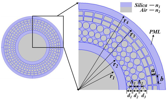
Figure 2.
Cross-sectional diagram of a photonic crystal fiber.
With the development of optical fiber technology, the production of square holes can be realized through sol, gel, casting, and other methods [27]. Jiang et al. [28] proposed a square hole PCF with high birefringence transmission characteristics. Bai et al. [16] proposed a square air hole PCF supporting OAM mode transmission. By using Bessel polygons as air hole cladding, Hassan [29] and Kabir [30] were able to achieve PCFs with low CL and flat dispersion properties. They developed a fused silica-based fiber structure with Bessel polygon air holes to increase the optical properties, based on the fiber structures of the two previous teams. This structure resembles a spider web in cross-section [31]. Vienne et al. [32] used the stack-draw method to draw a hollow-core Bragg fiber with a microstructural cladding. The total length of the fiber is over 150 m and the transmission loss is as low as 1 dB/m. Consequently, it is feasible to fabricate a PCF with square holes.
Figure 2 shows the cross-section of the SC-PCF structure. The gray area describes the air holes and the blue area represents silica. r1 represents the radius of the fiber core, r2 represents the inner diameter of the annular structure, r4 represents the radius of SC-PCF, and the difference between r3 and r4 represents the thickness of the perfect match layer (PML), which can be used to simulate the absorption conditions at the boundary and calculate the transmission characteristics of the PCF. The diameters of the circular air holes on the three layers are d1, d2 and d3, respectively. The length and width of the square air holes on the two outermost layers are a and b, and the spacing of the adjacent air holes is Λ. When designing a PCF, the number and transmission properties of OAM modes are affected by the size and number of air holes in the cladding. After numerical analysis, the optimal parameters were determined as shown in Table 2.

Table 2.
The main parameters of SC-PCF.
3. Simulation Results and Discussion
In this section, the finite element method is adopted to carry out the numerical calculation on the designed SC-PCF, and the transmission characteristics of the OAM mode within the band range from 1400 nm to 1700 nm are analyzed, including OAM mode distribution, effective refractive index (ERI), ERID, dispersion, CL, EMFA, numerical aperture (NA), NC, and mode purity. Because of the risk of “accidental degradation”, OAM mode does not enable radial orders greater than 1, and brings problems to the demultiplexing, reuse, and encoding of OAM mode [14]. Therefore, m = 1 is used in this paper.
3.1. OAM Mode Analysis
Figure 3 and Figure 4 list the mode field distribution and the electric field intensity distribution in Ez direction of OAM modes, respectively. The listed modes can be perfectly confined within the ring. In Figure 3, the mode field distributions of HE and EH modes with the same order are consistent. Therefore, HE and EH modes cannot be effectively distinguished only from the mode field distributions. However, the distribution of electric field intensity between different modes is not consistent. In the Ez direction diagram, the red and blue areas represent electric field intensity. Figure 4 shows that the HE3,1, HE5,1, HE10,1, HE21,1 have 3, 5, 10, 21 pairs of red and blue areas, respectively, and EH mode also has the same rule. At the same time, the electric field intensity of HE mode is closer to the outside of the ring, and that of EH mode is closer to the inside of the ring [16]. Therefore, HE and EH modes can be distinguished by the red–blue pairs of Ez direction and the area of the electric field intensity distribution.
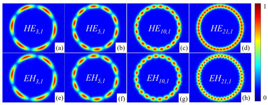
Figure 3.
Mode field distribution diagram: (a) HE3,1, (b) HE5,1, (c) HE10,1, (d) HE21,1, (e) EH3,1, (f) EH5,1, (g) EH10,1, (h) EH21,1.
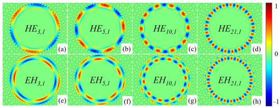
Figure 4.
Electric field intensity distribution diagram: (a) HE3,1, (b) HE5,1, (c) HE10,1, (d) HE21,1, (e) EH3,1, (f) EH5,1, (g) EH10,1, (h) EH21,1.
Referring to Equation (1), OAM mode can be synthesized by the superposition of the odd mode and even mode of HE mode and EH mode. Figure 5 shows the synthesis process and phase diagram of OAM4,1, OAM6,1, OAM11,1, OAM22,1 modes. The phase change of OAM mode is 2πl with the increase in topological charge number, as shown in the figure [15]. As a result, the topological charge number of the OAM mode may be clearly determined from its phase diagram.
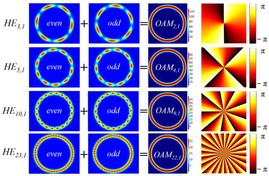
Figure 5.
OAM2,1, OAM4,1, OAM9,1, OAM22,1 mode generation process and corresponding wavefront phase distribution diagram.
According to the composition rule of OAM modes, the SC-PCF proposed in this paper supports the topological charge l = 22 and can carry 86 OAM modes.
3.2. Effective Refractive Index (ERI) and Its Differences (ERID)
ERI (neff) is defined as the average refractive index weighted by light intensity distribution and can be calculated by simulation. Then, the ERID of adjacent vector modes constituting the same order OAM mode can be calculated. Different modes have a different propagation constant β. The relationship between neff and β can be expressed as [33]
where k0 = 2π/λ, represents the wavenumber in the vacuum, and λ is the wavelength.
Figure 6 shows the relationship between wavelength and the ERI in the wavelength range from 1400 nm to 1700 nm. The ERI decreases gradually with increasing wavelength. Meanwhile, the ERI will decrease faster with the increase in mode order, which is caused by the diffusion of the optical field into the cladding.
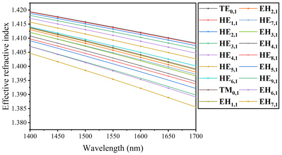
Figure 6.
The relation between ERI and wavelength in different vector modes.
Figure 7 shows the ERID between modes supported by SC-PCF. The figure shows that the ERID increases gradually as the wavelength increases, and that the greater the order, the lower the ERID. Furthermore, all ERIDs are greater than 1 × 10⁻⁴. At the wavelength of 1550 nm, the ERID between HE3,1 and EH1,1 is as high as 5.88 × 10⁻³, which is much larger than the recently published reference [21]. The large ERID indicates that the fiber has great mode separation characteristics, which is of great research value in multi-channel fiber communication systems. To avoid coupling between adjacent modes, the ERID should be greater than 1 × 10⁻⁴. The ERID can be expressed by the following equation [34]:
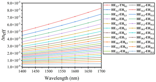
Figure 7.
The relation between ERID and wavelength in different vector modes.
3.3. Dispersion Properties
Dispersion is an important transmission characteristic of the optical fiber. The dispersion will cause light pulse broadening and signal transmission distortion; thus, the optical communication transmission bandwidth is limited. The lower the dispersion, the greater the information capacity carried. Dispersion in the optical fiber includes material dispersion and waveguide dispersion, but material dispersion is usually not considered in long-distance communication. The waveguide dispersion of SC-PCF was calculated by the following equation [35]:
where c = 2.9979 × 10⁸ m/s represents the speed of light in vacuum, and Re (neff) is the real part of the ERI.
The dispersion of SC-PCF is shown in Figure 8. In the range from 1400 nm to 1700 nm, the dispersion of the higher-order mode increases with the increase in wavelength, whereas that of lower-order modes increases more flatly with the increase in wavelength, which is connected to the change in ERI with wavelength. The EH mode has a higher dispersion than the HE mode. In addition, the dispersion increases as the mode order increases, so the higher-order mode will cause pulse broadening, leading to the instability of the mode transmission. The minimum dispersion changes by 0.956 ps/nm/km, indicating that the dispersion changes of various modes are relatively stable. The dispersion changes of HE1,1, HE2,1, HE3,1, and HE4,1 modes are 0.973 ps/nm/km, 1.024 ps/nm/km, 1.108 ps/nm/km, and 1.228 ps/nm/km, which are far lower than the minimum dispersion value in the recently proposed reference [18,30,35]. At the wavelength of 1550 nm, the lowest dispersion is only 4.939 ps/nm/km, and the overall dispersion is less than 71.6 ps/nm/km. The dispersion is relatively flat, which is conducive to the transmission of OAM mode in the fiber.
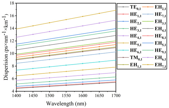
Figure 8.
The relation between dispersion and wavelength in different vector modes.
3.4. Confinement Loss (CL)
CL, which means that the light field spills out from the fiber core to the cladding during transmission, is an important transmission parameter in SC-PCF, resulting in partial energy loss. This leads to a reduction in beam quality and shortens the transmission distance ultimately. By adjusting the number and diameter of air holes in the cladding, CL can be reduced effectively. CL can be calculated by the imaginary part of the ERI, which is expressed in the following form [36]:
where Im (neff) represents the imaginary part of the ERI.
Figure 9 shows the CL distribution of different modes in the range of 1550 nm. It can be seen that the fluctuation of each mode is obvious without uniform regularity, but the overall loss is confined to the order of 10−8 dB/m–10−11 dB/m, showing a relatively low CL. This is caused mainly by the high refractive index ring and the layer-by-layer amplification of the air hole structure. At the wavelength of 1550 nm, the CL of EH16,1 mode is the lowest, which is 1.55 × 10⁻¹¹ dB/m, as low as the lower-order mode of a similar structure [11,12,14]; the CL of EH3,1 mode is 3.13 × 10⁻¹⁰ dB/m, lower than the existing PCFs [35].
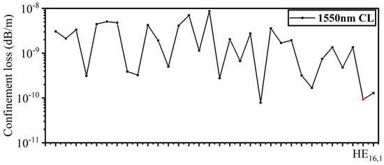
Figure 9.
The distribution of CL for different vector modes at 1550 nm.
3.5. Effective Mode Field Area (EMFA)
The EMFA is used to represent the energy concentration of the mode. The smaller the EMFA, the more concentrated the energy. The quality of the mode field directly affects the NA and NC of the optical fiber, so the EMFA is an important research parameter in SC-PCF. Aeff can be used to express the EMFA of the OAM mode, and the formula can be used to compute it [36]:
where E (x,y) represents the electric field distribution in the cross-section of the SC-PCF.
Figure 10 shows the relationship between Aeff and wavelength. It can be seen from the figure that Aeff tends to rise with the increase in wavelength. Through analysis of dispersion and CL, it indicates that the larger the wavelength, the weaker the limiting ability of the light field, and the energy of the fiber core leaks into the cladding gradually, leading to energy divergence, and Aeff increases gradually. It can be seen from Figure 10 that the relationship between Aeff and wavelength changes linearly. In the range from 1400 nm to 1700 nm, the overall distribution of Aeff is from 60 μm2 to 110 μm2. At the wavelength of 1550 nm, the TM0,1 mode has the largest Aeff of 107.57 μm2, higher than the current PCFs [31,35,37].
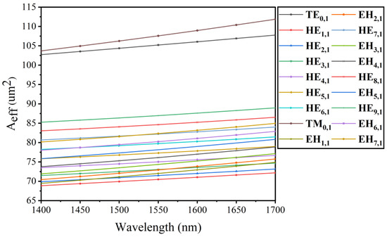
Figure 10.
The relation between EMFA and wavelength in different vector modes.
3.6. Numerical Aperture (NA)
NA represents the total amount of light energy in the fiber, which determines how much light energy the fiber collects, and this has important applications in the optical field. A higher NA is needed to improve the optical energy stored in the fiber core, when designing a fiber, which can be expressed as the ratio of Aeff to wavelength [31].
Referring to Equation (7), NA can be increased by increasing the wavelength and decreasing Aeff. Figure 11 shows the changing relationship between wavelength and NA. The NA at 1550 nm is lower than 0.11, and the low NA is conducive to its application in the field of coherent layer analysis and imaging [38].
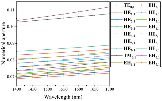
Figure 11.
The relation between NA and wavelength in different vector modes.
3.7. Nonlinearity Coefficient (NC)
Nonlinearity is one of the most important optical characteristics in SC-PCF. Nonlinearity is usually represented by NC. The smaller NC, the weaker the nonlinearity, and the better the transmission efficiency of the information in the optical fiber. NC is represented by γ [36]:
where n2 = 2.3 × 10⁻²⁰ m2/W indicates silica’s nonlinear refractive index. NC is proportional to n2 and inversely proportional to Aeff, so that the NC decreases with the increase in EMFA.
Figure 12 shows the relationship between wavelength and NC. In the range from 1400 nm to 1700 nm, the overall NC is less than 1.5 W−1·km−1, showing extremely low NC, especially at 1700 nm; the lowest NC in TM0,1 mode is 0.789 W−1·km−1. Optical communication mainly works in the C-band around 1550 nm, where the minimum NC of TM0,1 mode is 0.867 W−1·km−1, which is 0.1 W−1·km−1 to 2 W−1·km−1 lower than the PCF structures proposed in recent years [18,21,35]. It is more conducive to the stable transmission of OAM mode in the optical fiber and has broad application prospects. For example, in optical fiber communication, suitable nonlinearity can be obtained by designing photonic crystal fibers with special structures, which can be used to make optical fiber communication devices, such as Raman fiber amplifiers, optical parametric amplifiers, etc. [39,40,41]; in optical soliton research, optical fibers can be used with nonlinear effects in the design of pulse compression or all-optical switches [42,43].
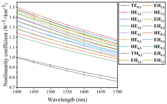
Figure 12.
The relation between NC and wavelength in different vector modes.
3.8. Mode Purity
Mode purity is also an important parameter to be considered in PCF design. High mode purity can ensure stable transmission and improve the transmission efficiency of OAM mode in the optical fiber. Mode purity can be expressed by the weight of mode intensity on the cross-section of the fiber [34].
where Ir represents the average mode intensity in the annular region of the SC-PCF. Ic represents the average mode intensity across the cross-section of the SC-PCF.
At 1550 nm, Figure 13 shows the mode purity for all modes supported by the SC-PCF. The mode purity of lower-order modes is higher than that of higher-order modes, as shown in the figure, and the values of mode purity for all modes are greater than 96%, with the mode purity of TE0,1 mode reaching 97.9%. As a result, the optical fiber structure presented in this study can ensure the stable transmission of OAM mode and improve the information transmission efficiency at C-band.
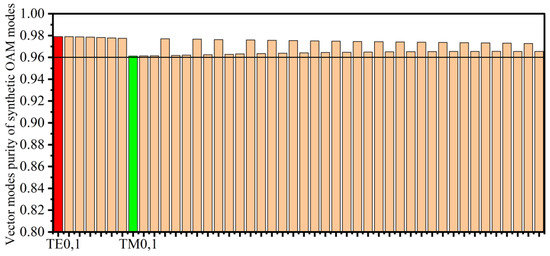
Figure 13.
Mode purity of different vector modes at 1550 nm.
3.9. Comparison with Existing Typical PCFs
The SC-PCF proposed in this paper has been numerically calculated and its transmission characteristics have been analyzed. Table 3 lists the comparison of transmission characteristics between the SC-PCF proposed in this paper and the existing PCF without high refractive index material doping, including the number of OAM modes, dispersion at 1550 nm, CL, EMFA, NC, and mode purity. The SC-PCF supports 86 OAM modes, which is the maximum compared to the existing PCFs. The dispersion at 1550 nm of SC-PCF is from 4.939 ps/nm/km to 71.6 ps/nm/km, and CL is from 10−11 dB/m to 10−8 dB/m. It indicates that these two parameters are at extremely low levels. The large EMFA minimizes the NC of SC-PCF. At the same time, the mode purity of all modes is higher than 96%, which is at the highest level overall compared to the existing PCFs in the table. The comparison shows that the SC-PCF has excellent transmission characteristics. More modes can ensure that the optical fiber carries more information in the multiplexing system. Low dispersion, CL, NC, and high mode purity in the optical fiber are beneficial to improved OAM mode stability and long-distance transmission.

Table 3.
OAM fibers based on PCF structures.
Table 3.
OAM fibers based on PCF structures.
| Year | Number of OAM Modes | 1550 nm Dispersion (ps/nm/km) | Confinement Loss (dB/m) | Effective Mode Field Area (μm2) | Nonlinear Coefficient (w−1·km−1) | Mode Purity (%) | Bandwidth (nm) | Reference |
|---|---|---|---|---|---|---|---|---|
| 2016 | 26 | flat | <10−9 | - | 356.2 (HE3,1) | - | 1100–2000 | [44] |
| 2018 | 46 | >50 | <10−9 | 54.25 (HE3,1) | <2.58 | - | 1200–2000 | [16] |
| 2018 | 54 | >53.29 | <10−9 | >48 | 1.41–2.1 | - | 1500–1600 | [17] |
| 2020 | 26 | <25 | <10−8 | >35 | 2–3 | - | 800–1800 | [31] |
| 2020 | 38 | >4.75 | >10−10 | - | >1.04 | >85 | 800–2000 | [30] |
| 2020 | 56 | >36.91 | 10−8 | >60 | <4 | <94 | 600–2500 | [45] |
| 2020 | 50 | >46.96 | <10−9 | >80 | 0.6–1.5 | - | 1150–2000 | [18] |
| 2020 | 56 | - | >10−8 | - | - | >80 | 1400–1700 | [46] |
| 2021 | 30 | >3.59 | <10−8 | 30–50 | <4.144 | >90 | 1350–1800 | [37] |
| 2021 | 44 | >50 | >10−10 | 40–65 | <3.36 | - | 1150–1800 | [47] |
| 2021 | 86 | >4.939 | <10−9 | 60–110 | 0.867–1.5 | >96 | 1400–1700 | this paper |
4. Conclusions
In this paper, a novel PCF structure consisting of square and circular air holes is proposed. The SC-PCF is simulated using software based on the finite element method, and the transmission characteristics of the structure in the S + C + L band are analyzed. The structure enables 86 OAM modes in the wavelength range of 1400 nm to 1700 nm, according to the research, and the ERID between the modes is as high as 5.88 × 10⁻³, which avoids the coupling between adjacent vector modes into LP mode effectively. The minimum dispersion of the modes is 4.939 ps/nm/km, and the minimum change in dispersion is 0.956 ps/nm/km. The CL of all modes is less than 10−9 dB/m. At the same time, the EMFA ranges from 60 um2 to 110 um2, and the large EMFA causes the fiber to have extremely low NC (0.867 W−1·km−1). The mode purity of all modes is greater than 96% at the wavelength of 1550 nm. According to these specifications, the SC-PCF has a flat dispersion, low CL, and high mode purity. Through the numerical analysis of the SC-PCF proposed, it supports a large number of OAM modes for stable transmission, has the characteristics of large capacity and low loss, and has a broad application prospect in multiplexing communication systems.
Author Contributions
Conceptualization, Y.Y. and Y.L.; data curation, Q.H. and L.X.; formal analysis, Y.Y.; funding acquisition, Q.H. and J.D.; project administration, J.D.; supervision, Y.L., Y.W. and Z.L.; writing—original draft, Y.Y.; writing—review and editing, Y.Y. and Y.L. All authors have read and agreed to the published version of the manuscript.
Funding
This research was funded by the National Natural Science Foundation of China (61905062, 61927815 and 62070506), China Postdoctoral Science Foundation (2020M670613), and Hebei Postdoctoral Scholarship Project (B2020003026). We acknowledge the support of the Key Laboratory of all optical networks and advanced communications networks of the Ministry of Education (Beijing Jiaotong University) (AON2019005).
Institutional Review Board Statement
Not applicable.
Informed Consent Statement
Not applicable.
Data Availability Statement
Not applicable.
Conflicts of Interest
The authors declare no conflict of interest.
References
- Ellis, A.D.; Jian, Z.; Cotter, D. Approaching the Non-Linear Shannon Limit. J. Lightw. Technol. 2010, 28, 423–433. [Google Scholar] [CrossRef]
- Ellis, A.; Doran, N. Are few-mode fibres a practical solution to the capacity crunch? In Proceedings of the 2013 15th International Conference on Transparent Optical Networks (ICTON), Cartagena, Spain, 23–27 June 2013. [Google Scholar]
- Huang, S.; Lin, W.; Chen, M. Cross-talk analysis of time-division multiplexing of polarization-insensitive fiber-optic Michelson interferometric sensors with a 3 × 3 directional coupler. Appl. Opt. 1997, 36, 921–933. [Google Scholar] [CrossRef] [PubMed]
- Slaveski, F.; Sluss, J., Jr.; Atiquzzaman, M.; Nguyen, H.; Ngo, D. Optical fiber wavelength division multiplexing. IEEE Aerosp. Electron. Syst. Mag. 2003, 18, 3–8. [Google Scholar] [CrossRef]
- Yi, A.; Yan, L.; Luo, B.; Pan, W.; Ye, J. All-Optical Signal Regeneration in Polarization-Division-Multiplexing Systems. IEEE Photonics J. 2011, 3, 703–712. [Google Scholar] [CrossRef]
- Mizuno, T.; Takara, H.; Shibahara, K.; Sano, A.; Miyamoto, Y. Dense Space Division Multiplexed Transmission over Multicore and Multimode Fiber for Long-haul Transport Systems. J. Lightw. Technol. 2016, 34, 1484–1493. [Google Scholar] [CrossRef]
- Richardson, D.J.; Fini, J.M.; Nelson, L.E. Space-division multiplexing in optical fibres. Nat. Photonics 2013, 7, 354–362. [Google Scholar] [CrossRef]
- Yan, Y.; Xie, G.; Lavery, M.P.J.; Huang, H.; Ahmed, N.; Bao, C.; Ren, Y.; Cao, Y.; Li, L.; Zhao, Z.; et al. High-capacity millimetre-wave communications with orbital angular momentum multiplexing. Nat. Commun. 2014, 5, 1–9. [Google Scholar] [CrossRef]
- Huang, H.; Milione, G.; Lavery, M.P.J.; Xie, G.; Ren, Y.; Cao, Y.; Ahmed, N.; Nguyen, T.; Nolan, D.A.; Li, M.; et al. Mode division multiplexing using an orbital angular momentum mode sorter and MIMO-DSP over a graded-index few-mode optical fibre. Sci. Rep. 2015, 5, 1–7. [Google Scholar] [CrossRef]
- Willner, A.E.; Huang, H.; Yan, Y.; Ren, Y.; Ahmed, N.; Xie, G.; Bao, C.; Li, L.; Cao, Y.; Zhao, Z.; et al. Optical communications using orbital angular momentum beams. Adv. Opt. Photonics 2015, 7, 66–106. [Google Scholar] [CrossRef]
- Guo, Z.; Gong, C.; Liu, H.; Li, J.; Wang, Z.; Yang, Y.; Gong, Y. Research advances of orbital angular momentum based optical communication technology. Opto-Electron. Eng. 2020, 47, 190593. [Google Scholar]
- Wang, W.; Hou, L. Present Situation and Future Development in Photonic Crystal Fibers. Laser Optoelectron. Prog. 2008, 45, 43–58. [Google Scholar] [CrossRef]
- Yue, Y.; Zhang, L.; Yan, Y.; Ahmed, N.; Yang, J.; Huang, H.; Ren, Y.; Dolinar, S.; Tur, M.; Willner, A.E. Octave-spanning supercontinuum generation of vortices in an As2S3 ring photonic crystal fiber. Opt. Lett. 2012, 37, 1889–1891. [Google Scholar] [CrossRef]
- Zhang, H.; Zhang, X.; Li, H.; Deng, Y.; Xi, L.; Tang, X.; Zhang, W. The Orbital Angular Momentum Modes Supporting Fibers Based on the Photonic Crystal Fiber Structure. Crystals 2017, 7, 286. [Google Scholar] [CrossRef]
- Tian, W.; Zhang, H.; Zhang, X.; Xi, L.; Zhang, W.; Tang, X. A circular photonic crystal fiber supporting 26 OAM modes. Opt. Fiber Technol. 2016, 30, 184–189. [Google Scholar] [CrossRef]
- Bai, X.; Chen, H.; Yang, H. Design of a circular photonic crystal fiber with square air-holes for orbital angular momentum modes transmission. Opt. Int. J. Light Electron. Opt. 2018, 158, 1266–1274. [Google Scholar] [CrossRef]
- Yang, H. Design and Performance Analysis of a Novel Photonic Crystal Fiber for OAM Mode Transmission; Nanjing University of Posts and Telecommunications: Nanjin, China, 2018; pp. 25–30. [Google Scholar]
- Ke, X.; Wang, S. Design of Photonic Crystal Fiber Capable of Carrying Multiple Orbital Angular Momentum Modes Transmission. Opt. Photonics J. 2020, 10, 49–63. [Google Scholar] [CrossRef][Green Version]
- Hong, S.; Lee, Y.S.; Choi, H.; Quan, C.; Li, Y.; Kim, S.; Oh, K. Hollow silica photonic crystal fiber guiding 101 orbital angular momentum modes without phase distortion in C + L band. J. Lightw. Technol. 2020, 38, 1010–1018. [Google Scholar] [CrossRef]
- Ma, Q.; Luo, A.P.; Hong, W. Numerical Study of Photonic Crystal Fiber Supporting 180 Orbital Angular Momentum Modes with High Mode Quality and Flat Dispersion. J. Lightw. Technol. 2021, 39, 2971–2979. [Google Scholar] [CrossRef]
- Zhao, L.; Zhao, H.; Xu, Z.; Liang, R. A Design of Novel Photonic Crystal Fiber with Low and Flattened Dispersion for Supporting 84 Orbital Angular Momentum Modes. Commun. Theor. Phys. 2021, 73, 085501. [Google Scholar] [CrossRef]
- Ramachandran, S.; Kristensen, P. Optical Vortices in Fiber. Nanophotonics 2013, 2, 455–474. [Google Scholar] [CrossRef]
- Brunet, C.; Vaity, P.; Messaddeq, Y.; LaRochelle, S.; Rusch, L.A. Design, fabrication and validation of an OAM fiber supporting 36 states. Opt. Express 2014, 22, 26117–26127. [Google Scholar] [CrossRef] [PubMed]
- Wei, W.; Zhang, L.; Zhang, Z.; Tang, L.; Ding, L.; Li, Y. Design of Three Vortex Photonic Crystal Fibers. Acta Opt. Sin. 2019, 39, 0906006. [Google Scholar] [CrossRef]
- Zhang, H.; Zhang, X.; Li, H.; Deng, Y.; Zhang, X.; Xi, L.; Tang, X.; Zhang, W. A design strategy of the circular photonic crystal fiber supporting good quality orbital angular momentum mode transmission. Opt. Commun. 2017, 397, 59–66. [Google Scholar] [CrossRef]
- Zhang, X.; Yuan, M.; Chang, M.; Lu, X.; Chen, N.; Nie, F.; He, M.; Qi, N.; Zhuang, S. Characteristics in square air hole structure photonic crystal fiber. Opto-Electron. Eng. 2018, 45, 170633. [Google Scholar]
- Yajima, T.; Yamamoto, J.; Ishii, F.; Hirooka, T.; Yoshida, M.; Nakazawa, M. Low-loss photonic crystal fiber fabricated by a slurry casting method. Opt. Express 2013, 21, 30500–30506. [Google Scholar] [CrossRef]
- Jiang, G.; Fu, Y.; Huang, Y. High birefringence rectangular-hole photonic crystal fiber. Opt. Fiber Technol. 2015, 26, 163–171. [Google Scholar] [CrossRef]
- Hassan, M.M.; Kabir, M.A.; Hossain, M.N.; Biswas, B.; Paul, B.K.; Ahmed, K. Photonic crystal fiber for robust orbital angular momentum transmission: Design and investigation. Opt. Quantum Electron. 2020, 52, 1–14. [Google Scholar] [CrossRef]
- Kabir, M.A.; Hassan, M.M.; Hossain, M.N.; Paul, B.K.; Ahmed, K. Design and performance evaluation of photonic crystal fibers of supporting orbital angular momentum states in optical transmission. Opt. Commun. 2020, 467, 125731. [Google Scholar] [CrossRef]
- Kabir, M.A.; Hassan, M.M.; Ahmed, K.; Rajan, M.S.M.; Aly, A.H.; Hossain, M.N.; Paul, B.K. Novel spider web photonic crystal fiber for robust mode transmission applications with supporting orbital angular momentum transmission property. Opt. Quantum Electron. 2020, 52, 1–17. [Google Scholar] [CrossRef]
- Vienne, G.; Xu, Y.; Jakobsen, C.; Deyerl, H.; Jensen, J.B.; Srensen, T.; Hansen, T.P.; Huang, Y.; Terrel, M.; Lee, R.K.; et al. Ultra-large bandwidth hollow-core guiding in all-silica Bragg fibers with nano-supports. Opt. Express 2004, 12, 3500–3508. [Google Scholar] [CrossRef]
- Al-Zahrani, F.A.; Kabir, M. Ring-Core Photonic Crystal Fiber of Terahertz Orbital Angular Momentum Modes with Excellence Guiding Properties in Optical Fiber Communication. Photonics 2021, 8, 122. [Google Scholar] [CrossRef]
- Kabir, M.A.; Ahmed, K.; Hassan, M.M.; Hossain, M.M.; Paul, B.K. Design a photonic crystal fiber of guiding terahertz orbital angular momentum beams in optical communication. Opt. Commun. 2020, 475, 126192. [Google Scholar] [CrossRef]
- Zhang, L.; Meng, Y. Design and analysis of a photonic crystal fiber supporting stable transmission of 30 OAM modes. Opt. Fiber Technol. 2021, 61, 102423. [Google Scholar] [CrossRef]
- Hassan, M.M.; Kabir, M.A.; Hossain, M.N.; Nguyen, T.K.; Paul, B.K.; Ahmed, K.; Dhasarathan, V. Numerical analysis of circular core shaped photonic crystal fiber for orbital angular momentum with efficient transmission. Appl. Phys. B. 2020, 126, 1–8. [Google Scholar] [CrossRef]
- He, T.; Wu, B. Low confinement loss photonic crystal fibre capable of supporting 54 orbital angular momentum modes. J. Mod. Opt. 2020, 67, 1–7. [Google Scholar] [CrossRef]
- Liu, G.; Zhi, Z.; Wang, R.K. Digital focusing of OCT images based on scalar diffraction theory and information entropy. Biomed. Opt. Express 2012, 3, 2774–2783. [Google Scholar] [CrossRef] [PubMed]
- Zhang, H.; Tao, R.; Zhou, P.; Wang, X.; Xu, X. 1.5-kW Yb-Raman combined nonlinear fiber amplifier at 1120 nm. IEEE Photonics Technol. Lett. 2014, 27, 628–630. [Google Scholar] [CrossRef]
- Marhic, M.E. Fiber Optical Parametric Amplifiers, Oscillators and Related Devices; Cambridge University Press: Cambridge, MA, USA, 2008. [Google Scholar]
- Headley, C.; Agrawal, G. Raman Amplification in Fiber Optical Communication Systems; Academic Press: Cambridge, MA, USA, 2005. [Google Scholar]
- Bian, J.R.; Chan, A.K. Computations of the diffraction effect and the nonlinear effect on spatial solitons in nonlinear planar waveguides. Microw. Opt. Technol. Lett. 1991, 4, 184–191. [Google Scholar] [CrossRef]
- Alfassi, B.; Rotschild, C.; Manela, O.; Segev, M.; Christodoulides, D.N. Boundary force effects exerted on solitons in highly nonlocal nonlinear media. Opt. Lett. 2007, 32, 154–156. [Google Scholar] [CrossRef]
- Zhang, H.; Huang, Y.; Luo, A.; Cui, H.; Luo, Z.; Xu, W. Photonic crystal fiber for supporting 26 orbital angular momentum modes. Opt. Express 2016, 24, 17285–17291. [Google Scholar]
- Israk, M.F.; Razzak, M.A.; Ahmed, K.; Hassan, M.M.; Kabir, M.A.; Hossain, M.N.; Paul, B.K.; Dhasarathan, V. Ring-based coil structure photonic crystal fiber for transmission of Orbital Angular Momentum with large bandwidth: Outline, investigation and analysis. Opt. Commun. 2020, 473, 126003. [Google Scholar] [CrossRef]
- Wang, W.; Wang, N.; Li, K.; Geng, Z.; Jia, H. A novel dual guided modes regions photonic crystal fiber with low crosstalk supporting 56 OAM modes and 4 LP modes. Opt. Fiber Technol. 2020, 57, 102213. [Google Scholar] [CrossRef]
- Wang, W.; Wang, N.; Jia, H. Research on the Dispersion Characteristics of Silica-based Ring-core Photonic Crystal Fiber Used to Transmit Orbital Angular Momentum Modes. Optik 2021, 241, 166935. [Google Scholar] [CrossRef]
Publisher’s Note: MDPI stays neutral with regard to jurisdictional claims in published maps and institutional affiliations. |
© 2022 by the authors. Licensee MDPI, Basel, Switzerland. This article is an open access article distributed under the terms and conditions of the Creative Commons Attribution (CC BY) license (https://creativecommons.org/licenses/by/4.0/).


