1. Introduction
Light field display is a three-dimensional (3D) display technology developed from integral imaging theory. It usually uses a glass microlens array (MLA) to record and reconstruct 3D scenes [
1]. In contrast to traditional 3D display solutions, light field display exhibits an actual 3D effect without extra auxiliary head-instruments, real stereoscopic vision-image. It has continuous viewpoints and full-parallax, and a functional, simple optical architecture [
2,
3]. Furthermore, it is advantageous for effectively solving the accommodation-convergence conflict, namely the most common issue of the conventional 3D display.
Enhancing the performance of light field displays has become a hot research spot worldwide in recent years [
4]. The main aspects of improvements are spatial resolution and field of view (FOV), respectively [
5]. Javidi has proposed the moving microlens array technology (MLAT) to reduce MLA interval [
6]. In this regard, the lateral resolution was enhanced. Therefore, the display performance was also improved. According to this idea, two other similar methods have been given to enhance the performance of the light field display, such as using a liquid crystal (LC) MLA [
7] and rotating a prism [
8]. Stern has introduced a synthetic aperture approach to enhance FOV, namely computational synthetic aperture integral imaging (COMPSAII) [
9]. Baasantseren used two masks with specific patterns to acquire a larger FOV [
10]. Furthermore, Wang designed a method with a spatial light modulator (SLM) to block unnecessary rays, leading elemental image array (EIA) to the corresponding MLAs [
11]. Okaichi adopted a curved MLA to realize a light field display with a wider FOV, replacing the regular glass type MLA [
12]. However, these methods usually require bulky optical instruments with relatively complex operations to guarantee performance. Significantly, the glass type MLA or corresponding functions compromise the spatial resolution and FOV for light field display. Hence, the conventional glass type MLA becomes the bottleneck of light field display for performance improvement.
Applying several novel optical elements in light field display has become very popular in the past decades, especially in LC devices. Lei took the lead in utilizing LC-MLA in light field imaging [
13]. With the LC-MLA’s electrically tunable focal length feature, the imaging system’s depth of field (DOF) has a relatively greater extension compared to the regular glass type MLA. Correspondingly, Algorri has realized a tunable FOV imaging capture system, demonstrated via an electrically tunable LC-MLA [
14]. In this regard, the FOV has a specified adjustment range. The LC-MLA and OLED display have presented 2D/3D display effects as needed [
15]. Xin changed the structure of the regular LC-MLA and added a twisted nematic LC layer in acquiring 2D imaging, light field imaging, and polarization imaging of the scene [
16]. A Pancharatnam-Berry (PB) MLA with LC alignment via a rapid nano-imprinting method has been fabricated [
17]. This kind of MLA has an excellent imaging capability. A new virtual reality system via LED has been demonstrated [
18].
However, the existing architecture of the light field display with LC-MLA still suffers from the narrow FOV and not high resolution [
19,
20]. On the other hand, the polarization feature of the LC-MLA induces low-quality resolution due to halving the light amount. Eliminating the ordinary wave (o-wave) of LC-MLA imaging results formed by the natural incident ray is the key driver of the resolution performance improvement for light field display based on LC-MLA.
To address the issues of low resolution and narrow FOV, we demonstrated a light field display with LC-MLA via polymer-dispersed liquid crystal (PDLC) film. A prototype system has been presented. LC-MLA generated the high-resolution 3D images with the depolarization algorithm. The PDLC film modulated the incident ray to acquire full-parallax images with a wide FOV. The introduction of the LC-MLA and PDLC film can effectively enhance the performance of light field displays. This study is organized as follows. First, the light field display architecture with LC-MLA and PDLC film is introduced. Subsequently, the fabrication and characterization of the core elements are given. Then, the proposed system is verified with several light field display experiments. Finally, the system’s reliability is discussed, and the work is summarized.
2. Methods and System Design
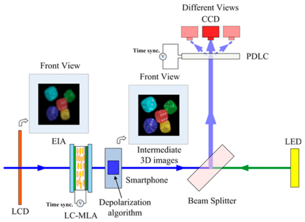
The proposed light field display system mainly consists of LC-MLA, PDLC film, beam splitter, and light-emitting diode (LED).
Figure 1 illustrates the proof-of-principle system, where an optical architecture is given. An LCD panel was employed to present EIAs. With the smartphone, the depolarization algorithm was used to eliminate the polarization issue of the LC-MLA. After computing, the high-resolution intermediate 3D images are reconstructed on the smartphone’s display panel in video mode. The PDLC film by the externally applied voltage is a critical optical element for producing 3D images clearly. The adopted PDLC film primarily determines the scattering characteristic because of the wide FOV. A LED was utilized to provide sufficient intensity of light amount via a beam splitter to construct clear views.
2.1. Light Field Acquisition
An essential step in achieving light field display is to obtain EIAs, namely the light field transverse section information of the object in a scene. The following part presents the procedure of the light field acquisition. According to the trajectory of the ray, an incident ray has spatial coordinates and angular coordinates , which are used to parameterize the ray. With the use of this five-dimensional (5D) function, the light field of the incident ray is described. For brevity calculation, the plenoptic function becomes .
For a plane
in the light field, it has [
21],
where the plane
means an image plane of LC-MLA, the plane
refers to a plane at a distance d from the main lens, f is the focal length of the LC-MLA. The two-dimensional image on the plane
is calculated by the following formula [
21],
Using Equation (2), any planes in the light field could be calculated. Therefore, with the biplanes model, the light field information of a scene is recorded by an LC-MLA. According to the principle of optical path reversibility, the light field display results can be obtained.
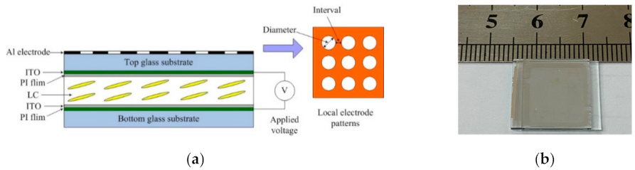
2.2. LC-MLA
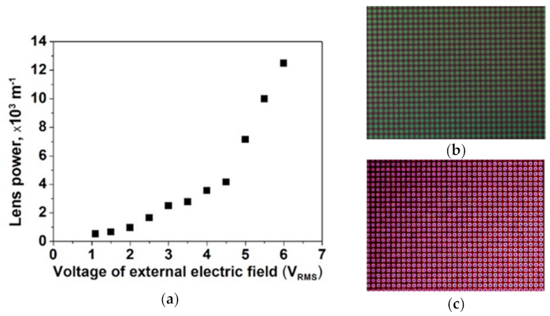
LC-MLA has an electronically tunable focal length feature compared to the glass type MLA. When applied in the light field acquisition or display, its adaptive electronically controllable characteristic improves performance on DOF [
13] and FOV [
14]. However, owing to the natural feature of LC materials, the LC-MLA has a polarization issue. To remove the effects of polarization, an image processing method, so-called “PFI” (polarizer-free imaging), has been proposed [
22]. Generally, there are two states of LC-MLA, non-lens state and lens state, in generating two-dimensional (2D) optical imaging. This solution is introduced to realize the high-resolution intermediate 3D images using LC-MLA.
For the non-lens state, the ray from EIA on the LCD panel combined with o-wave and extraordinary wave (e-wave) through the no activated LC-MLA without applied voltage. At this time, the presented intermediate 3D images based on integral imaging theory overlapped both o-wave and e-wave, namely = . In the natural ray situation, = . As such, o-wave and e-wave have the half energy of the incident ray. On the other hand, for lens state, the ray from EIA on LCD panel was also carried with o-wave and e-wave, Ilens = .
Nevertheless, when the incident ray was through the activated LC-MLA with the externally applied voltage, there is gradient refractive index distribution in every cell of the LC-MLA. Only e-wave is tunable by the activated LC-MLA, and o-wave has no affection for the activated LC-MLA. Under the externally applied voltage, the LC director in the LC layer has begun to rotate. At the center of the circular electrode, the refractive index of the LC director sees ne. At the edge areas, the refractive index of the LC director sees no. The transition areas of the circular electrode, the refractive index of LC director sees
, where
means the angle between the incident ray and LC director. Combining the two states of LC-MLA, the high-resolution intermediate 3D image is presented. For quantitative description, the following formula has been given,
On the smartphone, high-resolution intermediate 3D images were produced with the state of lens and the non-lens state . Therefore, the resolution is improved. Then, different intermediate 3D images under different externally applied voltages were presented on the smartphone’s display panel in video mode. This major improvement by using a depolarization algorithm exceeds the original method with just an LC-MLA to a certain extend.
2.3. PDLC Film
After computing on the smartphone, the reconstructed intermediate 3D images appeared on the display panels of the smartphone in video mode. Generally, PDLC film was applied as an optical switching device using its scattering feature in several optical imaging applications [
23,
24,
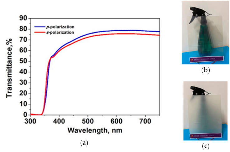
25]. The performance of the proposed light field display benefits from this scattering feature to widen the FOV. Therefore, using PDLC film in the proposed light field display system becomes another major improvement over the conventional light field display, especially with LC-MLA. PDLC film has two operation modes, transparent state, and scattering state. In the PDLC system, nematic LCs were evenly dispersed in the UV photosensitive polymer matrix with micron-sized droplets. Without applied voltage, the optical axis of each tiny droplet was in a preferred orientation.
When voltage is applied, the optical axis of all particles turns into a disordered orientation [
26]. LC is an electro-optical material with strong optical and dielectric anisotropy. Its effective refractive index does not match the refractive index of the adopted polymer matrix. Thus, the incident light strongly scatters into an opaque or translucent milky state [
27]. Under this condition, it is very appropriate to expand the FOV of the proposed light field display.
Nevertheless, when the external electric field was applied, the optical axis direction of LC molecules aligned along the electric field direction, from positive to negative direction. The ordinary refractive index of LC particles matches the refractive index of the matrix to a certain extent. The light passed through the matrix in a transparent state. As such, the transmittance of the PDLC is modulated by the externally applied voltage. The transmittance formula is [
28],
where
,
TA is the maximum transmittance,
χ denotes the density of LC droplets,
σ means the average scattering cross-section,
d refers to the thickness of polymer film, and
Eext is the externally applied voltage.
With the use of the LC-MLA, 3D images were reproduced. However, through the PDLC film, the modulated light field information allowed to present a larger FOV. Moreover, the scattering feature of the PDLC film lost partial detailed information. A high transmittance state could ensure detailed information with the external tunable applied voltage. In contrast, a low transmittance state could increase the intensity of the scattered field. The final light field image benefits from combining the two above states. Therefore, when the applied voltage was not added on, the PDLC film was at a low transmittance state, and the incident rays fell on CCD. While the externally applied voltage increased, the transmittance state changed to the high transmittance state. Therefore, the image on CCD was
I0 at 0 V
rms. With the applied voltage
V1, the image on CCD became
I1. Using the applied voltage
V2, the image on CCD turned out
I2. Then, the last image on CCD at the applied voltage
Vn was
In. The external applied voltage changes from 0 V
rms to 10 V
rms at a step size of 1 V
rms. Thus, the final light field image was,
Several images containing modulated light field information were fused using the persistence effect of human eyes. The loading of the externally applied voltage strategy of PDLC film is time synchronization with the LC-MLA. Consequently, the high-resolution 3D images with a larger FOV satisfied the viewer’s requirement for light field display.
2.4. Light Field Display
To realize the high-resolution light field display with a wide FOV, we used the LC-MLA, PDLC film, beam splitter, smartphone, and LED as the main elements for constituting the light field display system. The designed system provides two major improvements over the conventional light field display system, especially LC-MLA. First, the depolarization algorithm was applied to remove the polarization issue of the LC materials. With the use of this solution, the display panels of the smartphone in video mode presented high-resolution intermediate 3D images over the conventional method. Second, a PDLC film has a strongly scattering feature due to PDLC morphology and interfacial force between polymer and LC. Then, the strategy of applying PDLC film in the system was modulated to widen the FOV of the proposed system.
Moreover, the LED enhanced the intensity of the incident light amount to compensate for energy attenuation caused by multiple times propagating through the primary optical element in the proposed system. As such, the final light field display results were compromised either by using the depolarization algorithm to achieve high-resolution intermediate 3D images or by using the modulated PDLC film to widen the FOV of the system.
With geometric optics, FOV of the proposed system under the condition of PDLC film and LED is deduced as [
29],
where
P means the aperture of the LC-MLA. Then,
g refers to the distance between the LC-MLA and the LCD panel. Multi-times electrically tunable equivalently shorten the distance g because of the focal length changing [
14]. Thus, the FOV is also expanded.
4. Results and Discussions
The experimental setup of the proposed light field display mainly consists of LC-MLA, smartphone, PDLC film, beam splitter, and LED, as shown in
Figure 1. A 17-inch Philips 17S4SB monitor was used as a display panel for exhibiting the EIAs, which could operate at 5 ms with a resolution of 1280 × 1024 pixels. The fabricated PDLC film supports both 70° horizontal field and 70° vertical field.
The depolarization algorithm was run on a smartphone to remove the polarization issue of the LC-MLA, costing about 100 ms. The whole above operation costs about 1.2 s, containing almost ten times electrically tunable LC-MLA from 0 Vrms to 10 Vrms, and depolarization algorithm time. Exceedingly, the intermediate 3D image results refreshed on the smartphone in video mode, iPhone 7 Plus (Apple Co.), at 5 ms. The CCD was applied to human eyes to present the final 3D images result.
To effectively collect the light field information of objects, a virtual camera array was set in 3ds Max 2016. The 3D models of “Dices” and “Dragon” are from the datasets of MIT [
32]. The number of virtual camera arrays is 60 × 60. The focal length of the virtual camera is 5.2 mm. The distance between the virtual cameras is 0.15 mm. The models were set at 50 cm from the virtual camera array. The viewing angle of the virtual camera is 45°. The resolution of the virtual camera is 600 × 600. In 3ds Max 2016, the resolution of the rendered image is 200 × 200. For generating EIA, the computer software and hardware were configured as follows. The processing software adopts MATLAB 2018b. The processor is Intel
® i7-4790 CPU @ 3.6 GHz, the video card is NVIDIA
® GeForce GTX 1050 (4 GB), and RAM is 4 GB.
The other essential configuration parameters of the proposed light field display are as follows. The view distance is 50 cm, the width of the best view range is 10 cm, and the height of the best view range is 10 cm. The effective FOV of the proposed light field display could reach 25° × 25°.
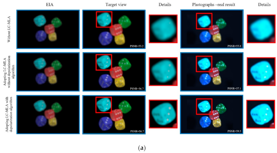
The comparative results of the light field display on the smartphone are shown in
Figure 5. Peak signal to noise ratio (PSNR) is employed to qualify the light field display views. We adopted three control group experiments to compare the effect of using LC-MLA with the depolarization algorithm. These experiments were as follows. The first group adopted the regular glass type MLA without LC-MLA (glass MLA-type 150-5C from Thorlabs Co). The second group adopted LC-MLA without depolarization algorithm (the applied voltage at 2 V
rms) [
33]. The third group adopted LC-MLA with a depolarization algorithm (the lens state is the applied voltage at 2 V
rms, the non-lens state is without applied voltage).
Figure 5a gives the “Dices” with 1920 × 1080 pixels. After adopting LC-MLA with the depolarization algorithm, we can see that the image quality of photographs-real results improved from 55.8 dB to 59.3 dB by 1.06 times. The edge detail of “Dices” becomes clear. The image quality of photographs-real results changed from 57.61 dB to 59.81 dB because the depolarization algorithm is a post-processing method that utilizes several image filters, such as a bilateral filter. Therefore, the image quality has an improvement to a certain extent.
Figure 5b is the “Dragon.” The PSNR of photographs-real results was improved from 55.81 dB to 57.71 dB by 1.03 times. The inner contour of “Dragon” has arisen, while the inner of the primary effect has detailed information. The improvement is that, after adopting the depolarization algorithm, the refractive index experienced by the o-wave remains unchanged with the angle between the incident ray and the director of LC. The LC-MLA did not tune the o-wave. Namely, only the LC-MLA adjusted the e-wave part of the incident ray. The lens state of LC-MLA changed only e-wave but not o-wave. With the use of the proposed depolarization algorithm, the polarization effect of LC-MLA, a challenge for LC devices, was greatly removed compared to the other control group with LC-MLA. Therefore, the high-resolution intermediate 3D image result was received on the display panels of the smartphone in video mode.
Moreover, the performance of the presented result verified the depolarization algorithm to a certain extent, in good agreement with the anticipation. The LC-MLA methods satisfied relatively fast-response without non-mechanical components, the pixel size, and lens pitch without manufacturing limitations to achieve a high spatial resolution of light field display. However, the glass-type solution suffered from mechanical movements and complicated fabrications, easily causing light field display’s low spatial resolution issue. Nevertheless,
Figure 5 verified the advantages of adopting LC-MLA in light field display over the conventional glass type.
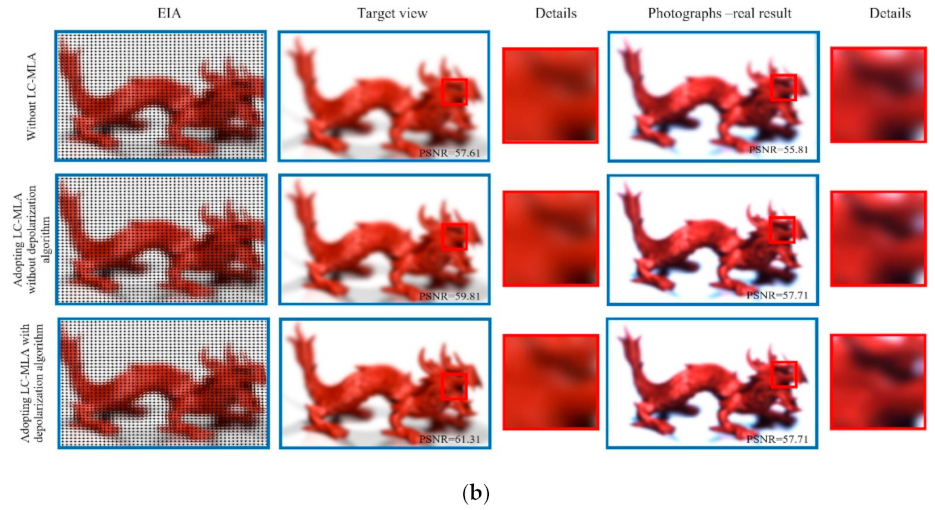
In addition to the LC-MLA above, the PDLC film was applied to modulate the intermediate 3D images to realize a wide FOV. The LC directors in the PDLC system were arranged as micron-sized droplets dispersed in the polymer matrix by the phase separation. In each droplet, the LCs aligned in a specific direction to minimize the free energy of the PDLC system. However, at the off-state of the externally applied voltage, the LC alignment direction varied from a droplet to another droplet, causing light scattering macroscopically. Currently, the transmittance of the PDLC film is low. When the applied voltage was added to the PDLC film, the LC droplets rotated to align along the vertical direction. Under this situation, the PDLC film changed from an opaque state into a transparent state. The high transmittance and the strong scattering features allow PDLC film to realize the improvement of the light field display.
Figure 6 shows the results of adopting the PDLC film. The LC-MLA with depolarization algorithm is ten times electrically tunable from 0 V
rms to 10 V
rms at 1 V
rms/step, and the PDLC film has the time synchronization strategy of applying the externally applied voltage. The results of the light field display based on the visual staying phenomenon depended on the intermediate 3D images and the strategy of changing the applied voltage of the PDLC film. The FOV of the results was relatively wider, about 25° × 25° range over the conventional solutions, including a holographic diffuser with relatively small FOV [
34], which was highly consistent with our prediction.
Nevertheless, the effect of adopting the PDLC film in the proposed light field display is much more evident than that of other solutions without adopting PDLC film. The reason for light field display improvement is that the proposed PDLC film in the desired direction modulates the incident ray and has relatively high scattering efficiency, which is suitable for improving the light field display. The LED and beam splitter was applied to solve the issues of the conventional solutions. Especially, the latter one is a vital means to compensate for the energy attenuation of multiple times propagating through these optical devices in the proposed light field display system.
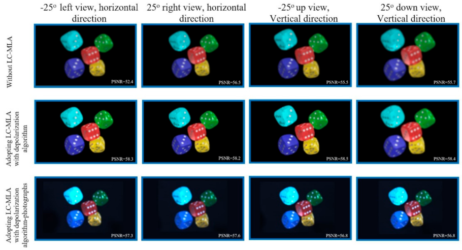
The different views along the horizontal and vertical directions are provided by using CCD to present the performance of the proposed light field display system. The experimental result about −25° left view and horizontal direction indicates that PSNRs of perceived 3D images, −25° left view along a horizontal direction, are noticeably improved from 52.4 dB to 58.3 dB by 1.11 times, as shown in
Figure 7. Details of results obtained by the proposed method are mostly expressed in enlarged areas. Although some artifacts appear on edge in the results, the performance of the proposed method is still much more acceptable, especially compared to the other light field display methods without adopting LC-MLA or PDLC film. The “Dices” views are presented in
Figure 7, which have full-color and full-parallax for light field display. The strategy of adopting PDLC film is beneficial for expanding the FOV, where most of the incident ray with a large viewing angle is present [
35].
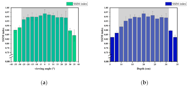
Structural similarity (SSIM) is an index to measure the similarity of two images. In general, this index is used to evaluate image quality. Nowadays, it is also introduced in light field display to assess the image quality of the photograph-real result [
36]. This index is also a complete reference parameter. That means the computation of SSIM needs a reference image. In this study, the reference image for this experiment is chosen as the target view in
Figure 7.
Figure 8a shows the SSIM values at different viewing angles for the “Dices” in
Figure 7. According to the parameters in the proposed system, the computed SSIM values at [−25°,25°] are much higher than other areas, which indicates that the proposed approach has a broader FOV compared to other conventional methods [
35].
On the other hand, the DOF is also another essential index for evaluating the performance of the light field display. There are a lot of research about LC-MLA applied in expanding the DOF field [
37]. The corresponding results are presented in
Figure 8b. Due to the focal length tunable feature, the DOF of the proposed system is enhanced. Based on the geometrical optics and parameters of the proposed method, the theoretical DOF is about 20 cm. The SSIM values are much higher when the 3D object depth is at [10 cm, 30 cm], which illustrates that the proposed system improves the DOF. With further analysis, when the SSIM index is smaller than 0.891, the photograph-real result is out of FOV, as shown in
Figure 8a. Similarly, the photograph-real consequence is out of DOF when the SSIM index is smaller than 0.891, as shown in
Figure 8b. The computational method of the SSIM for FOV and DOF has directly adopted the approach in [
38].
However, there are still some deficiencies in this study. Because this proposed method used several LC devices in the light field display, it still has limitations for some adverse environmental conditions in natural scenes. Moreover, the proposed system is still redundant, considering high image quality. In the later work, we should consider building a much more innovative experimental system with several intelligent optics devices to improve further the image resolution on the premise of ensuring the FOV.


