Abstract
We present a new active optics method for making smooth aspheric, or freeform, mirrors by replication technique from an elastically deformable matrix. The mirror replicas provide an equivalent aberration correction to that of an off-axis segment of a Schmidt plate. The method describes geometry of a chromium stainless steel deformable matrix. Polished flat at rest, the matrix was used as submaster when in a bent state for single replications on a glass substrate. Two plane-aspheric segment mirror replicas are then used as a pair of correctors for a spectrograph telemeter. Located outside the Schmidt plate, in opposite diametric directions, the mirror replicas allow aberration compensation of the singlet convex-plane lens used both as collimator and camera-optics of a spectrograph where the beams are passed twice. The spectrograph design is a “white pupil mounting” for a Cassegrainian telescope. The detector focusing is controlled by fusion imaging from the two mirror replicas. Our results show that the He-Ne beams wave-front error performed by the spectrograph, with each of the two replica mirrors passed twice, compensates at least 93% of the required total aspheric sag. This provides satisfactory results for the telemeter focusing device, which then is quasi-diffraction-limited. A similar replication technique is proposed to obtain a pair of off-axis Schmidt plates for a unit magnification Schmidt-Offner “ideal imager”. Such a system is well suited for Laser Guide Star adaptive optics applications in modern astronomy.
1. Introduction
We hereby describe freeform Schmidt mirrors designed and built by a new active optics method for the telemeter segment-mirrors of the CFHT CassHawEC spectrograph that we had no time to present before because of a lack of time. It was the time when Baranne designed this spectrograph around 1980 for a Lallemand-Duchesne electronic camera (EC), thus, just before CCD camera advent.
The main reason for this paper comes from Rakich [1,2] discovering “ideal imaging” transport systems, called Schmidt-Reed-Offner or briefly Schmidt-Offner relays, where off-axis portions of a Schmidt plate allow correcting at least all third-order aberrations, i.e., Seidel aberrations. These telecentric unit-magnification imagers provide as well finite object conjugates as finite pupil conjugates. Theses absolute instrument properties are achieved by using an additional freeform Schmidt plate. Rakich previously investigated optical design cases of many reflecting anastigmatic optical systems and published a retrospective study of such systems [3].
Compared to the classical case of a Schmidt system using an aspheric corrector as first element, research on the best angular resolution for the case of all-reflective—or including a reflective grating—off-axis Schmidt systems led to the discovery of a new location of the null-power zone for the field aberration optimization. This elliptic zone must be times larger than that of the clear aperture. The results by Lemaitre [4] were applied to the design of wide-field spectrographs and to the design and construction of the giant 4-m reflective Schmidt telescope LAMOST by Wang, Su et al. [5] for fiber-fed spectroscopic surveys in Xinlong Observatory.
Lemaitre showed also in “Astronomical optics and elasticity theory-Active optics methods” [6] that large manifolds of optical shapes can be generated. These methods apply to lenses, mirrors, and diffraction gratings by using either stress polishing at lab, or in situ stressing, or replication techniques with deformable matrices. Active optics methods based on elasticity theory of thin plates were investigated by Lemaitre leading to new solutions for generating toroid surfaces with vase forms [7]. A more recent proposal was investigated for ultraviolet instruments FIREBall and MESSIER [8]. Expected to be launched in 2022, FIREBall is a 1 m telescope with multi-object spectrograph whose goal is to detect Ly-alpha emission lines around galaxies; the disperser is an elliptical symmetry freeform reflective grating obtained from replication of a stressed matrix. In a preliminary stage, a plane grating is deposited on the unstressed matrix. MESSIER proposal is a three-mirror all-reflective Schmidt telescope whose goal is to provide a clean spread-function imaging by avoiding any diffractive element through the beams; its optical design is optimized for curve detectors. The freeform correcting mirror is a hollow double vase-form with elliptical symmetry, which allows aspherization by stress polishing.
The present method was designed, a long time ago, for making smooth freeform optical surfaces either for obtaining reflective or refractive replicas. This is an answer to the question posed by Rakich for the complete design of its “ideal imager” with freeform corrector plates for Laser Guide Star Adaptive Optics (LGSAO) applications in modern astronomical observatories [1,2].
2. Generating a Telemeter Mirror Pair for CFHT CassHawEC Spectrograph
An active optics method was developed years ago (around 1982) for making freeform mirror segments that, due to lack of time, we did not present earlier. This method provided an equivalent aberration correction to that of the spectrograph Schmidt plate but located off-axis the plate clear aperture. The spectrograph design is a Baranne’s white pupil mounting [9] that uses a cross-disperser made of a Carpenter-prism transparent grating and an echelle reflective grating. It receives the optical beam of a Cassegrain telescope focus at f/8 and was installed at CFHT in 1984.
The white pupil mounting was invented by Baranne [10], in French montage à pupille blanche, and provides the optical conjugation imaging of the pupils. The input pupil of the telescope primary mirror is reimaged at the diffractive element, and can be potentially reimaged by a successive image transport system from the previous dispersive element to the next dispersive cross element pupil. In most cases, the accurate pupil conjugation is achieved by a field lens. White pupil mounting spectrographs are widely adopted in astronomy.
This CFHT CassHawEC spectrograph was built in the period 1978–1983 under the responsibility of INSU technical division in Paris. Collimator and camera optics are a single convex-plane lens at f/8 and a 20-cm clear-aperture Schmidt plate, both passed twice through. The two telemeter beams are slightly decentered from the field of view and provide an auto-collimated access to the center of the detector.
Spherical aberration of the single lens spectrograph is corrected by a Schmidt plate that is virtually centered at the center of curvature of the lens spherical convex face. Although the telescope primary mirror pupil is naturally re-imaged near the echelle grating, a low powered lens before the telescope focal plane provides a rigorous pupil location (or stop) at the middle of this grating. The design provides high-resolution spectral imaging over a wide and square field of view.
The two off-axis mirror replicas are located slightly outside the circular Schmidt plate on opposite diametric directions. They directly reflect light at the detector through the spectrograph single lens passed twice—without reaching the Schmidt plate and dispersers. The mirror replicas and spectrograph singlet lens act as a telemeter that allows checking the focusing set-up of the detector by fusion of two telemetric images (Figure 1).
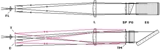
Figure 1.
Optical path scheme of the 20-cm pupil aperture CFHT-CassHawEc spectrograph including a field-lens (FL). The telemeter (T) uses two replica telemeter mirrors (TM) for the focusing set-up of a 2D detector (D). Each replica mirror TM compensates aberration of the convex-plane lens (L). Their shape provide an equivalent correction to that of the extended-size Schmidt plate (SP). Pair of pencil rays for telemeter in red color.
Lemaitre showed that active optics methods and elasticity theory [3,4,5] allow generating many freeform shapes for astronomical instrumentation. The present method was developed for making off-axis aberration corrective mirrors equivalent to that of a zonal Schmidt plate. It describes geometry of a quenched chromium stainless steel deformable matrix. The optical clear aperture is a sectorial contour. Elasticity theory led us to a prismatic radial thickness distribution that decreases when the off-axis direction increases.
Polished flat at rest, the matrix was used as submaster when bent for mirror replications via an epoxide resin on a glass substrate. We thus obtained plane-aspheric freeform replica mirrors that were used as a pair of correctors for a spectrograph telemeter. These corrector mirrors were mounted in opposite directions and slightly outside the Schmidt plate, thus allowing set-up focusing of the detector.
Those plane-aspheric replica mirrors compensate for third-order spherical aberration, Sph-3, which in a first approximation is locally equivalent to third-order astigmatism, Astm-3, but more accurately includes the coma mode, Coma-3.
3. Deformable Matrix Geometry and Elasticity Design
A quenched chromium stainless steel deformable matrix in Fe87Cr13 alloy from Ugima-4028 X30C13, Ugine, France (about similar to AISI-420 alloy), is selected. This alloy provides (i) a high deformability, (ii) an excellent linear stress–strain relationship and, (iii) an excellent ability for polishing.
Active area geometry of the deformable matrix is able to generate replicas that compensate for zonal spherical aberration Sphe-3 outside the 200-mm clear aperture diameter of a Schott UBK7 refractive Schmidt plate. The rectangular size of mirror replicas (TM in Figure 1) are 20 × 30 mm2 in radial and tangential directions respectively.
The asphericity amount of the off-axis replicas is determined from the Schmidt plate—and its central wavelength refractive index—as an equivalent correction transferred to the replica mirror shape. Of course, due to the replication process, the matrix and replica have opposite shapes.
The elasticity design of the deformable matrix (Figure 2) is made of three zones A, B, and C, in a single holosterique piece of a 24° angular sector, θ = ± 12°, that defines a bridge as follows. A—an inner rigid unmovable zone. B—a deformable area of thickness t(r) from r1 = 105 mm to r2 = 125 mm in radial directions, and that should be close to a rotational symmetry in the tangential direction. C—an outer rigid part able to rotate around a tangential axis and translate in the axial direction (Figure 2c).
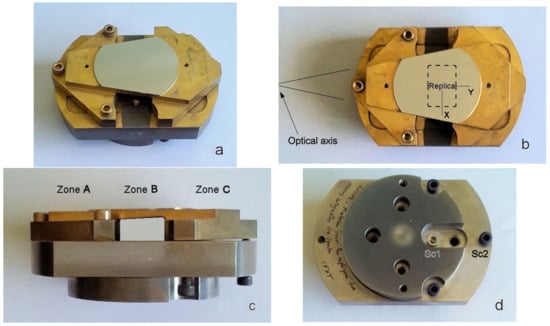
Figure 2.
Various views of the deformable matrix on its bending support after removing of replica plates: oblique, front, lateral and rear views of the matrix-support system, (a), (b), (c), and (d) respectively. In (b), dotted lines show the 20 × 30 mm2 replica clear aperture area which is centered at 115 mm off-axis.
Round corners of radius 1 mm are designed at the junctions of zones A-B and B-C, thus avoiding stress concentrations.
Boundary conditions of the deformable zone B are:
- Built-in link at the curved outer zone A and also for curved inner zone C,
- Free-edge along the straight lines of the sector bridge.
The integration of elasticity equation, for determining the thickness t(r) of deformable zone B in radial direction, is derived from the wavefront curvature variation of the Schmidt plate correction. Zone B remains of constant thickness along the two concentric circles, and centered at the summit of angle 24° of the sector bridge, i.e., the center of the original full aperture Schmidt plate.
The Schmidt plate shape is classically represented by z = (N − 1)(A2SP r2 + A4SP r4). In the third-order optics theory the radial curvature variation of a Schmidt plate that compensates spherical aberration can be defined only by a fourth power radial term. Similarly for zone B (Figure 2c), in cylindrical coordinates, the shape of the matrix to generate by flexure is of the form
where the first term represents the third-order term of the Schmidt Plate figure, and the last term is relative to the matrix figure to generate. The r1, r2, radial limits define the annular area where the two telemeter mirrors are replicated from the active matrix.
Because the telemeter replica mirror-pair is just located outside the Schmidt plate, the optical design at f/8 is expanded at f/6.2 by just increasing the beam clear-aperture. One selects hereafter the He-Ne wavelength, λ = 632.8-nm, for optical testing. Considering only the 4th-power term of the even aspheric refractive UBK7 Schmidt plate, one has A4-SP = −5.012 × 10⁻¹⁰ mm−3. An identical wavefront correction can be obtained for a reflective element. The mean refractive index is N = 1.515. Then the matrix correction, used as a mirror, is 1/(N − 1) times smaller in deformation amplitude than the Schmidt plate passed twice through. Taking into account the fact that a segment mirror—replicated from the matrix—leads to an opposite shape, one selects coefficient A4 as
for the matrix when bent and r0 for the segment mean off-axis distance respectively.
The matrix curvature function C(r), or second order derivative, is expressed in radial direction by
where the curvatures are all concave.
The thin plate theory of small deformations defines classically the rigidity D(r) of a plate as [3,6]
where E = 205 GPa is the Young modulus and = 0.315 the Poisson’s ratio of the matrix in Fe87Cr13 alloy, and t(r) the thickness. Assuming in a first approximation that the matrix is bent into a rectangular surface (cf. T & WK [11], p. 5), the flexural moment in radial direction is express as:
where the right term includes the substitution of Equations (3) and (4).
The equilibrium of the bridge (zone B) is achieved when the bending moment at the boundaries are equalized without applying any external load on the plate. Then M(r1) = M(r2) entails, since radial moments are constant along the bridge,
which allows determination of t2 either from t1 or t0, and where the thickness t0 holds for the radius r0.
A convenient calculation of the maximal radial stress σr-Max leads us to (cf. T & WK [11], p. 5)
Setting t0 = 4.70 mm for r0 = 115 m, the bridge thickness t(r) decreases in radial direction since one obtains
t1 ≡ t(r1 = 105 m) = 5.00 mm, t2 ≡ t(r2 = 125 m) = 4.45 mm.
This result leads us to a secure maximum stress, σr ≅ ±27 MPa, which is much lower than the stress at 0.2% elongation of σ0.2 = 650 MPa as given by UGIMA Corp. for the 4028 material [12].
Although an off-axis zonal Sph-3 correction may be mainly assimilated as an astigmatism correction Astm-3, one prefers—instead of a constant thickness plate—taking into account the radial thickness variation as derived from the above law, t3r2 = constant (cf. Equation (6)), which provides also coma correction Coma-3.
For practical reason due to machining of the bridge, the thickness of zone B is made as varying linearly in radial direction, i.e., a conical shape where the thickness is constant in the tangential direction.
4. Deformable Matrix-Modeling and Optical Testing
4.1. Matrix Aspheric Shape and Modeling
A preliminary modeling with Zemax code allows determining the optical patterns obtained at a surface area (ΔY = 20 × ΔX = 30)-mm2 in size and off-centered of Y = 115-mm (see Figure 2b). Then the spectrograph design at f/8 is extended to f/6.2 for getting room to the telemeter mirrors that are diametrically opposite at the level of the Schmidt plate. The aspheric A4 coefficient is given by Equation (2). Image through focus shows the astigmatic pencil sections—before and after Sph3 aberration correction—with the spectrograph lens passed twice (Figure 3a,b). Image at focus shows the quasi-astigmatism wavefront aberration, mainly Astm3, before correction of the telemeter mirror (Figure 3c).
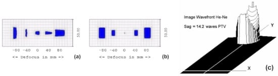
Figure 3.
Images through focus before and after Sph-3 correction of the spectrograph telemeter 20 × 30-mm2 area (a) before and (b) after correction. Wavefront shape from telemeter flat-segment at focus image shows Astm3 aberration before apherization over a 30-mm diameter area—wavefront tilt removed (c).
4.2. Modeling Optical Test with an Off-Axis Reflecting Image Transport
Setting now the origin of an x, y, z coordinate system at the center of the matrix replica area, the aspheric sags are
where hx and hy are semi-aperture sizes.
zx = Cx hx2/2, zy = Cy hy2/2 with hx = ΔX/2, hy = ΔY/2,
From the value of the matrix coefficient A4 in Equation (2) and the curvature expressed by Equation (3), the radial curvature is C0 = 12A4 r02, where r0 = 115 mm at center of the segment. Assimilating the matrix shape locally as a cylindrical shape, Cx = 0 and Cy = C0, leads us to the sags
zx = 0 and zy = 6 A4 r02 hy2.
For a circular matrix area of ΔY = ΔX = 30 mm diameter the cylindrical sag in the y-direction is zy = 4.61-µm PTV, which corresponds to 7.28 He-Ne fringes, i.e., an optical path difference of 14.56 He-Ne fringes with respect to flat reference.
We consider hereafter two options for optical testing of the matrix.
- OPTION 1–A null-test mounting: A finite distance optical design where a punctual off-axis source object illuminates a doublet lens and a flat mirror used over a 30-mm circular aperture area. The beams are passed twice through the achromatic lens of focal length F = 500 mm which are free from Sph3 aberration (Figure 4a). The beam image shows astigmatism mode Astm3. Zemax optimization allows determining the principal beam off-axis deviation angle between the source object and its image that provides the same amount of toric sag (Figure 4b) than that of the previous cylindrical sag of the matrix when actively deformed. The deviation angle 2θ = 15° corresponds to an object and image heights of 66 mm. The astigmatism length between sagittal and tangential foci is L = 20 mm.
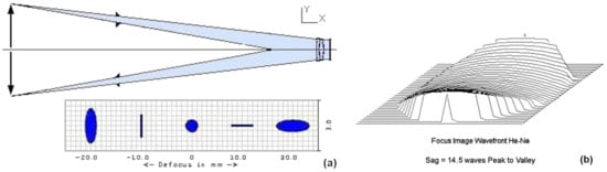 Figure 4. Finite distance mounting with a flat mirror 30-mm circular clear aperture and an achromatic lens passed twice through. This mounting (a) provides an equivalent astigmatism sag amount (b) than that of the matrix.
This null-test mounting is performed by replacing the flat mirror by the bent matrix.
- OPTION 2–Twyman-Green Interferometric mounting: The reflected wave of the plane-aspheric deformed matrix is compared to the reflected wave of a plane reference mirror in a two-arm interferometer. The result obtained from this option is presented hereafter.
4.3. Matrix Active Optics Set-up and Interferometric Result
After realization and flat polishing of the matrix when unstressed, the flexural elastic bending is achieved by screw actuators that generate a tangential rotation and an axial translation of zone C. The centering of replicas is at 115 mm off-axis radial distance. A gold coating allowed separation of mirror replicas.
Controlled rotation and translation of zone C about a rigid stand (84 × 120 mm) generate a concave aspheric shape in radial direction. The aspheric amount of local Sph3 aberration of the matrix is set for a mirror correction as equivalent to the wavefront correction generated by the refractive Schmidt plate.
Two actuator screws, at zone C, generate set-up of the deformable aspheric surface. These are a pulling screw Sc1 and a pushing screw Sc2 near the edge (Figure 2d). The rectangular mirror replicas were 20 × 30-mm aperture, 6-mm thickness, on glass substrates by using epoxide polymer resin.
Optical testing of the matrix deformation is considered over a 20 × 30-mm area. The image of this area is obtained via a CCD camera and a positive objective lens of the Twyman-Green interferometer. The monochromatic light source with an interferential filter at λ = 650 nm, 4-nm band-pass, allows providing interferogram data reduction with Quick Fringes code (Figure 5).
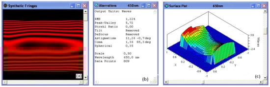
Figure 5.
Synthetic fringes of the deformed matrix under test (a), aberration table analysis (b), and surface plot (c). The freeform matrix optical test is reduced with Quick Fringes at λ = 650 nm with 5.72-fringe astigmatism PTV, i.e., 5.8 He-Ne fringes over 20 × 30mm area.
4.4. Interpretation and Discussion of the Results
The set-up of the screw actuators, Sc1 and Sc2 (Figure 2d), is adjusted up to obtain satisfactory results from the theoretical request. From Table in Figure 5b, the Peak-to-Valley toroidal shape corresponds to 5.8 He-Ne fringes (633 nm) for 20 mm aperture in radial direction. Comparing astigmatism—showing a slightly toric shape in Figure 5a and a saddle-like shape in Figure 5c—provides results in close agreement together. For a 30-mm aperture in radial direction this would leads us to (30/20)2 times = 13.1 He-Ne fringes PTV compared to 14.2 and 14.5 fringes as displayed in Section 4.1 and 4.2 respectively.
The error is small, of the order one fringe i.e., 7% deviation. The coma term of 1.3 fringe in Table Figure 5b is mainly due to our matrix prismatic thickness design that should provide a complement aberration correction. From the table of Figure 5b, it can be seen that the zonal spherical aberration is negligible. One may notice from Figure 5a that the anticlastic effect of the flexure is found negligible over the tangential direction since it is smaller than a quarter of He-Ne fringe.
5. Conclusions
Present results from the matrix toroidal shape show that, for beams passed twice at the spectrograph, the wave-front error is close to one He-Ne wavelength. This provides satisfactory results for the telemeter-focusing device, which then is quasi-diffraction-limited.
The bridge of the matrix used for replications is with a conical thickness. Instead of a constant thickness, this allows including higher order corrections of the zonal Schmidt plate. This provides best modeling by generating zonal aberration corrections equivalent to astigmatism and coma corrections.
Active optics replication techniques from a deformable matrix can be applied to the construction of one or two zonal Schmidt plate segments for a pupil relay Schmidt-Offner imager. This unit magnification ideal imager relay was proposed by Rakich [1,2] for LGSAO and also proposed by Ciliegi et al. [13] for laser tomography adaptive optics (LTAO). For various distances of earth’s atmospheric layers, the volume spaces of projected pupils are exempt from all five Seidel aberrations and from pupil aberrations.
Such zonal Schmidt plates, as replicated from an active matrix, may potentially provide an ideal imager relay solution. Extremely smooth surfaces contribute widely to perform high-angular resolution.
Author Contributions
Conceptualization, G.R.L.; methodology, G.R.L.; software, P.L.; validation, P.L. and G.R.L.; investigation, G.R.L.; resources, P.L. and G.R.L.; data curation, P.L. and G.R.L.; writing—original draft preparation, G.R.L.; writing—review and editing, G.R.L.; visualization, P.L. and G.R.L.; supervision, G.R.L.; project administration, G.R.L.; funding acquisition, We had all the material. All authors have read and agreed to the published version of the manuscript.
Funding
This research received no external funding.
Institutional Review Board Statement
Not applicable.
Informed Consent Statement
Not applicable.
Data Availability Statement
Data supporting reported results remain at LAM. Are not available outside LAM.
Acknowledgments
This paper is dedicated to the memory of the brilliant French astronomer in optical design research and development, André Baranne, who passed away on 26 January 2021, in his 89th year. He invented the “white pupil mounting”—as briefly described in this paper—for spectrographs mainly using cross-dispersers. Baranne was the father of ELODIE, which permitted discovering the first exoplanet around star 51-Pegasus in 1995. His famous mounting has since been widely adopted by the international community. More information can be found on the LAM website.
Conflicts of Interest
The authors declare no conflict of interest.
Nomenclature
| AO | Active Optics and/or Adaptive Optics |
| CassHawEC | Cassegrain Spectrograph of Hawaii Electronic Camera-CFHT |
| CCD | Charge Coupled Device |
| CFHT | Canada France Hawaii Telescope |
| EC | Electronic Camera |
| FireBall | Faint Intergalactic Redshifted objects for Balloon observations |
| LAMOST | Large Sky Area Multi-Object Fiber Spectroscopic Telescope |
| LGSAO | Laser Guide Star Adaptive Optics |
| LTAO | Laser Tomography Adaptive Optics |
| MESSIER | Telescope project dedicated in memory to astronomer Charles MESSIER |
| PtV or PTV | Peak to Valley |
| UBK7 | Borosilicate-Crown in grade U, index ref. [7], by Schott Corp. |
References
- Rakich, A.; Rogers, J.R. A Maxwellian “ideal imager” optical relay suitable for AO applications. In Proceedings Volume 11451, Advances in Optical and Mechanical Technologies for Telescopes and Instrumentation IV; SPIE: Bellingham, WA, USA, 2020; p. 11451. [Google Scholar] [CrossRef]
- Rakich, A. Optical Systems Capable of Forming Highly Corrected Images of 3-Dimensional Objects. International Patent PCT/NZ2020/050105, 25 March 2021. [Google Scholar]
- Rakich, A. Reflecting anastigmatic optical systems: A retrospective. Opt. Eng. 2018, 57, 101701. [Google Scholar] [CrossRef]
- Lemaitre, G.R. Sur la résolution des télescopes de Schmidt de type catoptrique. Comptes Rendus L’acad. Sci. 1979, 288, 297–299. Available online: https://www.gerardlemaitre.com/wp-content/uploads/2015/06/Angular-resolution-of-all-reflective-Schmidt-telescopes.pdf (accessed on 14 February 2022).
- Wang, S.-G.; Su, D.-Q.; Chu, Y.-Q.; Cui, X.; Wang, Y.-N. Special configuration of a very large Schmidt telescope for extensive astronomical spectroscopic observations—LAMOST. Appl. Opt. 1996, 35, 5155–5161. [Google Scholar] [CrossRef] [PubMed]
- Lemaitre, G.R. Astronomical Optics and Elasticity Theory—Active Optics Methods; Springer: Berlin/Heidelberg, Germany, 2009; ISBN 978-3-540-68905-8. [Google Scholar]
- Lemaitre, G.R. Elasticity theory of thin plates and active optics. Solutions for generating toroid surfaces with vase forms. Appl. Math. Math. Phys. 2015, 1, 77–100. [Google Scholar] [CrossRef] [Green Version]
- Lemaitre, G.R. Active optics in astronomy—Modeling of deformable substrates: Freeform surfaces for FIREBall and MESSIER. J. Mech. Behav. Mater. 2018, 27. [Google Scholar] [CrossRef]
- Baranne, A. Un nouveau montage spectrographique. Comptes Rendus L’acad. Sci. 1965, 260, 2383. [Google Scholar]
- Baranne, A. White pupil story or evolution of a spectrographic mounting. In Very Large Telescopes and Their Instrumentation, ESO Conference and Workshop Proceedings, Proceedings of the ESO Conference on Very Large Telescopes and Their Instrumentation, Garching, Germany, 21–24 March 1988; Ulrich, M., Ed.; European Southern Observatory (ESO): Garching, Germany, 1988; p. 1195. [Google Scholar]
- Timoshenko, S.P.; Woinowsky-Krieger, S. Theory of Plates and Shells; McGraw-Hill International: New York, NY, USA, 1959; p. 5. ISBN 0070858209. [Google Scholar]
- Ugitech Corp. UGIMA 4028W. 1990. Available online: https://eservices.ugitech.com/CatalogDocuments/BarProducts.pdf (accessed on 14 February 2022).
- Ciliegi, P.; Agapito, G.; Aliverti, M.; Arcidiacono, C.; Balestra, A.; Baruffolo, A.; Bergomi, M.; Bianco, A.; Bonaglia, M.; Busoni, L.; et al. MAORY: The adaptive optics module for the Extremely Large Telescope (ELT). In Proceedings Volume 11448, Adaptive Optics Systems VII; SPIE: Bellingham, WA, USA, 2020. [Google Scholar] [CrossRef]
Publisher’s Note: MDPI stays neutral with regard to jurisdictional claims in published maps and institutional affiliations. |
© 2022 by the authors. Licensee MDPI, Basel, Switzerland. This article is an open access article distributed under the terms and conditions of the Creative Commons Attribution (CC BY) license (https://creativecommons.org/licenses/by/4.0/).